a hybrid contact state analysis methodology for robotic
TRANSCRIPT
1
A Hybrid Contact State Analysis Methodology for Robotic-Based Adjustment of Cylindrical Pair
B. Shirinzadeh1, Y. Zhong2, P. D. W. Tilakaratna1, Y. Tian3, M. M. Dalvand1
1Robotics and Mechatronics Research Laboratory, Department of Mechanical and Aerospace Engineering, Monash University, Clayton, VIC 3800, Australia 2Department of Mechanical Engineering, Curtin University of Technology, Perth, WA 6845, Australia 3School of Mechanical Engineering, Tianjin University, Tianjin 300072, China
Abstract
The peg-in-hole insertion and adjustment operation is one of the most common tasks in the robotic and automatic assembly processes. Fine motion strategies associated with adjustment operations on a peg-in-hole are fundamental manipulations that can be utilised in dynamic assembly and reconfigurable workholding or fixturing systems. This paper presents a comprehensive study of robotic-based height adjustment of a cylindrical pair based on maintaining minimum contact forces between the links. The outer link is held by the end-effector of a 6-DOF (Degrees of freedom) serial articulated robot manipulator. The environment represented by the inner-link can be either static or dynamic. A force based approach and a dvalue approach are established to determine the type of contact that exists between the links of a cylindrical pair, and to extract control parameters. Based on the comparison and analysis of these two approaches, a hybrid methodology is established by combining a dvalue approach with a force based approach for contact state determination. Formulations capable of extracting necessary control parameters which ensure minimum contact forces between the links are established from both planar and spatial viewpoints under both static and dynamic environmental conditions. Experimental results demonstrate the effectiveness of the proposed methodology. Keywords: Lower pairs, dynamic adjustment, contact state determination, and robotic manipulations.
1. Introduction Lower pairs are the fundamental building blocks of many mechanisms and form the basis for all assembly operations. As an example, tightening a nut and a bolt is represented by a screw pair, where inserting a microchip into its slot can be regarded as the height adjustment of a prismatic pair [1]. General manufacturing/assembly tasks such as position adjustment of a sleeve in a shaft prior to welding are described by a cylindrical pair. Likewise, the adjustment of a hinge is described by a revolute pair. The research on lower pairs has received considerable attention [2-8]. Automated planning of robotic manipulation for sliding workpieces (i.e. planar pairs) on a surface has also been extensively studied [3, 5, 8, 9]. In qualitatively demonstrating the alignment of a workpiece under an open-loop control, a methodology was developed to determine the locus of centres of rotation for all pressure distributions at the contact surface [8]. Further, the notion of configuration maps was proposed and established to evaluate the sequence of operations required to align a sliding workpiece [9]. Pushing manipulations were investigated on a hinge with negligible effect due to inertia, and a numerical procedure to determine its instantaneous center of rotation was established [3]. Determining the orientation of a polygonal planar object using data from a force/torque sensor attached to a fence,

2
and subsequently using this information on sensory-based manipulations to reorient the object to a desired orientation, offers improvements to sensorless orientation techniques [10-12]. Filtering techniques such as Kalman filter [13] and Bayesian filter [14, 15] were also reported for estimation of contact state and geometric parameters for robotic cube-in-corner assembly. However, the Kalman filter method requires prior knowledge on contact formulation, and the Bayesian filtering method is sensitive to prior probability distribution of the contact state. Manipulations on threaded fastenings, which are effectively manipulations of screw pairs, account for over 25% of assembly operations [2, 16]. An analytical model was developed for mapping the required torque signals for a self-tapping screw insertion [16]. Screw jamming, cross threading and thread stripping are some of the problems encountered during a self-tapping screw insertion [17]. Senevirate et al established a Weightless Neural Network (WNN) based strategy for monitoring self-tapping screw insertions [17]. Effectiveness of the strategy was proven based on the applied torque and the insertion angle estimated via the WNN. Another important area is the automated and reconfigurable fixturing or workholding [18-21]. Reconfigurable workholding methodologies and systems utilise mechanisms and modules that can be reconfigured or rearranged to layouts which would locate and constrain different workpieces within a family [22-28]. When such fixture modules are reconfigured by a manipulator, the basic structure of the mechanism would generally be a cylindrical sliding pairs [6, 22, 29, 30]. The sliding pair is adjusted in height and orientation according to geometric characteristic of the workpiece to locate and constrain the workpiece. A theoretical study on robotic-based height adjustment of a cylindrical lower pair was conducted [6]. Although this study mainly focused on a cylindrical pair, a cylindrical pair with a constraint restricting rotation in the axial direction was also analysed. The constrained pair is referred to as a compliant pair and is essentially a prismatic pair. A formulation related to contact forces and robot actuation forces was established. Conditions for jamming and wedging were also developed, and an impedance control scheme was proposed for the purpose of force control. A method was also proposed for the height adjustment of a cylindrical pair based on the type of contact that exists between the two links. The established formulation is for a planar case under static environment conditions. A drawback of this technique is the inability to identify the sense of the misalignment between the pair of links. A further study presented a force based approach to identify the type of contact between a pair of links by employing a fundamental momentum balance [31]. This study was also limited to a planar case under static environmental conditions. Although the latter methodology is capable of identifying the type of contact between the links and extracting necessary control parameters, identification is highly sensitive to friction parameter variations. This paper presents a comprehensive study for automated height adjustment of a cylindrical lower pair. Both a dvalue approach and a force based approach are established to determine the type of contact within a cylindrical pair and extract control parameters. Based on the comprehensive comparison and analysis of these two methods, a hybrid methodology is further established for robotic-based height adjustment of a cylindrical lower pair. The proposed methodology combines the above approaches to effectively identify the contact state from both planar and spatial points of view under both static and dynamic environmental conditions for minimisation of contact forces between a cylindrical pair. The dvalue approach is utilised to determine the type of contact between a cylindrical pair subjected to a robotic-based height adjustment operation. If the type of contact is two-point, the force based approach is subsequently employed to extract necessary parameters for robot control. The main difference between the proposed methodology and other investigations for robotic-based height adjustment of a cylindrical pair is that the underlying contact type between the links is utilised to provide conditions for minimisation of contact forces between the links. As shown in Fig.
3
1, the platform holding the inner link can be static or dynamic, where the latter implies spatial motion. The outer link attached to an articulated robot manipulator is force controlled in the constrained directions X and Y, and position controlled in the direction of the height adjustment, i.e. Z-direction. The F/T (Force/Torque) sensor data is utilised to identify the underlying contact state between a cylindrical pair subjected to a height adjustment manipulation. Necessary conditions for the height adjustment of a cylindrical pair can be maintained only by identifying the type of contact and utilizing this knowledge to maintain minimum contact forces between the links. Experimental results demonstrate the effectiveness of the proposed methodology.
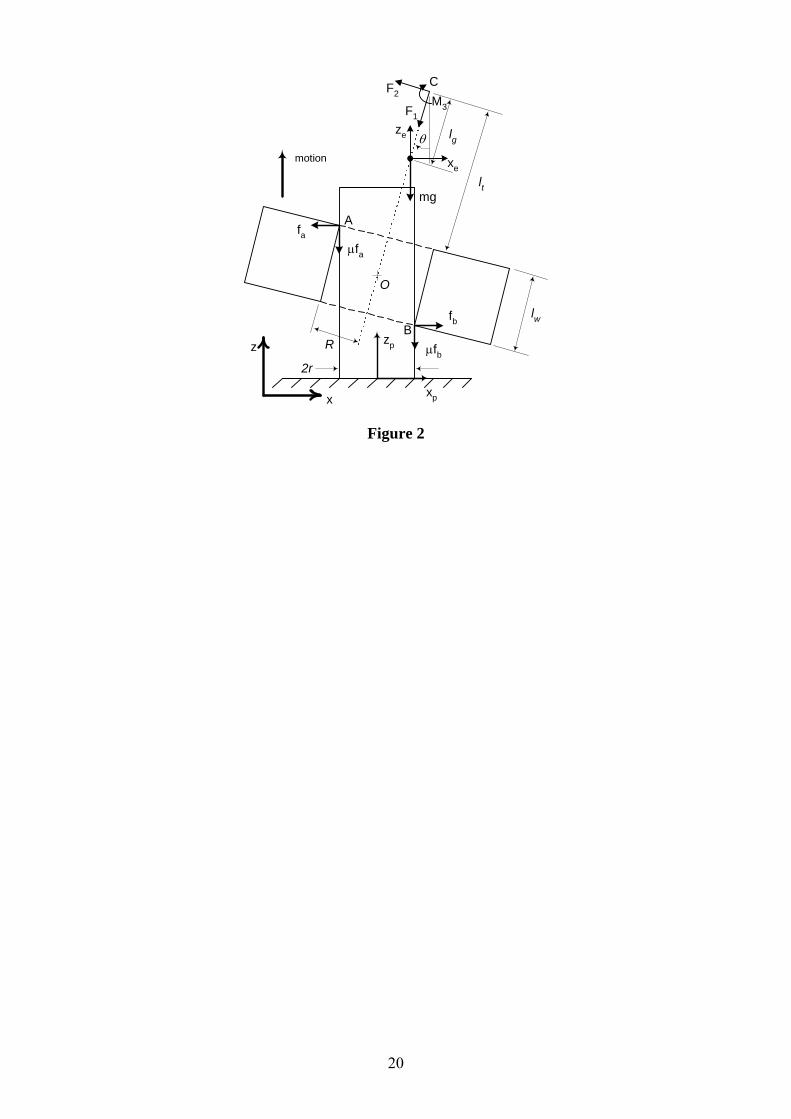
2. Planar Analysis in a Static Environment – Force Based Approach Establishment of a formulation which can be utilised to determine the state of contact between the links of a cylindrical pair subjected to a height adjustment operation is invaluable for robotic control producing minimum contact forces. Planar analysis, which is commonly used for contact state analysis, provides an insight into underlying contact dynamics and a means for assessing robustness of the technique. In this section, planar analysis for a cylindrical pair height adjustment operation under static environment conditions is established utilising a fundamental momentum balance. The analysis emphasises the necessity for determination of the contact state between the links rather than establishing formulations for identification of the conditions that ensure successful height adjustments of a cylindrical pair. 2.1 Force/Moment Analysis The inner link of the cylindrical lower pair is mounted to a static environment, while the outer link is attached to an articulated manipulator wrist. It should be noted that static does not imply rigid, where the stiffness of the environment is theoretically infinite. The free body diagram for planar cylindrical pair height adjustment under static conditions is depicted in Fig. 2. The friction coefficient µ is assumed to be identical at all contact points. No stiction effects are considered. Consequently, a distinction between dynamic and static friction is unnecessary. For the convenience of analysis, the height adjustment is assumed to be along the positive Z-direction. The clearance between the links is also exaggerated for the purpose of visualisation, and does not represent the true scale of parts. Dynamics due to the rotation of the outer link about its longitudinal center axis are assumed to be negligible, and the outer link is considered to be exactly symmetrical about the longitudinal axis. The Z-axis is always assumed to be vertical, and thus eliminating the action of a moment due to the mass m under the assumption of the inconsequential misalignment angle θ. The contact plane coincides with the Xp-Zp plane exactly. F1 and F2 are the force components and M3 is the moment component. These are measured by the wrist mounted F/T sensor. By employing a fundamental momentum balance, the contact forces fa and fb may be written as
ea ZmmgFFFFf
sincoscossin2
11122 (1)
and
eb ZmmgFFFFf
sincoscossin2
12211 (2)
where µ, m, g, θ and eZ are the friction coefficient, mass of the end-effector, acceleration due to
gravity, misalignment angle and linear acceleration along the Z-direction, respectively. If θ has a value of near zero, then sinθ ≈ 0 and cosθ ≈ 1. By using these conditions, Eqs. (1) and (2) become

4
..
212
1ea zmmgFFf
(3)
and
..
212
1eb zmmgFFf
(4)
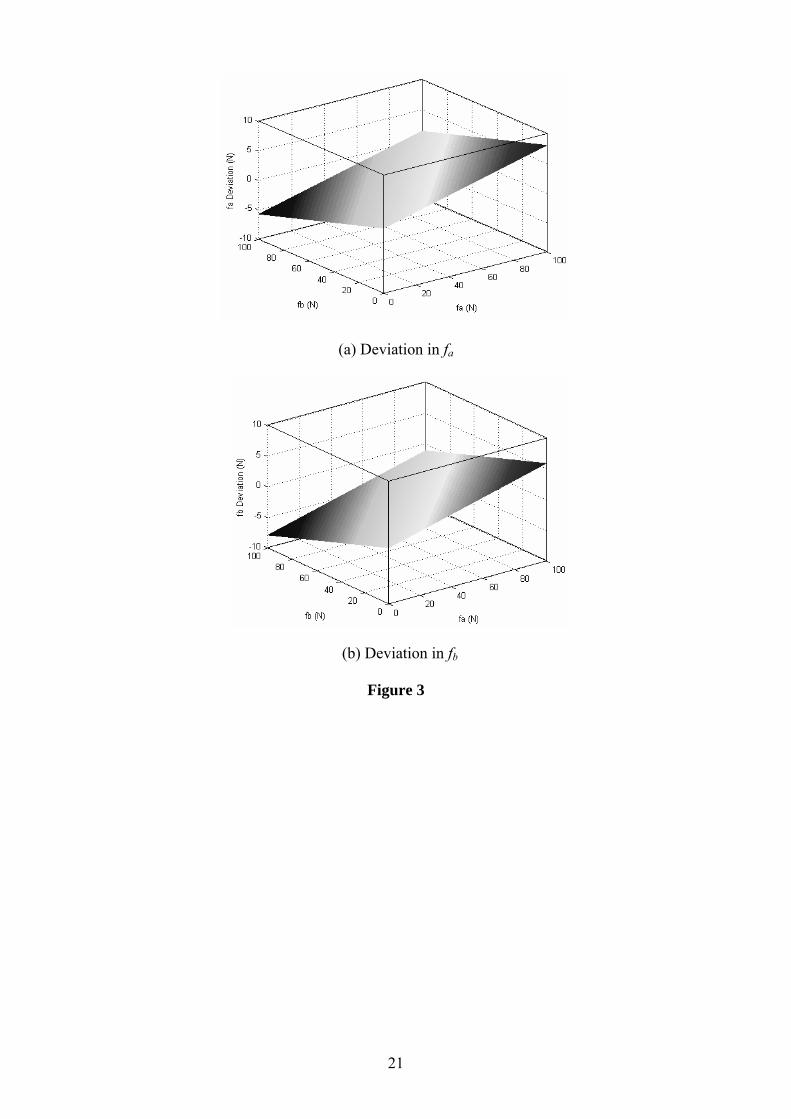
The outer link used in the experiments has a length of 50 mm and an inner diameter of 30 mm. The inner link is 29 mm in diameter. Subsequently, the maximum theoretical angular misalignment between the links is evaluated to be approximately 1.15o. Under the assumption of θ ≈ 0o, the above parameters cause the deviations in fa and fb. Fig. 3 shows the deviations in fa and fb, in which the end-effector mass is 9.513 kg, the friction coefficient is 0.145, and the misalignment angle is 1.15o. From Fig. 3, it can be seen that the maximum possible deviation is in the range of ±8 N. This demonstrates that the assumption of near zero θ is appropriate for achieving a satisfactory result. 2.2 Contact State Identification During a height adjustment process, the possible contact types between the inner and outer links include null contact, single-point contact, line contact, and two-point contact. Among these four contact states, the ideal contact scenario would be the null contact state, although highly unfeasible in reality for parts with tight tolerances. In order to avoid damage caused by excessive contact forces exerted or undesirable surface defects, it is vital to recognise the type of contact between the links. A two-point contact situation can cause excessive forces/moments between the links especially under a dynamic environment. On the other hand, a single point contact can be further manipulated to obtain a near zero contact force between the links by a simple translation, thus aiding and facilitating an improved height adjustment process. Null Contact This is the most favourable condition for the height adjustment operation. In such circumstances, it is absolutely unnecessary for the controller to take any action except for the height adjustment. For minute values of θ, null-contact is simply identified by the conditions F1 ≈ 0 and M3 ≈ 0 or fa ≈ 0 and fb ≈ 0. Single-Point Contact In the case of single-point contact, either point A or point B of the outer link is in contact with the inner link, and the controller action consists of a translational adjustment along the compliant direction so as to minimise the contact force between the links. In addition, either fa ≈ 0 or fb ≈ 0. The values of fa and fb can be evaluated from Eqs. (3) and (4). The extent of the translational controller action is based on the values of fa and fb. Two-Point Contact The contact state between the links or the relevant control action required to minimise contact forces cannot be fully realised with force data only, which is acquired by the wrist mounted F/T sensor. Since the clearance between the links is small, the resultant misalignment θ is minute. Such misalignment between the links is impossible to measure predominantly due to the non-collocated nature of the position feedback sensors, compliance, and drive train backlash of the articulated manipulator. Two-point contact is the case when both fa and fb are non-zero. In such a situation, the information concerning the sense of misalignment θ is essential for robotic control. In order to identify the sense of the misalignment, estimated forces are utilised to evaluate the moments for

5
both positive and negative misalignments, and the determined moments are subsequently compared with the measured moments. Contact points A and B are on the negative and positive segments of Xp, respectively, at all times. This implies that the distance between the contact points and point O in Fig. 2 is likely to be lt or lt+lw, depending on the sense of θ. According to the near zero values of θ are positive or negative, the moments can be determined by Eq. (5) or (6). These moments are referred to as the calculated moments for the convenience of description.
)()()(3 bawtbtac ffRllflfM (5)
)()()(3 batbwtac ffRlfllfM (6)
Given the fact that the measured moment M3 is equivalent to the calculated moment )(3 cM only
if )(3 cM is calculated with the appropriate sense of θ, the comparison of )(3 cM and )(3 cM
to the measured moment M3 provides the correct sense of angular misalignment θ, since the calculated moment cM 3 depends on the location of contact points A and B. Subsequently, the
determined sense and contact forces fa and fb can be utilised by the force and position controllers of the system to minimise the forces between the links. The use of moment M3 for identification of the sense of the misalignment is unique. Essentially, the process involves the determination of fa and fb, which produces the same )(3 cM and )(3 cM
failing the orientation identification process. The relevant condition is described as
)()( 33 cc MM (7) Substituting Eqs. (5) and (6) into Eq. (7), the contact force relationship can be established
ba ff (8) From Fig. 2, it is evident that the above condition would never be satisfied unless sticking is present between the two links, i.e. the links are adhered at the contact point. Therefore, the proposed technique to determine the sense of the misalignment is valid for all values of contact forces. When the links are in a two-point contact situation, the controller action comprises a translational and a rotational correction, which depend on the contact forces and resultant moments. Line Contact Line contact can be considered as a variation of single point contact, where the contact force is arbitrarily distributed along the line of contact between the links. The force distribution depends on the misalignment sense prior to contact, surface texture and system compliance. Nonetheless, both the resultant contact force in the X-direction and the friction force in the Z-direction are as same as those in the case of single point contact. Similar to the case of single point contact, the overall friction force μfa is acting along the compliant direction, i.e. the negative Z direction. It should also be noted that the resultant force fa is the same as the contact force obtained in the case of single-point contact. In order to distinguish between line contact and single point contact, it is necessary to identify the region where the resultant force is acting along the F1 direction. The dvalue concept described in the

6
next section is utilised to distinguish between the line contact and the single-point contact. Although the line contact and the single-point contact can be distinguishable, it is totally unnecessary to perform such verification for robotic control since contact forces under both of these conditions would be identical and the adjustment planner and controller would perform a translational correction in order to facilitate the adjustment.
3. Planar Analysis in a Static Environment - dvalue Approach The methodology established in the previous section for determination of the contact state between a cylindrical pair needs to estimate contact force values fa and fb. To avoid the estimation of contact forces fa and fb, a dvalue approach is established to distinguish between different contact states according to the value of d, which is referred to as the “dvalue”. Fig. 4 describes the effective beam representation of the outer link for a planar analysis under static environment conditions. Essentially, dvalue is the distance from the origin to the line of action of the resultant force of fa and fb. According to a momentum balance, the following relations can be established
2tan Ff tresul (9)
ab ffF 2 (10) and
0)(tan3 bavaluetresul ffRdfM (11) where R is the inner radius of the outer-link. By using Eqs. (9)-(11), dvalue can be expressed as
abvalue ff
MRd
3 (12)
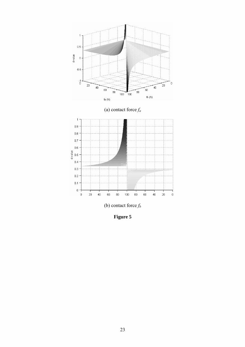
As shown in Eq. (12), dvalue is affected by contact forces fa and fb. Fig. 5 shows the changing behaviour of dvalue when misalignment angle θ between the links is positive. Therefore, a dvalue approach is established to distinguish between different contact states for a cylindrical pair according to dvalue. Null Contact In the situation of null contact, both M3 and F2 are zero. Therefore, rather than using dvalue which could approach a singularity under such a condition, the null contact type is identified by simply evaluating if both M3 and F2 are zero. This can be proven as follows: It is noted that F2 = 0 holds only if fa = fb or fa = fb = 0. Consider
0)(3 wtbtaba llflfRfRfM (13) Since M3 = 0, Eq. (13) can be further written as
7
Rl
Rll
f
f
t
wt
b
a
(14)
Eq. (14) represents the ratio between fa and fb, when M3 = 0. Obviously, under such a condition, we have fa ≠ fb. Therefore, both F2 and M3 approach zero only under a null contact situation. Single-Point Contact dvalue can also be utilised to identify a single point contact situation. Fig. 5 shows the variation of dvalue according to contact forces. It can be seen that dvalue = 0.2874 or dvalue = 0.3374 when fa = 0 or fb = 0, respectively. Therefore, one can intuitively deduce dvalue to be either lt or lt+lw since the contact points lie on one of the two outer link circumferential edges. Line Contact In the case of line contact, the resultant force due to the forces exerted between the links along the contact line is located between the two circumferential edges of the outer-link. Therefore, in such a case, there is lt < dvalue < lt + lw. Two-Point Contact As indicated earlier, in a two-point contact situation, neither fa nor fb is zero. In such a case, dvalue < lt or dvalue > lt + lw. This can be further verified from the plots depicted in Fig. 5. As shown in Fig. 5, when fa and fb are nonzero, dvalue < 0.2874 or dvalue > 0.3374. Given the fact that the line of action of the resultant force must lie outside the region between the contact forces, one can also establish the relevant range of dvalue. The relevant controller actions necessary to minimise contact forces between the links are identical to that described in the previous section. However, it should be noted that the sense of the misalignment cannot be determined by the dvalue in such a condition.
4. Comparison Analysis for dvalue and Force based Contact Type Identification Approaches From the previous sections, it can be seen that both the force based approach and the dvalue approach for contact state/type identification possess substantially different sensitivities to friction. In this section, these two approaches established for contact state/type identification are examined, highlighting the relative advantages and disadvantages particularly related to experimental issues. Based on this, a hybrid methodology is established for contact state identification by combining the inherent advantages of the two approaches. Experiments have been conducted to evaluate and analyse the friction effects for the two approaches. The nominal friction coefficient has been experimentally estimated to be 0.145. Fig. 6 describes the disparity in contact force fa when the friction coefficient deviates from the nominal value of 0.145. The actual value of contact force fa is in the range 0-100 N, and a single point contact situation has been considered in this analysis. Fig. 6(b) is an expanded version of Fig. 6(a) in the vicinity of µ = 0.145 to show the localised behaviour. The curves in Fig. 6 clearly indicate the high sensitivity of the estimated contact forces when the friction coefficient deviates from the nominal value. Since the contact type and the sense of orientation are determined by the derived contact forces, such deviations may cause erroneous contact type identification. In particular, when the actual friction coefficient is in the range 0 – 0.08, deviations associated with contact force fa are substantially large. Conversely, it can be seen that if the friction between the two links is high, the effect of friction coefficient deviations on the estimated contact forces is significantly low.
8
As evident from Eq. (11), the effect of friction coefficient deviations on dvalue is due to the term µR. In particular, for a relatively large dvalue, deviations due to friction are substantially low, since R is generally small. For the experimental setup in this study, the critical values of dvalue are 0.287 and 0.337, respectively. Fig. 7 depicts the variation of dvalue for a single point contact situation, where the nominal dvalue is 0.287 when µ = 0.145. It is evident that the variation of dvalue due to friction as shown in Fig. 7 is considerably lower than the contact force deviation as shown in Fig. 6. This clearly shows that the dvalue approach has a higher robustness for contact type identification. For a friction coefficient variation of 0.1 – 0.2, dvalue variation is only in the range 0.28633 – 0.28783. In theory, for a similar friction coefficient deviation, the contact force fa determined by the force based approach deviates from 27N to -17N. Although such robustness is highly beneficial, the dvalue approach alone is unable to determine the sense of orientation misalignment θ in the case of two-point contact for robotic control. By comparing the advantages and disadvantages of the two approaches, it is evident that the dvalue approach is the most appropriate solution for contact state identification. However, if the identified type of contact is a two-point contact, the force based approach is necessary to extract further information such as the sense of the misalignment and contact forces for robotic control.
5. Spatial Analysis in a Dynamic Environment Consider a setup consisting of a cylindrical pair outer link attached to a 6-DOF (Degrees of Freedom) manipulator and the inner link attached to a dynamic environment with three orthogonal translational DOF. The clearance between the inner and outer links is considered to be small. Consequently, in the case of two-point contact, it is assumed that the contact points and contact forces are on a plane coincident with the diameters of the inner and outer links. This plane also contains the Zp-axis and is referred to as the contact plane. The contact plane contains the point C and axis F1 at all times. The magnitude of the projection of the tilt angle or the misalignment between the outer link and inner link on the contact plane is θ. The angle between the contact plane and the reference frame axis Xp attached to the outer link is α, where the sense is positive when rotated about axis Zp. The rotation angle of the inner link about the F1 axis is β. This is evident as the angle between axis F2 and the contact plane. Friction forces due to relative translational and rotational motion links are always parallel or perpendicular to the Z-axis. A key difference between the current analysis and previous work [1, 6, 30, 31] is that tangential forces at contact points are considered in the spatial analysis due to the permitted rotation of the outer link about its axis. The forces at contact points, i.e. normal force, friction due to sliding and friction due to rotation, are considered to be orthogonal to each other. Fig. 8 describes the forces on the contact plane. Only Z and Zp axes are specified as the reference frames due to the possible rotation of the contact plane about axis Zp, and thus indicating that axis Xp does not always coincide with the contact plane. As shown in Fig. 8, the effective acceleration on the contact plane due to EX and EY is
)sincos( EE YX , where EX and EY are the acceleration components of the end-effector and are considered to be similar to those of the Cartesian manipulator along the Xp and Yp directions, respectively. By the D’Alembert’s principle, the contact forces may be written as

9
])sincos(
)sin(cos)cos)(sinsincos[(2
1132
eppp
a
ZmZmmgYXm
FFFf
(15)
and
])sincos(
)sin(cos)cos)(sinsincos[(2
1132
eppp
b
ZmZmmgYXm
FFFf
(16)
Since sinθ ≈ 0 and cosθ ≈ 1 when θ is very small, Eqs. (15) and (16) become as
))sincos(cossin(2
1123 epppa ZmZmmgYXmFFFf
(17)
and
))sincos(sincos(2
1132 epppb ZmZmmgYXmFFFf
(18)
Similar to the planar case, the contact state and the most appropriate controller action required to minimise contact forces cannot be determined solely from force data. Therefore, a force based approach similar to that in the planar case is established to identify the sense of the misalignment by using the values of fa and fb estimated by Eqs. (17) and (18). Due to the implicit nature of the contact forces and contact points, a vectorial representation of forces relative to the F/T sensor coordinate frame is utilised when determining the type of contact. The cross product is utilised to determine the moments cM1 , cM 2 and cM 3 about the F1-F2-F3 axes
due to the contact forces, friction and gravity. Let )(1 cM , )(2 cM and )(3 cM be the
calculated moments about axes F1, F2 and F3, respectively, due to a positive misalignment. These can be determined by manipulating the known contact forces, friction, and gravitational forces. Moments corresponding to a positive misalignment can be described as
FrM c )()(3,2,1 (19)
By Eq. (19), the following equations may be established
RffM bac )()(1 (20)
}cos)(sin)(sin{}sincossin{)(2 wtwtbtta
c llllRfRllfM (21) and
}sin)(cos)(cos{}sincoscos{)(3 wtwtbttac llllRflRlfM (22)
Let )(1 cM , )(2 cM and )(3 cM be the calculated moments due to a negative misalignment.
The calculated moments for a negative misalignment may be written as
10
FrM c )()(3,2,1 (23)
By Eq. (23), the following moment relations may be written
RffM bac )()(1 (24)
}sincossin{}sin)(cos)({)(2 ttbwtwta
c llRfRllllfM (25) and
}coscossin{}sin)(cos){()(3 ttbwtwtac lRlfllRllfM (26)
A comparison between )(1 cM and )(1 cM is redundant since both of these moment components are due to the tangential friction forces, and are independent of the misalignment sense. Therefore, the actual moments M2 and M3 measured by the wrist mounted F/T sensor are compared with the calculated moment components )(2 cM , )(2 cM , )(3 cM and )(3 cM to determine the sense
of the misalignment. For a positive misalignment, we have
)(22 cMM (27) and
)(33 cMM (28) where )(2 cM and )(3 cM are the calculated moments described by Eqs. (21) and (22).
Similarly, for a negative misalignment, we have
)(22 cMM (29) and
)(33 cMM (30) where )(2 cM and )(3 cM are the calculated moments as described by Eqs. (25) and (26).
The identification procedure which is based on the measured and calculated moments fails only if Eq. (31) or (32) is satisfied.
)()( 22 cc MM (31)
)()( 33 cc MM (32) Substituting Eqs. (21) and (25) into Eq. (31) as well as Eqs. (22) and (26) into Eq. (32), the following condition for the failure of identification may be written as

11
ba ff (33) It is impossible to satisfy the condition Eq. (33) unless sticking is present between the two links. Therefore, the established technique to determine the sense of orientation is valid for all possible values of contact forces. The dvalue approach for a dynamic environment has a similar process as that for a static environment. The dvalue can be represented by the resultant moment MR and force FR on the contact plane as
R
Rvalue F
MRd (34)
where
gEER lYXmFFF )sincos(sincos 32 (35)
and
gEER lYXmMMM )sincos(sincos 23 (36)
The dvalue principles for contact type determination in a dynamic environment are the same as those in a static environment. Further, similar to the case of a static environment, a hybrid methodology that combines the dvalue approach with the force based approach can also be established for contact state determination in a dynamic environment.
6. Experimental Results Experiments have been conducted to evaluate the performance of the proposed methodology. The experimental setup is shown in Fig. 9. It includes a Motoman SK-120 articulated robot manipulator, a JR3 F/T sensor attached to the wrist, an outer link attached to the F/T sensor and an inner link attached to a Cartesian manipulator. A laser-interferometry-based sensing and measurement system is utilised to detect the displacement of the Cartesian positioning mechanism. Such an experimental setup provides low measurement uncertainties and high accuracy and resolution, and is frequently used for tracking of dynamic systems [32-35]. Different contact types are introduced by the robot manipulator. During the experiments, the height adjustment is performed by maintaining the introduced contact states while simultaneously acquiring force/moment data. The acquired data is processed, and subsequently utilised in the formulations in order to determine the state of contact. Force/moment data is obtained at 500 Hz. The height is adjusted at a velocity of 2.5 mm/s. In order to minimise contact forces between a cylindrical pair, the correction action by the controller not only considers the magnitudes of forces and moments exerted between links, but also considers the type of contact between them. The contact state between a cylindrical pair can be determined by the proposed hybrid methodology. The proposed methodology employs the dvalue approach to distinguish between different contact types. If the type of contact between the links is a two-point contact, the force based approach is employed to determine parameters necessary for robotic control. With the proposed hybrid methodology, F/T sensor data can be utilised in the raw format to deduce the extent of the control action. The controller actions under different contact types between links are summarised in Table 1.
12
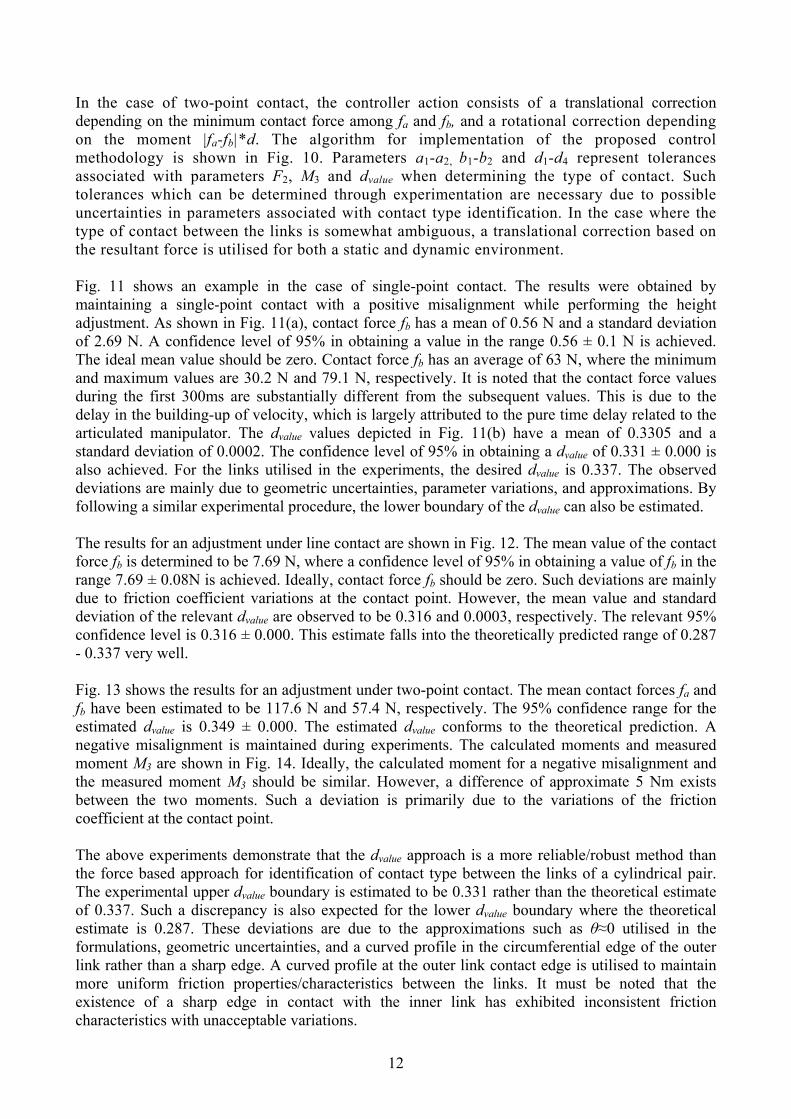
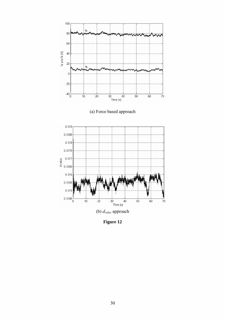
In the case of two-point contact, the controller action consists of a translational correction depending on the minimum contact force among fa and fb, and a rotational correction depending on the moment |fa-fb|*d. The algorithm for implementation of the proposed control methodology is shown in Fig. 10. Parameters a1-a2, b1-b2 and d1-d4 represent tolerances associated with parameters F2, M3 and dvalue when determining the type of contact. Such tolerances which can be determined through experimentation are necessary due to possible uncertainties in parameters associated with contact type identification. In the case where the type of contact between the links is somewhat ambiguous, a translational correction based on the resultant force is utilised for both a static and dynamic environment. Fig. 11 shows an example in the case of single-point contact. The results were obtained by maintaining a single-point contact with a positive misalignment while performing the height adjustment. As shown in Fig. 11(a), contact force fb has a mean of 0.56 N and a standard deviation of 2.69 N. A confidence level of 95% in obtaining a value in the range 0.56 ± 0.1 N is achieved. The ideal mean value should be zero. Contact force fb has an average of 63 N, where the minimum and maximum values are 30.2 N and 79.1 N, respectively. It is noted that the contact force values during the first 300ms are substantially different from the subsequent values. This is due to the delay in the building-up of velocity, which is largely attributed to the pure time delay related to the articulated manipulator. The dvalue values depicted in Fig. 11(b) have a mean of 0.3305 and a standard deviation of 0.0002. The confidence level of 95% in obtaining a dvalue of 0.331 ± 0.000 is also achieved. For the links utilised in the experiments, the desired dvalue is 0.337. The observed deviations are mainly due to geometric uncertainties, parameter variations, and approximations. By following a similar experimental procedure, the lower boundary of the dvalue can also be estimated. The results for an adjustment under line contact are shown in Fig. 12. The mean value of the contact force fb is determined to be 7.69 N, where a confidence level of 95% in obtaining a value of fb in the range 7.69 ± 0.08N is achieved. Ideally, contact force fb should be zero. Such deviations are mainly due to friction coefficient variations at the contact point. However, the mean value and standard deviation of the relevant dvalue are observed to be 0.316 and 0.0003, respectively. The relevant 95% confidence level is 0.316 ± 0.000. This estimate falls into the theoretically predicted range of 0.287 - 0.337 very well. Fig. 13 shows the results for an adjustment under two-point contact. The mean contact forces fa and fb have been estimated to be 117.6 N and 57.4 N, respectively. The 95% confidence range for the estimated dvalue is 0.349 ± 0.000. The estimated dvalue conforms to the theoretical prediction. A negative misalignment is maintained during experiments. The calculated moments and measured moment M3 are shown in Fig. 14. Ideally, the calculated moment for a negative misalignment and the measured moment M3 should be similar. However, a difference of approximate 5 Nm exists between the two moments. Such a deviation is primarily due to the variations of the friction coefficient at the contact point. The above experiments demonstrate that the dvalue approach is a more reliable/robust method than the force based approach for identification of contact type between the links of a cylindrical pair. The experimental upper dvalue boundary is estimated to be 0.331 rather than the theoretical estimate of 0.337. Such a discrepancy is also expected for the lower dvalue boundary where the theoretical estimate is 0.287. These deviations are due to the approximations such as θ≈0 utilised in the formulations, geometric uncertainties, and a curved profile in the circumferential edge of the outer link rather than a sharp edge. A curved profile at the outer link contact edge is utilised to maintain more uniform friction properties/characteristics between the links. It must be noted that the existence of a sharp edge in contact with the inner link has exhibited inconsistent friction characteristics with unacceptable variations.

13
It is evident that the identification of a line contact situation by the dvalue approach is more effective than the force based approach. Although experiments have demonstrated that the dvalue approach is capable of identifying two-point contact, utilisation of the parameters determined by the force based approach is essential for verifying the sense of the misalignment and extracting force information for control actions of orientation and translation by the articulated robot.
7. Conclusions This paper presented a comprehensive study for robotic-based height adjustment of a cylindrical pair based on maintaining minimum contact forces between the links. The environment which holds the inner link can be fixed in space or in motion along the X-Y-Z directions. A force based approach and a dvalue approach were established to determine the type of contact between the links and extract parameters for robotic control from both planar and spatial points of view under both static and dynamic environmental conditions. The comprehensive comparison and analysis of these two methods were conducted, showing that the force based approach is highly sensitive to friction variations at the contact point, whereas the dvalue approach is more robust except for the inability to determine the sense of the misalignment between the links. Based on the comparison and analysis, a hybrid methodology was established by combining these two approaches to identify the underlying contact state between a cylindrical pair subjected to a height adjustment manipulation. This hybrid methodology utilises the dvalue approach to determine the type of contact. If the type of contact is a two-point contact, the force based approach is subsequently employed to extract necessary parameters for robotic control. Experimental results demonstrated that the hybrid methodology can effective identify the type of contact and utilise this knowledge to maintain minimum contact forces for the height adjustment of a cylindrical pair. Discrepancies between the theoretical predictions and the experimental results were predominantly attributed to friction coefficient deviations at contact points.
Acknowledgements This study has been partly supported by Australian Research Council (ARC) Linkage project (project number: LP0455753).
References [1] P. De Waas Tilakaratna, B. Shirinzadeh and G. Alici, Contact Type Determination for Cylindrical Pair Adjustment, Proceeding of the IEEE/ASME International Conference on Advance Intelligent Mechatronics, Kobe, Japan, 2003, pp. 326-331. [2] M. Klingajay, L. D. Seneviratne and K. Althoefer, Identification of Threaded Fastening Parameters using the Newton Raphson Method, Proceedings of the IEEE/RSJ International Conference on Intelligent Robots and Systems, Las Vegas, USA, 2003, pp. 2055-2060. [3] M. T. Mason, Mechanics and Planning of Manipulator Pushing Operations, The International Journal of Robotics Research, Vol. 5, No. 3, 1986, pp. 53-71. [4] E. J. Nicolson and R. S. Fearing, Compliant Control of Threaded Fastener Insertion, Proceedings of the IEEE International Conference on Robotics and Automation, Atlanta, USA, 1993, pp. 484-490. [5] M. A. Peshkin and A. C. Sanderson, Manipulation of a Sliding Object, Proceedings of the IEEE International Conference on Robotics and Automation, San Francisco, USA, 1986, pp. 233-239.
14
[6] Y. L. Shen and B. Shirinzadeh, Dynamic Analysis of Reconfigurable Fixture Construction by a Manipulator, Robotics and Computer Integrated Manufacturing, Vol. 17, No. 5, 2001, pp. 367-377. [7] M. Brokowski, M. Peshkin, and K. Goldberg, Optimal Curved Fences for Part Alignment on a Belt, Transactions of the ASME Journal of Mechanical Design, Vol. 117, No. 1, 1995, pp. 27-35. [8] M. A. Peshkin and A. C. Sanderson, The Motion of a Push Sliding Workpiece, IEEE Journal of Robotics and Automation, Vol. 4, No. 6, 1988, pp. 569-598. [9] M. A. Peshkin and A. C. Sanderson, Planning Robotic Manipulations Strategies for Workpieces, IEEE Journal of Robotics and Automation, Vol. 4, No. 5, 1988, 524-531. [10] S. Rusaw, K. Gupta and S. Payandeh, Flexible Part Orienting Using Rotation Direction and Force Measurements, International Journal of Robotics Research, Vol. 20, No. 6, 2001, pp. 484-505. [11] S. Rusaw, K. Gupta and S. Payandeh, Orienting Polygons with Fences Over a Conveyor Belt: Empirical Observations, Proceedings of the IEEE/RSJ International Conference on Intelligent Robots and Systems, Victoria, Canada, 1998, pp. 831-836. [12] S. Rusaw, K. Gupta and S. Payandeh, Part Orienting with a Force/Torque Sensor, Proceedings of the IEEE International Conference on Robotics and Automation, Detroit, USA, 1999, pp. 2545-2550. [13] T. Lefebvre, H. Bruyninckx, J. De Schutter, Polyhedral contact formation modeling and identification for autonomous compliant motion, IEEE Transactions on Robotics and Automation, Vol. 19, No. 3, 2003, pp26-41. [14] T. Lefebvre, H. Bruyninckx, J. De Schutter, Polyhedral contact formation identification for autonomous compliant motion: exact nonlinear Bayesian filtering, IEEE Transactions on Robotics and Automation, Vol. 21, No. 1, 2005, pp124–129. [15] K. Gadeyne, T. Lefebvre, H. Bruyninck, Bayesian Hybrid Model-State Estimation Applied to Simultaneous Contact Formation Recognition and Geometrical Parameter Estimation, The International Journal of Robotics Research, Vol. 24, No. 8, 2005, pp615-630. [16] M. Klingajay, L. D. Seneviratne and K. Althoefer, Parameter Estimation During Automated Screw Insertions, Proceedings of the IEEE International Conference on Industrial Technology, Bangkok, Thailand, 2002, pp. 1019-1024. [17] L. D. Seneviratne, P. Visuwan and K. Althoefer, Weightless Neural Network Based Monitoring of Screw Fastenings, Proceedings of the IEEE/RSJ International Conference on Intelligent Robots and Systems, Kyongju, South Korea, 1999, pp. 561-566. [18] B. Shirinzadeh, Flexible and Automated Workholding Systems, Industrial Robot, Vol. 22, No. 2, 1995, pp. 29-34. [19] R. C. Brost and K. Y. Goldberg, A Complete Algorithm for Designing Planar Fixtures Using Modular Components, IEEE Transactions on Robotics and Automation, Vol. 12, No. 1, 1996, pp. 31-46. [20] A. S. Wallack and J. F. Canny, Planning for Modular and Hybrid Fixtures, Algorithmica, Vol. 19, No. 1-2, 1997, pp. 40-60. [21] B. Shirinzadeh and Y. Tie, Experimental Investigation of the Performance of a Reconfigurable Fixturing System, International Journal of Advanced Manufacturing Technology, Vol. 10, No. 5, 1995, pp. 330-341. [22] H. H. Asada and A. H. By, Kinematic Analysis and Design for Automatic Workpart Fixturing Assembly, Proceedings of the 2nd International Symposium of Robotics Research, Kyoto, Japan, 1985, pp. 237-244. [23] B. Shirinzadeh, Flexible Fixturing for Workpiece Positioning and Constraining, Assembly Automation, Vol. 22, No. 2, 2002, pp. 112-120. [24] W. H. Qian and H. Qiao, An Efficient Algorithm for Computing Object Poses in A Modular Fixture or Gripper, Journal of Robotic Systems, Vol. 19, No. 3, 2002, pp. 99-114. [25] B. Shirinzadeh, CAD-based Design and Analysis System for Reconfigurable Fixtures in Robotic Assembly, Computing & Control Engineering Journal, Vol. 5, No. 1, 1994, pp. 41-46.

15
[26] K R. Wardak, U. Tasch and R. Charalambides, Optimal Fixture Design for Drilling Through Deformable Plate Workpieces- Part I: Model Formulation, Journal of Manufacturing Systems, Vol. 20, No. 1, 2001, pp. 23-32. [27] B. Shirinzadeh, A CAD-based Hierarchical Approach to Interference Detection Among Fixture Modules in a Reconfigurable Fixturing System, Journal of Robotics & Computer-Integrated Manufacturing, Vol. 12, No.1, 1996, pp. 41-53. [28] A. Sudsang, J. Ponce and N. Srinivasa, Grasping and In-hand Manipulation: Geometry and Algorithm, Algorithmica, Vol. 26, No. 3-4, 2000, pp. 466-493. [29] B. Shirinzadeh, Issues in the Design of the Reconfigurable Fixture Modules for Robotic Assembly, Journal of Manufacturing Systems, Vol. 12, No. 1, 1993, pp. 1-14. [30] H. Zohoor and M. Shahinpoor, Dynamic Analysis of Peg-In-Hole Insertion for Manufacturing Automation, Journal of Manufacturing Systems, Vol. 10, No. 2, 1991, pp. 99-108. [31] P. De Waas Tilakaratna, B. Shirinzadeh and G. Alici, Experimental Investigation of 2D Cylindrical Pair Height Adjustment in a Static Environment, Proceedings of the 3rd IFAC Symposium on Mechatronic Systems, Sydney, Australia, 2004, pp. 663-668. [32] B. Shirinzadeh, Laser-interferometry-based Tracking for Dynamic Measurements, Industrial Robot: An International Journal, Vol. 25, No. 1, 1998, pp. 35-41. [33] P. L. Teoh, B. Shirinzadeh, C. W. Foong and G. Alici, The Measurement Uncertainties in Laser Interferometry-based Sensing and Tracking Technique, International Journal of Measurement, Vol.32, No. 2, 2002, pp. 135-150. [34] G. Alici and B. Shirinzadeh, Enhanced Stiffness Modelling, Identification and Characterisation for Robot Manipulators, IEEE Transactions on Robotics, Vol. 21, No. 4, 2005, pp. 554-564. [35] B. Shirinzadeh, P. L. Teoh, Y. Tian, M. M. Dalvand, Y. Zhong, H. C. Liaw, Laser interferometry-based Guidance Methodology for High Precision Positioning of Mechanisms and Robots, Robotics and Computer-Integrated Manufacturing, Vol. 26, No. 1, 2010, pp. 74-82.

16
Table Captions
Table 1. Types of contact between links and relevant controller actions

17
Table 1
Types of Contact Controller Actions Null contact None
Single-point contact Translational adjustmentLine contact Translational adjustment
Two-point contact Translational + Rotational adjustment
18
Figure Captions Figure 1. Schematic diagram of experimental setup
Figure 2. Planar force analysis diagram
Figure 3. Deviations in fa and fb under the assumption of θ ≈ 0o
Figure 4. Cylindrical pair’s link representation for a planar static case
Figure 5. Variation of dvalue with contact forces fa and fb
Figure 6. Deviation of contact force fa with the friction coefficient
Figure 7. dvalue variation with the friction coefficient
Figure 8. Forces in the contact plane - 3D dynamic case
Figure 9. Experimental setup
Figure 10. Algorithm flowchart
Figure 11. Contact forces during single-point contact
Figure 12. Contact forces during line contact
Figure 13. Contact forces during two-point contact
Figure 14. Calculated and measured moments

19
y
zx
Platform
ArticulatedManipulator
F/T Sensor
Outer Link Inner Link
Figure 1
20
F2
F1
M3
mg
fb
fafa
fbR
lg
lt
lw
2r
O
xp
zp
x
z
C
motion
ze
xe
A
B
Figure 2
21
(a) Deviation in fa
(b) Deviation in fb
Figure 3

22
d
M3F2
F1
fa
mg
fam
2R fbfbm
fresultant
Figure 4
23
(a) contact force fa
(b) contact force fb
Figure 5

24
(a) Friction coefficient range 0-1
(b) Friction coefficient range 0-0.2
Figure 6

25
Figure 7

26
F2cosß
F1
mg
fb
fafa
fbR
lg
lt
lw
2r
O
zpz
C
motion
ze
A
B
F3sinß
sincos....
EE YX
Figure 8

27
Figure 9

28
Figure 10

29
(a) Force based approach
(b) dvalue approach
Figure 11
30
(a) Force based approach
(b) dvalue approach
Figure 12

31
(a) Force based approach
(b) dvalue approach
Figure 13

32
Figure 14