a hybrid-statcom with wide compensation range and...
TRANSCRIPT
0278-0046 (c) 2015 IEEE. Personal use is permitted, but republication/redistribution requires IEEE permission. See http://www.ieee.org/publications_standards/publications/rights/index.html for more information.
This article has been accepted for publication in a future issue of this journal, but has not been fully edited. Content may change prior to final publication. Citation information: DOI 10.1109/TIE.2016.2523922, IEEETransactions on Industrial Electronics
IEEE TRANSACTIONS ON INDUSTRIAL ELECTRONICS 1
Abstract—This paper proposes a hybrid static synchronous
compensator (hybrid-STATCOM) in a three-phase power
transmission system that has a wide compensation range and low
DC-link voltage. Because of these prominent characteristics, the
system costs can be greatly reduced. In this paper, the circuit
configuration of hybrid-STATCOM is introduced first. Its V-I
characteristic is then analyzed, discussed, and compared with
traditional STATCOM and capacitive-coupled STATCOM
(C-STATCOM). The system parameter design is then proposed
on the basis of consideration of the reactive power compensation
range and avoidance of the potential resonance problem. After
that, a control strategy for hybrid-STATCOM is proposed to
allow operation under different voltage and current conditions,
such as unbalanced current, voltage dip, and voltage fault. Finally,
simulation and experimental results are provided to verify the
wide compensation range and low DC-link voltage characteristics
and the good dynamic performance of the proposed
hybrid-STATCOM.
Index Terms—Capacitive-coupled static synchronous
compensator (C-STATCOM), hybrid static synchronous
compensator (hybrid-STATCOM), static synchronous
compensator (STATCOM), wide compensation range, low
DC-link voltage
I. INTRODUCTION
HE large reactive current in transmission systems is one
of the most common power problems that increases
transmission losses and lowers the stability of a power system
[1]-[19]. Application of reactive power compensators is one of
the solutions for this issue.
Static VAR compensators (SVCs) are traditionally used to
dynamically compensate reactive currents as the loads vary
from time to time. However, SVCs suffer from many problems,
such as resonance problems, harmonic current injection, and
slow response [2]-[3]. To overcome these disadvantages, static
synchronous compensators (STATCOMs) and active power
Manuscript received June 13, 2015; revised October 02, 2015 and November
21, 2015; accepted December 23, 2015. Copyright © 2016 IEEE. Personal use of this material is permitted. However,
permission to use this material for any other purposes must be obtained from the IEEE by sending a request to [email protected].
This work was supported by Macau Science and Technology Development Fund (FDCT) (FDCT 109/2013/A3) and the Research Committee of University of Macau (MRG012/WMC/2015/FST, MYRG2015-00030-AMSV).
Lei Wang is with the Department of Electrical and Computer Engineering, Faculty of Science and Technology, University of Macau, Macao, China (e-mail: [email protected]).
C.-S. Lam and M.-C. Wong are with the Department of Electrical and Computer Engineering, Faculty of Science and Technology and State Key Laboratory of Analog and Mixed Signal VLSI, University of Macau, Macao, China. C.-S. Lam is the corresponding author (e-mail: [email protected], [email protected]; [email protected]).
filters (APFs) were developed for reactive current
compensation with faster response, less harmonic current
injection, and better performance [4]-[9]. However, the
STATCOMs or APFs usually require multilevel structures in a
medium- or high-voltage level transmission system to reduce
the high-voltage stress across each power switch and DC-link
capacitor, which drives up the initial and operational costs of
the system and also increases the control complexity. Later,
series-type capacitive-coupled STATCOMs (C-STATCOMs)
were proposed to reduce the system DC-link operating voltage
requirement [10], and other series-type hybrid structures that
consist of different passive power filters (PPFs) in series with
STATCOMs or APF structures (PPF-STATCOMs) have been
applied to power distribution systems [11]-[16] and traction
power systems [17]-[19]. However, C-STATCOMs and other
series-type PPF-STATCOMs contain relatively narrow
reactive power compensation ranges. When the required
compensating reactive power is outside their compensation
ranges, their system performances can significantly deteriorate.
To improve the operating performances of the traditional
STATCOMs, C-STATCOMs, and other PPF-STATCOMs,
many different control techniques have been proposed, such as
the instantaneous p-q theory [4], [10], [11], [17]-[19], the
instantaneous d-q theory [5], [6], [14], the instantaneous id-iq
method [7], negative- and zero-sequence control [8], the back
propagation (BP) control method [9], nonlinear control [12],
Lyapunov-function-based control [13], instantaneous
symmetrical component theory [15], and hybrid voltage and
current control [16].
To reduce the current rating of the STATCOMs or APFs, a
hybrid combination structure of PPF in parallel with
STATCOM (PPF// STATCOM) was proposed in [20] and [21].
However, this hybrid compensator is dedicated for inductive
loading operation. When it is applied for capacitive loading
compensation, it easily loses its small active inverter rating
characteristics. To enlarge the compensation range and keep
low current rating characteristic of the APF, Dixon et al. [22]
proposed another hybrid combination structure of SVC in
parallel with APF (SVC//APF) in three-phase distribution
systems. In this hybrid structure, the APF is controlled to
eliminate the harmonics and compensate for the small amounts
of load reactive and unbalanced power left by the SVC.
However, if this structure is applied in a medium- or
high-voltage level transmission system, the APF still requires a
costly voltage step-down transformer and/or multilevel
structure. In addition, these two parallel connected-hybrid
STATCOM structures [15]-[17] may suffer from a resonance
problem.
Lei Wang, Chi-Seng Lam, Member, IEEE, and Man-Chung Wong, Senior Member, IEEE
A Hybrid-STATCOM with Wide Compensation Range and Low DC-Link Voltage
T
0278-0046 (c) 2015 IEEE. Personal use is permitted, but republication/redistribution requires IEEE permission. See http://www.ieee.org/publications_standards/publications/rights/index.html for more information.
This article has been accepted for publication in a future issue of this journal, but has not been fully edited. Content may change prior to final publication. Citation information: DOI 10.1109/TIE.2016.2523922, IEEETransactions on Industrial Electronics
IEEE TRANSACTIONS ON INDUSTRIAL ELECTRONICS 2
To overcome the shortcomings of different reactive power
compensators [1]-[22] for transmission systems, this paper
proposes a hybrid-STATCOM that consists of a
thyristor-controlled LC part (TCLC) and an active inverter part,
as shown in Fig. 1. The TCLC part provides a wide reactive
power compensation range and a large voltage drop between
the system voltage and the inverter voltage so that the active
inverter part can continue to operate at a low DC-link voltage
level. The small rating of the active inverter part is used to
improve the performances of the TCLC part by absorbing the
harmonic currents generated by the TCLC part, avoiding
mistuning of the firing angles, and preventing the resonance
problem. The contributions of this paper are summarized as
follows.
A hybrid-STATCOM is proposed, with the distinctive
characteristics of a much wider compensation range than
C-STATCOM [10] and other series-type PPF-STATCOMs
[11]-[19] and a much lower DC-link voltage than traditional
STATCOM [4]-[9] and other parallel-connected hybrid
STATCOMs [20]-[22].
Its V-I characteristic is analyzed to provide a clear view of
the advantages of hybrid-STATCOM in comparison with
traditional STATCOM and C-STATCOM.
Its parameter design method is proposed based on
consideration of the reactive power compensation range,
prevention of the potential resonance problem and
avoidance of mistuning of firing angle.
A new control strategy for hybrid-STATCOM is proposed
to coordinate the TCLC part and the active inverter part for
reactive power compensation under different voltage and
current conditions, such as unbalanced current, voltage fault,
and voltage dip.
The characteristics of different reactive power
compensators and the proposed hybrid-STATCOM for the
transmission system are compared and summarized in Table I.
TABLE I
CHARACTERISTICS OF DIFFERENT COMPENSATORS FOR TRANSMISSION
SYSTEM
Response
time Resonance
problem DC-link voltage
Compensation range
Cost
SVCs [2]-[3] Slow Yes -- Wide Low
STATCOMs [4]-[9]
Very Fast
No High Wide High
C-STATCOMs [10] Fast No Low Narrow Low
Series-type PPF-STATCOMs
[11]-[19] Fast No Low Narrow Low
PPF//STATCOM [20], [21]
Fast Yes High Narrow Medium
SVC//APF [22] Fast Yes High Wide High
Hybrid-STATCOM Fast No Low Wide Medium
*Shaded areas indicate an unfavorable characteristic.
In this paper, the system configuration of the proposed
hybrid-STATCOM is introduced in section II. In section III, the
V-I characteristic of hybrid-STATCOM is proposed in
comparison with traditional STATCOM and C-STATCOM.
The parameter design and control strategy of the
hybrid-STATCOM are then proposed in Sections IV and V.
Finally, the simulation (Section VI) and experimental results
(Section VII) are provided to prove the wide compensation
range and low DC-link voltage characteristics and the dynamic
performance of the proposed hybrid-STATCOM.
II. CIRCUIT CONFIGURATION OF THE HYBRID-STATCOM
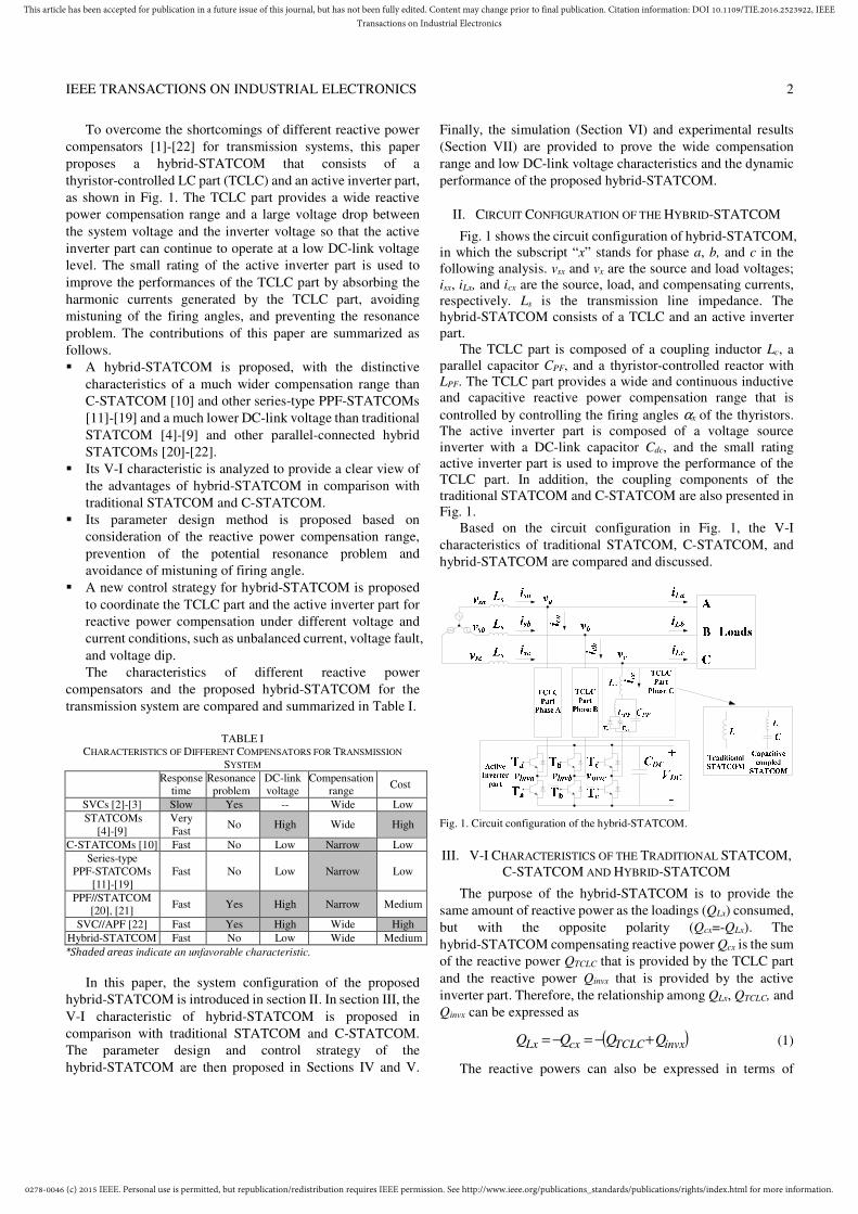
Fig. 1 shows the circuit configuration of hybrid-STATCOM, in which the subscript “x” stands for phase a, b, and c in the following analysis. vsx and vx are the source and load voltages; isx, iLx, and icx are the source, load, and compensating currents, respectively. Ls is the transmission line impedance. The hybrid-STATCOM consists of a TCLC and an active inverter part.
The TCLC part is composed of a coupling inductor Lc, a parallel capacitor CPF, and a thyristor-controlled reactor with
LPF. The TCLC part provides a wide and continuous inductive and capacitive reactive power compensation range that is
controlled by controlling the firing angles αx of the thyristors. The active inverter part is composed of a voltage source inverter with a DC-link capacitor Cdc, and the small rating active inverter part is used to improve the performance of the TCLC part. In addition, the coupling components of the traditional STATCOM and C-STATCOM are also presented in Fig. 1.
Based on the circuit configuration in Fig. 1, the V-I
characteristics of traditional STATCOM, C-STATCOM, and
hybrid-STATCOM are compared and discussed.
Fig. 1. Circuit configuration of the hybrid-STATCOM.
III. V-I CHARACTERISTICS OF THE TRADITIONAL STATCOM, C-STATCOM AND HYBRID-STATCOM
The purpose of the hybrid-STATCOM is to provide the
same amount of reactive power as the loadings (QLx) consumed,
but with the opposite polarity (Qcx=-QLx). The
hybrid-STATCOM compensating reactive power Qcx is the sum
of the reactive power QTCLC that is provided by the TCLC part
and the reactive power Qinvx that is provided by the active
inverter part. Therefore, the relationship among QLx, QTCLC, and
Qinvx can be expressed as
( )invxTCLCcxLx QQQQ +−=−= (1)
The reactive powers can also be expressed in terms of
0278-0046 (c) 2015 IEEE. Personal use is permitted, but republication/redistribution requires IEEE permission. See http://www.ieee.org/publications_standards/publications/rights/index.html for more information.
This article has been accepted for publication in a future issue of this journal, but has not been fully edited. Content may change prior to final publication. Citation information: DOI 10.1109/TIE.2016.2523922, IEEETransactions on Industrial Electronics
IEEE TRANSACTIONS ON INDUSTRIAL ELECTRONICS 3
voltages and currents as
( )cqxinvx2cqxxTCLCLqxxLx IVI)(XIVQ +−== α (2)
where XTCLC(αx) is the coupling impedance of the TCLC part;
αx is the corresponding firing angle; Vx and Vinvx are the root
mean square (RMS) values of the coupling point and the
inverter voltages; and ILqx and Icqx are the RMS value of the load
and compensating reactive currents, where ILqx=-Icqx. Therefore,
(2) can be further simplified as
LqxxTCLCxinvx I)(XVV α+= (3)
where the TCLC part impedance XTCLC(αx) can be expressed as
c
PFPF
PFPF
c
PF
PFL
LxxC
CLL
xTCRC
CxTCRxTCLC X
X)2sin22(X
XXX
)(XX
X)(X)(X +
−+−=+
−=
πααπ
π
α
αα
(4)
where cLX ,
PFLX , and PFCX are the fundamental impedances
of Lc, LPF, and CPF, respectively. In (4), it is shown that the
TCLC part impedance is controlled by firing angle αx. And the
minimum inductive and capacitive impedances (absolute value)
of the TCLC part can be obtained by substituting the firing
angles αx=90o and αx=180o, respectively. In the following
discussion, the minimum value for impedances stands for its
absolute value. The minimum inductive (Xind(min)>0) and
capacitive (XCap(min)<0) TCLC part impedances can be
expressed as
c
PFPF
PFPFL
LC
CLx(min)Ind X
XX
XX)90(X +
−=°=α (5)
cPF LCx(min)Cap XX )180(X +−=°=α (6)
Ideally, XTCLC(αx) is controlled to be LqxxTCLCx I)(XV α≈ , so
that the minimum inverter voltage ( 0Vinvx ≈ ) can be obtained
as shown in (3). In this case, the switching loss and switching
noise can be significantly reduced. A small inverter voltage
Vinvx(min) is necessary to absorb the harmonic current generated
by the TCLC part, to prevent a resonance problem, and to avoid
mistuning the firing angles. If the loading capacitive current or
inductive current is outside the TCLC part compensating range,
the inverter voltage Vinvx will be slightly increased to further
enlarge the compensation range.
The coupling impedances for traditional STATCOM and
C-STATCOM, as shown in Fig. 1, are fixed as XL and XC-1/XL.
The relationships among the load voltage Vx, the inverter
voltage Vinvx, the load reactive current ILqx, and the coupling
impedance of traditional STATCOM and C-STATCOM can be
expressed as
LqxLxinvx IXVV += (7)
LqxL
Cxinvx I)X
1X(VV −−= (8)
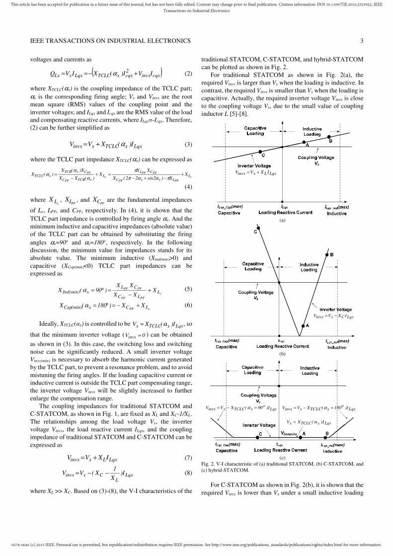
where XL >> XC. Based on (3)-(8), the V-I characteristics of the
traditional STATCOM, C-STATCOM, and hybrid-STATCOM
can be plotted as shown in Fig. 2.
For traditional STATCOM as shown in Fig. 2(a), the
required Vinvx is larger than Vx when the loading is inductive. In
contrast, the required Vinvx is smaller than Vx when the loading is
capacitive. Actually, the required inverter voltage Vinvx is close
to the coupling voltage Vx, due to the small value of coupling
inductor L [5]-[8].
LqxLxinvx IXVV +=
(a)
LqxCxinvx IXVV −=
(b)
LqxxTCLCx I)(XV α≈
Lqxo
xTCLCxinvx I)90(XVV =−= α Lqxo
xTCLCxinvx I)180(XVV =−= α
(c)
Fig. 2. V-I characteristic of (a) traditional STATCOM, (b) C-STATCOM, and
(c) hybrid-STATCOM.
For C-STATCOM as shown in Fig. 2(b), it is shown that the
required Vinvx is lower than Vx under a small inductive loading

0278-0046 (c) 2015 IEEE. Personal use is permitted, but republication/redistribution requires IEEE permission. See http://www.ieee.org/publications_standards/publications/rights/index.html for more information.
This article has been accepted for publication in a future issue of this journal, but has not been fully edited. Content may change prior to final publication. Citation information: DOI 10.1109/TIE.2016.2523922, IEEETransactions on Industrial Electronics
IEEE TRANSACTIONS ON INDUSTRIAL ELECTRONICS 4
range. The required Vinvx can be as low as zero when the
coupling capacitor can fully compensate for the loading
reactive current. In contrast, Vinvx is larger than Vx when the
loading is capacitive or outside its small inductive loading
range. Therefore, when the loading reactive current is outside
its designed inductive range, the required Vinvx can be very
large.
For the proposed hybrid-STATCOM as shown in Fig. 2(c),
the required Vinvx can be maintained at a low (minimum) level
(Vinvx(min)) for a large inductive and capacitive reactive current
range. Moreover, when the loading reactive current is outside
the compensation range of the TCLC part, the Vinvx will be
slightly increased to further enlarge the compensating range.
Compared with traditional STATCOM and C-STATCOM, the
proposed hybrid-STATCOM has a superior V-I characteristic
of a large compensation range with a low inverter voltage.
In addition, three cases represented by points A, B, and C in
Fig. 2 are simulated in Section VI. Based on Fig. 1, the
parameter design of hybrid-STATCOM is discussed in the
following section.
IV. PARAMETER DESIGN OF HYBRID-STATCOM
The proposed TCLC part is a newly proposed SVC
structure which designed based on the basis of the
consideration of the reactive power compensation range (for
LPF and CPF) and the prevention of the potential resonance
problem (for Lc). The active inverter part (DC-link voltage VDC)
is designed to avoid mistuning of the firing angle of TCLC part.
A. Design of CPF and LPF
The purpose of the TCLC part is to provide the same
amount of compensating reactive power Qcx,TCLC(αx) as the
reactive power required by the loads QLx but with the opposite
direction. Therefore, CPF and LPF are designed on the basis of
the maximum capacitive and inductive reactive power. The
compensating reactive power Qcx range in term of TCLC
impedance XTCLC(αx) can be expressed as
)(X
V)(Q
xTCLC
2x
xTCLC,cxα
α = (9)
where Vx is the RMS value of the load voltage and XTCLC(αx) is
the impedance of the TCLC part, which can be obtained from
(4). In (9), when the XTCLC(αx)=XCap(min)(αx =180ο) and
XTCLC(αx)=XInd(min)(αx =90ο), the TCLC part provides the
maximum capacitive and inductive compensating reactive
power Qcx(MaxCap) and Qcx(MaxInd), respectively.
cPF LC
2x
x(min)Cap
2x
)MaxCap(cxXX
V
)180(X
VQ
−−=
°==
α (10)
c
PFPF
PFPFL
LC
CL
2x
x(min)Ind
2x
)MaxInd(cx
XXX
XX
V
)90(X
VQ
+−
=°=
=α
(11)
where the minimum inductive impendence XInd(min) and the
capacitive impendence XCap(min) are obtained from (5) and (6),
respectively.
To compensate for the load reactive power (Qcx =- QLx), CPF
and LPF can be deduced on the basis of the loading maximum
inductive reactive power QLx(MaxInd) (=-Qcx(MaxCap)) and
capacitive reactive power QLx(MaxCap) (=-Qcx(MaxInd)). Therefore,
based on (10) and (11), the parallel capacitor CPF and inductor
LPF can be designed as
2xc)MaxInd(Lx
2
)MaxInd(LxPF
VLQ
QC
ωω += (12)
PF2x
2)MaxCap(LxPFc
3)MaxCap(Lx
)MaxCap(Lxc2x
PFCVQCLQ
QLVL
ωωω
ω
++−
+=
(13)
where ω is the fundamental angular frequency and Vx is the
RMS load voltage.
B. Design of Lc
For exciting resonance problems, a sufficient level of
harmonic source voltages or currents must be present at or near
the resonant frequency. Therefore, Lc can be designed to tune
the resonance points to diverge from the dominated harmonic
orders 1n6nd ±= th (n=1, 2, 3…) of a three-phase three-wire
transmission system to avoid the resonance problem.
The thyristors (Tx1 and Tx2) for each phase of the TCLC part
can be considered as a pair of bidirectional switches that
generate low-order harmonic currents when the switches
change states. The simplified single-phase equivalent circuit
model of hybrid-STATCOM is shown in Fig. 3.
Fig. 3. Simplified single-phase equivalent circuit model of hybrid-STATCOM.
Referring to Fig. 3, when switch S is turned off, the TCLC
part can be considered as the Lc in series with CPF, which is
called LC-mode. In contrast, when switch S is turned on, the
TCLC can be considered as the Lc in series with the
combination of CPF in parallel with LPF, which is called
LCL-mode. From Table IV in the Appendix A, the TCLC part
harmonic impedances under LC-mode and LCL-mode at
different harmonic order n can be plotted in Fig. 4 and
expressed as
( )
PF
PFC2
n,LCCn
CLn1)n(X
ω
ω−= (14)
( )
( ) PFPF2
PFcPF3
PFcn,LCL
CLn1
CLLn)LL(n)n(X
ω
ωω
−
−+= (15)
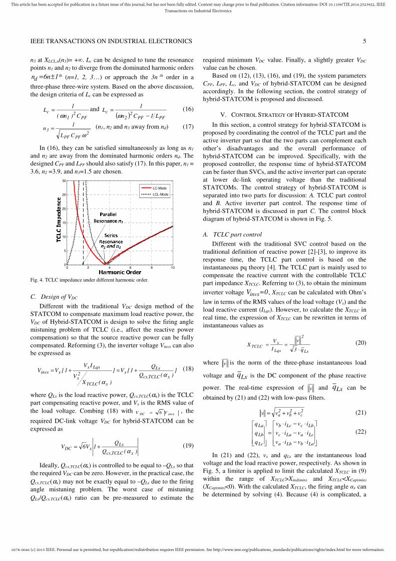
In (14) and (15), there are two series resonance points n1 at
XLC,n(n1)=0 and n2 at XLCL,n(n2)=0 and a parallel resonance point
0278-0046 (c) 2015 IEEE. Personal use is permitted, but republication/redistribution requires IEEE permission. See http://www.ieee.org/publications_standards/publications/rights/index.html for more information.
This article has been accepted for publication in a future issue of this journal, but has not been fully edited. Content may change prior to final publication. Citation information: DOI 10.1109/TIE.2016.2523922, IEEETransactions on Industrial Electronics
IEEE TRANSACTIONS ON INDUSTRIAL ELECTRONICS 5
n3 at XLCL,n(n3)= +∞. Lc can be designed to tune the resonance
points n1 and n2 to diverge from the dominated harmonic orders
1n6nd ±= th (n=1, 2, 3…) or approach the 3n th order in a
three-phase three-wire system. Based on the above discussion,
the design criteria of Lc can be expressed as
PF2
1
cC)n(
1L
ω= and
( ) PFPF2
2
cL1Cn
1L
−=
ω (16)
2PFPF
3
CL
1n
ω= (n1, n2 and n3 away from nd) (17)
In (16), they can be satisfied simultaneously as long as n1
and n2 are away from the dominated harmonic orders nd. The
designed CPF and LPF should also satisfy (17). In this paper, n1 =
3.6, n2 =3.9, and n3=1.5 are chosen.
0 2 4 6 8 100
5
10
15
20
25
30
LC-Mode
LCL-Mode
Fig. 4. TCLC impedance under different harmonic order.
C. Design of VDC
Different with the traditional VDC design method of the
STATCOM to compensate maximum load reactive power, the
VDC of Hybrid-STATCOM is design to solve the firing angle
mistuning problem of TCLC (i.e., affect the reactive power
compensation) so that the source reactive power can be fully
compensated. Reforming (3), the inverter voltage Vinvx can also
be expressed as
])(Q
Q1[V]
)(XV
IV1[VV
xTCLC,cx
Lxx
xTCLC
2x
Lqxxxinvx
αα
+=+= (18)
where QLx is the load reactive power, Qcx,TCLC(αx) is the TCLC
part compensating reactive power, and Vx is the RMS value of
the load voltage. Combing (18) with invxDC V6V = , the
required DC-link voltage VDC for hybrid-STATCOM can be
expressed as
)(Q
Q1V6V
xTCLC,cx
LxxDC
α+= (19)
Ideally, Qcx,TCLC(αx) is controlled to be equal to –QLx so that
the required VDC can be zero. However, in the practical case, the
Qcx,TCLC(αx) may not be exactly equal to –QLx due to the firing
angle mistuning problem. The worst case of mistuning
QLx/Qcx,TCLC(αx) ratio can be pre-measured to estimate the
required minimum VDC value. Finally, a slightly greater VDC
value can be chosen.
Based on (12), (13), (16), and (19), the system parameters
CPF, LPF, Lc, and VDC of hybrid-STATCOM can be designed
accordingly. In the following section, the control strategy of
hybrid-STATCOM is proposed and discussed.
V. CONTROL STRATEGY OF HYBRID-STATCOM
In this section, a control strategy for hybrid-STATCOM is
proposed by coordinating the control of the TCLC part and the
active inverter part so that the two parts can complement each
other’s disadvantages and the overall performance of
hybrid-STATCOM can be improved. Specifically, with the
proposed controller, the response time of hybrid-STATCOM
can be faster than SVCs, and the active inverter part can operate
at lower dc-link operating voltage than the traditional
STATCOMs. The control strategy of hybrid-STATCOM is
separated into two parts for discussion: A. TCLC part control
and B. Active inverter part control. The response time of
hybrid-STATCOM is discussed in part C. The control block
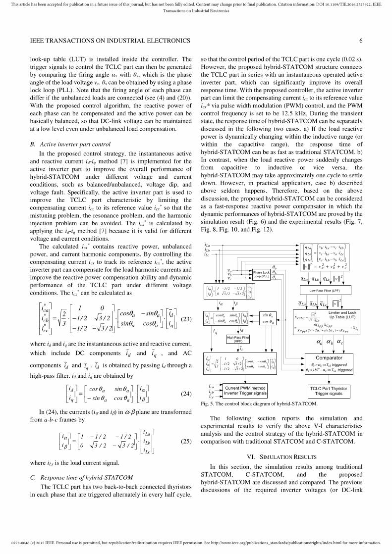
diagram of hybrid-STATCOM is shown in Fig. 5.
A. TCLC part control
Different with the traditional SVC control based on the
traditional definition of reactive power [2]-[3], to improve its
response time, the TCLC part control is based on the
instantaneous pq theory [4]. The TCLC part is mainly used to
compensate the reactive current with the controllable TCLC
part impedance XTCLC. Referring to (3), to obtain the minimum
inverter voltage 0Vinvx≈ , XTCLC can be calculated with Ohm’s
law in terms of the RMS values of the load voltage (Vx) and the
load reactive current (ILqx). However, to calculate the XTCLC in
real time, the expression of XTCLC can be rewritten in terms of
instantaneous values as
Lx
2
Lqx
xTCLC
q3
v
I
VX
⋅== (20)
where v is the norm of the three-phase instantaneous load
voltage and Lxq is the DC component of the phase reactive
power. The real-time expression of v and Lxq can be
obtained by (21) and (22) with low-pass filters.
2c
2b
2a vvvv ++= (21)
⋅−⋅
⋅−⋅
⋅−⋅
=
LabLba
LcaLac
LbcLcb
Lc
Lb
La
iviv
iviv
iviv
q
q
q
(22)
In (21) and (22), vx and qLx are the instantaneous load
voltage and the load reactive power, respectively. As shown in
Fig. 5, a limiter is applied to limit the calculated XTCLC in (9)
within the range of XTCLC>Xind(min) and XTCLC<XCap(min)
(XCap(min)<0). With the calculated XTCLC, the firing angle αx can
be determined by solving (4). Because (4) is complicated, a
0278-0046 (c) 2015 IEEE. Personal use is permitted, but republication/redistribution requires IEEE permission. See http://www.ieee.org/publications_standards/publications/rights/index.html for more information.
This article has been accepted for publication in a future issue of this journal, but has not been fully edited. Content may change prior to final publication. Citation information: DOI 10.1109/TIE.2016.2523922, IEEETransactions on Industrial Electronics
IEEE TRANSACTIONS ON INDUSTRIAL ELECTRONICS 6
look-up table (LUT) is installed inside the controller. The
trigger signals to control the TCLC part can then be generated
by comparing the firing angle αx with θx, which is the phase
angle of the load voltage vx. θx can be obtained by using a phase
lock loop (PLL). Note that the firing angle of each phase can
differ if the unbalanced loads are connected (see (4) and (20)).
With the proposed control algorithm, the reactive power of
each phase can be compensated and the active power can be
basically balanced, so that DC-link voltage can be maintained
at a low level even under unbalanced load compensation.
B. Active inverter part control
In the proposed control strategy, the instantaneous active
and reactive current id-iq method [7] is implemented for the
active inverter part to improve the overall performance of
hybrid-STATCOM under different voltage and current
conditions, such as balanced/unbalanced, voltage dip, and
voltage fault. Specifically, the active inverter part is used to
improve the TCLC part characteristic by limiting the
compensating current icx to its reference value icx* so that the
mistuning problem, the resonance problem, and the harmonic
injection problem can be avoided. The icx* is calculated by
applying the id-iq method [7] because it is valid for different
voltage and current conditions.
The calculated icx* contains reactive power, unbalanced
power, and current harmonic components. By controlling the
compensating current icx to track its reference icx*, the active
inverter part can compensate for the load harmonic currents and
improve the reactive power compensation ability and dynamic
performance of the TCLC part under different voltage
conditions. The icx* can be calculated as
⋅
−⋅
−−
−⋅=
q
d
aa
aa
*cc
*cb
*ca
i
i~
cossin
sincos
2/32/1
2/32/1
01
3
2
i
i
i
θθ
θθ (23)
where id and iq are the instantaneous active and reactive current,
which include DC components di and qi , and AC
components
di~
and qi
~ . di~
is obtained by passing id through a
high-pass filter. id and iq are obtained by
⋅
−=
β
α
θθ
θθ
i
i
cossin
sincos
i
i
aa
aa
q
d (24)
In (24), the currents (iα and iβ) in α-β plane are transformed
from a-b-c frames by
⋅
−
−−=
Lc
Lb
La
i
i
i
2/32/30
2/12/11
i
i
β
α (25)
where iLx is the load current signal.
C. Response time of hybrid-STATCOM
The TCLC part has two back-to-back connected thyristors
in each phase that are triggered alternately in every half cycle,
so that the control period of the TCLC part is one cycle (0.02 s).
However, the proposed hybrid-STATCOM structure connects
the TCLC part in series with an instantaneous operated active
inverter part, which can significantly improve its overall
response time. With the proposed controller, the active inverter
part can limit the compensating current icx to its reference value
icx* via pulse width modulation (PWM) control, and the PWM
control frequency is set to be 12.5 kHz. During the transient
state, the response time of hybrid-STATCOM can be separately
discussed in the following two cases. a) If the load reactive
power is dynamically changing within the inductive range (or
within the capacitive range), the response time of
hybrid-STATCOM can be as fast as traditional STATCOM. b)
In contrast, when the load reactive power suddenly changes
from capacitive to inductive or vice versa, the
hybrid-STATCOM may take approximately one cycle to settle
down. However, in practical application, case b) described
above seldom happens. Therefore, based on the above
discussion, the proposed hybrid-STATCOM can be considered
as a fast-response reactive power compensator in which the
dynamic performances of hybrid-STATCOM are proved by the
simulation result (Fig. 6) and the experimental results (Fig. 7,
Fig. 8, Fig. 10, and Fig. 12).
High Pass Filter
(HPF)
Current PWM method
Inverter Trigger signals
cPFPF
PFPFL
LxxC
CL
Lx
2
TCLC
XX)2sin22(X
XX
q3
vX
+−+−
=
⋅=
πααπ
π
Low Pass Filter (LPF)
Limiter and Look
Up Table (LUT)
aα bα cα
TCLC Part Thyristor
Trigger signals
aθ
bθ
cθPhase Lock
Loop (PLL)
a
a
cos
sin
θ
θ
Laq Lbq Lcq
Laq Lbq Lcq
⋅−⋅
⋅−⋅
⋅−⋅
=
LabLba
LcaLac
LbcLcb
Lc
Lb
La
iviv
iviv
iviv
q
q
q
2c
2b
2a
2vvvv ++=
2v
2v
⋅
−⋅
−−
−⋅=
q
d
aa
aa
*cc
*cb
*ca
i
i~
cossin
sincos
2/32/1
2/32/1
01
3
2
i
i
i
θθ
θθ
⋅
−=
β
α
θθ
θθ
i
i
cossin
sincos
i
i
aa
aa
q
d
⋅
−
−−=
Lc
Lb
La
i
i
i
2/32/30
2/12/11
i
i
β
α
iLaiLbiLc
vavbvc
1xxx T⇒>αθ
2xxo
x T180 ⇒−< αθ
Comparator
triggered
triggered
icaicbicc
di~
qi di
αi βi
Fig. 5. The control block diagram of hybrid-STATCOM.
The following section reports the simulation and
experimental results to verify the above V-I characteristics
analysis and the control strategy of the hybrid-STATCOM in
comparison with traditional STATCOM and C-STATCOM.
VI. SIMULATION RESULTS
In this section, the simulation results among traditional
STATCOM, C-STATCOM, and the proposed
hybrid-STATCOM are discussed and compared. The previous
discussions of the required inverter voltages (or DC-link
0278-0046 (c) 2015 IEEE. Personal use is permitted, but republication/redistribution requires IEEE permission. See http://www.ieee.org/publications_standards/publications/rights/index.html for more information.
This article has been accepted for publication in a future issue of this journal, but has not been fully edited. Content may change prior to final publication. Citation information: DOI 10.1109/TIE.2016.2523922, IEEETransactions on Industrial Electronics
IEEE TRANSACTIONS ON INDUSTRIAL ELECTRONICS 7
voltage invxdc V32V ⋅⋅= ) for these three STATCOMs are
also verified by simulations. The STATCOMs are simulated
with the same voltage level as in the experimental results in
Section VI. The simulation studies are carried out with
PSCAD/EMTDC. Table IV in the Appendix A shows the
simulation system parameters for traditional STATCOM,
C-STATCOM, and hybrid-STATCOM. In addition, three
different cases of loading are built for testing: A. inductive and
light loading, B. inductive and heavy loading, and C. capacitive
loading. These three testing cases are also represented by points
A, B, and C in Fig. 2. The detailed simulation results are
summarized in Table II. Finally, the dynamic response of
hybrid-STATCOM is simulated and discussed in this section
part D. With the consideration of IEEE standard 519-2014 [24],
total demand distortion (TDD) =15% and ISC/IL in 100<1000
scale at a typical case, the nominal rate current is assumed to be
equal to the fundamental load current in the worst-case analysis,
which results in THD=TDD=15%. Therefore, this paper
evaluates the compensation performance by setting THD<15%.
A. Inductive and light loading
When the loading is inductive and light, traditional
STATCOM requires a high DC-link voltage (Vdc> LLV2 −⋅
=269V, Vdc=300V) for compensation. After compensation, the source current isx is reduced to 5.55A from 6.50A and the source-side displacement power factor (DPF) becomes unity from 0.83. In addition, the source current total harmonics distortion (THDisx) is 7.22% after compensation, which satisfies the international standard [24] (THDisx<15%).
For C-STATCOM, the coupling impedance contributes a large voltage drop between the load voltage and the inverter voltage so that the required DC-link voltage can be small (Vdc=80V). The isx, DPF and THDisx are compensated to 5.48A, unity, and 2.01%, respectively.
For the proposed hybrid-STATCOM, the isx, DPF, and THDisx are compensated to 5.48A, unity, and 1.98%, respectively. As discussed in the previous section, a low DC-link voltage (Vdc=50V) of hybrid-STATCOM is used to avoid mistuning of firing angles, prevent resonance problems, and reduce the injected harmonic currents.
B. Inductive and heavy loading
To compensate for the inductive and heavy loading, traditional STATCOM still requires a high DC-link voltage of Vdc=300V for compensation. Traditional STATCOM can obtain acceptable results (DPF = 1.00 and THDisx = 6.55%). The isx is reduced to 5.95A from 8.40A after compensation.
With a low DC-link voltage (Vdc=50V), C-STATCOM cannot provide satisfactory compensation results (DPF = 0.85 and THDisx = 17.5%). However, when the DC-link voltage is increased to Vdc=300V, the compensation results (DPF = 1.00 and THDisx= 7.02%) are acceptable and satisfy the international standard [24] (THDisx<15%). The isx is reduced to 5.90A from 8.40A after compensation.
On the other hand, the proposed hybrid-STATCOM can still obtain acceptable compensation results (DPF = 1.00 and
THDisx = 3.01%) with a low DC-link voltage of Vdc=50V. The isx is reduced to 5.89A from 8.40A after compensation.
C. Capacitive loading
When the loading is capacitive, with Vdc=250V (Vdc<
V269V2 LL =⋅ − ), the compensation results of traditional
STATCOM are acceptable, in which the DPF and THDisx are
compensated to unity and 7.61%. The isx is also reduced to
3.67A from 4.34A after compensation.
For C-STATCOM with Vdc= 50V, the isx increases to 7.10A
from the original 4.34A. The compensation performances
(DPF=0.57 and THDisx=23.5%) are not satisfactory, which
cannot satisfy the international standard [24] (THDisx<15%).
When Vdc is increased to 500V, the DPF is improved to 0.99
and the THDisx is reduced to 10.6%, which can be explained by
its V-I characteristic. However, the compensated isx=5.02A is
still larger than isx=3.73A before compensation.
With the lowest DC-link voltage (Vdc=50V) of the three
STATCOMs, hybrid-STATCOM can still obtain the best
compensation results with DPF=1.00 and THDisx= 3.01%. In
addition, the isx is reduced to 3.41A from 4.34A after
compensation.
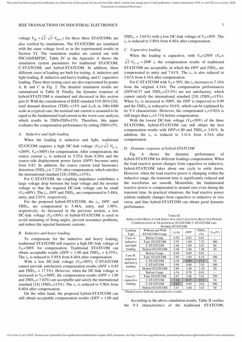
D. Dynamic response of hybrid-STATCOM
Fig. 6 shows the dynamic performance of
hybrid-STATCOM for different loadings compensation. When
the load reactive power changes from capacitive to inductive,
hybrid-STATCOM takes about one cycle to settle down.
However, when the load reactive power is changing within the
inductive range, the transient time is significantly reduced and
the waveforms are smooth. Meanwhile, the fundamental
reactive power is compensated to around zero even during the
transient time. In practical situations, the load reactive power
seldom suddenly changes from capacitive to inductive or vice
versa, and thus hybrid-STATCOM can obtain good dynamic
performance.
TABLE II SIMULATION RESULTS FOR INDUCTIVE AND CAPACITIVE REACTIVE POWER
COMPENSATION OF TRADITIONAL STATCOM, C-STATCOM AND
HYBRID-STATCOM
Loading Type
Without and With STATCOM Comp.
isx(A) DPF THDisx (%) VDC(V)
Case A: inductive and light loading
Before Comp. 6.50 0.83 0.01 --
Trad. STATCOM 5.55 1.00 7.22 300
C-STATCOM 5.48 1.00 2.01 80
Hybrid STATCOM 5.48 1.00 1.98 50
Case B: inductive and heavy
loading
Before Comp. 8.40 0.69 0.01 --
Trad. STATCOM 5.95 1.00 6.55 300
C-STATCOM 6.30 0.85 17.5 50
C-STATCOM 5.90 0.98 7.02 300
Hybrid STATCOM 5.89 1.00 2.10 50
Case C: capacitive
loading
Before Comp. 4.34 0.78 0.01 --
Trad. STATCOM 3.67 1.00 7.61 250
C-STATCOM 7.10 0.57 23.5 50
C-STATCOM 5.02 0.99 10.6 500
Hybrid STATCOM 3.41 1.00 3.01 50
*Shaded areas indicate unsatisfactory results.
According to the above simulation results, Table II verifies
the V-I characteristics of the traditional STATCOM,
0278-0046 (c) 2015 IEEE. Personal use is permitted, but republication/redistribution requires IEEE permission. See http://www.ieee.org/publications_standards/publications/rights/index.html for more information.
This article has been accepted for publication in a future issue of this journal, but has not been fully edited. Content may change prior to final publication. Citation information: DOI 10.1109/TIE.2016.2523922, IEEETransactions on Industrial Electronics
IEEE TRANSACTIONS ON INDUSTRIAL ELECTRONICS 8
C-STATCOM, and hybrid-STATCOM, as shown in Fig. 2.
With similar compensation performance, the capacity of the
active inverter part (or DC-link voltage) of the proposed
hybrid-STATCOM is only about 16% of that of traditional
STATCOM under wide range compensation (both inductive
and capacitive). According to the cost study in [14] and [17],
the average cost of traditional STATCOM is around USD
$60/kVA, whereas that of SVC is only approximately $23/kVA.
Therefore, by rough calculation, the average cost of the
proposed hybrid-STATCOM is just about $33/kVA
(=$60/kVA*16% +$23/kVA), which is 55% of the average cost
of traditional STATCOM. Moreover, because the proposed
hybrid-STATCOM can avoid the use of multilevel structures in
medium-voltage level transmission system in comparison to
traditional STATCOM, the system reliability can be highly
increased and the system control complexity and operational
costs can be greatly reduced.
0.950 0.975 1.000 1.025 1.050 1.075 1.100 1.125 1.150
-200
-100
0
100
200 Ea_source Eb_source Ec_source
-15.0
-7.5
0.0
7.5
15.0 Ia_source Ib_source Ic_source
-400
0
400
800 Q_load_a Q_source_a
Fig. 6. Dynamic compensation waveforms of load voltage, source current, and load and source reactive powers by applying hybrid-STATCOM under different loadings cases.
Based on the above simulation results, a summary can be
drawn as follows:
The traditional STATCOM can compensate for both
inductive and capacitive reactive currents with a high
DC-link operating voltage due to a small coupling inductor.
Due to its high DC-link voltage, the traditional STATCOM
obtains the poor source current THDisx (caused by switching
noise) compared with hybrid-STATCOM.
C-STATCOM has a low DC-link voltage characteristic
only under a narrow inductive loading range. However,
when the loading current is outside its designed range, the
C-STATCOM requires a very high DC-link operating
voltage due to a large coupling capacitor.
The hybrid-STATCOM obtains the best performances of
the three STATCOMs under both inductive and capacitive
loadings.
The hybrid-STATCOM has a wide compensation range
with low DC-link voltage characteristic and good dynamic
performance.
VII. EXPERIMENTAL RESULTS
The objective of the experiment results is to verify that the
proposed hybrid-STATCOM has the characteristics of a wide
compensation range and low DC-link voltage under different
voltage and current conditions, such as unbalanced current,
voltage dip, and voltage fault. The detailed settings of a 110-V,
5-kVA hybrid-STATCOM experimental system are provided
in the Appendix A, and its DC-link voltage is maintained at
VDC=50V for all experiments.
Figs. 7 and 8 show the dynamic compensation waveforms of
load voltage vx, source current isx, and reactive power Qsa of
phase a by applying hybrid-STATCOM for inductive load and
capacitive load compensation. Fig. 9 gives the corresponding
source current harmonic spectrums for inductive and capacitive
reactive power compensations.
(a)
(b)
(c)
Fig. 7 Dynamic compensation waveforms of vx and isx by applying hybrid-STATCOM under (a) inductive load, (b) capacitive load and (c) changing from capacitive load to inductive load.

0278-0046 (c) 2015 IEEE. Personal use is permitted, but republication/redistribution requires IEEE permission. See http://www.ieee.org/publications_standards/publications/rights/index.html for more information.
This article has been accepted for publication in a future issue of this journal, but has not been fully edited. Content may change prior to final publication. Citation information: DOI 10.1109/TIE.2016.2523922, IEEETransactions on Industrial Electronics
IEEE TRANSACTIONS ON INDUSTRIAL ELECTRONICS 9
Fig. 7 clearly shows that after hybrid-STATCOM
compensation, the source current isx and the load voltage vx are
in phase with each other. The source displacement power
factors (DPFs) are compensated to 1.00 from the original 0.69
(for inductive loading) and 0.64 (for capacitive loading). The
worst phase source current THDisx are 3.5% and 5.4% after
compensation, which satisfy the international standard [24]
(THDisx<15%). The source currents isx are also significantly
reduced after compensation. In Figs. 7 (a) and (b), the
hybrid-STATCOM obtains a good dynamic compensation
performance. In Fig. 7(c), the response time is longer than
expected by one cycle because the inductive loads and
capacitive loads are manually switching on and off.
Figs. 10 and 12 illustrate dynamic compensation waveforms
of load voltage vx and source current isx by applying
hybrid-STATCOM under unbalanced loads and voltage fault
situations, which clearly verify its good dynamic performance.
Figs. 11 and 13 give their corresponding source current
harmonic spectrums.
Figs. 10-11 show that the proposed hybrid-STATCOM can
compensate for and balance the source current even under
unbalanced loads with low VDC=50V. The unbalanced isx are
compensated from 4.80A, 3.83A, and 5.74A to 2.94A, 2.79A,
and 2.86A, respectively. The DPF and THDisx are compensated
to unity and lower than 9.0%, which satisfy the international
standard [24]. From Figs. 12-13, it can be seen that the
proposed hybrid-STATCOM can still obtain satisfactory
performances even under asymmetric grid fault. During the
voltage fault, the isx can be compensated to be approximately
balanced with DPF≈1 and THDisx<10.0%.
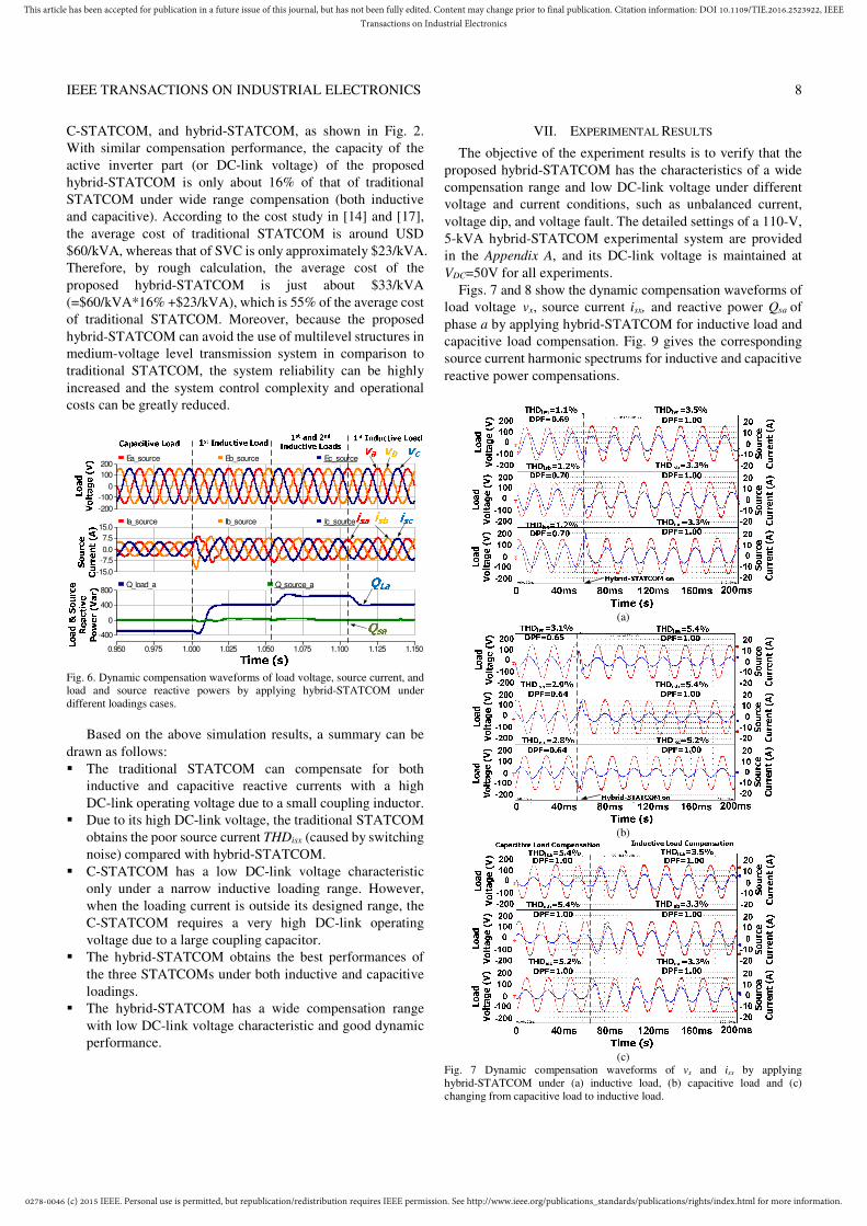
Fig. 14 also provides the dynamic compensation waveforms
of load voltage vx and source current isx by applying
hybrid-STATCOM during a sudden voltage dip. It is found that
hybrid-STATCOM can obtain good dynamic and reactive
power compensation performances.
Fig. 8. Dynamic reactive power compensation of phase a by applying
hybrid-STATCOM.
(a)
(b)
(c)
(d)
Fig. 9. Source current harmonic spectrums of phase a: (a) before compensation of inductive load, (b) after compensation of inductive load, (c) before compensation of capacitive load, and (d) after compensation of capacitive load.
Fig. 10. Dynamic compensation waveforms of vx and isx by applying hybrid-STATCOM under unbalanced loads.
(a)
(d)
(b)
(e)
(c)
(f)
Fig. 11. Source current harmonic spectrums under unbalanced loads before compensation: (a) phase a, (b) phase b, (c) phase c, and after hybrid-STATCOM compensation: (d) phase a, (e) phase b, (f) phase c.
0278-0046 (c) 2015 IEEE. Personal use is permitted, but republication/redistribution requires IEEE permission. See http://www.ieee.org/publications_standards/publications/rights/index.html for more information.
This article has been accepted for publication in a future issue of this journal, but has not been fully edited. Content may change prior to final publication. Citation information: DOI 10.1109/TIE.2016.2523922, IEEETransactions on Industrial Electronics
IEEE TRANSACTIONS ON INDUSTRIAL ELECTRONICS 10
Table III summarizes the hybrid-STATCOM experimental
results. The above experimental results confirm that the
hybrid-STATCOM has a wide reactive power compensation
range and low DC-link voltage characteristics with good
dynamic performance even under different voltage and current
conditions.
Fig. 12. Dynamic compensation waveforms of vx and isx by applying hybrid-STATCOM under voltage fault condition.
(a)
(d)
(b)
(e)
(c)
(f)
Fig. 13. Source current harmonic spectrum under voltage fault before compensation: (a) phase a, (b) phase b. (c) phase c, and after hybrid-STATCOM compensation: (d) phase a, (e) phase b, (f) phase c.
Fig. 14. Dynamic compensation waveforms of vx and isx by applying hybrid-STATCOM during voltage dip.
TABLE III EXPERIMENTAL COMPENSATION RESULTS BY HYBRID-STATCOM (VDC= 50V)
UNDER DIFFERENT SYSTEM AND LOADING SITUATIONS
Different Situations
Comp. isx(A) DPF THDisx (%)
A B C A B C A B C Inductive
load
Before 7.13 7.14 7.34 0.69 0.70 0.70 1.1 1.2 1.2
After 4.79 4.97 4.95 1.00 1.00 1.00 3.5 3.3 3.3
Capacitive load
Before 3.60 3.63 3.65 0.65 0.64 0.64 3.1 2.9 2.8
After 2.92 2.80 2.85 1.00 1.00 1.00 5.4 5.4 5.2
Unbalanced loads
Before 4.80 3.83 5.74 0.36 0.69 0.64 2.0 1.4 1.2
After 2.94 2.79 2.86 1.00 1.00 1.00 5.9 8.7 8.1
Voltage fault
Before 5.57 4.18 7.06 0.67 0.38 0.87 2.3 2.5 1.6
After 4.30 3.98 4.00 0.99 1.00 0.99 4.7 9.3 6.2
VIII. CONCLUSIONS
In this paper, a hybrid-STATCOM in three-phase power
system is proposed and discussed as a cost-effective reactive
power compensator for medium voltage level application. The
system configuration and V-I characteristic of the
hybrid-STATCOM are analyzed, discussed, and compared with
traditional STATCOM and C-STATCOM. In addition, its
parameter design method is proposed on the basis of
consideration of the reactive power compensation range and
prevention of a potential resonance problem. Moreover, the
control strategy of the hybrid-STATCOM is developed under
different voltage and current conditions. Finally, the wide
compensation range and low DC-link voltage characteristics
with good dynamic performance of the hybrid-STATCOM are
proved by both simulation and experimental results.
APPENDIX
A. Settings of simulations and experiments
Table IV shows the simulation system parameters for
traditional STATCOM, C-STATCOM, and hybrid-
STATCOM under different testing loads. For experimental
purposes, a 110-V, 5-kVA experimental prototype of the
three-phase hybrid-STATCOM is constructed in the laboratory.
The control system has a sampling frequency of 25 kHz. The
switching devices for the active inverter are Mitsubishi IGBTs
PM300DSA060. The switching devices for the TCLC are
thyristors SanRex PK110FG160. Moreover, the experimental
parameters of the hybrid-STATCOM are the same as those for
the simulation listed in Table IV.

0278-0046 (c) 2015 IEEE. Personal use is permitted, but republication/redistribution requires IEEE permission. See http://www.ieee.org/publications_standards/publications/rights/index.html for more information.
This article has been accepted for publication in a future issue of this journal, but has not been fully edited. Content may change prior to final publication. Citation information: DOI 10.1109/TIE.2016.2523922, IEEETransactions on Industrial Electronics
IEEE TRANSACTIONS ON INDUSTRIAL ELECTRONICS 11
TABLE IV SIMULATION AND EXPERIMENTAL PARAMETERS FOR TRADITIONAL
STATCOM, C-STATCOM AND HYBRID-STATCOM
Parameters Physical values
System parameters vx, f, Ls 110V, 50Hz,0.1mH
Traditional STATCOM L 5mH
C-STATCOM L, C 5mH, 80uF
Hybrid-STATCOM Lc, LPF, CPF 5mH, 30mH,160uF
Case A. Inductive and light loading LL1, RL1 30mH, 14Ω
Case B. Inductive and heavy loading
LL2, RL2 30mH, 9Ω
Case C. Capacitive loading CL3, RL3 200uF, 20Ω
REFERENCES [1] J. Dixon, L. Moran, J. Rodriguez, and R. Domke, “Reactive power compensation technologies: State-of-the-art review,” Proc. IEEE, vol. 93, no. 12, pp. 2144–2164, Dec. 2005. [2] L. Gyugyi, R. A. Otto, and T. H. Putman, “Principles and applications of static thyristor-controlled shunt compensators,” IEEE Trans. Power App. Syst., vol. PAS-97, no. 5, pp. 1935–1945, Sep./Oct. 1978. [3] T. J. Dionise, “Assessing the performance of a static var compensator for an electric arc furnace,” IEEE Trans. Ind. Appl., vol. 50, no. 3, pp. 1619–1629, Jun. 2014.a [4] F. Z. Peng and J. S. Lai, “Generalized instantaneous reactive power theory for three-phase power systems,” IEEE Trans. Instrum. Meas., vol. 45, no. 1, pp. 293–297, Feb. 1996. [5] L. K. Haw, M. S. Dahidah, and H. A. F. Almurib, “A new reactive current reference algorithm for the STATCOM system based on cascaded multilevel inverters,” IEEE Trans. Power Electron., vol. 30, no. 7, pp. 3577–3588, Jul. 2015. [6] J. A. Munoz, J. R. Espinoza, C. R. Baier, L. A. Moran, J. I. Guzman, and V. M. Cardenas, “Decoupled and modular harmonic compensation for multilevel STATCOMs,” IEEE Trans. Ind. Electron., vol. 61, no. 6, pp. 2743–2753, Jun. 2014. [7] V. Soares and P. Verdelho, “An instantaneous active and reactive current component method for active filters,” IEEE Trans. Power Electron., vol. 15, no. 4, pp. 660–669, Jul. 2000. [8] M. Hagiwara, R. Maeda, and H. Akagi, “Negative-sequence reactive-power control by a PWM STATCOM based on a modular multilevel cascade converter (MMCC-SDBC),” IEEE Trans. Ind. Appl., vol. 48, no. 2, pp. 720–729, 2012. [9] B. Singh and S. R. Arya, “Back-propagation control algorithm for power quality improvement using DSTATCOM,” IEEE Trans. Ind. Electron., vol. 61, no. 3, pp. 1204–1212, Mar. 2014. [10] M.-C. Wong, C.-S. Lam, and N.-Y. Dai, “Capacitive-coupling STATCOM and its control,” Chinese Patent for Invention, Granted, No. 200710196710.6, May 2011. [11] C.-S. Lam, M.-C. Wong, W.-H. Choi, X.-X. Cui, H.-M. Mei, and J.-Z. Liu, “Design and performance of an adaptive low-dc-voltage-controlled LC-Hybrid active power filter with a neutral inductor in three-phase four-wire power systems,” IEEE Trans. Ind. Electron., vol. 61, no. 6 pp. 2635–2647, Jun. 2014. [12] S. Rahmani, A. Hamadi, N. Mendalek, and K. Al-Haddad, “A new control technique for three-phase shunt hybrid power filter,” IEEE Trans. Ind.
Electron., vol. 56, no. 8, pp. 2904–2915, Aug. 2009. [13] S. Rahmani, A. Hamadi, and K. Al-Haddad, “A Lyapunov-function-based control for a three-phase shunt hybrid active filter,” IEEE Trans. Ind. Electron.,
vol. 59, no. 3, pp. 1418–1429, Mar. 2012. [14] H. Akagi and K. Isozaki, “A hybrid active filter for a three-phase 12-pulse diode rectifier used as the front end of a medium-voltage motor drive,” IEEE
Trans. Power Electron., vol. 27, no. 1, pp. 69–77, Jan. 2012. [15] C. Kumar and M. Mishra, “An improved hybrid DSATCOM topology to compensate reactive and nonlinear loads,” IEEE Trans. Ind. Electron., vol. 61, no. 12, pp. 6517–6527, Dec. 2014. [16] J. He, Y. W. Li, and F. Blaabjerg, “Flexible microgrid power quality enhancement using adaptive hybrid voltage and current controller,” IEEE
Trans. Ind. Electron, vol. 61, no. 6, pp. 2784–2794, Jun. 2014. [17] S. Hu, Z. Zhang, Y. Chen, et al. “A new integrated hybrid power quality control system for electrical railway,” IEEE Trans. Ind. Electron., vol. 62, no. 10, pp. 6222 - 6232, Oct. 2015. [18] K-W. Lao, M-C. Wong, N. Y. Dai, C-K. Wong, and C-S. Lam, “A systematic approach to hybrid railway power conditioner design with harmonic compensation,” IEEE Trans. Ind. Electron., vol. 62, no. 2, pp. 930–942, Feb. 2015.
[19] K.-W. Lao, N. Dai, W.-G. Liu, and M.-C. Wong, “Hybrid power quality compensator with minimum DC operation voltage design for high-speed traction power systems,” IEEE Trans. Power Electron., vol. 28, no. 4, pp. 2024–2036, Apr. 2013. [20] A. Varschavsky, J. Dixon, M. Rotella, and L. Moran, “Cascaded nine-level inverter for hybrid-series active power filter, using industrial controller,” IEEE
Trans. Ind. Electron., vol. 57, no. 8, pp. 2761–2767, Aug. 2010. [21] S. P. Litran and P. Salmeron, “Reference voltage optimization of a hybrid filter for nonlinear load reference,” IEEE Trans. Ind. Electron., vol. 61, no. 6, pp. 2648–2654, Jun. 2014. [22] J. Dixon, Y. del Valle, M. Orchard, M. Ortuzar, L. Moran, and C. Maffrand, “A full compensating system for general loads, based on a combination of thyristor binary compensator, and a PWM-IGBT active power filter,” IEEE
Trans. Ind. Electron., vol. 50, no. 5, pp. 982–989, Oct. 2003. [23] W. Y. Dong, “Research on control of comprehensive compensation for traction substations based on the STATCOM technology,” Ph.D. dissertation, Tsinghua Univ., Beijing, China, 2009. [24] IEEE recommended practices and requirements for harmonic control in electrical power systems, 2014, IEEE Standard 519–2014.
Lei Wang received the B.Sc. degree in Electrical and Electronics Engineering from University of Macau (UM), Macao SAR, P. R. China, in 2011 and M.Sc. degree in Electronics Engineering from Hong Kong University of Science and Technology (HKUST), Hong Kong SAR, P. R. China, in 2012.
Since 2012, he joined the Power Electronics Laboratory of University of Macau as a Ph.D student in Electrical and Computer Engineering. His research interests included power electronics, power quality and distribution flexible AC transmission
system (DFACTS), power quality compensation, and renewable energy. Mr. Wang received the champion award in the “Schneider Electric Energy
Efficiency Cup”, Hong Kong, 2011.
Chi-Seng Lam (S’04–M’12) received the B.Sc., M.Sc. and Ph.D. degrees in electrical and electronics engineering from the University of Macau (UM), Macao, China, in 2003, 2006 and 2012 respectively.
From 2006 to 2009, he was an E&M Engineer at UM. From 2009 to 2012, he simultaneously worked as a Laboratory Technician and studied his Ph.D. degree at UM. In 2013, he was a Postdoctoral Fellow in The Hong Kong Polytechnic University. He is currently an
Assistant Professor in the State-Key Laboratory of Analog and Mixed-Signal VLSI, UM. He has co-authored one book: Design and Control of Hybrid Active
Power Filters (Springer, 2014) and over 50 technical journals and conference papers. His research interests include integrated controller, power management IC, and power quality compensators.
Dr. Lam received Macao Science and Technology Invention Award (Third-Class) and R&D Award for Ph.D. in 2014 and 2012, RIUPEEEC Merit Paper Award in 2005. He is Secretary of IEEE Macau Section and PES/PELS Joint Chapter.
Man-Chung Wong (SM’06) received B. Sc. And M. Sc. Degrees in Electrical and Electronics Engineering from Department of Electrical and Electronics Engineering, University of Macau, Macao, P. R. China, in 1993 and 1997 respectively, and PH. D. degree from Tsinghua University, Beijing, P. R. China, in 2003. He was a visiting fellow (July 2014 ~ Dec. 2014) in Cambridge University, UK. He is currently an associate professor in Department of Electrical and Computer Engineering, University of Macau.
Dr. Wong published more than 100 journal and conference papers, and received Young Scientist Award from “Instituto Internacional De Macau” in 2000, Young Scholar Award from University of Macau in 2001, second prize of Tsinghua University Excellent Doctor Thesis Award in 2003, third prize awards of Invention Award of Macau Government Science and Development Award in year 2012 and 2014 respectively.