a long term evolution link level simulator · a long term evolution link level simulator ... figure...
TRANSCRIPT
A Long Term Evolution Link Level Simulator
Albert Serra Pagès
Thesis for the degree of European Master of Research on Information and Communication Technologies at the
Universitat Politècnica de CatalunyaFebruary, 2009
Thesis Advisor: Juan José Olmos BonaféProfessor of Department of Signal Theory and CommunicationsUPC
A Long Term Evolution Link Level Simulator
Abstract
3GPP LTE (Long Term Evolution) is the evolution of the UMTS which will make possible to deliver next
generation high quality multimedia services according to the users' expectations. Since the LTE
performance evaluation needs link and system level simulations, a software tool to simulate the LTE
Downlink based on OFDM technology with MIMO antenna processing is presented in this master thesis.
This simulator contains the MIMO algorithms, the spatial channel models and modulation and coding
schemes for LTE. The result of this simulator serves to evaluate the OFDM-MIMO LTE Link Level
performance in different environments and create link level look-up tables to be used as an input for a
future LTE system level simulator.
ii
A Long Term Evolution Link Level Simulator
Table of ContentsChapter 1. Introduction.............................................................................................................................1
1.1.Outline of this Master Thesis.............................................................................................................3
Chapter 2. Overview of the 3GPP LTE Air Interface .............................................................................4
2.1. 3GPP LTE Air Interface basic concepts............................................................................................4
2.2. Key Technologies of the 3GPP LTE Air Interface............................................................................5
2.2.1. OFDM .....................................................................................................................................5
2.2.2. MIMO ....................................................................................................................................8
2.3. LTE Downlink Physical Layer overview........................................................................................10
2.3.1. LTE radio interface protocol architecture...............................................................................10
2.3.1. DL Physical Layer features....................................................................................................12
2.3.2. DL Frame Structure and physical resource elements.............................................................15
Chapter 3. DL Link Level Simulator Overview....................................................................................17
3.1. DL Link Level Simulator description.............................................................................................17
3.1. E-UTRA physical channel modulation ..........................................................................................19
3.2. LTE downlink physical channel processing ...................................................................................20
Chapter 4. E-UTRA DL Link Level Simulator: MIMO-OFDM physical channel.............................23
4.1. MIMO Wideband Mobile Channel Model......................................................................................23
4.2. Narrowband channel model per subcarrier in MIMO-OFDM system.............................................25
4.3. Correlation-based MIMO radio channel stochastic model..............................................................26
4.4. Physical interpretation of full MIMO channel knowledge..............................................................30
4.5. MIMO Techniques..........................................................................................................................32
4.5.1. Open Loop Spatial Multiplexing: ZF and MMSE ..................................................................33
4.5.2. Open Loop Transmit Diversity: SFBC....................................................................................35
Chapter 5. UTRA DL Link Level Simulator: Channel Coding, Rate Matching and HARQ..............37
5.1. Channel Coding and Rate Matching features..................................................................................37
5.1. E-UTRA Turbo Coding...................................................................................................................39
5.2. LTE Rate Matching and HARQ processes for turbo coded transport channels...............................43
iii
A Long Term Evolution Link Level Simulator
Chapter 6. Simulations and results..........................................................................................................45
6.1. Link Level Simulator Parameters...................................................................................................45
6.2. Validation of the SISO and MIMO OFDM multipath channel........................................................47
6.3. Performance of the different LTE Downlink AMC schemes with MIMO assumption....................48
Chapter 7. Conclusions and Future Work .............................................................................................52
Bibliography.............................................................................................................................................53
Appendixes................................................................................................................................................57
Appendix 1.E-UTRA DL Link Level Performance Results...................................................................57
A1.1.E-UTRA DL Link Level Throughput.......................................................................................57
iv

A Long Term Evolution Link Level Simulator
List of FiguresFigure 2.1: Block diagram of an SISO OFDM based transmission system. .................................................7
Figure 2.2: Block diagram of a NRX·MTX MIMO-OFDM based transmission system. ............................9
Figure 2.3: Radio interface protocol architecture around the physical layer..............................................10
Figure 2.4: LTE Downlink Resource Grid..................................................................................................16
Figure 3.1: Interface between link level and system level simulations......................................................17
Figure 3.2: Flow diagram of LTE Link Level simulator............................................................................19
Figure 3.3: LTE downlink signal processing for transmit diversity and spatial multiplexing....................21
Figure 4.1: Two antenna arrays in a scattering environment......................................................................24
Figure 4.2: Scheme of a MIMO-OFDM broadband system.......................................................................25
Figure 4.3: Flow chart of the Kronecker correlated channel coefficient generation (Source [42])............29
Figure 4.4: Equivalence of the MIMO physical model based on SVD channel decomposition.................30
Figure 4.5: Block diagram of the MIMO Spatial Multiplexing with Linear detection................................33
Figure 4.6: Block diagram of the MIMO Trasnmit Diversity: 2x2 SFBC with Alamouti Code and MRC..35
Figure 5.1: E-UTRA DL Link Level Simulator block diagram...................................................................38
Figure 5.2: Structure of rate 1/3 turbo encoder (dotted lines apply for trellis termination only).................40
Figure 5.3: Block diagram of the turbo decoder. ........................................................................................41
Figure 5.4: Trellis of each 8-state constituent encoders.. ...........................................................................42
Figure 5.5: Rate Matching for turbo coded transport channels [8]..............................................................43
Figure 5.6: Circular Buffer Representation ................................................................................................44
Figure 6.1: EPA channel Power Delay Profile...........................................................................................45
Figure 6.2: Uncoded BER validation of DL 2 x 2 Uncorrelated SISO channel .........................................47
Figure 6.3: Uncoded BER validation of DL 2 x 2 Uncorrelated MIMO channel ......................................48
Figure 6.4: Uncoded BER performance results in case of Spatial Multiplexing, ZF Detector and 2 x 2
MIMO .......................................................................................................................................................49
Figure 6.5: Uncoded BER performance results in case of Spatial Multiplexing, MMSE Detector and 2 x 2
MIMO........................................................................................................................................................49
Figure 6.6: Uncoded BER performance results in case of Transmit Diversity, Alamouti/MRC and 2 x 2
MIMO........................................................................................................................................................50
v

A Long Term Evolution Link Level Simulator
Figure 6.7: E-UTRA DL AMC 2x2 MIMO link level throughput of the MCS classes with H-ARQ (8 turbo
decoding iterations. Code block size: 40-120 bits).....................................................................................51
Figure A.1: E-UTRA DL AMC link level throughput with H-ARQ in AWGN SISO channel (8 turbo
decoding iterations. Code block size: 40-120 bits).....................................................................................57
Figure A.2: E-UTRA DL AMC link level throughput with H-ARQ in Rayleigh Fading SISO channel (8
turbo decoding iterations. Code block size: 40-120 bits)............................................................................58
Figure A.3: E-UTRA DL AMC link level throughput with H-ARQ in 2 x 2 Low Correlated MIMO
channel and ZF Detector (8 turbo decoding iterations. Code block size: 40-120 bits)................................58
Figure A.4: E-UTRA DL AMC link level throughput with H-ARQ in 2 x 2 Medium Correlated MIMO
channel and ZF Detector (8 turbo decoding iterations. Code block size: 40-120 bits)................................59
Figure A.5: E-UTRA DL AMC link level throughput with H-ARQ in 2 x 2 High Correlated MIMO
channel and ZF Detector (8 turbo decoding iterations. Code block size: 40-120 bits)................................59
Figure A.6: E-UTRA DL AMC link level throughput with H-ARQ in 2 x 2 Low Correlated MIMO
channel and MMSE Detector (8 turbo decoding iterations. Code block size: 40-120 bits).........................60
Figure A.7: E-UTRA DL AMC link level throughput with H-ARQ in 2 x 2 Medium Correlated MIMO
channel and MMSE Detector (8 turbo decoding iterations. Code block size: 40-120 bits).........................60
Figure A.8: E-UTRA DL AMC link level throughput with H-ARQ in 2 x 2 High Correlated MIMO
channel and MMSE Detector (8 turbo decoding iterations. Code block size: 40-120 bits).........................61
Figure A.9: E-UTRA DL AMC link level throughput with H-ARQ in 2 x 2 Low Correlated MIMO
channel and Transmit Diversity Alamouti/MRC (8 turbo decoding iterations. Code block size: 40-120
bits).............................................................................................................................................................61
Figure A.10: E-UTRA DL AMC link level throughput with H-ARQ in 2 x 2 Medium Correlated MIMO
channel and Transmit Diversity Alamouti/MRC (8 turbo decoding iterations. Code block size: 40-120
bits).............................................................................................................................................................62
Figure A.11: E-UTRA DL AMC link level throughput with H-ARQ in 2 x 2 High Correlated MIMO
channel and Transmit Diversity Alamouti/MRC (8 turbo decoding iterations. Code block size: 40-120
bits).............................................................................................................................................................62
vi

A Long Term Evolution Link Level Simulator
List Of TablesTable 2.1. LTE Bandwidth and Resource Configuration ............................................................................13
Table 2.2. Downlink Peak Rates for E-UTRA............................................................................................15
Table 2.3. Physical resource block parameters...........................................................................................16
Table 4.1. 3GPP LTE definition of the MIMO correlation matrix coefficients...........................................27
Table 4.2. LTE space frequency block code mapping.................................................................................36
Table 6.1.E-UTRA DL link level parameters..............................................................................................46
vii

A Long Term Evolution Link Level Simulator
Notation
Acronyms
3GPP Third Generation Partnership Project
AMC Adaptive Modulation and Coding
ARQ Automatic repeat request/query
BER Bit Error Rate
BLER Block Error Rate
BS Base Station
CP Cyclic Prefix
CSI Channel State Information
DFT Discrete Fourier transform
DL Downlink
EPS Evolved Packet System
E-UTRAN Evolved UTRAN
FFT Fast Fourier transform
FDD Frequency-division duplex
FDM Frequency Division Multiplexing
FDMA Frequency-division multiple access
HARQ Hybrid ARQ
HSDPA High Speed Downlink Packet Access
viii

A Long Term Evolution Link Level Simulator
HSPA High-speed packet access
IDFT Inverse Discrete Fourier Transform
IFFT Inverse Fast Fourier Transform
ISI Inter-Symbol Interference
LTE Long-term evolution
MIMO Multiple Input Multiple Output
PRB Physical Resource Block
OFDM Orthogonal frequency-division multiplexing
OFDMA Orthogonal Frequency Division Multiple Access
QAM Quadrature Amplitude Modulation
QoS Quality of Service
SAE System Architecture Evolution
SC-FDMA Single Carrier Frequency Division Multiple Access
SFBC Space-frequency block coding
SISO Single Input Single Output
SM Spatial Multiplexing
SVD Singular Value Decomposition
TD Transmit Diversity
TDD Time-division duplex
TTI Transmission Time Interval
UE User Equipment
UL Uplink
UTRAN UMTS Terrestrial Radio Access Network
ix
A Long Term Evolution Link Level Simulator
Chapter 1. Introduction
3GPP LTE is the evolution of the Third-generation of mobile communications, UMTS, to the Fourth-
generation technology, that is essentially a wireless broadband Internet system with voice and other
services built on top. The specifications related to LTE are formally known as the evolved UMTS
terrestrial radio access (E-UTRA) and evolved UMTS terrestrial radio access network (E-UTRAN), but
are more commonly referred to by the project name LTE. The starting requirements of LTE are presented
in [1] and [2], where its main targets for this evolution are highlighted. LTE is designed to increase data
rates and cell edge bitrates, improve spectrum efficiency (unicast as well as broadcast) and allow spectrum
flexibility (1.25, 2.5, 5, 10, 15 and 20 MHz) for flexible radio planning. LTE has also to reduce packet
latency, the main restriction for real-time services, such as VoIP or videconferencing, reduce radio access
network cost as well as cost-effective migration from earlier 3GPP releases and simplify its network to a
flat all-IP packet-based network architecture where all the user plane radio functionalities are terminated at
the eNodeB.
3GPP started to work on the Evolution of the UMTS with the RAN Evolution Work Shop in November
2004 and, recently, on December 2008, 3GPP has approved the functional freeze of LTE as part of Release
8. Therefore, this landmark achievement will allow the operators to realize their early deployment plans
in deploying this technology. LTE is aimed at providing the true global mobile broadband experience for
users but also places high priority on improving spectral efficiency and reducing cost. An overview and a
summary of all Release 8 features with its associated 3GPP LTE specification documents is presented in
[3].
LTE should at least support an instantaneous downlink peak data rate of 100Mbps within a 20 MHz
downlink spectrum allocation (5bps/Hz) and instantaneous uplink peak data rate of 50Mbps within a 20
MHz uplink spectrum allocation (2.5bps/Hz) considering 2 receive antennas and 1 transmit antenna at UE.
1
Chapter 1. Introduction
Therefore, the key point of LTE to achieve its peak data rate target is the specification of an extremely
flexible Radio Interface based on OFDM technology with MIMO antenna processing, where all services
are supported on packet based shared transport channels [4]-[5].
The innovations introduced by LTE open important research challenges related with the optimization of
the physical and MAC layers of 3GPP LTE. The work of this master thesis is centered in the study of the
performance and validity of the MIMO-OFDM tandem for the case of a cellular high mobility systems,
such as LTE. But simultaneous simulations of all the processes involved in the operation of a wireless
system is an infeasible and impractical task and the solution is to divide the simulation into link and
system levels. This document takes the part of the study involved in the link level simulation, therefore,
the aim of this master thesis is to present the development of a LTE Link Level Simulator based on LTE
Physical Layer specifications [6]-[9]. This simulator emulates the MIMO algorithms, the OFDM signal,
the spatial channel model, the channel modulation, the coding scheme, the rate matching and the H-ARQ
process on the communication involved in the LTE downlink between the transmitter, the base station
eNodeB, and the receiver, the user equipment UE. This master thesis is focused on the downlink, so the
implementation of LTE uplink is not considered in this document.
The result of the LTE DL link level simulator serves to characterize the LTE wireless link and create link
level look-up tables (LUT) that average the bit error rate (BER), the block error rate (BLER) and the
throughput performance vs. SINR (Signal to Interference-Noise Ratio) averaged over all channel
realizations of one specific channel model in different scenarios. But in many cases, these average LUTs
are not enough to model properly the link layer because the specific channel realization encountered may
perform significantly different from the average performance. Consequently, a next step of the DL link
level simulator will be to add the calculation of the Effective SNIR mapping functions that take account of
the instantaneous channel and interference conditions [12]. These Effective SNIR mapping tables are
constructed on the link level and they represent tabulated BER functions of instantaneous system level
SINR. Finally, a LTE system level simulator will have to be developed to use the results of the DL link
level simulator.
2

A Long Term Evolution Link Level Simulator
1.1. Outline of this Master Thesis
This master thesis is divided into 7 chapters:
➢Firstly, Chapter 1 corresponds to the introduction describing the general LTE background and the
motivation of this master thesis and Chapter 2 presents the background of the 3GPP LTE Air Interface
Technology.
➢Chapter 3 describes the LTE link level simulator framework and gives the guidelines for this kind of
simulators in order to be interfaced to system level simulators. Finally, the inputs and outputs of the LTE
link level simulator are described and a block diagram of the LTE downlink physical channel processing
is presented following the LTE Physical Layer description [7] and [8].
➢Chapter 4 analyses the basics and the multi-antenna techniques to model a MIMO-OFDM Wideband
channel for the LTE DL MIMO-OFDM physical channel simulator, that is the fist stage of the LTE DL
link level simulator.
➢Chapter 5 describes the LTE channel coding and rate matching techniques implemented in the the
second stage of the LTE DL link level simulator.
➢Chapter 6 evaluates the performance results of the MIMO-OFDM link level simulators, and,
furthermore, they are compared to SISO-OFDM link level simulation results.
➢Finally, Chapter 7 summarizes the concluding remarks and lists the functionalities of LTE DL link level
simulator presented in this master thesis and proposes the future work to be done in order to continue the
investigation performed in this master thesis.
3

Chapter 1. Introduction
Chapter 2. Overview of the 3GPP LTE Air Interface
2.1. 3GPP LTE Air Interface basic concepts
The starting point of LTE study item was first focused on the definition of requirements to define the
targets for data rate, capacity, spectrum efficiency and latency. Also commercial aspects like costs for
installing and operating the network were considered. Based on these requirements, the key features of
LTE are the usage of multiple access schemes, adaptive modulation and coding, multi antenna techniques
(MIMO), hybrid automatic repeat request (HARQ) technology and distributed or localized radio resource
allocation techniques. A general overview of LTE is given in [10] and [11] and next paragraphs of this
chapter describes briefly the LTE key technology applied to DL link level simulator.
The multiple access schemes that uses LTE are OFDMA with Cyclic Prefix (CP) in DL and Single Carrier
FDMA (SC-FDMA) with CP in UL. OFDM/OFDMA have been selected by 3GPP because of its
robustness to multipath propagation in wideband channels, inherent support for frequency diversity and
easiness integration with MIMO antenna schemes. Inside each subcarrier Adaptive Modulation and
Coding (AMC) is applied with three modulation schemes (QPSK, 16QAM and 64QAM) and variable
code rates. LTE performs link adaptation via AMC (explicit adaptation) and HARQ (implicit adaptation to
errors) in a fast pace (each 2 slots, or 1 ms) providing data quickly and reliably using minimal resources.
The addition of AMC and HARQ process allows to minimize the turnaround time and maximize the data
throughput of the system.
4
A Long Term Evolution Link Level Simulator
The LTE specifications inherit all the frequency bands defined for UMTS and add more bands and
describe both Frequency Division Duplexing (FDD) and Time Division Duplexing (TDD) to separate
uplink and donwlink traffic. Anyway, this document only considers the downlink FDD case for the DL
link level simulator.
MIMO techniques play an important role in fulfilling the LTE requirements on increased data rates and
improved coverage and capacity. Multiple antennas can be found in the transmitter and/or in the receiver.
Therefore, different multi-antenna transmission techniques can be employed. The main techniques are
Single stream transmit diversity, Beamforming, Spatial Division Multiplexing (SDM), and Spatial
Division Multiple Access (SDMA). Some of the multi-antenna schemes are based on the utilization of
precoding matrices which are defined by LTE specifications and whose selection is implementation
dependant [7].
The work of this master thesis has consisted in developing a LTE DL link level simulator which takes
into account the following LTE physical layer features: the mobile environment; the spatial channel
models, SISO and MIMO radio channels; OFDM DL transmission; the LTE modulation schemes, QPSK,
16QAM and 64QAM; the LTE channel coding with variable code rates and HARQ process.
2.2. Key Technologies of the 3GPP LTE Air Interface
2.2.1. OFDM
OFDM is frequency-division multiplexing scheme utilized as a digital multi-carrier modulation method
that it has been used successfully in wire-line access applications, such as Digital Subscriber Line (DSL)
modems and cable modems. Recently, wireless systems such as 3GPP LTE have also adopted OFDM-
based transmissions to overcome the challenges of Non Line Of Sight (NLOS) propagation because
OFDM is a technology that has been shown to be well suited to the mobile radio environment for high rate
and multimedia services [12].
5

Chapter 2. Overview of the 3GPP LTE Air Interface
OFDM achieves high data rate and efficiency by using multiple overlapping carrier signals instead of just
one carrier. The key advantage of OFDM over single carrier modulation schemes is the ability to
subdivide the bandwidth into multiple frequency sub-carriers which carry the information streams, are
orthogonal to each other and deliver higher bandwidth efficiency. Therefore OFDM allows higher data
throughput even in the face of challenging scenarios such as NLOS links suffering from significant
degradation because of multipath conditions. Therefore, a guard time is added in each OFDM symbol to
combat the channel delay spread. The term delay spread describes the amount of time delay at the receiver
from a signal traveling from the transmitter along different paths. The delay induced by multipath can
cause a symbol received along a delayed path to interfere with subsequent symbol arriving at the receiver
via a more direct path. This effect is referred to as inter-symbol interference (ISI).
The guard time may be divided into a prefix (inserted at the beginning of the useful OFDM symbol and
called cyclic prefix (CP)) and a postfix (inserted at the end of the previous OFDM symbol). The
introduction of the CP can eliminate ISI in the time domain as long as the CP duration is longer than the
channel delay spread. The CP is typically a repetition of the last samples of data portion of the OFDM
block that is appended to the beginning of the data payload and makes the channel appear circular in order
to permit low-complexity frequency domain equalization.
OFDM signal generation consists of multiplexing the original data stream into Nc parallel data streams;
then and each of the data streams is modulated with a different subcarrier frequency using linear
modulation (either PSK or QAM). Then, the resulting signals are transmitted together in the same band.
Correspondingly, the receiver consists of Nc parallel receiver paths because of the Nc equally spaced
orthogonal subcarriers of OFDM symbol behaves as Nc independent narrowband flat fading channels. In
short, OFDM converts the wideband frequency selective fading channel into Nc narrowband flat fading
channels thus the equalization can be performed in the frequency domaing by a scalar division carrier-
wise with the subcarrier related channel coefficients. Therefore, this fact reduces dramatically the
equalization complexity.
The subcarrier pulse used for OFDM transmission is chosen to be rectangular and this has the advantage
6

A Long Term Evolution Link Level Simulator
that the task of pulse forming and modulation can be performed by a simple Inverse Discrete Fourier
Transform (IDFT) at the transmitter. In practice, the IDFT is implemented very efficiently as an Inverse
Fast Fourier Transform (IFFT) and the IFFT keeps the spacing of the subcarriers ortoghonal and not
requires intra-cell interference cancellation. Accordingly at the receiver we only need a FFT to reverse this
operation but the receiver and the transmitter must be perfectly synchronized. Therefore, according to the
theorems of the Fourier Transform, the rectangular pulse shape will lead to a sinc type of spectrum of the
subcarriers that are overlap but the information transmitted can still be separated because of the
orthogonality relation between subcarriers.
Figure 2.1 shows the block diagram of a OFDM based transmission system with only one single antenna
at the transmitter and one at the receiver and how to characterize a multipath radio channel for OFDM
systems is described in [13]. Then, how to create the mobile channel models to be used for 3GPP
deployment evaluation is explicitly described in [14] where simplifications in order to reduce the
computational cost and the complexity of the simulations are presented.
Figure 2.1: Block diagram of an SISO OFDM based transmission system.
7
Channel Coding/
Inter-leaving
Channel
Symbol
Modulation
OFDM
modulation IFFT
Insert Cyclic Prefix
RF
Transmit
Channel Decoding/ De-inter-leaving
Symbol
detection
OFDM demodu-
lation FFT
Remove Cyclic Prefix
RF
Receive

Chapter 2. Overview of the 3GPP LTE Air Interface
2.2.2. MIMO
MIMO, or multiple-input and multiple-output, is a smart antenna technique based on the use of multiple
antennas at both the transmitter and receiver to improve radio link communication performance. MIMO
technology is considered in the new wireless communications standards such as 3GPP LTE or WIMAX
since it offers significant increases in data throughput and link range without additional bandwidth or
transmit power. It achieves this by higher spectral efficiency (more bits per second per hertz of bandwidth)
and link reliability or diversity (reduced fading).
The MIMO technique in combination with OFDM (MIMO-OFDM) has been shown as a approach for
high spectral efficiency wideband systems because OFDM technique simplifies the receiver structure by
decoupling frequency selective MIMO channel into a set of parallel flat fading channels and different data
is sent to different subcarriers. Then the fading process experienced by each subcarrier is close to
frequency flat, and therefore, it can be modeled as a constant complex gain. This consideration allows to
obtain the MIMO channel matrix of transmission coefficients per subcarrier and simplify the
implementation of a MIMO scheme provided this is applied on a each subcarrier. MIMO-OFDM basics
are described in[15-20] describes and Figure 2.2 shows the block diagram of a MIMO-OFDM based
transmission system where NRX and MTX are the number of antennas at the transmitter and at the receiver,
respectively.
MIMO can be split into transmit diversity and spatial multiplexing techniques and it depends on the
channel condition which MIMO technique to select. Transmit diversity increases coverage and quality of
service (QoS) because relies on transmitting multiple redundant copies of a data stream to the receiver;
while spatial multiplexing increases the spectral efficiency because transmits independent and separately
data streams from each of the multiple antennas. Apart from that, MIMO may be used to reduce co-
channel interference and provide an array gain, what is called beamforming.
MIMO systems present two modes of operation, open-loop and closed-loop. While open loop MIMO
8

A Long Term Evolution Link Level Simulator
systems only knows the channel state information (CSI) at the receiver side, closed-loop MIMO systems
also knows the CSI at the transmitter side and it can improve the throughput and reliability of a MIMO
system. The estimation of CSI is based on pilot symbols and UEs can report the channel state information
back to the BS to use for the next transmissions, provided the channel variation because of mobile speed
and environmental changes is slow.
Figure 2.2: Block diagram of a NRX·MTX MIMO-OFDM based transmission system.
Open-loop spatial multiplexing can employ different strategies of detection at the receiver side, basically
divided in linear detectors, such as Zero Forcing (ZF) and minimum mean-square-error (MMSE), or non-
linear, Maximum Likelihood (ML), Successive Interference Cancellation (SIC) or Parallel Interference
Cancellation (PIC).
Examples of open-loop transmit diversity are space-time block coding (STBC) and space-frequency block
coding (SFBC). Here the most known code is the Alamouti code for the case of 2 antennas at transmitter
[51]. The STBC and SFBC techniques consist of sending the data stream from each of the transmit
9
Multip
ath Chan
nel
Channel Encoder & Interleaving
Symbol
Modulation OFDM
modulator 1 IFFT
Single or multi data streams
MIMO
encoder OFDM
modulator 2 IFFT
OFDM modulator MTX IFFT
OFDM demodulator 1
FFT
OFDM demodulator 2
FFT
OFDM demodulator NRX
FFT
MIMO
decoder
MIMO Channel and SNR estimator
Channel Decoder &
DeInterleaving
Symbol
Demodulation
Detected data streams
Channel Quality Information (CQI) feedback
Chapter 2. Overview of the 3GPP LTE Air Interface
antennas using certain principles of full or near orthogonal coding and diversity exploits the independent
fading in the multiple antenna links to enhance signal.
A closed-loop MIMO system has knowledge of the channel at transmitter and it allows to perform a
MIMO precoding at transmitter for channel compensation based on a precoding weight matrix selected
from a set of matrices called “codebook”. In particular, the codebook matrix selection is based on the
channel estimation of the receiver that feedbacks the best precoding matrix to maximize the capacity to
the transmitter.
2.3. LTE Downlink Physical Layer overview
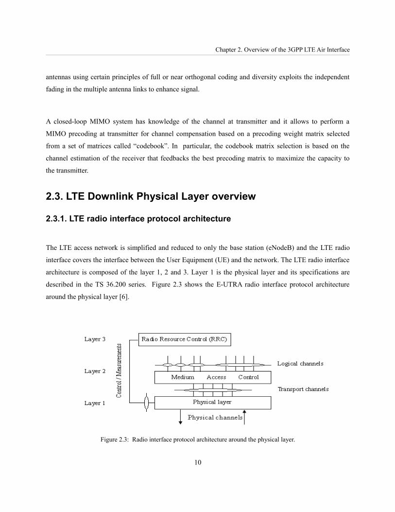
2.3.1. LTE radio interface protocol architecture
The LTE access network is simplified and reduced to only the base station (eNodeB) and the LTE radio
interface covers the interface between the User Equipment (UE) and the network. The LTE radio interface
architecture is composed of the layer 1, 2 and 3. Layer 1 is the physical layer and its specifications are
described in the TS 36.200 series. Figure 2.3 shows the E-UTRA radio interface protocol architecture
around the physical layer [6].
Figure 2.3: Radio interface protocol architecture around the physical layer.
10

A Long Term Evolution Link Level Simulator
The LTE air interface consists of physical channels and physical signals which are defined in [7] and are
generated by the LTE physical layer. Physical channels carry data from higher layers including control,
scheduling and user payload and physical signals are used for system synchronization, cell identification
and radio channel estimation.
The types of downlink physical channels are Physical Downlink Shared Channel (PDSCH), Physical
Broadcast Channel (PBCH), Physical Multicast Channel (PMCH), Physical Control Format Indicator
Channel (PCFICH), Physical Downlink Control Channel (PDCCH) and Physical Hybrid ARQ Indicator
Channel (PHICH). The types of uplink physical channels are PRACH (Physical random access channel),
PUCCH (Physical uplink control channel) and PUSCH (Physical uplink shared channel). Concerning to
physical signals, there are two types of signals, Reference signal and Synchronization signal.
The physical layer interfaces the Medium Access Control (MAC) of Layer 2 and the Radio Resource
Control (RRC) of Layer 3. The physical layer offers a transport channel to MAC and a transport channel
is characterized by how the information is transferred over the radio interface. MAC offers different
logical channels to the Radio Link Control (RLC) of Layer 2 and a logical channel is characterized by the
type of information transferred. Then, the physical layer performs the following functions in order to
enable data transport service:
➢ LTE physical layer functions applied to transport channels : Error detection on the transport
channel and indication to higher layers; FEC encoding/decoding of the transport channel; rate matching
of the coded transport channel to physical channels and mapping of the coded transport channel onto
physical channels.
➢ LTE physical layer Functions applied to physical channels : Power weighting of physical channels
and Modulation and demodulation of physical channels;
➢ Other LTE physical layer Functions : Hybrid ARQ soft-combining; power weighting of physical
channels; frequency and time synchronization; radio characteristics measurements and indication to
higher layers; multiple Input multiple Output (MIMO) antenna processing; transmit diversity (TX
diversity); beamforming and RF processing.
11

Chapter 2. Overview of the 3GPP LTE Air Interface
2.3.1. DL Physical Layer features
The LTE DL physical layer is defined in LTE specifications [6-9] and [21-23]. The LTE physical layer is
based on Single Carrier Frequency-Division Multiple Access (SC-FDMA) for the UL and Orthogonal
Frequency-Division Multiple Access (OFDMA) for the DL. LTE supports both Frequency Division
Duplex (FDD) and Time Division Duplex (TDD) modes and each one has its own frame structure.
OFDMA is a multi-user version of OFDM scheme and is employed as the multiplexing scheme of LTE
DL. Multiple access is achieved by assigning subsets of subcarriers, called sub-channels, to individual
users and this allows simultaneous low data rate transmission from several users (each user is assigned a
specific time-frequency resource). The OFDMA symbol structure consists of three types of sub-carriers,
data sub-carriers for data transmission, pilot sub-carriers for estimation and synchronization purposes and
Null sub-carriers for no transmission; used for guard bands and DC carriers. OFDMA may support
frequency reuse of one, i.e., all cells/sectors operate on the same frequency channel to maximize spectral
efficiency. But in this case, some form of frequency planning at the cell edges is required using a plan for
frequency re-use to avoid inter-cell interference. While in the center of the cell, the entire channel
bandwidths can be used.
The E-UTRA OFDMA data channels are shared channels, i.e., for each transmission time interval (TTI) of
1 ms, a new scheduling decision is taken regarding which users are assigned to which time/frequency
resources during this TTI. The TTI duration of 1 ms contributes to minimize the low user-plane latency in
order to achieve high bit rate for data services.
The LTE physical layer supports different bandwidths from 1.4 MHz to 20 MHz with subcarrier spacing
of 15 kHz. A subcarrier spacing of 7.5 kHz is also possible that is used in the new LTE eMBMS (evolved
multimedia broadcast and multicast service). In both cases, the subcarrier spacing is constant regardless of
the channel bandwidth. The smallest amount of resource that can be allocated in the uplink or downlink is
called a resource block (RB). An RB is 180 kHz wide and lasts for one 0.5 ms timeslot. For standard LTE,
12

A Long Term Evolution Link Level Simulator
an RB comprises 12 subcarriers at a 15 kHz spacing, and for eMBMS with the optional 7.5 kHz subcarrier
spacing an RB comprises 24 subcarriers for 0.5 ms. The maximum number of RBs supported by each
transmission bandwidth is given in Table 2.1 [21]-[22].
Channel bandwidth BWChannel [MHz] 1.4 3 5 10 15 20Number of Resource Blocks (NRB) 6 15 25 50 75 100Number of occupied subcarriers 72 180 300 600 900 1200IFFF/FFT Size 128 256 512 1024 1536 2048Subcarrier Spacing 15kHz / 7.5 kHz
Table 2.1. LTE Bandwidth and Resource Configuration
The modulation schemes supported in the LTE DL and UL over each subcarrier are QPSK, 16QAM and
64QAM. LTE applies Adaptive Modulation and Coding (AMC) and variable coding rates inside each
subcarrier combined to the retransmission protocol H-ARQ (Hybrid Automatic Repeat Request).
Adaptive modulation is a technique that allows to maintain the Bit Error Rate (BER) below a predefined
target value by modifying the signal transmitted to a particular user according to the instantaneous radio
link quality. Coding scheme may be also modified along the time to match the instantaneous channel
conditions for each user. Therefore, when both modulation and coding scheme are jointly changed by the
transmitter to adapt the transmitted signal to the varying channel conditions, this is called AMC (Adaptive
Modulation and Coding) technique.
The channel coding scheme for transport blocks in LTE is Turbo Coding with a coding rate of R=1/3, two
8-state constituent encoders and a contention-free quadratic permutation polynomial (QPP) turbo code
internal interleaver. Trellis termination is used for the turbo coding. Before the turbo coding, transport
blocks are segmented into byte aligned segments with a maximum information block size of 6144 bits.
Error detection is supported by the use of 24 bit CRC.
HARQ is implemented as MAC level (L1) module called HARQ entity. HARQ entity is associated with N
HARQ processes to implement N stop and wait HARQ protocol. HARQ is a stop and wait protocol that
facilitates fast error detection and correction as subsequent transmission can take place only after
13
Chapter 2. Overview of the 3GPP LTE Air Interface
receiving ACK/NACK from the receiving entity. In case an ACK is received a new transmission is done,
else a retransmission is done. Therefore, The HARQ protocol gives the receiver redundancy information
that enables to reduce the BLER and HARQ and AMC are jointly critical techniques to enable to minimize
the turnaround time and maximize the data throughput of the system.
The LTE/E-UTRA physical layer is designed to exploit MIMO wireless transceivers, at both the base
station (BS) and the user equipment (UE), in order to enhance link robustness and increase data rates
compared to SISO channels. In LTE, the use of MIMO is compulsory and the baseline configuration is
2x2, two transmit antennas at the eNodeB and two receive antennas at the UE. Higher-order MIMO
configurations are also taken into account; particularly, the 4x2 and 4x4 MIMO (four antennas at
transmitter and two or four at receiver, respectively) in E-UTRA Release 8 [7]. In the future LTE
Advanced specifications, MIMO antenna configurations could be 8x8 or less for donwlink and 4x4 or less
for uplink [24].
MIMO is integrated as part of E-UTRA physical layer because the requirements on coverage, capacity and
data rates make necessary to incorporate new transmission schemes, such as beamforming, spatial
multiplexing or transmit diversity. Transmit diversity is primarily intended for common downlink
channels as it can be difficult to apply other sources of diversity such as retransmission or link adaptation.
Transmit diversity is based on space-frequency block coding (SFBC) techniques complemented with
frequency-shift time diversity (FSTD) when four transmit antennas are used. Then, spatial multiplexing
enables to send independent streams of data simultaneously on the same DL resource block(s). Data
stream can belong to one single user (single user SU-MIMO) or to different users (multi user MU-
MIMO). SU-MIMO increases the data rate of one user, and, on the other hand, MU-MIMO increases the
overall capacity.
The estimated downlink peak rates deemed feasible with E-UTRA are summarized in Table 2.2 [5] and the
usage of MIMO techniques may achieve and even exceed the peak rate requirements outlined in [1].
14

A Long Term Evolution Link Level Simulator
DownlinkAssumptions 64 QAM, Rate=1; Signal overhead for reference signals and control channel occupying one OFDM symbol.Unit Mbps in 20 MHz b/s/HzRequirement 100 5.02x2 MIMO 172.8 8.64x4 MIMO 326.4 16.3
Table 2.2. Downlink Peak Rates for E-UTRA.
2.3.2. DL Frame Structure and physical resource elements
The E-UTRA frame structures are defined in [21-24]. DL and UL transmissions are organized into radio
frames with 10ms duration. Two radio frame structures are supported: Type 1, applicable to FDD and Type
2, applicable to TDD. Frame structure type 1 (FDD) is applicable to both full duplex and half duplex
FDD. The generic radio frame for FDD and TDD has a duration of 10ms and consists of 20 slots with a
slot duration of 0.5ms. Two consecutive slots form one sub-frame of length 1ms that it is the shortest
Transmit Time Interval (TTI). Each sub-frame or slot consists of 6 or 7 OFDM symbols depending on the
length of the CP (normal or extended) and the subcarrier spacing. The extended CP is available for use in
larger cells and for specialist multi-cell broadcast applications.
A physical resource block (PRB) spans either 12 sub-carriers with a subcarrier bandwidth of 15kHz or 24
sub-carriers with a sub-carrier bandwidth of 7.5kHz each over a slot duration of 0.5ms. Table 2.3 shows
the possible configurations of physical resource block parameters and Figure 2.4 shows the DL resource
gird obtained from [7]. In case of MIMO configuration, there is one resource grid defined per antenna port
and each antenna port is defined by its associated reference signal.
One or more PRB can be assigned to a user for a predetermined amount of time. When multiples PRBs are
assigned to one user, these PRBs are mapped to a Virtual Resource Blocks (VRB) in a localized or
distributed manner. The frequency and time allocations to map information for a certain user to PRBs is
determined by the eNodeB scheduler depending on the actual radio channel and transmission traffic. The
distributed permutation draws subcarriers pseudorandomly to form a subchannel and it provides frequency
15

Chapter 2. Overview of the 3GPP LTE Air Interface
diversity and inter-cell interference averaging minimizing the probability of using the same carrier in
adjacent sectors or cells. The localized permutation groups a block of contiguous sub-carriers to form a
subchannel leaving the door open for the choice of the best conditioned part of the bandwidth.
Configuration Number of symbols per slot
Number of subcarriers (NRB ) per Resource Block Cyclic Prefix length in μs
Normal cyclic prefixSubcarrier spacing =15 kHz 7 12 5.2μs for first symbol
4.7μs for other symbolsExtended cyclic prefixSubcarrier spacing =15 kHz 6 12 16.7μs
Extended cyclic prefixSubcarrier spacing =7.5 kHz 3 24 33.3μs
Table 2.3. Physical resource block parameters.
Figure 2.4: LTE Downlink Resource Grid
16
DLsymbN OFDM symbols
One downlink slot slotT
0=l 1DLsymb −= Nl
subc
arri
ers
subc
arrie
rs
RBsc
DLsymb NN ×
Resource blockresource elements
Resource element ),( lk
0=k
1RBsc
DLRB −= NNk

A Long Term Evolution Link Level Simulator
Chapter 3. DL Link Level Simulator Overview
3.1. DL Link Level Simulator description
Simultaneous simulation of all the processes involved in the operation of a wireless system is not a
feasible task. The solution is to divide the simulation into link and system levels. Link level simulation
emulates all the aspects of the communication involved in the link between one transmitter and one
receiver. At system level, many transmitters and receivers are found, however individual communication
links are not simulated but information from the link level simulation is employed instead. Figure 3.1
shows an scheme of how are interfaced the system and link level simulator and their functionalities.
Figure 3.1: Interface between link level and system level simulations.
The DL Link level simulator presented in this document is based on the E-UTRA physical layer
specifications [7] and [8] and it has been developed by means of ad-hoc C/C++ programs. This simulator
takes into account only the DL and it has been validated against theoretical expressions for the BER when
possible. The DL link level simulator is essentially an off-line program that can model with accuracy the
behavior of the DL radio interface, in terms of bit and block error and throughput statistics, taking into
17
For each data rate, modulat ion, coding scheme and mimo detector provide link level look-up tables (BER, T houghput , Effect ive SINR)
Link Level Simulator System Level Simulator
Algorithms design (scheduling, admission control, handover, ...) and planning and tuning (frequency reuse, planning tests,...)
LUTs

Chapter 3. DL Link Level Simulator Overview
consideration all the involved environmental parameters. The DL link level simulator carries out the
calculation of look-up tables (LUTs) of average coded and uncoded BER and throughput vs. SINR for
different environments. As it has been mentioned before in Introduction section of this document, it is
still pending the calculation of the effective SINR (ESINR) LUTs from the DL link level simulations.
These tables are necessary to map the link level behavior to a system level simulator that it has to be used
to evaluate LTE performance in terms of radio resource management (RRM) or dimensioning and
planning LTE radio access networks.
The LTE link level simulator is flexible designed and a complete set of parameters can be configured to
define the LTE link level performance: The values of SINR or, equivalently, Eb/No (where No includes all
the sources of noise); the mobile radio channel model (outdoor/indoor, pedestrian/vehicular); the MIMO
channel correlated or uncorrelated; the MIMO transmit/receive procedures; the modulation and
bandwidth; the channel coding rate and the resource allocation.
The LTE link level simulator is subdivided in two steps; the MIMO-OFDM physical channel link level
simulator and the channel coding link level simulator. The first step consists of creating the link level
simulator without channel coding. The results of the first step is a brute BER per SINR or Eb/N0 and log-
likelihood ratio (LLR) per each M-QAM signal for different MIMO techniques and mobile radio channel
models. The second step consists of creating a link level simulator that introduces multiplexing, channel
coding, interleaving and rate matching which uses the LLR performance of the first step simulator that takes
into account different modulations, bandwidths, scenarios and MIMO techniques.
The MIMO-OFDM physical channel link level simulator emulates the MIMO-OFDM
transmission/reception through a mobile radio channel and assumes ideal channel estimation, so pilot
symbols are not added, and only DL transport channels are considered. The MIMO channel model and
reference scenarios employed as reference for the DL link level simulator are described in [25]-[28] and
[21],[22] and [29], respectively. The inputs of this simulator are SINR, channel model, MIMO correlation,
MIMO scheme, symbol modulation and bandwidth; and the output is the brute BER and the LLR per each
detected symbol for a given MIMO-OFDM environment. Then, for a given channel coding rate and
18

A Long Term Evolution Link Level Simulator
resource allocation, the channel coding, rate matching and HARQ link level simulator emulates the turbo
encoding/decoding and the rate matching of turbo coded transport channels using the LLR files that are
the soft information for the turbo code in the link level simulator. Finally, as a result of these LTE link
level simulations, an average BER and throughput vs. average SINR are calculated, and in a near future,
an effective SINR link level look-up tables, as well. Then, these results will be passed to a system level
simulator in order to evaluate its performance at system level to propose LTE algorithms design and
planning and tuning techniques.
Figure 3.2: Flow diagram of LTE Link Level simulator.
3.1. E-UTRA physical channel modulation
The channel modulation for the LTE downlink and uplink is defined in TS.36.211 [7] and the allowed
schemes are BPSK, QPSK, 16-QAM and 64-QAM. The DL link level simulator presented in this
document simulates the DL the transport data channels, so it has been taken into account the three possible
modulations schemes, that are QPSK, 16-QAM and 64-QAM. Furthermore, this modulator is based on the
19
LTE Link Level Simulator
MIMO-OFDM Physical Channel Simulator
Channel Coding, Rate Matching and HARQ Simulator
uncoded BER per average SINR
LLR of each transmitted bit per average SINR
Coded BER and Average Throughput vs. Average SINR tables.Effective SINR LUTs
Eb/N0 channel model
MIMO correlat ionMIMO schemeModulat ion Bandwidth
Channel Coding RateResource Allocat ion
Chapter 3. DL Link Level Simulator Overview
Gray-Coded M-QAM constellation. The implementation of M-QAM modulator/demodulator in the DL
link level simulator has taken as reference [7], [49] and Annex A of [50].
The noise added at the receiver side of the MIMO-OFDM system has to be calibrated in order to simulate
a given Eb/No per each carrier of the OFDM symbol. Therefore, the noise power is σn2 (1) and, for a
predetermined SINR (2), or equivalently Eb/No, its value depends on the M-QAM modulation, where L is
the number of bits per symbol (M=2L), PPDP is the energy of power delay profile and the average power of
all the symbols of M-QAM constellation is one (3).
3.2. LTE downlink physical channel processing
Figure 3.3 shows the LTE DL signal processing for Tx diversity and spatial multiplexing involved in DL
link level. In LTE, data and control streams are encoded/decoded from/to MAC layer to offer transport and
control services over the radio transmission link. Channel coding is a method to reduce the BLER at the
expense of a reduction of the users information rate (throughput) and increase reliability. Channel coding
is a combination of error detection, error correcting, rate matching, interleaving and transport channel or
control information mapping onto/splitting from physical channels. The output of channel coding
processes (coded bits) are stored in a circular buffer where redundancy versions are formed. A redundancy
version (RV) is the retransmission unit in the hybrid automatic repeat request HARQ and a maximum of 4
RVs is allowed in LTE, where the first one contains the systematic bits and a part of the redundant bits.
The channel codings schemes applied to transport channels (TrCHs) are two, tail biting convolutional
coding is used for broadcast channel and Turbo Coding is used for the rest of TrCHs.
20
n= P PDP N c
2LEb /N0 1
SINR=E {∣sik∣2}/ n
22
MQAM symbol=sik =a i
k j∗bik ∀k , i=1,... , MTX where E {∣s i
k∣2}=1 3

A Long Term Evolution Link Level Simulator
Figure 3.3: LTE downlink signal processing for transmit diversity and spatial multiplexing.
The baseband signal transmission of LTE downlink physical channels is performed by the following steps:
Firstly, scrambling of coded bits in each of the code words to be transmitted on a physical channel; next
modulation of scrambled bits to generate complex-valued modulation symbols; then mapping of the
complex-valued modulation symbols onto one or several transmission layers; after the layer mapper,
precoding of the complex-valued modulation symbols on each layer for transmission on the antenna ports;
then mapping of complex-valued modulation symbols for each antenna port to resource elements; and
21
Payload Channel Coding Rate Matchingmultiplexing
Code Block Segmentation
Code Block Concatenation Circular Buffer
HARQ RV Index
Scrambling
Scrambling
Modulation Mapper
Modulation Mapper
Layer Mapper Precoding
Resource Element Mapper
Resource Element Mapper
OFDM Signal Mapper
OFDM Signal Mapper
QPSK / 16QAM / 64QAM
Spatial MultiplexingTransmit Diversity (CDD/SBFC)
Channel Decoding
Rate Matchingdemultiplexing
Code Block Desegmentation
Code Block Deconcatenation Circular BufferPayload
OFDM Signal DeMapper
OFDM Signal DeMapper
Resource Element
Demapper
Resource Element
Demapper
MIMO ReceiverProcesing
Modulation Demapper
Modulation Demapper
Descrambling
Descrambling
Mobile Radio Channel
Soft Bit Generator (LLR)
Soft Bit Generator (LLR)
MIMO Channel and SNR estimator
Channel Quality Information (CQI)
Adaptive Modulation and Coding (AMC)
Precoding Matrix
Index (PMI)
Block Error Detector RV HARQ RV Index
Number of Layers
Number of Layers
Number of antennas
Number of Layers

Chapter 3. DL Link Level Simulator Overview
finally, generation of complex-valued time-domain OFDM signal for each antenna port. Then the receiver
performs the inverse processes of transmitter in order to detect the transmitted symbols in order to decode
them to recover the original transmitted bit streams. Moreover, the receiver has also to estimate the MIMO
channel and the instantaneous SINR; feedback the channel quality indicator (CQI) to the transmitter and
generate the soft bit information, what is called LLR, that is the input for the turbo decoder. Therefore, the
LLR is calculated per each transmitted and reflects its reliability. Then, the receiver performs the HARQ
process and in case of a block error occurs, request up to 4 retransmission of redundancy version.
Finally, the DL link level simulator presented in this document considers only turbo coded DL transport
channels, assumes ideal estimation and do not feedback CQI to the transmitter.
22

A Long Term Evolution Link Level Simulator
Chapter 4. E-UTRA DL Link Level Simulator: MIMO-OFDM physical channel
4.1. MIMO Wideband Mobile Channel Model
The wideband MIMO channel model adopted in the DL MIMO-OFDM physical channel simulator is
based on a correlation-based stochastic radio channel model implemented in I-METRA project [39] and
analyzed in [40-42] and filed in 3GPP as the core of the 3GPP link level MIMO model proposal [29].
The model of radio interface of the MIMO system contains MTX transmitter antennas and NRX receiver
antennas which describes the connection between the LTE base station (eNodeB) and the mobile station
(UE). The time-varying channel impulse response between the jth (j=1,2,...MTX) transmit antenna and the
ith (i=1,2,...NRX) receive antenna is denoted as hi,j(τ,t). This is the response at time t to an impulse applied at
time t- τ. The composite MIMO channel response is given by the NRX·MTX matrix H(τ,t) shown in equation
(4) where τ is the time spread and t is the channel time variance; while Figure 4.1 shows the scheme of the
antenna arrays is illustrated, as well. The vector [h1,j(τ,t),h2,j(τ,t),...,hNRX,j(τ,t)]T obtained from H(τ,t) is
referred to as the spatio-temporal signature induced by the jth antenna across the receive antenna array.
Given that the signal sj(t) is transmitted from the jth transmit antenna, the signal received at the ith receiver
antenna is modeled by equation (2) that represents the stochastic discrete time MIMO channel model
where ni(t) is additive noise at the receiver and hi,j(τ,t) indicates the channel impulse response coupling the
jth transmitter to the ith receiver element. αi,j(q,n) is the complex coefficient from jth transmitter to the ith
receiver antenna at the delay τq and the discrete time n. These channel coefficients, αi,j(q,n) , are zero-mean
23
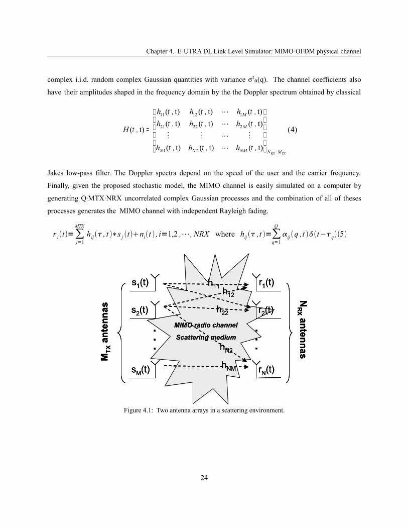
Chapter 4. E-UTRA DL Link Level Simulator: MIMO-OFDM physical channel
complex i.i.d. random complex Gaussian quantities with variance σ2α(q). The channel coefficients also
have their amplitudes shaped in the frequency domain by the the Doppler spectrum obtained by classical
Jakes low-pass filter. The Doppler spectra depend on the speed of the user and the carrier frequency.
Finally, given the proposed stochastic model, the MIMO channel is easily simulated on a computer by
generating Q·MTX·NRX uncorrelated complex Gaussian processes and the combination of all of theses
processes generates the MIMO channel with independent Rayleigh fading.
r it =∑j=1
MTX
h ij , t ∗s j t nit , i=1,2 ,⋯, NRX where hij ,t =∑q=1
Q
ij q ,t t−q5
Figure 4.1: Two antenna arrays in a scattering environment.
24
h12
.
.
....
MTX
ante
nnas
h11
h22
hNM
s1(t)
(
s2(t)
(
sM(t)
(
r1(t)
(
r2(t)
(
rN(t)
(
hN2
NR
Xantennas
MIMO radio channel
Scattering medium
h12
.
.
....
MTX
ante
nnas
h11
h22
hNM
s1(t)
(
s2(t)
(
sM(t)
(
r1(t)
(
r2(t)
(
rN(t)
(
hN2
NR
Xantennas
MIMO radio channel
Scattering medium
h12
.
.
....
MTX
ante
nnas
h11
h22
hNM
s1(t)
(
s2(t)
(
sM(t)
(
r1(t)
(
r2(t)
(
rN(t)
(
hN2
NR
Xantennas
MIMO radio channel
Scattering medium
)4(
t)(t)(t)(
t)(t)(t)(t)(t)(t)(
t)(
·21
22221
11211
TXRX MNNMNN
M
M
hhh
hhhhhh
H
,,,
,,,,,,
=,
τττ
ττττττ
τ

A Long Term Evolution Link Level Simulator
4.2. Narrowband channel model per subcarrier in MIMO-OFDM system.
OFDM divides the frequency band into Nc narrow subchannels, where Nc is the number of subcarriers;
therefore, OFDM enables to send different sequences of symbols across each subchannel.. When the
subchannel bandwidth is sufficiently narrow, the frequency response across each subchannel is
approximately flat, avoiding the need for complicated time-domain equalization and converting a
frequency-selective channel to Nc narrowband channels. Consequently, OFDM is combined with MIMO
in order to transform the frequency-selective nature of the MIMO wideband mobile channel model into Nc
parallel flat-fading subchannels and use efficient narrowband MIMO techniques.
Figure 4.2: Scheme of a MIMO-OFDM broadband system.
Figure 4.2 shows the scheme of MIMO-OFDM broadband system where a red box marks the wideband
channel and the IFFT/FFT of the OFDM transmission/reception that is equivalent to Nc narrowband
subchannels. At the transmitter, each input data stream is modulated to form a chain of modulated
symbols over subcarriers. Then, these symbols are processed by the layer mapper and precoding
processing. The OFDM modulator applies a Nc-point IFFT to Nc consecutive data symbols and then
appends the cyclic prefix (CP), which is a copy of the P last samples of the OFDM symbol, at the
beginning Therefore, the overall OFDM symbol length is Nc+P.
25
MIMO TX
Layer Mapperand
Precoding(SFBC or
Precoding)
MIMO TX
Layer Mapperand
Precoding(SFBC or
Precoding)
MQAM Modulator
MQAM Modulator
MQAM Modulator
MQAM Modulator
Single or multiuser Coded Datastreams
Nc
Nc
Nc
NcIFFTNc(+ CP)IFFTNc(+ CP)
MTX
IFFTNc(+ CP)IFFTNc(+ CP)
1MIMO
SpatialChannel
H(τ,t)
MIMOSpatial
Channel
H(τ,t)
nNRX(t)
n1(t)
FFTNc(- CP)FFTNc(- CP)
NRX
FFTNc(- CP)FFTNc(- CP)
1
MIMO RX
TRANSMIT DIVERSITY
SFBC Decoder
SPATIAL MULTIPLEXINGLinear Detector
MIMO RX
TRANSMIT DIVERSITY
SFBC Decoder
SPATIAL MULTIPLEXINGLinear Detector
1
L
1
MTX
MQAM Modulator
MQAM Modulator
MQAM Modulator
MQAM Modulator
Nc
Nc
DetectedSingle or multiuser Coded Datastreams
Narrowband channel per subcarrier Hk
MIMO Channel & SINR Estimator
MIMO Channel & SINR Estimator
Channel State Information (Close-loop)
1
NRX
1
NRX
1
MTX
1
L
s1
sMTX
x1
xNRX
MIMO TX
Layer Mapperand
Precoding(SFBC or
Precoding)
MIMO TX
Layer Mapperand
Precoding(SFBC or
Precoding)
MQAM Modulator
MQAM Modulator
MQAM Modulator
MQAM Modulator
Single or multiuser Coded Datastreams
Nc
Nc
Nc
NcIFFTNc(+ CP)IFFTNc(+ CP)
MTX
IFFTNc(+ CP)IFFTNc(+ CP)
MTX
IFFTNc(+ CP)IFFTNc(+ CP)
1
IFFTNc(+ CP)IFFTNc(+ CP)
1MIMO
SpatialChannel
H(τ,t)
MIMOSpatial
Channel
H(τ,t)
nNRX(t)
n1(t)
FFTNc(- CP)FFTNc(- CP)
NRX
FFTNc(- CP)FFTNc(- CP)
1
MIMO RX
TRANSMIT DIVERSITY
SFBC Decoder
SPATIAL MULTIPLEXINGLinear Detector
MIMO RX
TRANSMIT DIVERSITY
SFBC Decoder
SPATIAL MULTIPLEXINGLinear Detector
1
L
1
MTX
MQAM Modulator
MQAM Modulator
MQAM Modulator
MQAM Modulator
Nc
Nc
DetectedSingle or multiuser Coded Datastreams
Narrowband channel per subcarrier Hk
MIMO Channel & SINR Estimator
MIMO Channel & SINR Estimator
Channel State Information (Close-loop)
1
NRX
1
NRX
1
MTX
1
L
s1
sMTX
x1
xNRX

Chapter 4. E-UTRA DL Link Level Simulator: MIMO-OFDM physical channel
At the receiver, a AWGN noise is added to the received signal at each receive antenna and these individual
signals are passed through an OFDM demodulator which first discards the CP and then applies an FFT.
Equation (6) shows the transmitted vector s(k) with s(k)i, denoting the data symbol transmitted from the ith
antenna on the kth subcarrier. The received data vector for the kth subcarrier is given by (7) where Hk =Hk
(e(j2π/Nc)k)=Hk (f)f=k/T is the frequency response of channel H(τ,t) at kth subcarrier at time t and T is the
sample period (equation 8).
sk = s1,k s2,
k ... , sMTXk T 6
x k=H k sk nk , k=0,1,2 ,⋯,N c−17
The energy of the power delay profile of each spatial multipath channel is given by (9) and is equal to
PPDP. In case of a transmitted symbol of power 1, PPDP would be the average received symbol power. The
noise at reception is given by (10) where nk is complex-valued addtive white gaussian noise with INRX
denoting the identity matrix of size NRX and σn2 is the average noise power.
4.3. Correlation-based MIMO radio channel stochastic model
The spatial correlation model adopted in the DL link level simulator assumes the correlation between
different MIMO channel elements is modeled with the assumption that the correlation among receive
antennas is independent from the correlation between transmit antennas, and viceversa. Based on this
assumption, the spatial correlation matrix of the MIMO radio channel is the Kronecker product of the
spatial correlation matrix at the receiver (RRX) and transmitter (RTX). This stochastic MIMO radio channel
26
H k=H k f f = k
T
= h1,1k ... h1, MTX
k
⋮ hi , jk ⋮
hNRX ,1k ... hNRX , MTX
k where hi , jk =∑
q=1
Q
ij qe− j2k
q
T 8
E {hi , jk hi , j
k H }=∑q=1
Q
E {∣i , jq∣2}=∑
q=1
Q
i, j
2 q= P PDPEnergy of the Power Delay Profile
9
nk =n1,kn2,
k ... , nNRXk T where E {n p
knqk H }=n
2 I NRX [ p−q ]10

A Long Term Evolution Link Level Simulator
model was used in I-METRA project [39] and analytically demonstrated [40-41] and validated with
experimental results in [42]. The advantages and the deficiencies of the usage of a Kronecker product to
model the MIMO spatial correlation are described in [43-46]. The main advantage of this model is its
simplicity and analytical tractability, but its main drawback is that it forces both link ends to be separable,
irrespective of whether the channel supports this or not and neglects the joint spatial structure. However,
the 3GPP LTE specification determines that the correlations of the MIMO subchannels is based on
kronecker product modeling because it can be assumed that the correlations matrix can be derived as a
kronecker product between a correlation matrix seen from the base station, eNodeB, and a correlation
matrix seen from the mobile station, UE [29]. Therefore, if the correlation matrix of the eNodeB ReNodeB
and the correlation matrix of the user equipment (UE) corresponds to RTX and RRX, respectively, then the
correlation matrix of the 3GPP spatial channel model is expressed in equation (11).
TS 36.101 [21] defines the MIMO correlation matrices for the cases of 1, 2 and 4 antennas at the eNodeB
and at the UE. For instance, for the case of a 2 x 2 MIMO channel, the MIMO correlation matrix is
expressed in equation (12):
The values of α and β that defines different correlation types are given in Table 4.1 for the cases of High,
Medium and Low level correlation.
Low correlation Medium Correlation High Correlationα β α β α β0 0 0.3 0.9 0.9 0.9
Table 4.1. 3GPP LTE definition of the MIMO correlation matrix coefficients.
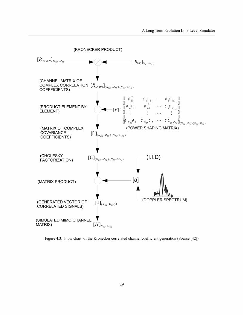
Figure 4.3 shows the flow chart illustrating the practical procedure to obtain correlated channel
coefficients for a MIMO configuration of MTX antennas at the eNodeB and NRX antennas at the UE. The
generated correlated channel coefficients of MIMO channel matrix H are obtained from the Kronecker
27
)12(
11
11
11
11
****
**
**
**
=
⊗
=⊗=
βαβαββαααα ββ
α βαβ
ββ
αα
UEeNBspat RRR
)11( UEeNBspat RRR ⊗=

Chapter 4. E-UTRA DL Link Level Simulator: MIMO-OFDM physical channel
product of correlation matrices, ReNodeB and RUE, and a vector of NRX· MTX complex zero-mean unit
variance independent random variables shaped with a Doppler spectrum. Moreover, the elements of power
shaping matrix, P, are the product of the standard deviations of the channel coefficients and enables to
model the power delay profile of the MIMO multipath channel.
Therefore, it can be derived the discrete time MIMO correlated channel model from the general equation
for the MIMO channel model (4) and (5) and the correlation matrix generated as it is illustrated in Figure
4.3. The digital sampling grid of the input samples with sampling grid spacing of ΔT gives a discrete
MIMO channel model expressed in equation (13):
If the power delay profile contains Q non-zero taps, then equation (14) shows that the convolution can be
simplified by summing only over the Q non-zero taps at the receiver ith (n=0..NRX):
Here equation (15) resolves the transmission matrix in the different delays, which can be assumed to be
common to all sub-channels. αi,j(q,n) are the correlated transmission coefficients and Pq is the power of the
qth tap derived from the power shaping matrix and assumed that all the standard deviations of the channel
coefficients at qth tap are equal:
28
(13) )(),()(1 1
∑ ∑= =
−=
∆==∆==
Q
q
M
jjiji
q
n
TX
qnsnqHnx
TqTntt
ττ
(14) )(),()(1 1
∑ ∑= =
−=Q
q
M
jjiji
TX
qnsnqHnx
(15) )(),()(
)(),(),(
1 1∑ ∑
= =
−=
⇒−=TXM
jj
Q
qijqi
ijqij
qnsnqPnx
qnnqPnqH
α
δα
Pq=ij
2 q=2 q 16
A Long Term Evolution Link Level Simulator
Figure 4.3: Flow chart of the Kronecker correlated channel coefficient generation (Source [42])
29
[a]
(I.I.D)
(DOPPLER SPECTRUM)
(KRONECKER PRODUCT)
(CHANNEL MATRIX OF COMPLEX CORRELATION COEFFICIENTS)
(PRODUCT ELEMENT BY ELEMENT)
)·)·(·(
221
222212
121211
][
TXRXTXRXTXRXRXRX
TX
TX
MNMNMNNN
M
M
P
=
σσσσσ
σσσσσσσσσσ
(POWER SHAPING MATRIX)(MATRIX OF COMPLEX COVARIANCE COEFFICIENTS)
(CHOLESKY FACTORIZATION)
(MATRIX PRODUCT)
(SIMULATED MIMO CHANNEL MATRIX)
(GENERATED VECTOR OF CORRELATED SIGNALS)
)·)·(·(][TXRXTXRX MNMNΓ
)·)·(·(][TXRXTXRX MNMNMIMOR
RXRX NNUER ·][TXTX MMeNodeBR ·][
)·)·(·(][TXRXTXRX MNMNC
1)··(][TXRX MNA
TXRX MNH ·][

Chapter 4. E-UTRA DL Link Level Simulator: MIMO-OFDM physical channel
4.4. Physical interpretation of full MIMO channel knowledge
A nice and intuitive way to visualize the physical interpretation of a given MIMO channel matrix and the
gain of the transmitter channel knowledge is by considering the singular-value decomposition (SVD, or
generalized eigenvalue decomposition) of the channel matrix H = SVD(H) = UDVH, where U and V are
unitary and D is a diagonal matrix of singular values.
Figure 4.4: Equivalence of the MIMO physical model based on SVD channel decomposition.
As shown in Figure 4.4, with linear operations at the transmitter and the receiver, that is, multiplying by V
and UH, respectively, the channel can be diagonalized. Mathematically, expressed in equations from 17 to
25, channel diagonalization can be performed by considering a detected vector sd(k) that should be close to
the input symbol vector s(k). Therefore, the complex signal precoded transmitted vector is b(k) and the
30
nNRX
(k)
MIMO Narrowband channel per subcarrier Channel
H(k)NRX x MTX
H(k)=UDVH
+
+
n1(k)
noise
Nc
s1(k)
Nc
sMTX
(k)
Nc
Nc
Ncx
1(k)
Nc
xNRX
UH NRX x NRX
Sd 1
(k)
Sd MTX
(k)
V MTX x MTX
Nc
b1
(k)
Nc
bMTX
(k)
gMTX(k)
g1(k)
Channel diagonalization equivalence based on SVD
nNRX
(k)
+
+
n1
(k)
s1(k)
sMTX
(k)
Sd 1
(k)
Sd MTX
(k)
gMTX(k)
g1(k)
λ½MTX
λ½1

A Long Term Evolution Link Level Simulator
complex signal received vector is x(k). Then, the detected vector can be written systematically from the
Singular Value Decomposition of MIMO channel complex matrix is:
where D is an NRX x MTX dimensional diagonal matrix having the singular values of channel matrix
H=H(k) on its diagonal. These singular values are the square roots of the nonzero eigenvalues of HHH or
HHH with i=1,...,Ni where Ni = rank(HHH) <= min(MTX,NRX)=MTX (as MTX<=NRX) denotes the rank
of the matrix HHH.
Dk=diag 1 ,2 , ... ,N i=1 0 ... 0
0 2 0 ⋮⋮ 0 ... 00 ... 0 N i
where 1≥2≥...≥N i24
SVD diagonalizes the channel and cancels the spatial interference without any matrix inversions or
nonlinear processing. If ith stream s(k)i is always assigned to the same ith-subchannel associated with ith-
eigenvalue, the detected ith stream sdi(k)
is, taking into account the gain at the transmitter gi:
sd i
k =ik g i
k sk nik 25
Because U(k) is unitary, U(k)Hn(k) still has the same variance as n(k). Thus, the singular-value approach does
not result in noise enhancement, as did the open-loop linear techniques.
31
bk =V k sk 17
x k=H kbknk 18
H k =SVD H k =U k DkV kH
19
sdk =U k H
x=U kH H kbknk 20
sdk =U k H
U k DkV kH
V k sk U k H nk 21
U k H
U k =I NRX V kH
V k= I MTX 22
sdk =Dk skU k H nk 23
Chapter 4. E-UTRA DL Link Level Simulator: MIMO-OFDM physical channel
4.5. MIMO Techniques
The MIMO techniques implemented in the DL MIMO-OFDM physical channel simulator are the so-
called Zero Forcing (ZF) and MMSE linear detectors for open-loop spatial multiplexing and Space
Frequency Block Coding (SFBC) with Alamouti Code at transmitter and MRC combining at the receiver
for open-loop transmit diversity.
Transmit diversity schemes exploits the independent fading in the multiple antenna links to enhance signal
diversity using the spatial dimension for adding more redundancy. Thus, transmit diversity keeps the data
rate equivalent to a SISO channel with the goal to increase robustness. When the redundancy is generated
through coding over the spatial and temporal dimension, the principle is called Space-Time Block Coding
(STBC); and consequently, over the spatial and frequency dimension is called Space-Frequency Block
Coding (SFBC), that is the case of LTE transmit diversity.
On the other hand, spatial multiplexing exploits the spatial dimension by transmitting multiple data
streams in parallel on different antennas in order to increase the achievable data rate and hence the system
capacity. In this case, the number of data streams is equal to the number of transmit antennas (MTX) and
the number of receive antennas (NRX) is equal or greater than MTX. Spatial multiplexing is optimal when
the SNR is high because the capacity grows as MTX·log(1+SNR) when SNR is high and approximately
linearly with MTX when SNR is low.
MIMO techniques can be performed with or without channel knowledge (CSI, Channel State Information)
at the transmitter. The open loop techniques assumes that the channel is known at the receiver, through
pilot symbols or other channel estimation techniques. The close loop techniques assumes that the channel
is known at both sides, the transmitter and the receiver; therefore, it can be applied a precoding matrix
based on a codebook.
32

A Long Term Evolution Link Level Simulator
4.5.1. Open Loop Spatial Multiplexing: ZF and MMSE
The baseband equivalent signal MIMO-OFDM model assumes that the bandwidth per subcarrier is so
narrow that the channel can be treated as flat-fading per subcarrier. Figure 4.5 shows the scheme of a
MIMO-OFDM spatial multiplexing with a linear receiver.
Figure 4.5: Block diagram of the MIMO Spatial Multiplexing with Linear detection.
The MIMO consists of MTX transmit antennas and NRX receive antennas, the transmitter sends a MTX-
dimensional complex signal vector s(k) for each subcarier and receiver captures a NRX-dimensional
complex vector x(k) for each subcarrier, too, that includes the additive white gaussian noise (AWGN) at the
receives. Equation (26) gives the baseband equivalent signal model that describes the relation between s(k)
and x(k) . H(k) is a NRX · MTX complex propagation matrix at subcarrier k that is assumed constant for the
duration of an OFDM symbol transmission.
The MIMO linear detectors presented in this subsection are ZF and MMSE and they are based on a
receiver matrix W(k), a MTX · NRX complex propagation matrix at subcarrier k, shown in equation (27),
that represents the linear processing to estimate the signal vector sent sd(k) .
sdk =W k xk where sd
k = sd 1k , ... , sd MTX
k T 27
The zero forcing detector (ZF) is a linear MIMO technique which sets the receiver matrix W (k) equal to
the inverse of the flat-fading channel matrix H(k) of the subcarrier k when the number of antennas at the
33
nNRX
(k)
MIMO Narrowband channel per subcarrier Channel
H(k)NRX x MTX
+
+
n1(k)
noise
Nc
s1
Nc
sMTX
Nc
Nc
Ncx
1
Nc
xNRX
W(k)MTX x NRX
Sd 1
Sd MTX
x k=H k sk nk where sk = s1,k ... , sMTX
k T , x k =x1,k ... , xNRX
k T 26

Chapter 4. E-UTRA DL Link Level Simulator: MIMO-OFDM physical channel
receiver is equal to the number of antennas at the transmitter (MTX=NRX), or more generally to the
pseudoinverse if channel matrix is not square.
W ZFk =H kH
H k−1 H kH 28
The elements of H(k) are assumed to be i.i.d.; therefore, the pseudoinverse exists when MTX is less than or
equal to NRX. Otherwise, if MTX is larger than NRX, the channel matrix is singular, its inverse does not exist
and there is no solution for the estimation of data vector sent. When the pseudoinverse exists, the zero
forcing detector removes completely the spatial interference from the transmitted signal s(k) , giving an
estimated received vector sd(k) :
sdk =W k xk =H kH
H k−1 H k H
x k =H kH
H k −1 H k H
H k I MTX
sk H k H H k −1 H kH
nk29
sdk =skH kH
H k−1 H k H nk 30
Denote the i-th component of sd(k) by sdi
(k) ,then as a final step, sdi(k)
must be rounded to the nearest
constellation point, in case of not applying channel coding. In this way, all MTX elements of s(k) can be
demodulated at the receiver. A big disadvantage of ZF detector is that it suffers from noise enhancement,
especially for badly conditioned channels which produce a high amplification of the noise. The reason of
this amplification is that the pseudoinverse inverts the eigenvalues of channel matrix H(k) and the bad
spatial subchannels with lower eigenvalues can severely amplify the noise.
A logical alternative to the zero-forcing receiver is the MMSE receiver, which attempts to strike a balance
between spatial-interference suppression and noise enhancement by simply minimizing the distortion.
Therefore, W MMSEk =argmin
W k
E {∣∣W k x k−sk ∣∣2}31
which can be derived using the well-known orthogonality principle as
W MMSEk = H k H H k
n2
s2 I MTX
−1
H k H x 32
34
A Long Term Evolution Link Level Simulator
where σ2s is the transmitted power. In other words, as the SNR grows large, the MMSE detector converges
to the ZF detector, but at low SNR, it prevents the worst eigenvalues of the channel matrix from being
inverted. Equation (32) can be rewritten as (33):
W MMSEk = H k H H kk
−1 I MTX −1 H kH
x k33
where ρk is the baseband complex signal to noise ratio at subcarrier k and it is also equal to the total
baseband complex signal to noise ratio of OFDM signal:
k= s2
n2 subcarrier K
=E {∣s i
k∣2}
E {∣n ik ∣2}
=E {∣si∣
2}
E {∣ni∣2}=
N c
2n2 ∀ k ,i si
k , n ik ∈ℂ si , ni∈ℂ
1xNc34
4.5.2. Open Loop Transmit Diversity: SFBC
E-UTRA physical layer employs the transmit diversity technique of Space Frequency Block Coding
(SFBC), that is a frequency domain version for multicarriers systems such as OFDM of the well-known
Space Time Block Coding (STBC). The Alamouti codes [51] are the simplest family of codes of all
STBCs applied to MIMO configurations of 2 antennas at the transmitter and NRX at the receiver. Alamouti
codes are a rate-1 code (without rate loss) because of their orthogonality. Therefore, after a linear receive
processing, it exist a perfect orthogonality between the symbols and there are two copies of each symbol
transmitted and NRX copies received.
Figure 4.6: Block diagram of the MIMO Trasnmit Diversity: 2x2 SFBC with Alamouti Code and MRC.
35
n2
MIMO Narrowband channel per subcarrier ChannelH(k)
2 x 2
whereH (k)=H (k+1)
+
+
n1
...s1
(k) ...
Nc/2
Nc
Nc
Nc/2
2x2 SFBC/MRC
Decoder2x2 SFBC
Encoder
Nc
Nc
...s1
(k) s2
(k) ...
...-s2
(k)* s1
(k)* ...
Subcarriers ... 2k (2k+1) ...
1
1
2
...x1(2k) x
1(2k+1) ...
...x2(2k) x
2(2k+1) ...
x1
x2
... s2
(k) ...
...sd1
(k) ...
... sd2
(k) ...

Chapter 4. E-UTRA DL Link Level Simulator: MIMO-OFDM physical channel
The mapping for the space frequency block coding (SFBC) in E-UTRA physical layer for two transmit
antennas is shown in table 4.2 [7] and the received vector signal is expressed by equation (35).
Antenna 1 Antenna 2
Subcarrier k=2j s1(j) -s2*(j)
Subcarrier k+1=2j+1 s2(j) s1*(j)
Table 4.2. LTE space frequency block code mapping
Then, at receiver side, assuming that channel coefficients are equal to two adjacent subcarriers,
H(k)=H(k+1), the space frequency block decoding after OFDM demodulation (FFT) is expressed in
equation (36) and (37) per each of 2 receiver branch:
Then, applying maximal ratio combining (MRC) between the two branches, i.e., adding (36) and (37), the
detected symbols is expressed by equation (38).
36
(38) 2)(22
2)(21
2)(12
2)(11
)(2
)(1
)(2
)(1
)(2
)(1
kkkk
kb
kb
ka
ka
kd
kd
dhhhh
ss
ss
ss
s+++
+
=
=
x12k x1
2k1
x22k x2
2k1=h11k h12
k
h21k h22
k s1k s2
k
−s2k* s1
k *n12k n1
2k1
n22k n2
2k1 35
sa1k
sa2k*= h11
k * h12k
−h21k * h22
k x12k
x12k136 sb1
k
sb2k*= h21
k * h22k
−h22k * h21
k x12k
x12k137

A Long Term Evolution Link Level Simulator
Chapter 5. UTRA DL Link Level Simulator: Channel Coding, Rate Matching and HARQ
5.1. Channel Coding and Rate Matching features
As it has been described in section 3, the E-UTRA DL link level simulator is split in two stages: the first
stage is the “MIMO-OFDM physical channel simulator” that includes the wideband OFDM
modulation/demodulation and the MIMO multipath channel and the second stage is the “Channel Coding
and Rate Matching simulator” that includes the Turbo encoder/decoder, Rate Matching and HARQ, as it is
shown in Figure 5.1. The output of the first stage is the set of the log-likelihood ratios (LLR) of the
received encoded bits. Then, the second stage filter the set of LLRs, which account for all simulated
OFDM subcarriers, to extract the LLRs of the Physical Resource Blocks (PRB) assigned to the simulated
user. In this way the time and frequency correlations of the channel response, as seen by the mobile
terminal, are properly captured.
The channel coding, rate matching ans HARQ link level simulator described in this section has been
programmed in C++ language and is based on TS.36.212 [8]. Its inputs are all the log-likelihood ratios
(LLRs) of bits of the physical channel simulations and the channel coding rate. Then, its outputs are a
realistic BER and BLER and the link level throughput look-up tables in bit/s/Hz.
37

Chapter 5. UTRA DL Link Level Simulator: Channel Coding, Rate Matching and HARQ
Figure 5.1: E-UTRA DL Link Level Simulator block diagram.
In LTE, the channel coding scheme for transport channels is Turbo Coding with a coding rate of R=1/3,
two 8-state constituent encoders and a contention-free quadratic permutation polynomial (QPP) turbo code
internal interleaver. The turbo encoder performs Trellis termination and before the turbo coding, transport
blocks are segmented into byte aligned segments with a maximum information block size of 6144 bits,
called code block. The error detection is supported by the use of 24 bit CRC. The result of the rate 1/3
turbo encoder creates three independents streams with systematic and redundant bits. These streams are
interleaved and fed to the circular buffer based on rate matching and H-ARQ procedure.
At the transmitter, rate matching is based on an algorithm that comprises 3 sub-block interleavers, one for
systematic turbo-coded bit streams and 2 for redundant turbo-coded bit streams. Then, interleaved
systematic turbo-coded bits are stored in the circular buffer contiguously and redundant turbo-coded bits
in an interlaced format. Variable coding rate is achieved by applying different puncturing patterns
depending on the current H-ARQ incremental redundancy (IR) version. Up to four IR transmissions per
code block are allowed. Then, at the other side, the receiver inverts the processing of the rate matching,
turbo coding and HARQ processes. The turbo decoder uses a MAP algorithm and a maximum of 8
decoding iterations and the HARQ process uses the ACK/NACK to detect the error free transmission.
38
Rate 1/3 turbo encoder
Random Bit Generator
BS
L1 H-ARQ & Rate Matching
QAM constellation mapping
IFFT & CP addition
MIMO Multipath Channel
QAM constellation de-mapping
CP removal & FFT
Rate 1/3 turbo decoder
L1 H-ARQ & de-rate Matching
Random Bit Generator
BLER statistitcs and link-level throughput calculation
LLR
MS
Channel Coding and Rate Matching Simulator
MIMO-OFDM physical channel
Simulator
A Long Term Evolution Link Level Simulator
When coding is applied, instead of hard decision demodulated bits, the QAM demodulator generates soft
values as inputs to the turbo decoded reflecting the reliability on each bit. According to [27] the log-
likelihood ratio (LLR) for turbo decoder concerning bit bk is defined as (39) that is the ratio between the
probability that this bit is 0 over the probability that this bit is 1 based on the knowledge of received
variable of decision, called x.
Equation (39) could be taken equivalently in symbol space (40) as [27] indicates; where sd is the detected
symbol and si|bk=0 is the set of modulation alphabet si that its k bit is 0 and si|bk=1 is the set of modulation
alphabet si that its k bit is 1.
Then, the LLR calculation could be approximated to equation (41) :
5.1. E-UTRA Turbo Coding
The E-UTRA Turbo encoder is defined in [8] and the Turbo decoder is based on a MAP decoder described
in [53]. [54] been also taken as reference to implement the Turbo encoder/decoder in the E-UTRA DL link
level simulator.
The turbo coding is a forward error correction (or channel coding) technique and its construction is based
on Parallel Concatenated Convolutional Code (PCCC), i.e., convolutional codes by forming a parallel
concatenation of two or more such codes. The scheme of LTE turbo encoder is a PCCC with two 8-state
constituent encoders and one turbo code internal interleaver and its coding rate is 1/3. Figure 5.2 shows
the structure of turbo encoder [8] where the input sequence to be encoded is called ck.
39
(39) )|1Pr()|0Pr(ln)(bit of LLR
xbxbbLb
k
kkk =
===
(40) )|Pr(
)|Pr(ln
)Pr()|Pr(
)Pr()|Pr(ln
)|Pr(
)|Pr(ln
)|1Pr()|0Pr(ln)(
1|
0|
1|
0|
1|
0|
∑∑
∑∑
∑∑
=
=
=
=
=
= ======
ki
ki
ki
ki
ki
ki
bsid
bsid
bsiid
bsiid
bsdi
bsdi
dk
dkk ss
ss
sss
sss
ss
ss
sbsbbL
(41) }|s-s{|min}|s-s{|min)( 2id0|
2id1|
−≈
== kiki bsbskbL

Chapter 5. UTRA DL Link Level Simulator: Channel Coding, Rate Matching and HARQ
Figure 5.2: Structure of rate 1/3 turbo encoder (dotted lines apply for trellis termination only)
ck is the information or systematic sequence and it is also block-interleaved before it is encoded in the
second convolution code constituent to increase the effects of coding diversity, and then, it is called ck'.
The output of a turbo code consists of outputs of each convolutional encoder as well as the original
sequence; hence, the overall code is systematic (that is, the information sequence appears at the output).
The systematic bits of the second constituent are not sent because they can be obtained in the decoder by
interleaving the original sequence sent. Then, the output from the turbo encoder called coded block
consists of 3 encoded streams, one with systematic bits, dk(0)=xk, and two with encoded bits, dk
(1)=zk and
dk(2)=zk'.
The turbo block is ended by a trellis termination and guarantees that the encoder is always at state zero at
the end of a turbo block and at the beginning of the next one. During normal operation the bits are
transmitted in the following order before multiplexing: xk,zk,zk' that corresponds to a code rate of 1/3.
Trellis termination is performed by taking the tail bits from the shift register feedback after all information
bits are encoded. The tail bits are padded after the encoding of information bits in the order of the first
40
DD D
DD D
Input Turbo code internal
interleaverOutput
Output
1st constituent encoder
2nd constituent encoder
kc
kc′
kx′
kx
kz
kz ′

A Long Term Evolution Link Level Simulator
three tail bits of the first constituent encoder: xtail_1,ztail_1, xtail_2,ztail_2 xtail_3,ztail_3; and then the second
constituent, x'tail_1,z'tail_1, x'tail_2,z'tail_2 x'tail_3,'ztail_3. So the total number of bits during trellis termination is 12.
Figure 5.3: Block diagram of the turbo decoder.
The decoding of turbo codes is based on an iterative structure constructed from MAP (maximum a
posteriori probability) algorithms for the decoding of each constituent. Figure 5.3 shows the high-level
block diagram of the turbo decoder [54] and, specifically, the MAP algorithm implemented in the DL link
level simulator has been designed with a maximum of 8 decoding iterations. The implementation of the
MAP algorithm requires the knowledge of the probability of all possible transitions in the trellis, shown in
Figure 5.4. The initial conditions to calculate these probabilities starts from the LLRs of the physical
channel simulations conditioned on the transmission of logical level 0 or logical level 1. As it has been
defined in equation (39), the log-likelihood ratio (LLR) of a given bit, bk, is defined as:
where xk is the received noisy soft sample of bk. Then, the LLR can also be written, according to Bayes
rule, as equation (43), starting from a priori information of zero and only after the first decoding iteration
it takes effect.
41
( )( ) (42)
1Prob0Prob
log)(
==
≡kk
kkk xb
xbbLLR
ConstituentDecoder #1
(MAP algorithm)
InterleaverSistematic bits
Parity bits (1st encoder)Extrinsic info.
ConstituentDecoder #2
(MAP algorithm)
De-interleaver
Parity bits (2nd encoder)
Interleaver
A priori info.
Sistematic bitsExtrinsic info.
A priori info.
Soft output (LLR)
Decodedbits 8 quantization levels
8 decoding iterations
ConstituentDecoder #1
(MAP algorithm)
InterleaverSistematic bits
Parity bits (1st encoder)Extrinsic info.
ConstituentDecoder #2
(MAP algorithm)
De-interleaver
Parity bits (2nd encoder)
Interleaver
A priori info.
Sistematic bitsExtrinsic info.
A priori info.
Soft output (LLR)
Decodedbits 8 quantization levels
8 decoding iterations8 decoding iterations

Chapter 5. UTRA DL Link Level Simulator: Channel Coding, Rate Matching and HARQ
The channel LLR can also be decomposed in two additive terms: the intrinsic information and the
extrinsic information. The intrinsic information is the LLR that depends only on the noisy sample of the
bit xk, while the extrinsic information is the LLR that depends on the adjacent bits and on the trellis
constraints. Each decoder computes the complete LLR of every bit in every iteration, but to avoid
undesirable feedback, only the extrinsic information at the output of each decoder is used as a priori
information for the next decoding process. After 8 decoding iterations, a hard decision is taken for every
bit based on the sign on the LLR, if LLR is lower than 0, the selected decoded bit is 1, otherwise, is 0.
Figure 5.4: Trellis of each 8-state constituent encoders..
42
( )( )
( )( )
nInformatio PrioriA LLR Channel
(43) 1Prob0Problog
1Prob0Prob
log)(
==+
==
≡k
k
kk
kkk b
bbxbx
bLLR
S0
S1
S2
S3
S4
S5
S6
S7
S0
S1
S2
S3
S4
S5
S6
S7
1100
00
11
01
10
10
01
11
00
01
01
10
00
11
10
Data bit=0
Coded bits
Data bit=1
S0
S1
S2
S3
S4
S5
S6
S7
S0
S1
S2
S3
S4
S5
S6
S7
1100
00
11
01
10
10
01
11
00
01
01
10
00
11
10
Data bit=0
Coded bits
Data bit=1
A Long Term Evolution Link Level Simulator
5.2. LTE Rate Matching and HARQ processes for turbo coded transport channels
The rate matching for turbo coded transport channels is defined per coded block in [8] and consists of
interleaving three information bit streams dk(0), dk(1) and dk(2), followed by the collection of bits and the
collection of bits and the generation of a circular buffer, as shown in Figure 5.4. The circular buffer based
rate matching provides a simple method of generating puncturing patterns with good performance as it is
described in [56] and [57].
Figure 5.5: Rate Matching for turbo coded transport channels [8].
Figure 5.5 shows a representation of the circular buffer where are stored the systematic and redundant
interleaved bit streams. Each stream, dk(0), dk
(1) and dk(2), is rearranged with its own sub-block interleaver
forming vk(0), vk
(1) and vk(2) , respectively. Then, a single buffer is formed by placing the rearranged
systematic bits, vk(0), in the beginning followed by interlacing the two rearranged redundant streams, vk
(1)
and vk(2) . This single buffer wk is seen as a virtual circular buffer and Bit selection and pruning selects the
number of coded bits (E) for transmission to satisfy the desired code rate of operation. The bit selection
simply reads out the first E bits beginning from a certain starting point in the buffer. If the end of the
buffer is reached, then the reading continues by wrapping around to the beginning of the buffer. Therefore,
in this way, puncturing and repetition can be achieved using this single method. Then the output streams,
43
Sub-block interleaver
Sub-block interleaver
Sub-block interleaver
Bit collection
virtual circular buffer
Bit selection and pruning
)0(kd
)1(kd
)2(kd
ke
)0(kv
)1(kv
)2(kv
kw
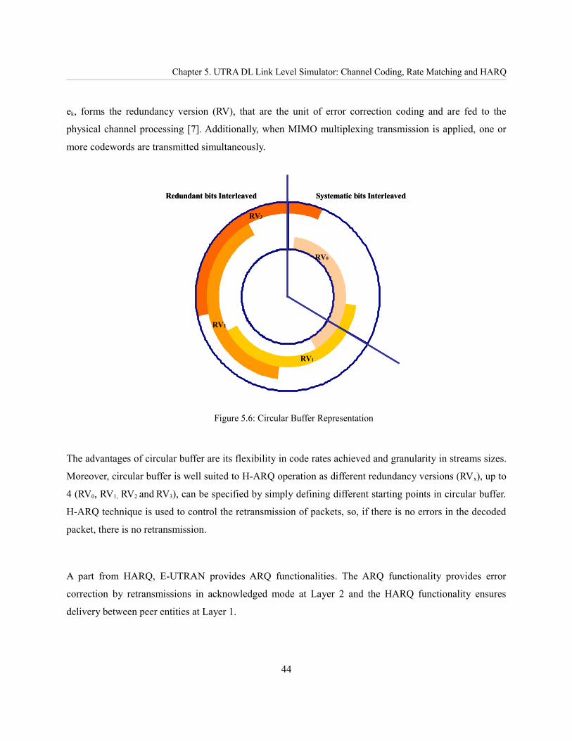
Chapter 5. UTRA DL Link Level Simulator: Channel Coding, Rate Matching and HARQ
ek, forms the redundancy version (RV), that are the unit of error correction coding and are fed to the
physical channel processing [7]. Additionally, when MIMO multiplexing transmission is applied, one or
more codewords are transmitted simultaneously.
Figure 5.6: Circular Buffer Representation
The advantages of circular buffer are its flexibility in code rates achieved and granularity in streams sizes.
Moreover, circular buffer is well suited to H-ARQ operation as different redundancy versions (RVx), up to
4 (RV0, RV1, RV2 and RV3), can be specified by simply defining different starting points in circular buffer.
H-ARQ technique is used to control the retransmission of packets, so, if there is no errors in the decoded
packet, there is no retransmission.
A part from HARQ, E-UTRAN provides ARQ functionalities. The ARQ functionality provides error
correction by retransmissions in acknowledged mode at Layer 2 and the HARQ functionality ensures
delivery between peer entities at Layer 1.
44
Systematic bits InterleavedRedundant bits Interleaved
RV0
RV1
RV2
RV3
Systematic bits InterleavedRedundant bits Interleaved
RV0
RV1
RV2
RV3

A Long Term Evolution Link Level Simulator
Chapter 6. Simulations and results
6.1. Link Level Simulator Parameters
For the simulations presented in this section, it has been assumed ideal channel estimation, a MIMO
configuration of 2 antennas at the transmitter and 2 antennas at the receiver and also a SISO configuration,
and the Extended Pedestrian A (EPA) with 3 Km/h pedestrian speed as the multipath channel model [21-
22] where its power delay profile is shown in Figure 6.1. Concerning to physical resource allocation, it has
been only considered one PRB per one simulated user, although the 3GPP specification establishes a
minimum allocation of 4 PRB for the case of 20MHz bandwidth [9]. E-UTRA turbo code block size can
be from a minimum of 40 bits to a maximum of 6144 bits and the turbo code internal interleaver
parameters are specified in [8], and a code block sizes from 40 to 120 bits have been used for the
simulations. Then, the block size for each simulation results from the size of the assigned PRB and the
code rate. Finally, Table 6.1 summarizes the parameters used for the simulations.
Figure 6.1: EPA channel Power Delay Profile
45
-25
-20
-15
-10
-5
0
0 50 100 150 200 250 300 350 400 450
Delay [ns]
Pow
er [d
B]
EPA

Chapter 6. Simulations and results
Parameter Value
Carrier frequency 2.14 GHz
Transmission Bandwidth 20 MHz
Sub-carrier spacing 15 KHz
FFT Size 2048
OFDM Cyclic Prefix CP of 4.69 μs , 7 modulation symbol/subframe
Number of Useful subcarriers 1200
OFDM symbol duration 71.43 μs
Number of sub-carriers per PRB 12
Maximum Number of PRBs 100
Number of simulated PRB per simulated user 1
Sub-frame duration 0.5 ms
TTI length 1 ms
Number of OFDM symbols per TTI 14 (4 for control)
Power Delay Profile EPA channel model, Pedestrian speed 3 Km/h
Channel Coding Turbo Code basic rate 1/3
Code block sizes 40-120 bits
Rate Matching and H-ARQ According to [8] (release 8), Max. 4 IR transmissions.
AMC formats QPSK: 1/3, 1/2, 2/3, 4/516QAM: 1/2, 2/3, 4/564QAM: 2/3, 4/5
Channels Estimation Ideal
Antenna schemes SISO 1x1 and MIMO 2x2
SISO receiver One tap equalizer
MIMO receiver ZF, MMSE and Alamouti/MRC
MIMO channel correlation Low Correlation (Uncorrelated) (LC), Medium Correlation (MC) and High Correlation (HC) according to [21]
Table 6.1.E-UTRA DL link level parameters
46
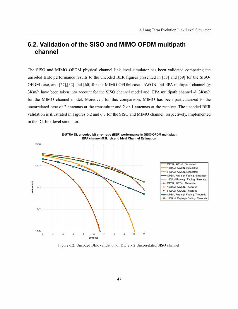
A Long Term Evolution Link Level Simulator
6.2. Validation of the SISO and MIMO OFDM multipath channel
The SISO and MIMO OFDM physical channel link level simulator has been validated comparing the
uncoded BER performance results to the uncoded BER figures presented in [58] and [59] for the SISO-
OFDM case, and [27],[32] and [60] for the MIMO-OFDM case. AWGN and EPA multipath channel @
3Km/h have been taken into account for the SISO channel model and EPA multipath channel @ 3Km/h
for the MIMO channel model. Moreover, for this comparison, MIMO has been particularized to the
uncorrelated case of 2 antennas at the transmitter and 2 or 1 antennas at the receiver. The uncoded BER
validation is illustrated in Figures 6.2 and 6.3 for the SISO and MIMO channel, respectively, implemented
in the DL link level simulator.
Figure 6.2: Uncoded BER validation of DL 2 x 2 Uncorrelated SISO channel
47
E-UTRA DL uncoded bit error ratio (BER) performance in SISO-OFDM multiplath EPA channel @3km/h and Ideal Channel Estimation
1,E-04
1,E-03
1,E-02
1,E-01
1,E+00
0 2 4 6 8 10 12 14 16 18 20
SINR[dB]
Unc
oded
BER
QPSK, AWNG, Simulated16QAM, AWGN, Simulated64QAM, AWGN, SimulatedQPSK, Rayleigh Fading, Simulated16QAM Rayleigh Fading, SimulatedQPSK, AWGN, Theoretic16QAM, AWGN, Theoretic64QAM, AWGN, TheoreticQPSK, Rayleigh Fading, Theoretic16QAM, Rayleigh Fading, Theoretic

Chapter 6. Simulations and results
Figure 6.3: Uncoded BER validation of DL 2 x 2 Uncorrelated MIMO channel
6.3. Performance of the different LTE Downlink AMC schemes with MIMO assumption
Figures 6.4, 6.5 and 6.6 shows the uncoded BER performance results of the DL link level simulations for
different modulations schemes and MIMO correlations with 2 antennas at the transmitter and 2 antennas at
the receiver that is the minimum baseline MIMO configuration of E-UTRA physical layer. The simulated
MIMO techniques are open-loop and ZF and MMSE for spatial multiplexing and SFBC (2 x 2 Alamouti/
MRC) for transmit diversity. The uncoded BER performance results get worst when the MIMO correlation
matrix coefficients rise; therefore the ideal case is the low correlation MIMO that is the uncorrelated case,
and medium and high correlation cases obtain worst results.
48
E-UTRA DL uncoded bit error ratio (BER) performance in MIMO-OFDM multiplath EPA channel @3km/h and Ideal Channel Estimation
1,E-06
1,E-05
1,E-04
1,E-03
1,E-02
1,E-01
1,E+00
0 2 4 6 8 10 12 14 16 18 20
SINR (dB)
Unc
oded
BER
Simulated QPSK 2x2 MIMO LC ZF Stream 0Simulated QPSK 2x2 MIMO LC ZF Stream 1
Simulated QPSK 2x2 MIMO LC MMSE Stream 0
Simulated QPSK 2x2 MIMO LC MMSE Stream 1Simulated QPSK MIMO 2x2 LC ALAMOUTI/MRC
Simulated QPSK 2x1 LC ALAMOUTI
Validated QPSK 2x1 LC ALAMOUTI Validated QPSK 2x2 MIMO LC ZF
Validated QPSK 2x2 MIMO LC MMSE
Validated QPSK 2x2 LC ALAMOUTI/MRC

A Long Term Evolution Link Level Simulator
Figure 6.4: Uncoded BER performance results in case of Spatial Multiplexing, ZF Detector and 2 x 2 MIMO .
Figure 6.5: Uncoded BER performance results in case of Spatial Multiplexing, MMSE Detector and 2 x 2 MIMO.
49
E-UTRA DL uncoded bit error ratio (BER) performance in MIMO-OFDM multiplath EPA channel @3km/h and Ideal Channel Estimation
1,E-03
1,E-02
1,E-01
1,E+00
-5 0 5 10 15 20
SINR [dB]
Unc
oded
BER
per
str
eam QPSK, ZF, SM, 2x2 LC
QPSK, ZF, SM, 2x2 MC QPSK, ZF, SM, 2x2 HC 16QAM, ZF, SM, 2x2 LC 16QAM, ZF, SM, 2x2 MC 16QAM, ZF, SM, 2x2 HC 64QAM, ZF, SM, 2x2 LC 64QAM, ZF, SM, 2x2 MC 64QAM, ZF, SM, 2x2 HC
E-UTRA DL uncoded bit error ratio (BER) performance in MIMO-OFDM multiplath EPA channel @3km/h and Ideal Channel Estimation
1,E-03
1,E-02
1,E-01
1,E+00
-5 0 5 10 15 20
SINR [dB]
Unc
oded
BER
per
str
eam QPSK, MMSE, SM, 2x2 LC
QPSK, MMSE, SM, 2x2 MC QPSK, MMSE, SM, 2x2 HC 16QAM, MMSE, SM, 2x2 LC 16QAM, MMSE, SM, 2x2 MC 16QAM, MMSE, SM, 2x2 HC 64QAM, MMSE, SM, 2x2 LC 64QAM, MMSE, SM, 2x2 MC 64QAM, MMSE, SM, 2x2 HC
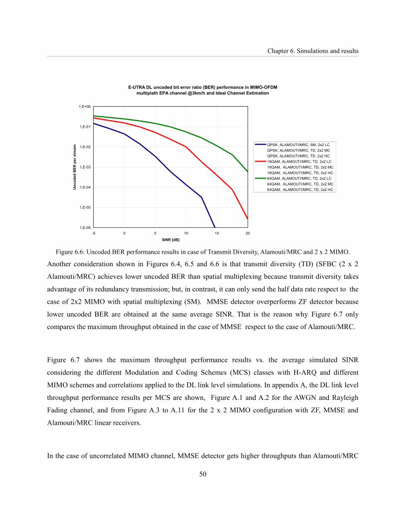
Chapter 6. Simulations and results
Figure 6.6: Uncoded BER performance results in case of Transmit Diversity, Alamouti/MRC and 2 x 2 MIMO.
Another consideration shown in Figures 6.4, 6.5 and 6.6 is that transmit diversity (TD) (SFBC (2 x 2
Alamouti/MRC) achieves lower uncoded BER than spatial multiplexing because transmit diversity takes
advantage of its redundancy transmission; but, in contrast, it can only send the half data rate respect to the
case of 2x2 MIMO with spatial multiplexing (SM). MMSE detector overperforms ZF detector because
lower uncoded BER are obtained at the same average SINR. That is the reason why Figure 6.7 only
compares the maximum throughput obtained in the case of MMSE respect to the case of Alamouti/MRC.
Figure 6.7 shows the maximum throughput performance results vs. the average simulated SINR
considering the different Modulation and Coding Schemes (MCS) classes with H-ARQ and different
MIMO schemes and correlations applied to the DL link level simulations. In appendix A, the DL link level
throughput performance results per MCS are shown, Figure A.1 and A.2 for the AWGN and Rayleigh
Fading channel, and from Figure A.3 to A.11 for the 2 x 2 MIMO configuration with ZF, MMSE and
Alamouti/MRC linear receivers.
In the case of uncorrelated MIMO channel, MMSE detector gets higher throughputs than Alamouti/MRC
50
E-UTRA DL uncoded bit error ratio (BER) performance in MIMO-OFDM multiplath EPA channel @3km/h and Ideal Channel Estimation
1,E-06
1,E-05
1,E-04
1,E-03
1,E-02
1,E-01
1,E+00
-5 0 5 10 15 20
SINR [dB]
Unc
oded
BER
per
str
eam QPSK, ALAMOUTI/MRC, SM, 2x2 LC
QPSK, ALAMOUTI/MRC, TD, 2x2 MC QPSK, ALAMOUTI/MRC, TD, 2x2 HC 16QAM, ALAMOUTI/MRC, TD, 2x2 LC 16QAM, ALAMOUTI/MRC, TD, 2x2 MC 16QAM, ALAMOUTI/MRC, TD, 2x2 HC 64QAM, ALAMOUTI/MRC, TD, 2x2 LC 64QAM, ALAMOUTI/MRC, TD, 2x2 MC 64QAM, ALAMOUTI/MRC, TD, 2x2 HC
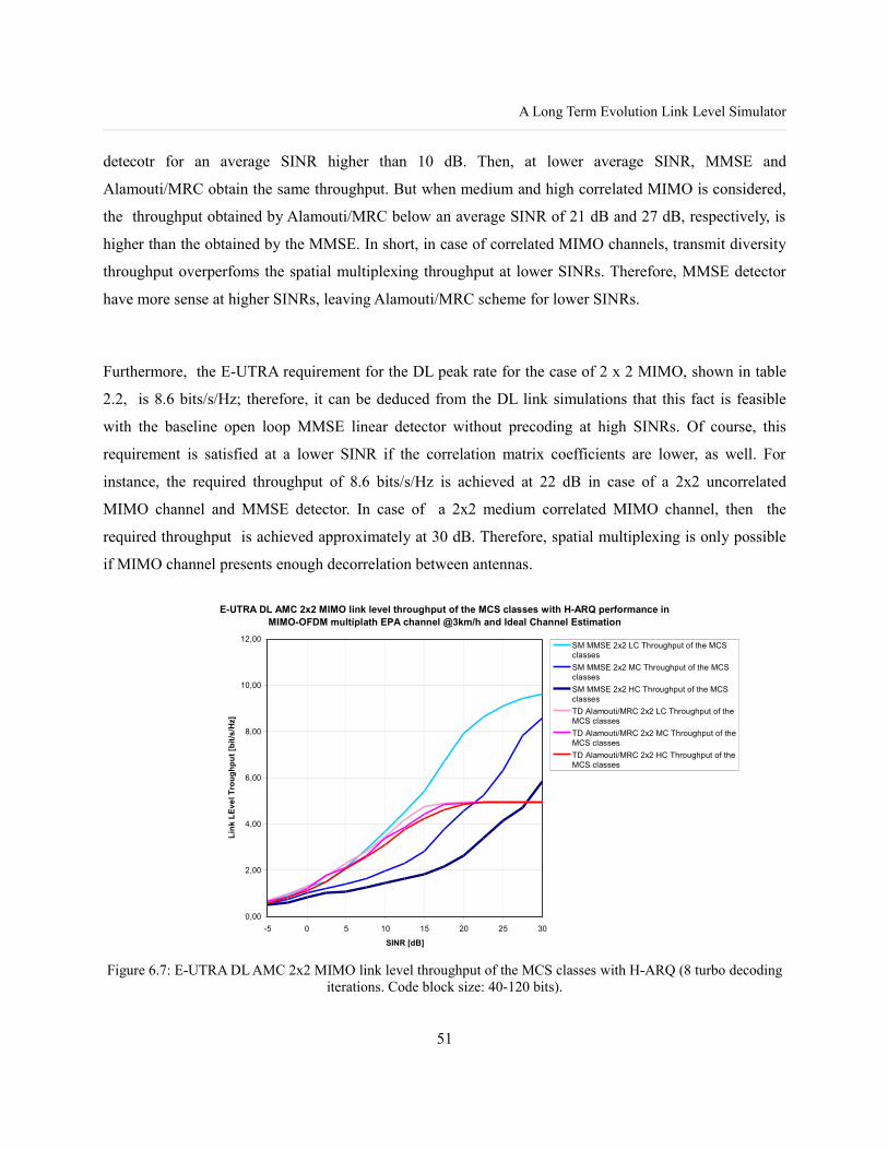
A Long Term Evolution Link Level Simulator
detecotr for an average SINR higher than 10 dB. Then, at lower average SINR, MMSE and
Alamouti/MRC obtain the same throughput. But when medium and high correlated MIMO is considered,
the throughput obtained by Alamouti/MRC below an average SINR of 21 dB and 27 dB, respectively, is
higher than the obtained by the MMSE. In short, in case of correlated MIMO channels, transmit diversity
throughput overperfoms the spatial multiplexing throughput at lower SINRs. Therefore, MMSE detector
have more sense at higher SINRs, leaving Alamouti/MRC scheme for lower SINRs.
Furthermore, the E-UTRA requirement for the DL peak rate for the case of 2 x 2 MIMO, shown in table
2.2, is 8.6 bits/s/Hz; therefore, it can be deduced from the DL link simulations that this fact is feasible
with the baseline open loop MMSE linear detector without precoding at high SINRs. Of course, this
requirement is satisfied at a lower SINR if the correlation matrix coefficients are lower, as well. For
instance, the required throughput of 8.6 bits/s/Hz is achieved at 22 dB in case of a 2x2 uncorrelated
MIMO channel and MMSE detector. In case of a 2x2 medium correlated MIMO channel, then the
required throughput is achieved approximately at 30 dB. Therefore, spatial multiplexing is only possible
if MIMO channel presents enough decorrelation between antennas.
Figure 6.7: E-UTRA DL AMC 2x2 MIMO link level throughput of the MCS classes with H-ARQ (8 turbo decoding iterations. Code block size: 40-120 bits).
51
E-UTRA DL AMC 2x2 MIMO link level throughput of the MCS classes with H-ARQ performance in MIMO-OFDM multiplath EPA channel @3km/h and Ideal Channel Estimation
0,00
2,00
4,00
6,00
8,00
10,00
12,00
-5 0 5 10 15 20 25 30
SINR [dB]
Link
LEv
el T
roug
hput
[bit/
s/H
z]
SM MMSE 2x2 LC Throughput of the MCSclassesSM MMSE 2x2 MC Throughput of the MCSclassesSM MMSE 2x2 HC Throughput of the MCSclassesTD Alamouti/MRC 2x2 LC Throughput of theMCS classesTD Alamouti/MRC 2x2 MC Throughput of theMCS classesTD Alamouti/MRC 2x2 HC Throughput of theMCS classes

Chapter 7. Conclusions and Future Work
Chapter 7. Conclusions and Future Work
A E-UTRA DL link level simulator has been developed which is split in two stages, the SISO and MIMO
OFDM physical channel simulator and the channel coding, rate matching and HARQ simulator based on
3GPP LTE specifications [7] and [8]. The goal of this simulator is to evaluate the baseline E-UTRA DL
link level and to obtain detailed E-UTRA DL link level performance results in order to properly back up to
a system level simulator.
The implementation of the MIMO OFDM physical channel simulator enables to simulate the foreseen
LTE MIMO configurations. This master thesis has presented the first average performance results of this
simulator under the case of a 2 x 2 MIMO configuration with different correlation environments at the
transmitter and at the receiver. The implemented detectors are the ZF and MMSE for spatial multiplexing
and Alamouti/MRC for the transmit diversity. Future work on this MIMO OFDM physical channel
simulator will take into account precoding matrix based on a codebook for spatial multiplexing and
transmit diversity and different PRBs allocation strategies, distributed and localized. Apart from that, the
simulation of higher MIMO configurations, such as 4x4, 4x2 and 8x8, will be necessary as they are
required by LTE advanced specifications.
The channel coding, rate matching and HARQ simulator enables to estimate the maximum average
throughput of the E-UTRA physical layer per simulated average SINR and different MCS. But, as it has
been previously mentioned in this document, these simulations do not take into account the instantaneous
performance and cannot model properly the link layer look-up table (LUT) interface to a system level
simulator. Therefore, the future work will be to construct the effective SINR (ESINR) mapping functions
based on the link level simulations of the simulator presented in this document. Then, the ESINR will be
tabulated to represent the BER functions for the instantaneous system level SINR. Finally, an E-UTRA
system level simulator will be developed and it will use the performance results of the link layer simulator.
52

A Long Term Evolution Link Level Simulator
Bibliography
[1]. 3GPP, TR 25.913, “Requirements for Evolved UTRA (E-UTRA) and Evolved UTRAN (E-UTRAN) (Release 7)”.
[2]. “UTRA-UTRAN Long Term Evolution (LTE) and 3GPP System Architecture Evolution (SAE)” [online]. URL: http://www.3gpp.org/Highlights/LTE/LTE.htm.
[3]. 3GPP, “Overview of 3GPP Release 8 V.0.0.3 (2008-11)”.[4]. 3GPP, TR 25.814, “Physical layer aspects for evolved Universal Terrestrial Radio Access (UTRA) (Release
7)”.[5]. 3GPP, TR 25.912, “Feasibility study for evolved Universal Terrestrial Radio Access (UTRA)
and Universal Terrestrial Radio Access Network (UTRAN) (Release 7)”.[6]. 3GPP TS 36.201 V8.2.0 (2008-12) , “LTE Physical Layer - General Description (Release 8)”, URL:
http://www.3gpp.org.[7]. 3GPP TS 36.211 V8.5.0 (2008-12) , “Evolved Universal Terrestrial Radio Access (E-UTRA) Physical
Channels and Modulation (Release 8)”.[8]. 3GPP TS 36.212 V8.5.0 (2008-12) , “Evolved Universal Terrestrial Radio Access (E-UTRA) Multiplexing
and channel coding (Release 8)”.[9]. 3GPP TS 36.213 V8.5.0 (2008-12), “Evolved Universal Terrestrial Radio Access (E-UTRA) Physical layer
procedure (Release 8)”.[10]. Zyren, Jim, “Overview of the 3GPP Long Term Evolution Physical Layer”, White Paper, Freescale
Semiconductor, 07/2007.[11]. Agilent, “3GPP Long Term Evolution: System Overview, Product Development and Test Challenges”.[12]. 3GPP TR 25.892 V6.0.0 (2004-06), “Feasibility Study for Orthogonal Frequency Division Multiplexing
(OFDM) for UTRAN enhancement (Release 6)”.[13]. Ramjee Prased, “OFDM for Wireless Communications Systems“, Artech House Universal Personal
Communications series, 2004.[14]. 3GPP TR 25.943 V7.0.0 (2007-06), “Deployment aspects (Release 7)”.[15]. Erik Dahlman, Anders Furuskär, Ylva Jading, Magnus Lundevall and Stefan Parkvall, “Key features of the
LTE radio interface”, Ericsson Review No.2 , 2008.[16]. Hongwei Yang, “A road to future broadband wireless access: MIMO-OFDM-Based air interface”,
Communications Magazine, IEEE, Volume 43, Issue 1, Jan. 2005.[17]. Paulraj, A.J.; Gore, D.A.; Nabar, R.U.; Bolcskei, H., "An overview of MIMO communications - a key to
gigabit wireless", Proceedings of the IEEE, Volume 92, Issue 2, Feb 2004.[18]. Stüber, G.L.; Mclaughlin; S.W., Ingram, M.A.; “Broadband MIMO-OFDM Wireless Communications”,
Proceedings of the IEEE, Volume 92, NO. 2, February 2004.[19]. Helka Määttänen, “MIMO-OFDM”, S-72.333 Postgraduate Course in Radio Communications.[20]. Jeffrey G. Andrews, Arunabha Ghosh, Rias Muhamed, “Fundamentals of WIMAX”, Prentice Hall, 2007.[21]. 3GPP TS 36.101 V8.4.0 (2008-12), “Evolved Universal Terrestrial Radio Access (E-UTRA); User
Equipment (UE) radio transmission and reception”.[22]. 3GPP TS 36.104 V8.4.0 (2008-12), “Evolved Universal Terrestrial Radio Access (E-UTRA); Base Station
(BS) radio transmission and reception”.
53

Bibliography
[23]. 3GPP TS 36.300 V8.7.0 (2008-12),”Evolved Universal Terrestrial Radio Access (E-UTRA) and Evolved Universal Terrestrial Radio Access Network (E-UTRAN); Overall description; Stage 2”
[24]. 3GPP TR 36.913 V8.0.0 (2008-06), “Requirements for further advancements for E-UTRA (LTE-Advanced)”.
[25]. Hoo-Jin Lee, Shailesh Patil, and Raghu G. Raj, "Fundamental overview and simulation of MIMO systems for Space-Time coding and Spatial Multiplexing", Wireless Networking and Communications Group (WNCG), Dept. of Electrical and Computer Engineering,The University of Texas at Austin, 2003.
[26]. L.Hanzo, M.Münster, B.J.Choi and T. keller, “Chapter 17: Uplink Detection Techniques for Multi-User SDMA-OFDM”, ”OFDM and MC-CDMA for Broadband Multi-user Communications, WLANs and Broadcasting”, John Wiley and Sons, Ltd. 2003.
[27]. Albert van Zelst, “MIMO OFDM for Wireless LANs”, PROEFSCHRIFT, April 2004.[28]. Na wei, “MIMO Techniques for UTRA Long Term Evolution”, Dissertation, September 2007. [29]. 3GPP R4-070141, “Radio Propagation Modeling for E-UTRA performance requirement definition”,
February 2007.[30]. Daniel P. Palomar, “Unified Design of Linear Transceivers for MIMO Channels”, Ph.D. Dissertation, 2003.[31]. David Gesbert, Cornelius van Rensburg, Filippo Tosato and Florian Kaltenberger, “Multiple antenna
techniques”, chapter 11 of “The UMTS Long Term Evolution: from Theory to Practice”, ISBN: 978-0-470-69716-0.
[32]. David Gesbert, Mansoor Shafi, Da-shan Shiu, Peter J. Smith and Ayman Naguib, “From Theory to Practice: An Overview of MIMO Space–Time Coded Wireless Systems”, IEEE Journal on selected areas in communications, Vol. 21, No. 3, April 2003.
[33]. Andersen, J.B., "Array gain and capacity for known random channels with multiple element arrays at both ends",Selected Areas in Communications, IEEE Journal on Volume 18, Issue 11, Nov 2000 Page(s):2172 – 2178.
[34]. B. Badic, “Space-Time Block Coding for Multiple Antenna Systems”, Dissertation, November 2005.[35]. Bertrand Muquet, Ezio Biglieri, Andrea Goldsmith, Hikmet Sari, “An Analysis of MIMO Techniques for
Mobile WiMAX Systems”, SEQUANS Communications White Paper.
[36]. Branka Vucetic, Jinhong Yuan, "Performance Limits of Multiple-Input Multiple-Output Wireless Communication Systems", Chapter 1 of Space-Time Coding, 2003 John Wiley & Sons, Ltd.
[37]. Hedayat, A.; Nosratinia, A.; Al-Dhahir, N., "Linear equalizers for flat Rayleigh MIMO channels", Proceedings. (ICASSP apos;05). IEEE International Conference on Volume 3, Issue , 18-23 March 2005.
[38]. Enrique Ulffe Whu, "MIMO-OFDM Systems for High Data Rate Wireless Networks", http://www.stanford.edu/class/ee360/Ahmad/En.pdf, Stanford University
[39]. Jean Philippe Kermoal, Laurent Schumacher, Preben Mogensen, “Channel Characterisation”, IST-2000-30148 I-METRA D2, AAU, October 2002.
[40]. Pedersen, K.I.; Andersen, J.B.; Kermoal, J.P.; Mogensen, P., "A stochastic multiple-input-multiple-output radio channel model for evaluation of space-time coding algorithms", Vehicular Technology Conference, 2000. IEEE VTS-Fall VTC 2000. 52nd Volume 2, Issue , 2000 Page(s):893 - 897 vol.2.
[41]. Jean Philippe Kermoal, “Measurement, Modelling and Performance Evaluation of the MIMO Radio Channel”, Thesis, Aalborg University, August 2002.
[42]. Jean Philippe Kermoal, Laurent Schumacher, Klaus Pedersen, Preben Mogensen and Frank Frederiksen, “A Stochastic MIMO Radio Channel Model With Experimental Validation”, IEEE Journal on selected areas in communications, Vol. 20, no. 6, August 2002.
[43]. Cheng-Xiang Wang,1 Xuemin Hong,1 Hanguang Wu,2 and Wen Xu2, "Spatial-Temporal Correlation
54

A Long Term Evolution Link Level Simulator
Properties of the 3GPP Spatial Channel Model and the Kronecker MIMO Channel Model", EURASIP Journal on Wireless Communications and Networking (2007).
[44]. Ozcelik,M.Czink, N.Bonek, E., "What makes a good MIMO channel model?",Inst. fur Nachrichtentechnik und Hochfrequenztechnik, Technische Univ. Wien, Vienna, Austria;, Vehicular Technology Conference, 2005. VTC 2005-Spring. 2005 IEEE 61st, June 2005.
[45]. Ozcelik, H.; Herdin, M.; Weichselberger, W.; Wallace, J.; Bonek, E., "Deficiencies of apos; Kroneckerapos; MIMO radio channel model",Electronics Letters Volume 39, Issue 16, 7 Aug. 2003 Page(s): 1209 – 1210.
[46]. Werner Weichselberger, Markus Herdin, Hüseyin Özcelik, Senior Member, IEEE, and Ernst Bonek, "A Stochastic MIMO Channel Model With Joint Correlation of Both Link Ends", IEEE TRANSACTIONS ON WIRELESS COMMUNICATIONS, VOL. 5, NO. 1, JANUARY 2006.
[47]. L. Schumacher, L. T. Berger and J. Ramiro-Moreno, "Recent Advances in Propagation Characterisation and Multiple Antenna Processing in the 3GPP Framework", Proceedings of 26th URSI General Assembly, Maastricht, The Netherlands, August 2002.
[48]. Henrik Asplund, Jonas medbo, Bo Göransson, Jonas karlsson, Johan Sköld, “A simplified approach to applying the 3GPP spatial channel model”, Ericsson Research, PIMRC'06.
[49]. Peter-Marc Fortune, Lajos Hanzo and Raymond Steele, “On the computation of 16.QAM and 64-QAM Performance in Rayleigh-Fading Channels”, IEICE Trans. Commun. Vol.E75-B, No.6, June 1992.
[50]. 3GPP TR 25.848 V4.0.0 (2001-03) , “Physical layer aspects of UTRA High Speed Downlink Packet Access (Release 4)”, URL: http://www.3gpp.org.
[51]. Alamouti, S.M., “A Simple Transmit Diversity Technique for Wireless Communications”, IEEE Journal on Select Areas in Communications, VOL. 16, NO. 8, OCOTBER 1998.
[52]. Stefan Kaiser, “Space Frequency Block Codes and Code Division Multiplexing in OFDM Systems”, German Aerospace Center (DLR), Institute of Communications and Navigation, GLOBECOM 2003.
[53]. Niklolic-Popovic, J. “Implementing a MAP Decoder for cdma2000 Turbo Codes on a TMS320C62x DSP Device”, Texas Instruments Application Report, 2000.
[54]. IST-2000-25133 ARROWS D08 "UTRA-FDD Simulators".[55]. Mark Stambaugh,"HARQ Process Boosts LTE Communications",Agilent Technologies Sep. 2008,
http://mobiledevdesign.com.[56]. R1-061050, "EUTRA FEC Enhancement", Motorola, France Telecom, GET, Orange, 3GPP TSG RAN
WG1#44bis,Athens, Greece. 27-31 March 2006.[57]. R1-072137, "Turbo rate-matching in LTE",Motorola, 3GPP TSG RAN1 #49,Kobe, Japan, May 07 - 11,
2007.[58]. Harada H. and Prasad, R., "Simulation and software Radio for mobile communications (+ CD)", Universal
Personal Communications, ISBN: 9781580530446,2002.[59]. Prasad, R., "OFDM for Wireless Communications Systems", Universal Personal Communications,
ISBN:1580537960, 2004.[60]. Bertrand Muquet, Ezio Biglieri and Hikmet Sari, MIMO Link Adaptation in Mobile WiMAX Systems",
WCNC 2007 proceedings.[61]. Ho Chan, Mounir Hamdi, Chui Ying Cheung and Maode Ma,"A Link Adaptation Algorithm in MIMO-
based WiMAX systems", Journal of communications, Vol 2, No. 5, August 2007.[62]. M. Surendra Raju, A. Rameshi and A. Chockalingamt, "LLR based BER Analysis of Orthogonal STBCs
using QAM on Rayleigh Fading Channels", IEEE 2004.[63]. Christoph Spiegel, Jens Berkmann, Zijian Bai1, Tobias Scholand, Christian Drewes,Guido H. Bruck,
Bertram Gunzelmann, Peter Jung,"MIMO Schemes In UTRA LTE, A Comparison",Vehicular Technology Conference, 2008. VTC Spring 2008. IEEE, 11-14 May 2008.
55

Bibliography
[64]. Spiegel, C. Berkmann, J. Zijian Bai Scholand, T. Drewes, C. Bruck, G.H. Gunzelmann, B. Jung, P.,"On MIMO for UTRA LTE", Communications, Control and Signal Processing, 2008. ISCCSP 2008. 12-14 March 2008-
[65]. Zijian Bai, Jens Berkmann, Christoph Spiegel, Tobias Scholand, Guido H. Bruck, Christian Drewes, Bertram Gunzelmann, Peter Jung,"On MIMO With Successive Interference Cancellation Applied to UTRA LTE", ISCCSP 2008, Malta, 12-14 March 2008.
[66]. R1-050903, "Description and link simulations of MIMO schemes for OFDMA based E-UTRA downlink evaluation", QUALCOMM Europe, 3GPP TSG-RAN WG1 #42, August 29th – September 2nd 2005, London, United Kingdom.
[67]. Helka-Liina Määttänen and Olav Tirkkonen and Klaus Hugl, "Orthogonalizing Transmission in MIMO with Linear Receiver and Finite MCS Set", WCNC 2008.
[68]. Na Wei, Akhilesh Pokhariyal, Christian Rom(, Basuki E. Priyanto, Frank Frederiksen, Claudio Rosa, Troels B. Sørensen, Troels E. Kolding, Preben E. Mogensen, "Baseline E-UTRA Downlink Spectral Efficiency Evaluation", Vehicular Technology Conference, 2006. VTC-2006 Fall. 2006.
[69]. Mogensen, P. Wei Na Kovacs, I.Z. Frederiksen, F. Pokhariyal, A. Pedersen, K.I. Kolding, T. Hugl, K. Kuusela, M., “LTE Capacity compared to the Shannon Bound”, Vehicular Technology Conference, 2007. VTC2007-Spring. IEEE.
[70]. Mai Tran, Angela Doufexi and Andrew Nix, “Mobile WiMAX MIMO Performance Analysis:Downlink and Uplink”, PIMRC. 2008.
56

A Long Term Evolution Link Level Simulator
Appendixes
Appendix 1. E-UTRA DL Link Level Performance Results
A1.1. E-UTRA DL Link Level Throughput
Figure A.1: E-UTRA DL AMC link level throughput with H-ARQ in AWGN SISO channel (8 turbo decoding iterations. Code block size: 40-120 bits).
57
-5 0 5 10 15 20 25 300
1
2
3
4
5
6
7
8
9
10
E-UTRA DL AMC throughput with H-ARQ performance in SISO-OFDM multiplath EPA channel @3km/h and Ideal Channel Estimation
QPSK-1/3, AWGN, 1x1, SISOQPSK-1/2, AWGN, 1x1, SISOQPSK-2/3, AWGN, 1x1, SISOQPSK-4/5, AWGN, 1x1, SISO16QAM-1/2, AWGN, 1x1, SISO16QAM-2/3, AWGN, 1x1, SISO16QAM-4/5, AWGN, 1x1, SISO64QAM-2/3, AWGN, 1x1, SISO64QAM-4/5, AWGN, 1x1, SISO
SINR [dB]
Link
Lev
el T
roug
hput
[bit/
s/Hz
]

Appendixes
Figure A.2: E-UTRA DL AMC link level throughput with H-ARQ in Rayleigh Fading SISO channel (8 turbo decoding iterations. Code block size: 40-120 bits).
Figure A.3: E-UTRA DL AMC link level throughput with H-ARQ in 2 x 2 Low Correlated MIMO channel and ZF Detector (8 turbo decoding iterations. Code block size: 40-120 bits).
58
-5 0 5 10 15 20 25 300
1
2
3
4
5
6
7
8
9
10
E-UTRA DL AMC throughput with H-ARQ performance in SISO-OFDM multiplath EPA channel @3km/h and Ideal Channel Estimation
QPSK-1/3, Rayleigh Fading, 1x1, SISOQPSK-1/2, Rayleigh Fading, 1x1, SISOQPSK-2/3, Rayleigh Fading, 1x1, SISOQPSK-4/5, Rayleigh Fading, 1x1, SISO16QAM-1/2, Rayleigh Fading, 1x1, SISO16QAM-2/3, Rayleigh Fading, 1x1, SISO16QAM-4/5, Rayleigh Fading, 1x1, SISO64QAM-2/3, Rayleigh Fading, 1x1, SISO64QAM-4/5, Rayleigh Fading, 1x1, SISO
SINR [dB]
Link
Lev
el T
roug
hput
[bit/
s/Hz
]
-5 0 5 10 15 20 25 300
1
2
3
4
5
6
7
8
9
10
E-UTRA DL AMC throughput with H-ARQ performance in MIMO-OFDM multiplath EPA channel @3km/h and Ideal Channel Estimation
QPSK-1/3, ZF, SM, 2x2 LCQPSK-1/2, ZF, SM, 2x2 LCQPSK-2/3, ZF, SM, 2x2 LCQPSK-4/5, ZF, SM, 2x2 LC16QAM-1/2, ZF, SM, 2x2 LC16QAM-2/3, ZF, SM, 2x2 LC16QAM-4/5, ZF, SM, 2x2 LC64QAM-2/3, ZF, SM, 2x2 LC64QAM-4/5, ZF, SM, 2x2 LC
SINR [dB]
Link
Lev
el T
roug
hput
[bit/
s/Hz
]

A Long Term Evolution Link Level Simulator
Figure A.4: E-UTRA DL AMC link level throughput with H-ARQ in 2 x 2 Medium Correlated MIMO channel and ZF Detector (8 turbo decoding iterations. Code block size: 40-120 bits).
Figure A.5: E-UTRA DL AMC link level throughput with H-ARQ in 2 x 2 High Correlated MIMO channel and ZF Detector (8 turbo decoding iterations. Code block size: 40-120 bits).
59
-5 0 5 10 15 20 25 300
1
2
3
4
5
6
7
8
9
10
E-UTRA DL AMC throughput with H-ARQ performance in MIMO-OFDM multiplath EPA channel @3km/h and Ideal Channel Estimation
QPSK-1/3, ZF, SM, 2x2 HCQPSK-1/2, ZF, SM, 2x2 HCQPSK-2/3, ZF, SM, 2x2 HCQPSK-4/5, ZF, SM, 2x2 HC16QAM-1/2, ZF, SM, 2x2 HC16QAM-2/3, ZF, SM, 2x2 HC16QAM-4/5, ZF, SM, 2x2 HC64QAM-2/3, ZF, SM, 2x2 HC64QAM-4/5, ZF, SM, 2x2 HC
SINR [dB]
Link
Lev
el T
roug
hput
[bit/
s/Hz
]
-5 0 5 10 15 20 25 300
1
2
3
4
5
6
7
8
9
10
E-UTRA DL AMC throughput with H-ARQ performance in MIMO-OFDM multiplath EPA channel @3km/h and Ideal Channel Estimation
QPSK-1/3, ZF, SM, 2x2 MCQPSK-1/2, ZF, SM, 2x2 MCQPSK-2/3, ZF, SM, 2x2 MCQPSK-4/5, ZF, SM, 2x2 MC16QAM-1/2, ZF, SM, 2x2 MC16QAM-2/3, ZF, SM, 2x2 MC16QAM-4/5, ZF, SM, 2x2 MC64QAM-2/3, ZF, SM, 2x2 MC64QAM-4/5, ZF, SM, 2x2 MC
SINR [dB]
Link
Lev
el T
roug
hput
[bit/
s/Hz
]

Appendixes
Figure A.6: E-UTRA DL AMC link level throughput with H-ARQ in 2 x 2 Low Correlated MIMO channel and MMSE Detector (8 turbo decoding iterations. Code block size: 40-120 bits).
Figure A.7: E-UTRA DL AMC link level throughput with H-ARQ in 2 x 2 Medium Correlated MIMO channel and MMSE Detector (8 turbo decoding iterations. Code block size: 40-120 bits).
60
-5 0 5 10 15 20 25 300
1
2
3
4
5
6
7
8
9
10
E-UTRA DL AMC throughput with H-ARQ performance in MIMO-OFDM multiplath EPA channel @3km/h and Ideal Channel Estimation
QPSK-1/3, MMSE, SM, 2x2 MCQPSK-1/2, MMSE, SM, 2x2 MCQPSK-2/3, MMSE, SM, 2x2 MCQPSK-4/5, MMSE, SM, 2x2 MC16QAM-1/2, MMSE, SM, 2x2 MC16QAM-2/3, MMSE, SM, 2x2 MC16QAM-4/5, MMSE, SM, 2x2 MC64QAM-2/3, MMSE, SM, 2x2 MC64QAM-4/5, MMSE, SM, 2x2 MC
SINR [dB]
Link
Lev
el T
roug
hput
[bit/
s/Hz
]
E-UTRA DL AMC 2x2 MIMO link level throughput with H-ARQ performance in MIMO-OFDM multiplath EPA channel @3km/h and Ideal Channel Estimation
0
1
2
3
4
5
6
7
8
9
10
-5 0 5 10 15 20 25 30
SINR [dB]
Link
Lev
el T
roug
hput
[bit/
s/H
z]
QPSK-1/3, MMSE, SM, 2x2 LCQPSK-1/2, MMSE, SM, 2x2 LCQPSK-2/3, MMSE, SM, 2x2 LCQPSK-4/5, MMSE, SM, 2x2 LC16QAM-1/2, MMSE, SM, 2x2 LC16QAM-2/3, MMSE, SM, 2x2 LC16QAM-4/5, MMSE, SM, 2x2 LC64QAM-2/3, MMSE, SM, 2x2 LC64QAM-4/5, MMSE, SM, 2x2 LC

A Long Term Evolution Link Level Simulator
Figure A.8: E-UTRA DL AMC link level throughput with H-ARQ in 2 x 2 High Correlated MIMO channel and MMSE Detector (8 turbo decoding iterations. Code block size: 40-120 bits).
Figure A.9: E-UTRA DL AMC link level throughput with H-ARQ in 2 x 2 Low Correlated MIMO channel and Transmit Diversity Alamouti/MRC (8 turbo decoding iterations. Code block size: 40-120 bits).
61
-5 0 5 10 15 20 25 300
1
2
3
4
5
6
7
8
9
10
E-UTRA DL AMC throughput with H-ARQ performance in MIMO-OFDM multiplath EPA channel @3km/h and Ideal Channel Estimation
QPSK-1/3, MMSE, SM, 2x2 HCQPSK-1/2, MMSE, SM, 2x2 HCQPSK-2/3, MMSE, SM, 2x2 HCQPSK-4/5, MMSE, SM, 2x2 HC16QAM-1/2, MMSE, SM, 2x2 HC16QAM-2/3, MMSE, SM, 2x2 HC16QAM-4/5, MMSE, SM, 2x2 HC64QAM-2/3, MMSE, SM, 2x2 HC64QAM-4/5, MMSE, SM, 2x2 HC
SINR [dB]
Link
Lev
el T
roug
hput
[bit/
s/Hz
]
-5 0 5 10 15 20 25 300
1
2
3
4
5
6
7
8
9
10
E-UTRA DL AMC throughput with H-ARQ performance in MIMO-OFDM multiplath EPA channel @3km/h and Ideal Channel Estimation
QPSK-1/3, ALAMOUTI/MRC, TD, 2x2 LCQPSK-1/2, ALAMOUTI/MRC, TD, 2x2 LCQPSK-2/3, ALAMOUTI/MRC, TD, 2x2 LCQPSK-4/5, ALAMOUTI/MRC, TD, 2x2 LC16QAM-1/2, ALAMOUTI/MRC, TD, 2x2 LC16QAM-2/3, ALAMOUTI/MRC, TD, 2x2 LC16QAM-4/5, ALAMOUTI/MRC, TD, 2x2 LC64QAM-2/3, ALAMOUTI/MRC, TD, 2x2 LC64QAM-4/5, ALAMOUTI/MRC, TD, 2x2 LC
SINR [dB]
Link
Lev
el T
roug
hput
[bit/
s/Hz
]

Appendixes
Figure A.10: E-UTRA DL AMC link level throughput with H-ARQ in 2 x 2 Medium Correlated MIMO channel and Transmit Diversity Alamouti/MRC (8 turbo decoding iterations. Code block size: 40-120 bits).
Figure A.11: E-UTRA DL AMC link level throughput with H-ARQ in 2 x 2 High Correlated MIMO channel and Transmit Diversity Alamouti/MRC (8 turbo decoding iterations. Code block size: 40-120 bits).
62
-5 0 5 10 15 20 25 300
1
2
3
4
5
6
7
8
9
10
E-UTRA DL AMC throughput with H-ARQ performance in MIMO-OFDM multiplath EPA channel @3km/h and Ideal Channel Estimation
QPSK-1/3, ALAMOUTI/MRC, TD, 2x2 MCQPSK-1/2, ALAMOUTI/MRC, TD, 2x2 MCQPSK-2/3, ALAMOUTI/MRC, TD, 2x2 MCQPSK-4/5, ALAMOUTI/MRC, TD, 2x2 MC16QAM-1/2, ALAMOUTI/MRC, TD, 2x2 MC
16QAM-2/3, ALAMOUTI/MRC, TD, 2x2 MC
16QAM-4/5, ALAMOUTI/MRC, TD, 2x2 MC
64QAM-2/3, ALAMOUTI/MRC, TD, 2x2 MC
64QAM-4/5, ALAMOUTI/MRC, TD, 2x2 MC
SINR [dB]
Link
Lev
el T
roug
hput
[bit/
s/Hz
]
-5 0 5 10 15 20 25 300
1
2
3
4
5
6
7
8
9
10
E-UTRA DL AMC throughput with H-ARQ performance in MIMO-OFDM multiplath EPA channel @3km/h and Ideal Channel Estimation
QPSK-1/3, ALAMOUTI/MRC, TD, 2x2 HCQPSK-1/2, ALAMOUTI/MRC, TD, 2x2 HCQPSK-2/3, ALAMOUTI/MRC, TD, 2x2 HCQPSK-4/5, ALAMOUTI/MRC, TD, 2x2 HC16QAM-1/2, ALAMOUTI/MRC, TD, 2x2 HC16QAM-2/3, ALAMOUTI/MRC, TD, 2x2 HC16QAM-4/5, ALAMOUTI/MRC, TD, 2x2 HC64QAM-2/3, ALAMOUTI/MRC, TD, 2x2 HC64QAM-4/5, ALAMOUTI/MRC, TD, 2x2 HC
SINR [dB]
Link
Lev
el T
roug
hput
[bit/
s/Hz
]