a low fluctuation control strategy for pmsm direct drive
TRANSCRIPT

A low fluctuation control strategy for PMSM direct drivesystem targeting Particle Beam Instrumentation Application
Jonathan Emery1, Patrik Andersson1, Federico Roncarolo1, Yann Thoma2
Abstract— Particle accelerators have a singular en-vironment where multiple constraints are driving theengineering of equipment. Designers have to deal withthe destructive effects of charged particles, high vac-uum requirements, large temperatures and particularsystem architectures due to large-scale installationssuch as the Large Hadron Collider (LHC) at theCERN laboratory. At the same time, there is a con-tinuous challenge to produce, measure and controlsmaller particle beams to increase the discovery po-tentials of large physics experiments. In this context,an innovative actuator has been built to measureprecisely the size of beams down to 150µm sigma,by moving a thin carbon wire of 30µm at about20m·s−1 through particle beams. Called Beam WireScanner (BWS), this system uses direct drive couplingto actuate a shaft inside a vacuum vessel withoutmoving parts outside it. We are reporting on thedesign and validation of its control system based ontorque control feedback as the only on-line closed-loop system to operate this instrument. The proposedstrategy keeps the smoothest action as possible on thesystem avoiding speed and position corrections thatwould lead to undesired torque variations, increasingthe uncertainty of the carbon wire position.
I. INTRODUCTION
The Beam Wire Scanner (BWS) is an electromechan-ical system coupled to a particle detector to determinethe transverse beam particles distribution inside acceler-ators. It uses a mechanism to move a thin carbon wire of30µm located in vacuum at about 20m·s−1 to go throughthe beam to produce a shower of secondary particles. Ascintillator coupled to a photomultiplier tube evaluatesthis shower. The correlation between the carbon wireposition and the number of secondary particles allowsthe determination of the beam size. Figure 1 shows thewire-scanner mechanism (left) hitting the proton beamwith its carbon wire. The scintillator (center) detectsthe shower to evaluate the transverse beam particlesdistribution versus wire position, a distribution oftenlooking like a typical Gaussian (right). The knowledge ofthe beam size is essential for accelerator operators andscientists to allow optimization of particle collisions atlarge physics experiments, such as the Compact MuonSolenoid (CMS) or A Toroidal LHC ApparatuS (ATLAS)
1J. Emery, Member, IEEE, F. Roncarolo, P. Andersson arewith the European Organization for Nuclear Research (CERN),Beam instrumentation group, Geneva, Switzerland. contact:[email protected]
2 Y. Thoma is with the REDS Institute; HEIG-VD; HES-SO //University of Applied Sciences Western Switzerland, Switzerland.
at CERN. The smaller the beams are, the higher isthe probability of collisions leading to more potentialdiscoveries.
A. Wire-scanners operational controllerThere are three types of wire scanner mechanisms in
operation across the CERN accelerators complex. Fromthe relatively small machine called Proton SynchrotronBooster (PSB) [1] [2] to the very Large Hardron Collider(LHC), all these three different types are currently usingDirect Current (DC) motors to generate the motionusing the same controller. The position closed-loop usesa rotational or linear resistive sensor, depending on thetarget motion. The trajectory is pre-calculated off-lineand is hardcoded in the controller as a look-up table.There is no dedicated control loop for the motor current.Figure 2 shows the closed-loop system. The trajectorylookup table in the controller θref is compared to themeasured position θ̂(t). The error in position eθ(t) =θ(t)− θ̂(t) feeds a simple proportional controller Gc(s) =Kc which directly provides a speed request to the dcmotor Gdc(s) using a wide bandwidth linear operationalamplifier considered perfect. The load is Gt(s) and theposition sensor is Kmθ. This architecture does not allowthe torque to be independently controlled. The speedreference directly comes from the position error, implyinga constant error tracking. This architecture operatesfor more than a decade at CERN, providing sufficientperformance for the existing mechanisms, but at the costof reliability limitation [3].
B. LHC Injectors UprgadeIn the context of the Large Hadron Collider (LHC)
Injectors Upgrade (LIU) project, a wire-scanner with
Position
Intensity
Scintillator
Beam losses Photomultiplier
Fig. 1. Wire Scanner Principle with the electromechanical part(left), the particles detector (center) and the resulting signal (right)
© 2019 IEEE. Personal use of this material is permitted. Permission from IEEE must be obtained for all other uses, in any current or future media, including reprinting/republishing this material for advertising or promotional purposes, creating new collective works, for resale or redistribution to servers or lists, or reuse of any copyrighted component of this work in other works.

𝐶𝑜𝑛𝑡𝑟𝑜𝑙𝑙𝑒𝑟 𝑃𝑙𝑎𝑛𝑡
𝐺𝑑𝑐(s) 𝐾𝑚𝜃𝐺𝑐(𝑠)𝑤(𝑡)
𝜃ref-
𝜃 (t)𝜃(𝑡) 𝜃(t)𝑒𝜃(𝑡)𝐺𝑇(s)
𝑇𝑒𝑚(t)
Fig. 2. Control architecture of the DC motor based wire-scanner
better performance than its predecessor is under design.The aim is to provide superior performance withoutthe drawback of previous generation limitations. Oldmechanisms are able to achieve precise measurements orhigh wire speed, but not both characteristics at the sametime. Table I list the specification of the upgraded sys-tem. To meet these requirements, the innovative mecha-nism integrates a Permanent Magnet Synchronous Motor(PMSM) to have all moving parts inside the vacuumpipe, where particle beams travel, while stators are onthe airside [4].
In 2015, the first prototype of this scanner was testedin the Super Proton Synchrotron (SPS) accelerator. Tocontrol this system, a controller based on field-orientedcontrol (FOC) strategy is implemented on a customelectronics hardware [5]. This system provided good per-formance and reproducibility over time. The architectureof position-speed-current feedbacks relies on the shaft po-sition for correct orientation of stator fields with respectto the shaft angle. During the operation of this system,a failure case of the controller has led to an incident thatforced the accelerator to stop for 24 hours. Such an eventhas a high-cost impact to the whole accelerators complex.Since then different solutions are under investigationto improve system reliability, including the controllersubsystem.
In 2018, for the prototype installed in the ProtonSynchrotron (PS) accelerator, a second iteration of theelectronics hardware operated the system with a differentcontroller strategy. This strategy limits closed-loop feed-backs to the minimum necessary and relies mainly on anoff-line calculation of feed-forward actions while keepingaccurate torque control. An improvement in reliably isexpected by reducing the complexity of the controller aswell as by being able to provide a higher reproducibilityof motions and smoother action to the mechanism.
II. System Description
The wire-scanner hardware has two geographicallyseparated parts; the electromechanics and detectors arestanding directly on the beamline of the accelerator, usu-ally situated underground to avoid dangerous radiationto the environment. The control and power electronicsare at the surface of accelerators to avoid damages tocomponents induced by ionizing particles.
A. Accelerator tunnel partThe electromechanics is a direct drive system
build around a Permanent Magnet Synchronous Motor(PMSM), a resolver for the absolute angular position,a magnetic braking system and an incremental highprecision optical encoder. All these elements are locatedon the same side of the shaft. At the other end of theshaft, the measuring system is made of two forks anda stretched thin carbon wire in between. The in-houseoptical fiber-based incremental encoder achieves preciseshaft angle measurement, used for the particle beam sizecalculation. The magnetic brake ensures that the systemdoes not move without power. The connection of thisscanner to its electronics is made through long coppercables up to 250m to avoid the destructive effect of thecharged particles to the electronics.
The motor is a frame-less three-phase PMSM wildlyused for high dynamic drives as it develops a high ratiotorque volume, ideal for this application. To apply thedesired torque, the system needs the rotor angle givenby the resolver to power correctly the three phases. Toachieve high performance and simple controller design,this application uses a classical Field Oriented Control(FOC) strategy. This approach allows precise control bymeans of Clarke-Park transformation [6].
The motor model equations are:d
dtid = 1
Ldud −
RsLdid + 1
Ldωe(Lqiq) (1a)
d
dtiq = 1
Lquq −
RsLdiq −
1Lqωe(Ldid + Φf ) (1b)
d
dtωm = (KT iq)− ωmB
J(1c)
d
dtθm = ωm (1d)
being ud, uq, id and iq the stator voltages and cur-rents projected on the d and q axes, Rs, Ld and Lqthe equivalent resistances and inductances, Φf the fluxgenerated by the stator, KT the motor constant, J thesystem inertia, B its damping factor and ω and θ, speedand angular position, respectively, expressed either in theelectrical or in the mechanical frame.
Fig. 3. Wire-scanner electromechanical details (courtesy of D.Gudkov)

The magnetic braking system is a custom design de-veloped for this application [7]. It uses reluctance forcesto align the shaft to predefined safe positions for thethin carbon wire to be far away from the beam. Ithas one pair of permanent magnets on the stator anda ferromagnetic rotor with one pair of teeth, allowingtwo stable angular positions. This device behaves as avariable torque disturbance that is evaluated using aFinite Element Method (FEM) software to build a look-up table (LUT) of the torque disturbance versus shaftangle Tmbs(θ). Figure 4 presents the contribution of thissystem to the torque disturbance for each shaft angle.The maximum disturbance represents about 1 N m or2% of the motor peak torque. Table I summaries theparameters used for the modelling of the system.
0 0.5 1 1.5 2 2.5 3 3.5Brake angular position [deg]
-1
-0.5
0
0.5
1
Tor
que
[Nm
]
Brake data from FEM simulationInterpolation for all profile position
0 0.5 1 1.5 2 2.5 3 3.5Scanner angular position [deg]
-50
0
50
Tor
que
[Nm
] Scanner torque without brakeScanner torque with brake
Fig. 4. Magnetic Breaking System torque in function of the shaftangle (top), and its effect on the total torque calculated to feed-forward the system (bottom)
TABLE ISystem parameters for the modelling
Characteristics Values UnitsC-Wire tangential speed Vn 20 [m·s−1]
Rotor nominal speed Wn 133 [rad·s−1]Position determination Wn 10 [µm]Motor continuous torque Tc 14.6 [N ·m]
Motor peak torque Tp 55 [N ·m]Motor Torque constant Kt 1.76 [N ·m ·A−1]
Total inertia Jt 2.59 · 10−3 [kg ·m2]Magnetic Breaking System Tmbs(θ) [N ·m]Static frictional force Tsff 0.2 [N ·m]
Dynamic friction Df 0.01 [N ·m · rad−1s−1]Cable length Lc 185 [m]
DC bus voltage Vdc 340 [V ]Control loop freq. Floop 16.129 [kHz]
Resolver accuracy 1 [deg]Optical encoder accuracy 8 [µm]
B. Accelerator surface partThe digital controller collects the angle of the shaft
with a resolver as well as with an in house optical angular
sensor based on optical fiber [8], it then calculates thenew currents for the motor three phases and activatesthe power parts using pulse-width modulation (PWM).Many state variables are recorded at the rate of 16kHzin sync with the control loop calculation. The controllersare running inside a Field Programmable Gate Array(FPGA). This type of component is very flexible andallows unlimited parallel tasks in real-time, while micro-processors have to share time between real-time tasks.
III. CONTROL DESIGNThe architecture for the controller uses Field-Oriented
Control (FOC), also called vector control. It is a variable-frequency drive (VFD) method where the stator currentsof a three-phase AC electric motor are identified as twoorthogonal components vector aligned to the rotor angleusing Clark-Park transforms. In this reference frame,there are two components: the direct d − axis and thequadrature q− axis current. The direct component pro-duces flux-weakening going against the permanent mag-nets and the quadrature component produces the torque.A coupling exist between the direct and the quadraturecurrent which needs to be reduced to apply precise andsmooth force to the system. This decoupling helps thecontroller to avoid high transients with wild spectralcomponents that can excite the natural frequencies ofthe structure including the carbon wire [9].
A. Current decouplingSince we are interested at low torque fluctuations, it is
possible to decouple the interaction between the d−axisand q − axis currents. The motor equations (1a) (1b)written in Laplace are (2a) (2b), the last contribution ofeach equation is canceled by using feedforward. For thispurpose, new inputs in Eq. (2c) and (2d) are created.
sId = 1LdUd −
RsLdId + 1
Ldω(LqIq) (2a)
sIq = 1LqUq −
RsLqIq + 1
Lqω(LqIq + φf ) (2b)
U ′d = Ud − ωe(LqIq) (2c)U ′q = Uq − ωe(LdId + φf ) (2d)
After the introduction of the decoupling bloc, thecurrent loops simplify to the following convenient first-order form:
Id = 1Lds
+RsUd (3a)
Iq = 1Lqs
+RsUq (3b)
B. Reference controllerThe first implementation of the controller uses a
torque-speed-position closed-loop topology to controleach variable individually. This implementation was suc-cessfully tested in the accelerator environment of the

Super Proton Synchrotron (SPS), giving promising re-sults [5] [6]. Figure 5 shows the controller architecture.There are three feedback loops; 1) motor currents feed-backs, 2) speed feedback, 3) position feedback. Becausethe application is primarily targeting trajectory track-ing, and to minimize the steady-state tracking error,the controller includes feed-forwards pre-calculated fora given trajectory. To decouple the dq components, afeed-forward uses the system speed to feed correctionsto the other components. The speed is calculated by aSteady-State Kalman Filter (SSKF) from the position toproduce better quality speed than a simple derivation [6].
C. Optimized controllerThe main conceptual difference between earlier work
on this wire-scanner and the controller presented in thispaper is the absence of speed and position feedback,keeping only the currents feedback and decoupling feed-forwards in charge. The goal is to simplify the controllerimplementation to increase reliability and lowering mo-tion instabilities while ensuring smooth actuation of thescanner. The online actions of the controller, i.e. theclosed-loop by feedbacks, are limited to the minimumnecessary, avoiding correction of the position and speed.These simplifications are possible since the carbon wiredoes not need to be accurately positioned along thetrajectory, but only accurately measured by a very fasthigh precision sensor. For the speed, there are minimumand maximum boundaries to respect for the correctoperation of the system. Inside this window, the speedcan vary smoothly without consequences.
Figure 6 presents the control architecture implementedfor the Proton Synchrotron (PS) wire-scanner prototype.This controller is simpler compared to the previousimplementation, focussing on the minimum necessary.Additionally to the position and speed feedback, theSSKF has been removed and the speed is directly takenfrom the Resolver to Digital Converter (RDC) inter-nal processing, providing sufficient performances for thefeed-forward decoupling of the d and q currents.
𝑃𝐼𝜃-𝜃𝑒𝑟𝑟 ω𝑐
𝑃𝐼𝜔
𝑆𝑆𝐾𝐹
𝑃𝐼𝐼𝑈𝑞
𝜃𝑟𝑒𝑓
-
+
-
+
ω𝑟𝑒𝑓 𝐼𝑟𝑒𝑓
𝜃
𝑃𝐼𝐼
𝑈𝑑0
-
Inv.Park
Park
𝐼𝑞
𝐼𝑑
𝛽
ෝ𝛼
+
+
+
Decouplers
ෞ𝜔
β
α
Inv.Clarke
Clarke
PWM GENAND
INVERTER
PMSMResolver
𝑈𝑈
𝑈𝑉
𝑈𝑊
𝐼𝑈 𝐼𝑉 𝐼𝑊
𝐼𝑈
𝐼𝑉
𝐼𝑊
𝜃
𝜃
𝜃+
-
ෞ𝜔
Fig. 5. Original control architecture used in the PSB and SPSaccelerators
D. LimitationsThis control strategy is not without drawbacks. Sup-
pressing the position and speed feedbacks reveals poten-tial modeling inaccuracies and parameters variation be-tween the systems to control. As this controller will equipmultiple replicas of the instrument, physical parametersvariation may affect the performance. Like any physicalsystem, each replica of the mechanism is having slightlydifferent behavior due to the variation of componentscharacteristics or to the way they are linked together:• System inertia• Static and dynamic frictions• Motor torque constant incertitude• Alignment motor-resolver• Finite accuracy of the resolver
The electrical drive is not part of this list since the dqcurrents are feedback to impose the expected torque,even in case of large electrical setup variations such aspower cable length or DC bus value.
Without an appropriate strategy to mitigate the con-sequences of those parameters variations, the trajectoryof the mechanism will be different for each replica, by itslength and top speed.
The basic approach to mitigate this incertitude is totune parameters for each replica. This approach wasperformed on two different replicas: one in our laboratoryand the ones inside the PS accelerator. Without adapta-tion, the acceleration and deceleration do not have thesame strength, as the system frictions are significantlydifferent. During this trial and error session, it becamealso clear that a second table was needed to account forbehavior differences between motion direction, i.e. the INbeam motion does not need the same strength than theOUT of the beam motion.
E. off-line trajectory generationThe particular constraints of operating this system
with a powerful beam motivate the nominal trajectoryto be of π rad to avoid hitting the particle beam withthe wire more than once per motion direction.
𝑃𝐼𝐼𝑈𝑞
𝜃𝑟𝑒𝑓
-
+
ω𝑟𝑒𝑓
𝐼𝑟𝑒𝑓
𝜃
𝑃𝐼𝐼
𝑈𝑑0
-
Inv.Park
Park
𝐼𝑞
𝐼𝑑
𝛽
ෝ𝛼
+
+
+
Decouplers
β
α
Inv.Clarke
Clarke
PWM GENAND
INVERTER
PMSM
𝑈𝑈
𝑈𝑉
𝑈𝑊
𝐼𝑈 𝐼𝑉 𝐼𝑊
𝐼𝑈
𝐼𝑉
𝐼𝑊
𝜃
+
-
ෞ𝜔𝑂𝑓𝑓𝑙𝑖𝑛𝑒 𝐶𝑜𝑚𝑝𝑎𝑟𝑒
𝑂𝑓𝑓𝑙𝑖𝑛𝑒 𝐶𝑜𝑚𝑝𝑎𝑟𝑒RDC Resolver
Fig. 6. Proposed control architecture for the PS accelerator

Fig. 7. Nominal trajectory of the wire-mechanism (left) and anoptimised one under consideration (right)
Figure 7 presents the forks angular positions duringa measurement cycle as presented (left), while an alter-native configuration is under consideration (right). The’HOME’ position is the initial angle, and represents thezero coordinate. The ’IN’ position is the arriving angleafter the first motion. After a defined waiting time, thesystem goes back to its initial ’HOME’ angle.
The trajectory is constructed from the 3rd derivativeof the position, known as the Jerk, to ensure smoothestforces applied to the mechanism [9]. It contains 3 phases:Pa - one sinusoid period, Pb - followed by a certain timewithout Jerk, Pc - then a sinusoid period shifted by πrad compared to Pa.
An iterative algorithm was developed to generate tra-jectories. It takes for inputs the predefined angles ofthe acceleration θa and deceleration θb and the targetspeed during the constant speed Pb, leaving the lengthof the constant speed as a free parameter. knowing thesystem inertia, frictions, and potential perturbations, itis possible to approximate the torque to be applied bythe motor. the quadratic current in the rotor frame q isdetermined by using the nominal motor torque constantKt. The parameters used with the Algorithm 1 togenerate the trajectory of the PS prototype are:ωtarget = 70[rad · s−1], θtargetacc
= θtargetdec= π
3 [rad],Jerkmin = 4e5[rad · s−3], Jerkstep = 1e3[rad · s−3],Jerkmax = 1e7[rad · s−3].
The calculation of the current q − axis look-up tableis then:
Tbrake(t) = Tmbs(θ(t)) (4a)T (t) = α(t) · Jtot + ω(t) ·Df + Tbrake(t) (4b)
Iq(t) = T (t)Kt
(4c)
Figure 8 presents the jerk curve generated with thealgorithm (top). This curve is the reference to calculatethe acceleration (second from top), the speed (3rd fromtop) and finally the position (bottom).
IV. EXPERIMENTAL VALIDATIONThe controller was implemented inside an in-house
control platform built around a field-programmable gate
Algorithm 1: Trajectory generation of the accel-eration phase Painput : ωtarget, θtarget, jerkmin, jerkstep, jerkmaxoutput: α(t), ω(t), θ(t)initialisationfor jerk ← jerkmin to jerkmax do
for timeacc ← t1 to t2 dotime(t)← 0 : tstep : timeaccjerk(t)← jerk·sin(2·pi/(timeacc)·time(t))α(t)← cumtrapz(jerk(t))ω(t)← cumtrapz(alpha(t))θ(t)← cumtrapz(omega(t))if max(θtable) ≥ θtarget then
breakend
endif max(ωtable) ≥ ωtarget then
breakend
end
array (FPGA). This system was tested in the laboratoryand in the Proton Synchrotron (PS) accelerator. Thisaccelerator is a concrete environment where the systemoperates with a distance of about 190m between themechanism and the control, one of the longest distanceforeseen. Figure 9 shows the accelerator position withthe wire-scanner installed inside its vacuum vessel. Manynearby cables make the global electromagnetic environ-ment noisy for low signals measured over long cables,such as the resolver in this application.
A. Performance evaluation methodThe experimental results of the proposed controller in
the PS accelerator are compared to field tests data of thereference controller coming from the Proton Synchrotron
0 0.01 0.02 0.03 0.04 0.05 0.06 0.07 0.08-5
0
5
Jerk
[m*s
-3] 105
0 0.01 0.02 0.03 0.04 0.05 0.06 0.07 0.08-5000
0
5000
Acc
. [m
*s-2
]
0 0.01 0.02 0.03 0.04 0.05 0.06 0.07 0.080
50
100
Spe
ed [m
*s-1
]
0 0.01 0.02 0.03 0.04 0.05 0.06 0.07 0.08time [s]
0
2
4
Pos
ition
[rad
]
Fig. 8. Motion tables generated by the algorithm with the jerk(top), the acceleration (second), the speed (third) and the position(bottom)

Fig. 9. Beam Wire Scanner prototype installed in the ProtonSynchrotron (PS)
Booster (PSB) installation. The mechanics of the scan-ners are identical for the two setups.
The performances of the controllers are evaluated us-ing their capability to minimise shot-by-shot variationfor multiples events, the repeatability, and their abilityto minimize the fluctuation of the driving force, here therotor frame q−axis current. For each data set, the meantrajectory represents the reference signal. For each event,the difference is calculated and the Standard Deviation(SD) and the Absolute Maximum (AM) is extracted.
B. ResultsThere were more than three thousand measurement
cycles performed with this controller in 2018. A subsetof two hundred cycles was processed to compare it withthe reference controller. The motion speed was limited atabout 63% of the nominal speed to protect the prototypehardware. Later on, tests near the nominal speed werepossible in the laboratory and are presented.
Figure 10 shows the motion cycles on top of each otherobtained by the presented controller. The position (top)and the speed (middle) is given by the resolver while thecurrent q − axis (bottom) is from the currents sensorsprocessed by the controller.
The performance of each dataset is evaluated using thefirst half of the motion, from the OUT position at 0 [rad]to the IN position at around 3.14 [rad]. Figure 11 presentsthe data processing of the proposed controller current inthe q − axis at the speed of 110 [rad s−1] (top) and thecomputed difference of each repetition with respect tothe mean of all events (bottom).
Table II summarizes the tracking error, defined as thedeviation from the mean, for each set of data generatedby the optimized controller (Opt) and the reference
one (Ref). There is a clear difference between thesecontrollers. While the reference controller behaves betterto track the angular position, the optimized controllerpresents a much lower shot by shot variation of theq − axis current, meaning better torque repeatabilityapplied to the mechanical system.
TABLE IIControllers tracking error
Controller events variable SD AMRef @ 133 200 0.042 0.1339Ref @ 133 9 Position 0.0278 0.068Opt @ 110 9 [rad] 0.0096 0.0274Opt @ 70 193 0.0804 0.2029Ref @ 133 200 2.3658 9.7744Ref @ 133 9 Speed 1.8106 7.8157Opt @ 110 9 [rad · s−1] 0.4394 2.322Opt @ 70 193 2.0428 6.9218Ref @ 133 200 3.9872 16.215Ref @ 133 9 current q − axis 3.2691 16.5961Opt @ 110 9 [A] 0.1149 0.7331Opt @ 70 193 0.2364 1.023
C. Time of flight verificationThe starting angle of the system varies from shot to
shot when using the proposed controller without positionfeedback. This angle determines the wire arrival timeon the particle beam. This timing is critical to measureprecise moments of the acceleration process that can lastno more than one millisecond. Figure 12 correlates themotion duration to hit the beam versus the starting angle(left). For the return motion, the timing is correlatedwith the maximum angle reached by the system. Thesedata fit well linearly, making it simple to predict the mo-tion duration using the starting angle. Another strategy
Fig. 10. Proposed controller tested in the Proton Synchrotron(PS) between the 2 and 15 October 2018. Shaft position (top), shaftspeed (middle) and the rotating reference frame stator current q for194 cycles plot on top of each other
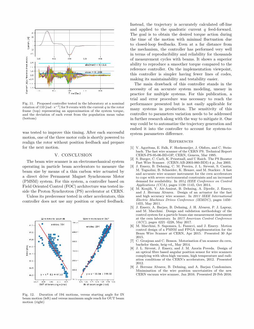
Fig. 11. Proposed controller tested in the laboratory at a nominalrotation of 110 [rad · s−1] for 9 events with the current q in the rotorframe (top) representing an approximation of the system torque,and the deviation of each event from the population mean value(bottom)
was tested to improve this timing. After each successfulmotion, one of the three motor coils is shortly powered torealign the rotor without position feedback and preparefor the next motion.
V. CONCLUSIONThe beam wire scanner is an electromechanical system
operating in particle beam accelerators to measure thebeam size by means of a thin carbon wire actuated bya direct drive Permanent Magnet Synchronous Motor(PMSM) system. For this system, a controller based onField Oriented Control (FOC) architecture was tested in-side the Proton Synchrotron (PS) accelerator at CERN.
Unless its predecessor tested in other accelerators, thiscontroller does not use any position or speed feedback.
Fig. 12. Duration of 194 motions, versus starting angle for INbeam motion (left) and versus maximum angle reach for OUT beammotion (right)
Instead, the trajectory is accurately calculated off-lineand applied to the quadratic current q feed-forward.The goal is to obtain the desired torque action duringthe time of the motion with minimal fluctuation dueto closed-loop feedbacks. Even at a far distance fromthe mechanism, the controller has performed very wellin terms of reproducibility and reliability for thousandsof measurement cycles with beams. It shows a superiorability to reproduce a smoother torque compared to thereference controller. On the implementation viewpoint,this controller is simpler having fewer lines of codes,making its maintainability and testability easier.
The main drawback of this controller stands in thenecessity of an accurate system modeling, uneasy inpractice for multiple systems. For this publication, atrial and error procedure was necessary to reach theperformance presented but is not easily applicable formany systems in production. The sensitivity of thiscontroller to parameters variation needs to be addressedin further research along with the way to mitigate it. Oneway could be to automatize the trajectory generation andembed it into the controller to account for system-to-system parameters difference.
References[1] V. Agoritsas, E. Falk, F. Hoekemeijer, J. Olsfors, and C. Stein-
bach. The fast wire scanner of the CERN PS. Technical ReportCERN-PS-95-06-BD-OP, CERN, Geneva, Mar 1995.
[2] S. Burger, C. Carli, K. Priestnall, and U Raich. The PS BoosterFast Wire Scanner. (CERN-AB-2003-060-BDI):4 p, Jun 2003.
[3] J. Emery, B. Dehning, C. M. Pereira, J. L. Sirvent, S. Cantin,M. Tognolini, B. Schneider, K. Henzer, and M. Starkier. A fastand accurate wire scanner instrument for the cern acceleratorsto cope with severe environmental constraints and an increaseddemand for availability. In 2014 IEEE Conference on ControlApplications (CCA), pages 1139–1145, Oct 2014.
[4] M. Koujili, Y. Ait-Amirat, B. Dehning, A. Djerdir, J. Emery,and J. Herranz Alvarez. Design of an actuator for the fastand high accuracy wire scanner. In 2011 IEEE InternationalElectric Machines Drives Conference (IEMDC), pages 1450–1455, May 2011.
[5] J. Emery, A. Barjau, B. Dehning, J. H. Alvarez, P. J. Lapray,and M. Macchini. Design and validation methodology of thecontrol system for a particle beam size measurement instrumentat the cern laboratory. In 2017 American Control Conference(ACC), pages 4221–4228, May 2017.
[6] M. Macchini, S. Saponara, L. Fanucci, and J. Emery. Motioncontrol design of a PMSM and FPGA implementation for theBeam Wire Scanner at CERN, Apr 2015. Presented 30 Apr2015.
[7] C. Grosjean and C. Besson. Motorisation d’un scanner du cern,bachelor thesis, heig-vd„ May 2014.
[8] J. L. Sirvent, J. Emery, and J. M. Azorin Poveda. Design ofan optical fibre based angular position sensor for wire scannerscomplying with ultra-high vacuum, high temperature and radi-ation conditions of the CERN’s accelerators, 2012. Presented2012.
[9] J. Herranz Alvarez, B. Dehning, and A. Barjau Condomines.Minimisation of the wire position uncertainties of the newCERN vacuum wire scanner, Jan 2016. Presented 29 Feb 2016.