a miniature low-power sensor system for real time 2d ... · reporting frames of pixel illuminations...
TRANSCRIPT

Abstract — Humans effortlessly estimate positions of nearby objects in real time purely based on visual perception; a capability that is desirable for many real world robotic scenarios, such as a mobile robot approaching a target, or a robot arm reaching for human-placed objects. Today, such vision based object tracking requires significant computational efforts even for clearly marked objects, because of challenges in real time processing of huge amounts of – mainly redundant – image data (e.g. handling unknown illuminations, disentangling objects from cluttered background). Small autonomous robots typically cannot provide sufficient on-board processing power for visual object tracking. This paper presents a biologically inspired miniature sensor system for real time visual object tracking at rates of several 100 Hz, while utilizing only minimal computing resources. The system combines two functionally separate components: (I) a recently developed Dynamic Vision Sensor Chip (DVS), which - instead of transmitting full image frames at fixed time intervals - asynchronously emits “spike events” that are caused by temporal changes of illumination at individual pixels. Such biologically inspired information encoding drastically reduces the amount of data to be processed compared to traditional video cameras, and significantly increases time resolution. The other component (II) is a 32bit 64MHz microcontroller with 64KB on-board SRAM, which executes an event-based algorithm to track marked objects (here high-frequency flashing LEDs) in real-time, based on the DVS’ output stream of spike events. The complete miniature sensor system requires less than 200mW power to autono-mously track markers in real-time at well above 100Hz update rates, for a cost below 10US$ if produced in large quantities. This paper presents the asynchronous event-based tracking algorithm and evaluates the sensor system’s performance in real world robotics scenarios.
I. INTRODUCTION
Reliable visual tracking of multiple nearby objects is a common demand in robotic applications, ranging from miniaturized autonomous mobile robots to large industrial settings, [1]-[3]. Several workshops – often within the scope of human robot interaction – and immense software development efforts have been devoted to this topic, e.g. http://pets2010.net and http://opentl.org. Today’s solutions for visual object tracking typically are divided into three Manuscript received August 10th, 2011. This work was supported in part by the DFG Cluster of Excellence “Cognition for Technical Systems” (http://www.cotesys.de) and the chair of Automation and Autonomous Systems at Technische Universität München (http://www.lsr.ei.tum.de).
G.R.M. is with the Department of Mechanical Engineering, Technische Universität München, Germany (e-mail: [email protected])
J.C. is with the Department of Electrical Engineering, Technische Universität München, Fachgebiet Neurowissenschaftliche Systemtheorie, Institute for Automation and Autonomous Systems, Arcisstr. 21, 80333 München, Germany (phone +49 89 289 26925, fax: +49 89 289 26913, e-mail: [email protected]).
categories: (a) using active sensors (e.g. Microsoft’s Kinect); (b) using active markers, often referred to as “beacons”; and (c) marker-less passive systems, such as a video camera tracking arbitrary objects. Although the most flexible of these - (c) - would be preferred in most scenarios, today’s existing implementations require substantial computing resources (typically at least a desktop PC), and are therefore poorly matched for small autonomous robot applications.
This research project developed a system of type (b), which is composed of various active LED markers and a passive vision sensor. Such a tracking system can well be applied in settings where mobile agents have to preserve energy and/or need to constrain their computing resources for size or weight reasons, but operate in well prepared, possibly dynamic environments. Examples of such are industrial path-following mobile delivery robots or robotic arms for reaching and grasping in human/robot co-working scenarios. It is not the scope of this paper to advance the latest visual tracking and servoing algorithms, but to present a conceptually simple, cheap, fast, and low-power stand-alone visual tracking solution, which can well serve as front-end sensor for state-of-the-art tracking and servoing algo-rithms, as e.g. outlined in [4], [5].
Today’s vision based tracking systems, from web cameras to expensive research or movie industry equipment, typically provide 30 image frames per second at resolutions of several 100ds of thousands of pixels. This is an enormous amount of (mainly redundant) data to be processed in real-time windows of about 33ms each. Image blur due to camera motion, unpredictable illumination, reflections, and cluttered environments may further complicate reliable visual tracking. As an alternative sensor system which circumvents such difficulties, we present tracking algorithms for a biologically inspired vision sensor, which instead of reporting frames of pixel illuminations in fixed time intervals rather reports changes of illumination asynchronously for every pixel (Chapters II.A, II.B). Besides increasing the timing resolution to microsecond precision, this sensor also drastically reduces the amount of data to be processed, such that a tiny standalone ARM7 microcon-troller has been shown to track moving objects in real-time in otherwise stationary environments [6]. Chapter III presents and evaluates computationally efficient algorithms for tracking high-frequent blinking LED markers, which in Chapter IV are applied in two exemplary real-world robotic tasks. The paper finishes with a discussion, conclusions and a general outlook.
A Miniature Low-Power Sensor System for Real Time 2D Visual Tracking of LED Markers
Georg R. Müller, Jörg Conradt, Member, IEEE
II. THE SYSTEM’S TRACKING HARDWARE This section describes the vision sensor and the embedded processing hardware.
A. The Dynamic Vision Sensor The Dynamic Vision Sensor Chip (DVS, [7], [8]) used in this project is an address-event silicon retina that responds to temporal contrast (Figure 1, Table 1). Each output spike address represents a quantized change of log intensity at a particular pixel since the last event from that pixel. The address includes a sign bit to distinguish positive from negative changes (on vs. off events). All 128x128 pixels operate asynchronously and signal illumination changes within a few microseconds after occurrence. No frames of “complete” images exist in the system, but instead only individual events that signal changes at a particular spatial position denoted by a particular pixel’s address.
Figure 1: DVS pixel and camera architecture. Each DVS pixel outputs events (encoded as addresses) that represent quantized log intensity changes, as shown by the simplified pixel schematic.
TABLE 1: THE DVS’S ELECTRICAL SPECIFICATIONS Dynamic range 120dB Contrast threshold mismatch 2.1% Pixel array size 128x128 pixels of (40u)2 Photoreceptor bandwidth >= 3KHz Event saturation rate 1 M-event per second Power consumption 23mW
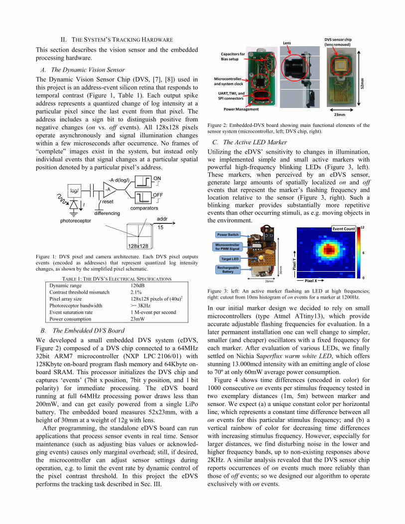
B. The Embedded DVS Board We developed a small embedded DVS system (eDVS, Figure 2) composed of a DVS chip connected to a 64MHz 32bit ARM7 microcontroller (NXP LPC 2106/01) with 128Kbyte on-board program flash memory and 64Kbyte on-board SRAM. This processor initializes the DVS chip and captures ‘events’ (7bit x position, 7bit y position, and 1 bit polarity) for immediate processing. The eDVS board running at full 64MHz processing power draws less than 200mW, and can get easily powered from a single LiPo battery. The embedded board measures 52x23mm, with a height of 30mm at a weight of 12g with lens.
After programming, the standalone eDVS board can run applications that process sensor events in real time. Sensor maintenance (such as adjusting bias values or acknowled-ging events) causes only marginal overhead; still, if desired, the microcontroller can adjust sensor settings during operation, e.g. to limit the event rate by dynamic control of the pixel contrast threshold. In this project the eDVS performs the tracking task described in Sec. III.
Figure 2: Embedded-DVS board showing main functional elements of the sensor system (microcontroller, left; DVS chip, right).
C. The Active LED Marker Utilizing the eDVS’ sensitivity to changes in illumination, we implemented simple and small active markers with powerful high-frequency blinking LEDs (Figure 3, left). These markers, when perceived by an eDVS sensor, generate large amounts of spatially localized on and off events that represent the marker’s flashing frequency and location relative to the sensor (Figure 3, right). Such a blinking marker provides substantially more repetitive events than other occurring stimuli, as e.g. moving objects in the environment.
Figure 3: left: An active marker flashing an LED at high frequencies; right: cutout from 10ms histogram of on events for a marker at 1200Hz.
In our initial marker design we decided to rely on small microcontrollers (type Atmel ATtiny13), which provide accurate adjustable flashing frequencies for evaluation. In a later permanent installation one can well change to simpler, smaller (and cheaper) oscillators with a fixed frequency for each marker. After evaluation of various LEDs, we finally settled on Nichia Superflux warm white LED, which offers stunning 13.000mcd intensity with an emitting angle of close to 70º at only 60mW average power consumption.
Figure 4 shows time differences (encoded in color) for 1000 consecutive on events per stimulus frequency tested in two exemplary distances (1m, 5m) between marker and sensor. We expect (a) a unique constant color per horizontal line, which represents a constant time difference between all on events for this particular stimulus frequency; and (b) a vertical rainbow of color for decreasing time differences with increasing stimulus frequency. However, especially for larger distances, we find disturbing noise in the lower and higher frequency bands, up to non-existing responses above 2KHz. A similar analysis revealed that the DVS sensor chip reports occurrences of on events much more reliably than those of off events; so we designed our algorithm to operate exclusively with on events.
DVS sensor chip(lens removed)Lens
Capacitors for Bias setup
Microcontroller and system clock
UART, TWI, and SPI connectors
Power Management23mm
52mm
26mm36mm
Target LED
RechargeableBattery
Microcontrollerfor PWM Signal
Power Switch
0
6
12
Pixel X
Pixel Y
Event Count

Figure 4: Color-encoded on event time differences for varying stimulus frequencies (vertical axis) at two exemplary distances d=1m and d=5m. Horizontal rows of constant colors indicate constant event time differences.
The overall result, however, clearly shows that we can reliably detect the frequency of on occurrences from around 500Hz up to well above 1,5KHz.
III. EVENT-BASED TRACKING ALGORITHMS This chapter presents two visual tracking algorithms that run in real-time on eDVS hardware described in Chapter II.B.
A. Marker Tracking by Event-Counting A naïve but efficient approach to estimate the origin of a blinking light source within the eDVS’ pixel array is coun-ting the number of events that occur at any pixel location within a fixed time window. The available frequency range of reliable markers (between 500 and 1500Hz, as estimated in Chapter II.C) suggests recording windows of 10ms, which correspond to 5-15 expected events per time frame and results in an update rate of 100Hz for tracked positions. Analyzing the noise in Figure 4 reveals that markers with a band distance of ≥300Hz (three events within 10ms) will get reliably classified. The algorithm is depicted in Figure 5: Each incoming event at a pixel (green) increases one out of 128x128 dedicated counter registers. After the defined time window elapsed, the one counter closest to the expected value (blue circle) indicates the winning location, and therefore the direction in which to expect the marker. All counters are cleared (reset) before a new iteration starts.
Figure 5: Tracking by counting events: each incoming event (green) updates the counter at its pixel location; a new most likely position estimate results after a fixed time window (blue).
This chapter presented a simple yet effective algorithm for visual tracking of active markers, which runs on low-power microcontrollers with update rates of up to 100 estimations per second.
B. A Frameless Time-Difference Algorithm The above algorithm only computes marker positions after time elapsed, which here limits the tracking rate to 100Hz. A particular advantage of the event based dynamic vision sensor (eDVS) is its asynchronous operation, which allows immediate update of a marker’s tracked position for every perceived event from that marker. This chapter presents our algorithm to rapidly update a marker’s position for every incoming event, based on the event’s temporal coherence and spatial vicinity to the current tracked marker position.
The active LED markers (chapter II.C) emit light blinking at user-defined frequencies, with each toggling of an LED causing an on or off event respectively, perceived by a sensor’s pixel. We can safely assume that those events occur significantly more regularly in time compared to events caused by “arbitrary” sources (e.g. moving contours). Therefore, the temporal difference between consecutive on events perceived by a pixel provides an indication of how likely those events have been generated by our marker.
Our algorithm keeps track of the time of occurrence of the last on event for every pixel in a 128x128 matrix (Figure 6, right, green track). For every incoming event the algorithm computes the event time difference ΔtE between current time (tE) and memorized time (last on event, tM):
ΔtE = tE - tM (here 5612μs - 4600μs = 1012μs).
The difference between measured time difference ΔtE and expected time difference ΔtEXP (here 1000μs for 1000Hz marker) is computed as time deviation tD:
tD = ΔtE - ΔtEXP (here 1012μs - 1000μs = 12μs).
This absolute time deviation tD in microseconds indicates how “correct” the event time of a particular incoming event is with respect to the previous event at the same pixel. We apply a Gaussian function [GT: -∞..+∞ → 0..1] to obtain a time based weighting factor wT for every event, which penalizes large time deviations. The variance of GT serves as free parameter to adjust the algorithm’s sensitivity to jitter in time. The obtained time weighting factor wT therefore indicates how relevant an incoming event is for tracking based on temporal coherence.
Besides temporal coherence, spatial vicinity impacts an event’s relevance for tracking updates: as we are tracking real world objects we expect spatially continuous motion rather than abrupt position changes (note: we exclude the special case of tracking temporarily occluded markers). We introduce a further weighting factor wP for spatial vicinity: The Cartesian distance of a new event’s pixel position PE with respect to the currently tracked position PT, again processed by a Gaussian [GP: 0..+∞ → 0..1], indicates an event’s relevance for tracking based on spatial consistency (Figure 6, left, red track).
500
1000
1500
2000
2500Targ
et L
ED B
linki
ng F
requ
ency
[Hz]
3000
2000
1000
500
0
2500
1500
Col
or-e
ncod
ed ti
me-
diffe
renc
ebe
twee
n co
nsec
utiv
e on
-eve
nts
[μs]
event index event index
Distance d=1m d=5m
128x128
eDVS Counter Memory(b) reset all bins to “zero”
(a) extract targetin sensor coordinates
every 10ms
128x128
eDVS Pixel MatrixTarget Marker
0 1 0 0 2
0 2 4 0 0
0 5 9 7 1
1 2 5 1 0
0 0 0 3 0
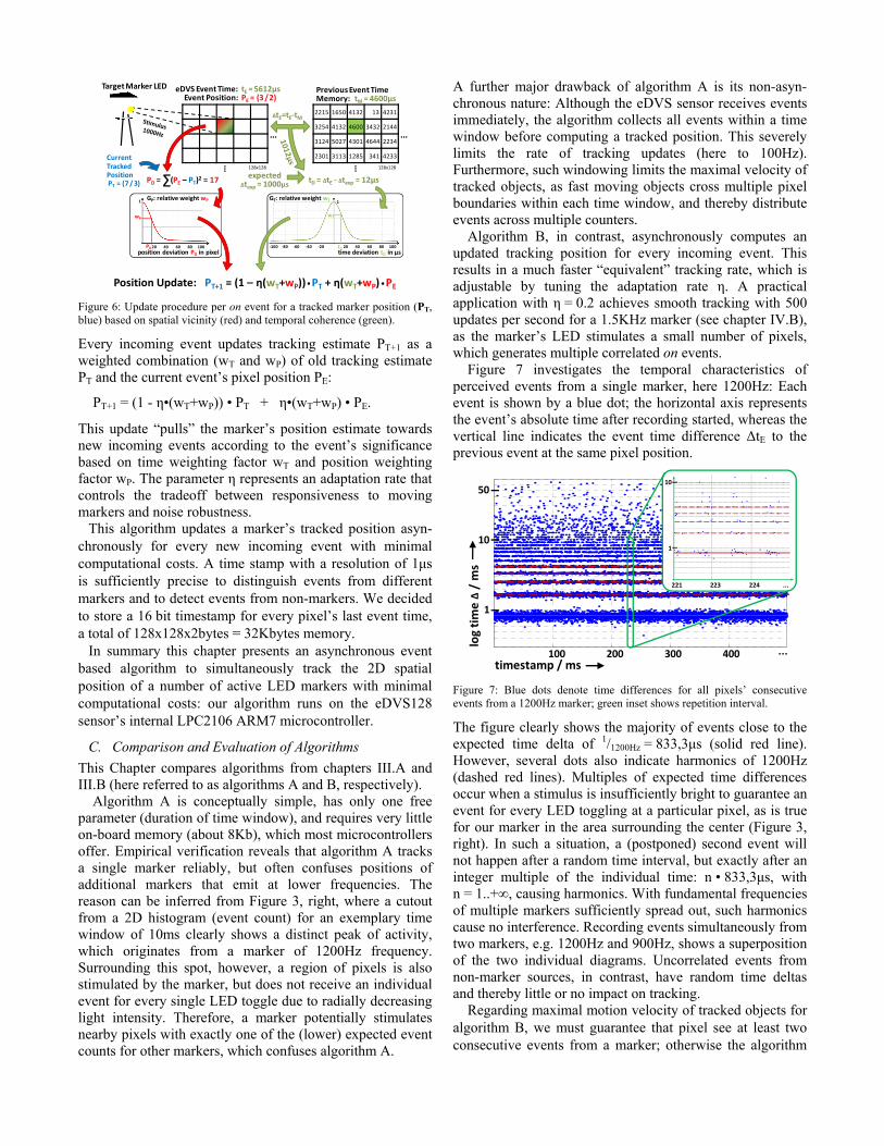
Figure 6: Update procedure per on event for a tracked marker position (PT, blue) based on spatial vicinity (red) and temporal coherence (green).
Every incoming event updates tracking estimate PT+1 as a weighted combination (wT and wP) of old tracking estimate PT and the current event’s pixel position PE:
PT+1 = (1 - η•(wT+wP)) • PT + η•(wT+wP) • PE.
This update “pulls” the marker’s position estimate towards new incoming events according to the event’s significance based on time weighting factor wT and position weighting factor wP. The parameter η represents an adaptation rate that controls the tradeoff between responsiveness to moving markers and noise robustness.
This algorithm updates a marker’s tracked position asyn-chronously for every new incoming event with minimal computational costs. A time stamp with a resolution of 1μs is sufficiently precise to distinguish events from different markers and to detect events from non-markers. We decided to store a 16 bit timestamp for every pixel’s last event time, a total of 128x128x2bytes = 32Kbytes memory.
In summary this chapter presents an asynchronous event based algorithm to simultaneously track the 2D spatial position of a number of active LED markers with minimal computational costs: our algorithm runs on the eDVS128 sensor’s internal LPC2106 ARM7 microcontroller.
C. Comparison and Evaluation of Algorithms This Chapter compares algorithms from chapters III.A and III.B (here referred to as algorithms A and B, respectively). Algorithm A is conceptually simple, has only one free parameter (duration of time window), and requires very little on-board memory (about 8Kb), which most microcontrollers offer. Empirical verification reveals that algorithm A tracks a single marker reliably, but often confuses positions of additional markers that emit at lower frequencies. The reason can be inferred from Figure 3, right, where a cutout from a 2D histogram (event count) for an exemplary time window of 10ms clearly shows a distinct peak of activity, which originates from a marker of 1200Hz frequency. Surrounding this spot, however, a region of pixels is also stimulated by the marker, but does not receive an individual event for every single LED toggle due to radially decreasing light intensity. Therefore, a marker potentially stimulates nearby pixels with exactly one of the (lower) expected event counts for other markers, which confuses algorithm A.
A further major drawback of algorithm A is its non-asyn-chronous nature: Although the eDVS sensor receives events immediately, the algorithm collects all events within a time window before computing a tracked position. This severely limits the rate of tracking updates (here to 100Hz). Furthermore, such windowing limits the maximal velocity of tracked objects, as fast moving objects cross multiple pixel boundaries within each time window, and thereby distribute events across multiple counters.
Algorithm B, in contrast, asynchronously computes an updated tracking position for every incoming event. This results in a much faster “equivalent” tracking rate, which is adjustable by tuning the adaptation rate η. A practical application with η = 0.2 achieves smooth tracking with 500 updates per second for a 1.5KHz marker (see chapter IV.B), as the marker’s LED stimulates a small number of pixels, which generates multiple correlated on events.
Figure 7 investigates the temporal characteristics of perceived events from a single marker, here 1200Hz: Each event is shown by a blue dot; the horizontal axis represents the event’s absolute time after recording started, whereas the vertical line indicates the event time difference ΔtE to the previous event at the same pixel position.
Figure 7: Blue dots denote time differences for all pixels’ consecutive events from a 1200Hz marker; green inset shows repetition interval.
The figure clearly shows the majority of events close to the expected time delta of 1/1200Hz = 833,3μs (solid red line). However, several dots also indicate harmonics of 1200Hz (dashed red lines). Multiples of expected time differences occur when a stimulus is insufficiently bright to guarantee an event for every LED toggling at a particular pixel, as is true for our marker in the area surrounding the center (Figure 3, right). In such a situation, a (postponed) second event will not happen after a random time interval, but exactly after an integer multiple of the individual time: n • 833,3μs, with n = 1..+∞, causing harmonics. With fundamental frequencies of multiple markers sufficiently spread out, such harmonics cause no interference. Recording events simultaneously from two markers, e.g. 1200Hz and 900Hz, shows a superposition of the two individual diagrams. Uncorrelated events from non-marker sources, in contrast, have random time deltas and thereby little or no impact on tracking.
Regarding maximal motion velocity of tracked objects for algorithm B, we must guarantee that pixel see at least two consecutive events from a marker; otherwise the algorithm
eDVS Event Time: tE =5612μsEvent Position: PE = (3/2)
Previous Event TimeMemory: tM = 4600μs
Target Marker LED
expectedΔtexp = 1000μs
2215 1650 4132 13 4231
3254 4132 4600 3432 2144
3124 5027 4301 4644 2234
2301 3113 1285 341 4233
…
…
128x128
tD = ΔtE ‐ Δtexp = 12μs
ΔtE=tE‐tM
20 40 60 80 100‐100 ‐80 ‐60 ‐40 ‐20
1
tD
wT
time deviation tD in μs
GT: relative weight wT
Position Update: PT+1 = (1 – η(wT+wP))•PT + η(wT+wP)•PE
20 40 60 80 100
1
PD
wP
position deviation PD in pixel
GP: relative weight wP
PD = (PE – PT)2 = 17ΣCurrentTrackedPositionPT = (7/3)
…
…
128x128
timestamp / ms100 200 300 ...400
1
10
log time Δ/ ms
50
223 224
1
10
221 ...

cannot estimate time differences ΔtE. Compared to algorithm A, however, this allows up to a ten-fold increase in object velocity; we can furthermore intentionally assign markers with high frequencies to fast moving objects, and those markers with lower frequencies to slower objects. A potential drawback of algorithm B is a relatively large number of free parameters that need to be tuned: ηP, ηT (tracking adaptation rate) and σP, σT (standard deviation of Gaussians). In practice, the algorithm is relatively insensitive to these parameters, if tracked objects move slowly across pixels with respect to the blinking frequency. However, for the second following application scenario, careful parameter tuning was essential (see chapter IV.B).
In summary, algorithm B requires slightly more on-board memory; but is superior to algorithm A in terms of noise robustness, high update frequency, tolerated object velocity, and furthermore allows tracking multiple targets at once.
IV. IMPLEMENTATION IN REAL-WORLD ROBOTIC SYSTEMS This chapter presents applications in stand-alone systems: autonomous visual servoing and high-speed object tracking.
A. An Autonomous Visual Homing Robot A small mobile robot (Figure 8, left, size 100x85mm, height 120mm) drives autonomously at high speeds up to 0,5m per second, with only an eDVS as on-board computing resource.
Figure 8: left: a miniature stand-alone mobile robot, eDVS visible at top right; right: top-down view of recorded trajectories towards marker.
Either algorithm (from chapter III) implemented on the eDVS approaches targets at high velocity (Figure 8, right), with only a P-controller converting tracked positions into motor commands. For a slightly more difficult task, where the robot is set to drive at high velocity between two poles signaled by markers with distinct frequencies, algorithm B shows more robust tracking performance (chapter III.C).
This proof-of-concept implementation demonstrates that visual tracking indeed is possible with extremely limited processing power in terms of computing complexity and in terms of energy consumption. Here we only need a 64MHz microcontroller for vision based robot homing.
B. Pan-Tilt Target Tracking The following demonstration scenario requires significantly higher tracking rates compared to the autonomous driving robot, but still works with the eDVS’ ARM7 microcontroller as the only computing resource!
We have designed a high-speed two DOF pan-tilt system (Figure 9, left), that actuates an eDVS together with a laser pointer, used to illuminate moving markers. Both pan and tilt servo motors (type Hitec HS-5084MG) turn about ±60° from neutral position at angular speeds of up to 1200°/s. The on-board eDVS generates PWM control signals for both servos to iteratively minimize the offset between tracked position and the sensor’s center (“homing”). For simplicity, we only use P-control with hand tuned gains. A short video1 demonstrates robust high-speed visual marker tracking for different targets using algorithm B (chapter III.B).
Figure 9: left: pan-tilt tracking system with eDVS and laser pointer; right: chaotic double axis pendulum with attached marker
As stand-alone high-speed tracking object we have designed a two-axis chaotic pendulum that - after manual trigger - exhibits quasi-random marker motion for several seconds (Figure 9, right). Following the trajectory of a marker on this chaotic pendulum requires high tracking update rates to smoothly control the servo motors. Algorithm B generates new tracking estimates with every incoming event; however, the maximal possible servo update frequency of 500Hz limits our sampling interval to 2ms. Inspecting tracked positions at this rate reveals that they smoothly follow a 1.5KHz marker as shown in Figure 10 for pan and tilt angles (horizontal axes, in degree), unfolded in time (vertical axis, in seconds). Blue dots denote current pan and tilt servo motor positions, which for mechanical reasons lack behind the eDVS’ current tracking estimate. Red dots show the eDVS’ tracked marker position relative to the current servo motor position, hence the true absolute tracking position with respect to the pan-tilt system’s origin (“absolute angles”). Therefore, a red dot superimposed on its corres-ponding blue dot indicates the servo motors pointing exactly at the marker. Cyan connecting lines between blue and red dots indicate corresponding servo and tracked positions. For better visibility, only every 5th servo and tracking position (blue/red) is shown, and of those only every 3rd connection line (cyan). We can clearly see the tracked estimate (red) “running ahead” of the current servo position (blue); but the servo position continuously catches up with a delay of a few milliseconds. The motion pattern of a dual axis chaotic pendulum is well visible, with initially large unpredictable swings (bottom) and simple repetitive motion (towards top).
1 http://www.lsr.ei.tum.de/team/conradt/robio11/pt-tracking.mp4
eDVS Sensor
Motor Control Electronics
Left Motor Battery (inside)
Marker
1m
240mm
Marker
eDVS Sensor
Pan Servo
Tilt ServoLaser Diode

Unfortunately, the lag in servo position (a few milliseconds) is too large for the laser pointer to stay on its small target (see Figure 3, left). The inset (green frame, Figure 10) shows a histogram of tracking position deviations for all recorded data (without downsampling): the angular offset is typically below 3° in pan direction and below 2° in tilt direction, and never exceeds 10° in any direction even for the fast marker motion at the beginning of a trial. The asymmetry between pan and tilt directions is a consequence of the significantly higher mass that the pan servo has to actuate (another servo plus eDVS instead of the eDVS alone); the asymmetry within tilt deviations (most deviations are ≥0°) indicates extra force required to compensate gravity when moving upwards. Although we preferred to reduce these deviations by better actuation, we are currently not concerned as the field-of-view of the eDVS’ lens is ≥30° in all directions; therefore we keep the marker in field-of-view if all deviations stay well below 10° in any direction. Note that the slow actuation does not reduce tracking accuracy, as we continuously compute the absolute tracking position as sum of pan-tilt angles and current eDVS tracking angles.
Figure 10: trajectory of the marker’s tracked angular positions over time; inset: histogram of deviations between servo and sensor.
In summary, this chapter presents two demonstration systems for high speed visual object tracking with only minimal computing resources (here an ARM7 micro-controller). The stand-alone tracking system is easy to inte-grate into other existing robotic environments (e.g. on a large mobile robot or a robotic arm) and provides robust high speed low latency tracking information.
V. RESULTS, DISCUSSION AND CONCLUSIONS The presented stand-alone system provides high speed object tracking at low computational costs. Any tracking system on traditional video images has to inspect 128x128=16k pixels at 100Hz update rate, in order to provide position estimates at that rate. Here, in contrast, the DVS only emits events from those pixels that sense a change in illumination, which substantially reduces computational costs.
The system relies on fixed blinking frequencies of man-made markers. If our system instead tracked object contours, such tracked objects could in principle move with arbitrary velocities, as the DVS’ asynchronous perception causes the same pixels to emit events independent of velocity. We are investigating efficient algorithms to track object contours.
Tracking algorithm B (chapter III.B) is highly insensitive to cluttered background, sensor ego motion, and motion of non-marked objects within the field of view, as all events from such causes occur at significantly lower and irregular frequencies compared to events caused by markers.
The system seems to rely on active self-powered markers; however, exchanging those with passive reflective markers (e.g. a mirror foil) and an emitting LED integrated into the eDVS sensor works with no further modifications. This is advantageous for objects without long-term power supply; but as drawback, the system can only track one object at a time, as only one blinking frequency is emitted. We have presented a biologically inspired embedded high-speed low latency vision based tracking system. No PC is required for tracking; so we can integrate our system in existing autonomous mobile robots that need to track objects or to approach targets at high velocity (as e.g. a helicopter landing on a marked platform or a robot arm in pick-and-place settings). The tracking system distinguishes between different markers by blinking frequency. We believe our biologically inspired miniature stand-alone low-power visual tracking system is one of the first of its kind that can easily integrate into robotic applications.
ACKNOWLEDGMENT The authors would like to thank Tobi Delbrück and Matthew Cook of INI, ETH/University Zürich for discussions about event based information processing. The foundations of this work have been laid during workshops such as the Telluride and the CapoCaccia Cognitive Neuromorphic Engineering Workshop. Funding and inspiration for application scenarios has come from the DFG Cluster of Excellence “CoTeSys”.
REFERENCES [1] A. Yilmaz, O. Javed, and M. Shah, Object tracking: A survey, ACM
Computing Surveys (CSUR) Surveys, Volume 38 Issue 4, 2006. [2] G. N. Desouza, and A. C. Kak, Vision for mobile robot navigation: a
survey, IEEE Transactions on Pattern Analysis and Machine Intelligence, Volume 24(2): 237-267, 2002.
[3] B. Siciliano; O. Khatib (Eds.), Springer Handbook of Robotics, Chapter 24, ISBN 978-3-540-23957-4, 2008.
[4] C.Y. Tsai, K.T. Song, X. Dutoit, H. Van Brussel, and M. Nuttin, Robust visual tracking control system of a mobile robot based on a dual-Jacobian visual interaction model. Robotics and Autonomous Systems, Volume 57, Issues 6-7, 30 June 2009, Pages 652-664.
[5] Z. Jia, A. Balasuriya, and S. Challa, Vision Based Target Tracking for Autonomous Land Vehicle Navigation: A Brief Survey, Recent Patents on Computer Science 2009, 2, 32-42, 2009.
[6] J. Conradt, R. Berner, M. Cook, T. Delbruck, An Embedded AER Dynamic Vision Sensor for Low-Latency Pole Balancing, IEEE Workshop on Embedded Computer Vision, Kyoto, Japan, 2009.
[7] P. Lichtsteiner, C. Posch and T. Delbruck, A 128×128 120dB 15us Latency Asynchronous Temporal Contrast Vision Sensor, IEEE Journal of Solid State Circuits, Feb. 2008, 43(2) 566-576, 2007.
[8] http://siliconretina.ini.uzh.ch
time / s
0
2
4
6
8
10 5
0
‐5
Δt/°
‐5 0 5 Δp/°
0 5 10 15 ≥20