a modular onboard processing system for small unmanned
TRANSCRIPT

University of South FloridaScholar Commons
Graduate Theses and Dissertations Graduate School
2-1-2006
A Modular Onboard Processing System for SmallUnmanned VehiclesRichard D. GarciaUniversity of South Florida
Follow this and additional works at: http://scholarcommons.usf.edu/etd
Part of the American Studies Commons, and the Computer Sciences Commons
This Thesis is brought to you for free and open access by the Graduate School at Scholar Commons. It has been accepted for inclusion in GraduateTheses and Dissertations by an authorized administrator of Scholar Commons. For more information, please contact [email protected].
Scholar Commons CitationGarcia, Richard D., "A Modular Onboard Processing System for Small Unmanned Vehicles" (2006). Graduate Theses and Dissertations.http://scholarcommons.usf.edu/etd/3755

A Modular Onboard Processing System for
Small Unmanned Vehicles
by
Richard D. Garcia
A thesis submitted in partial fulfillment of the requirements for the degree of
Master of Science in Computer Science Department of Computer Science and Engineering
College of Engineering University of South Florida
Major Professor: Kimon Valavanis, Ph.D. Steven Wilkerson, Ph.D. Miguel Labrador, Ph.D.
Date of Approval: February 1, 2006
Keywords: robotics, modular, UAV, UGV, VTOL
© Copyright 2006, Richard D. Garcia

Acknowledgments
This research has been partially supported by ONR Grants N00014-03-01-786 and N00014-04-
10-487 and the DOT through the USF CUTR Grant 2117-1054-02. I would also like to thank the
robotics group of the Army Research Lab at Aberdeen Proving Ground including Dr. Steven
Wilkerson, Dr. MaryAnne Fields, Robert Hayes, Jim Spangler, and Harris Edge.

Table of Contents
List of Tables iii
List of Figures iv
Abstract v
Chapter 1 Introduction 1
1.1 Introduction & Motivation 1
1.2 Problem Statement 2
1.3 Proposed Solution 3
1.4 Thesis Outline 4
Chapter 2 Related Work 5
2.1 Full Size Onboard Systems 5
2.2 Giant Scale Onboard Systems 7
2.3 Midsize Onboard Systems 9
2.4 Adaptable Onboard Systems 10
2.5 Summary 10
Chapter 3 Onboard System Development 11
3.1 Generic Abilities 11
3.1.1 Position 11
3.1.2 Orientation 12
3.1.3 Movement 13
3.1.4 Process Data 14
3.2 Limitations 14
3.2.1 Payload 14
3.2.2 Propulsion 15
3.2.3 Platforms 16
3.2.4 Environment 17
3.2.5 Electrical Power 18
i
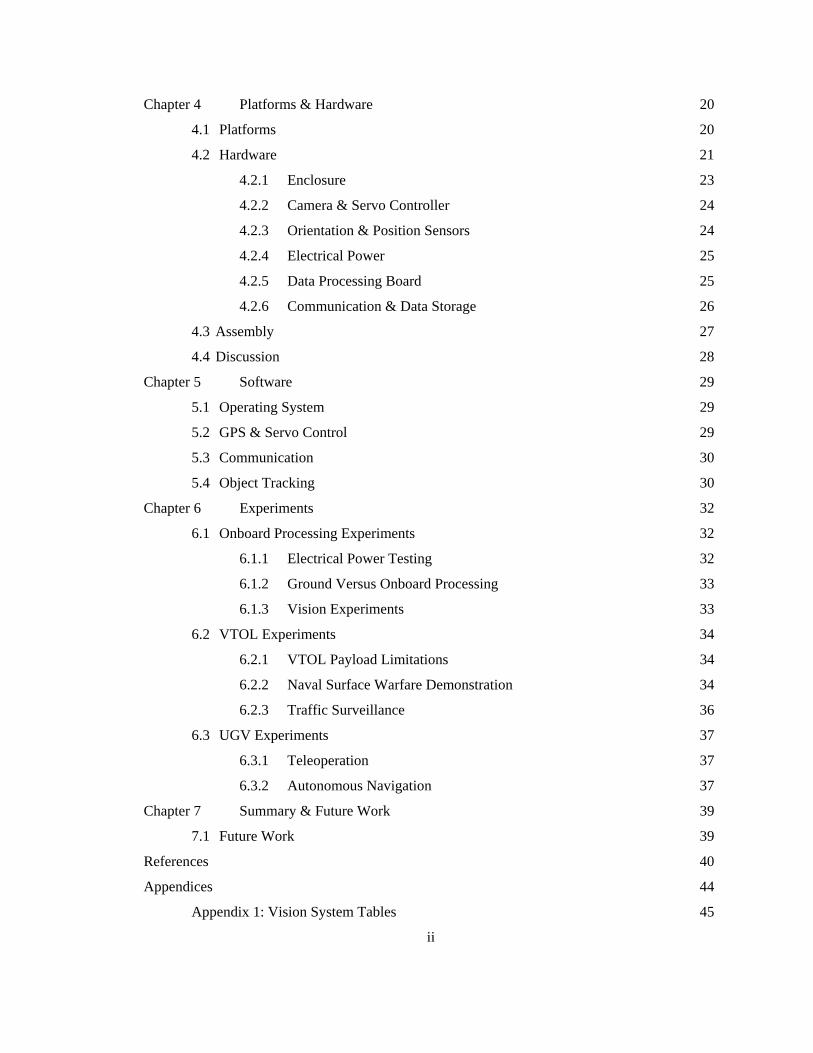
Chapter 4 Platforms & Hardware 20
4.1 Platforms 20
4.2 Hardware 21
4.2.1 Enclosure 23
4.2.2 Camera & Servo Controller 24
4.2.3 Orientation & Position Sensors 24
4.2.4 Electrical Power 25
4.2.5 Data Processing Board 25
4.2.6 Communication & Data Storage 26
4.3 Assembly 27
4.4 Discussion 28
Chapter 5 Software 29
5.1 Operating System 29
5.2 GPS & Servo Control 29
5.3 Communication 30
5.4 Object Tracking 30
Chapter 6 Experiments 32
6.1 Onboard Processing Experiments 32
6.1.1 Electrical Power Testing 32
6.1.2 Ground Versus Onboard Processing 33
6.1.3 Vision Experiments 33
6.2 VTOL Experiments 34
6.2.1 VTOL Payload Limitations 34
6.2.2 Naval Surface Warfare Demonstration 34
6.2.3 Traffic Surveillance 36
6.3 UGV Experiments 37
6.3.1 Teleoperation 37
6.3.2 Autonomous Navigation 37
Chapter 7 Summary & Future Work 39
7.1 Future Work 39
References 40
Appendices 44
Appendix 1: Vision System Tables 45
ii

List of Tables
Table 1: EPIA MII Device Support 26
Table 2: Existing Vision Systems for VTOL Platforms 45
Table 3: Summary of System Characteristics and Functionality 46
iii
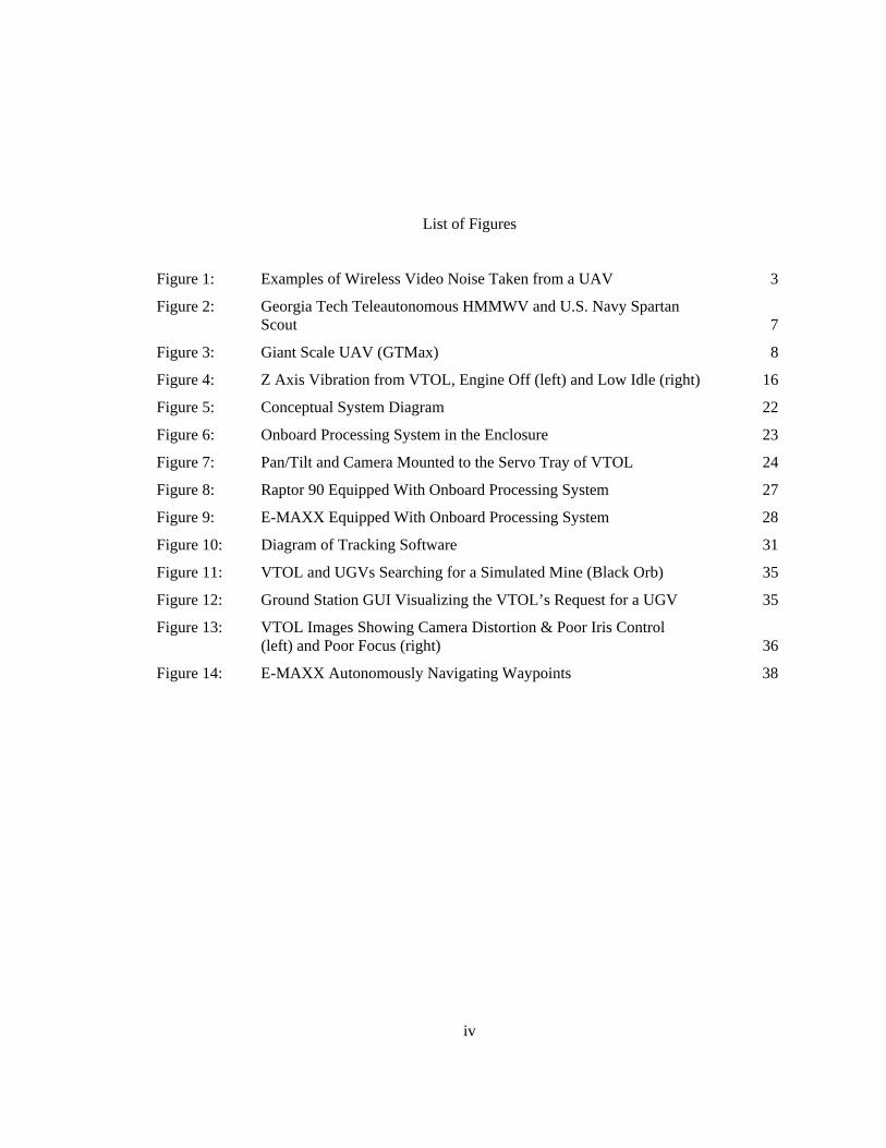
List of Figures
Figure 1: Examples of Wireless Video Noise Taken from a UAV 3
Figure 2: Georgia Tech Teleautonomous HMMWV and U.S. Navy Spartan Scout 7
Figure 3: Giant Scale UAV (GTMax) 8
Figure 4: Z Axis Vibration from VTOL, Engine Off (left) and Low Idle (right) 16
Figure 5: Conceptual System Diagram 22
Figure 6: Onboard Processing System in the Enclosure 23
Figure 7: Pan/Tilt and Camera Mounted to the Servo Tray of VTOL 24
Figure 8: Raptor 90 Equipped With Onboard Processing System 27
Figure 9: E-MAXX Equipped With Onboard Processing System 28
Figure 10: Diagram of Tracking Software 31
Figure 11: VTOL and UGVs Searching for a Simulated Mine (Black Orb) 35
Figure 12: Ground Station GUI Visualizing the VTOL’s Request for a UGV 35
Figure 13: VTOL Images Showing Camera Distortion & Poor Iris Control (left) and Poor Focus (right) 36
Figure 14: E-MAXX Autonomously Navigating Waypoints 38
iv

An Modular Onboard Processing System for
Small Unmanned Vehicles
Richard D. Garcia
ABSTRACT
This work describes the design and implementation of a generic lightweight onboard processing
system for miniature Unmanned Vehicles (UVs) that is computationally powerful and highly
adaptable. First, several classical approaches to giant scale and full size UV onboard processing
systems are described along with their corresponding limitations. Second, a detailed study is
presented that describes the key characteristics of an onboard system along with associated
limitations. Next, an implementation of a generic onboard system capable of vision processing
and servo based control is presented along with detailed hardware specifications and
implementation software. Last, experimental data, both laboratory and field, are presented to
show validation of the onboard processing system design, functionality, and key characteristics
presented.
Two primary contributions are made in this work. i) Identification of key characteristics
of an onboard system allows for a high level validation of the hardware of an onboard system
along with a design template for a reconfigurable, platform independent, processing system for
UVs. ii) Detailed design and implementation of an adaptable onboard processing system that is
both computationally powerful and easily adapted.
This system is validated by showing satisfiability of the design characteristics necessary
for an adaptable onboard system along with fully operational field test and their corresponding
results.
v

Chapter 1
Introduction
1.1 Introduction & Motivation
The goal of this thesis is to provide a high powered onboard system capable of running
online vision algorithms and feedback control from multiple unmanned platforms including
miniature ones. This processing system’s nonspecific nature allows for simple “plug and play” of
the system onto platforms including, but not necessary limited to, both aerial and ground vehicles.
This work is relevant not only to robotics but to any reconnaissance type platform that must be
functional regardless of communication status. This chapter presents both the research question
and the motivation behind the work. The last section of this chapter details the contributions of
this work and outlines the specific areas of this thesis that support these claims.
The research is motivated by the challenge to design, implement, and test an on-board
processing system that is capable of computationally expensive algorithms regardless of ground
station connection yet is nonspecific enough to function on multiple platform vehicles tasked with
very distinct goals. This thesis focuses specifically on miniature ground and aerial vehicles
whose characteristics typically include a small foot print, low endurance, and minimal payload
capacity. Although the focus is on miniature vehicles the validity of the processing system is not
limited to these platforms.
Fundamental issues justifying implementation of an onboard processing system as
opposed to ground station processing are three fold:
• Reduce the overall network traffic
• Increase the quality of data processing
• Increase the vehicles level autonomy
1
1.2 Problem Statement
The problem the thesis addresses is as follows:
Miniature unmanned vehicles are becoming popular due to their compact size, high
maneuverability and high size-to payload ratio. This is especially true with Vertical Takeoff and
Landing (VTOL) vehicles due to their distinct capabilities to maneuver in any direction and to
hover, even in highly confined areas. Efficiency and functionality are the main goals of any
unmanned vehicle. In vehicles specifically designed for quick and easy deployment, it is
imperative that any onboard equipment be as generic and adaptable as possible. This creates an
environment where resources can be stretched further without jeopardizing response time or
effectiveness. This statement has served as the reference point for the proposed onboard
processing system.
Payload is, without question, the most limiting factor in miniature UV platforms. It is
also the main boundary between larger UV platforms and miniature UV platforms. Larger UV
platforms are capable of carrying large generators and sacrificing horse power for electrical
power. This allows onboard system development with very little regard to electrical needs of the
system. This is not the case in miniature UV platforms. Miniature platforms can sacrifice neither
the horsepower nor the payload loss required to generate electrical power. Experiments,
presented in Chapter 6, show realistic payload limitations of approximately 8.5 pounds for a
typical miniature UV platform. This creates major restrictions on the devices that can be placed
on the platform. For these reasons it is typical to see many miniature UVs equipped with only
lightweight cameras and transmitters that convey their information to ground stations. The
transmitted data is then used by ground processing systems to perform all the necessary
computations.
These types of ground processing systems contain a serious bottleneck. The data
transmission via wireless communication channels introduces both noise and data loss [1]. The
transmitted video is commonly littered with static and color rearrangements, as visible in Figure
1. It is also typical to see complete video dropout due to lost communication or bandwidth
limitations. Wireless transmission also entails serious security issues. Transmitted data may be
maliciously damaged or stolen. Software encryption only adds to the computational demands of
the ground processing system and hardware encryption only taxes the already limited payload of
the platform.
2
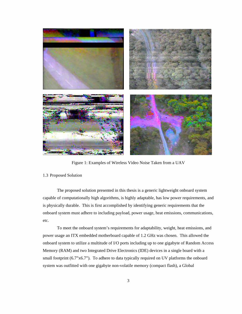
Figure 1: Examples of Wireless Video Noise Taken from a UAV
1.3 Proposed Solution
The proposed solution presented in this thesis is a generic lightweight onboard system
capable of computationally high algorithms, is highly adaptable, has low power requirements, and
is physically durable. This is first accomplished by identifying generic requirements that the
onboard system must adhere to including payload, power usage, heat emissions, communications,
etc.
To meet the onboard system’s requirements for adaptability, weight, heat emissions, and
power usage an ITX embedded motherboard capable of 1.2 GHz was chosen. This allowed the
onboard system to utilize a multitude of I/O ports including up to one gigabyte of Random Access
Memory (RAM) and two Integrated Drive Electronics (IDE) devices in a single board with a
small footprint (6.7”x6.7”). To adhere to data typically required on UV platforms the onboard
system was outfitted with one gigabyte non-volatile memory (compact flash), a Global
3

Positioning System (GPS) receiver, wireless communication (802.11B), a camera (Unibrain Fire-
I), and a Pulse Width Modulation (PWM) controller capable of controlling up to eight distinct
devices.
To further advance the onboard system’s adaptability it was loaded with a highly
developed and adaptable non-graphical operating system (Slackware Linux 10.0 with a 2.4.26
kernel). This allows the onboard system plug and play capabilities and access to commercial and
open source software while requiring less than 100 megabytes of non-volatile memory.
Last, the onboard system is mounted within a shock resistant enclosure that is resilient to
liquid vapors and debris while remaining extremely lightweight. This allows the system
functionality in varying and unknown physical situations without limiting the abilities of the
system.
1.4 Thesis Outline
The remainder of this thesis is organized as follows. Chapter Two provides an overview
of related work along with corresponding limitations, while Chapter Three presents a list of
generic abilities for onboard systems along with justifications. Chapter Four and Five describe, in
detail, the proposed solution including the utilized hardware and software respectively along with
justifications for both. Chapter Six is dedicated to detailed descriptions of performed experiments
including results. Chapter Seven concludes this thesis with a closing discussion and is followed
by References.
4

Chapter 2
Related Work
There is currently great interest in designing on-board easily reconfigurable systems for
miniature UVs. Although miniature on-board systems are a fairly new area of research, there has
been extensive research into full size [37, 33] and giant scale [23, 2] systems, especially in the
area of on-board vision processing [7], see Tables 2 & 3 in the Appendix. Full size and giant
scale UVs correspond to vehicles proportional in size to their manned counterparts and vehicles
that require special permission, typically Federal Aviation Administration (FAA) clearance, to
operate (i.e. >55 lb model aircraft), respectively.
2.1 Full Size Onboard Systems
One example of a full size onboard system is the one present on the Georgia Institute of
Technology’s teleautonomous High Mobility Multi-Purpose Wheeled Vehicle (HMMWV). This
system, developed in 1997 under the guidance of Dr. Ronald Arkin, is capable of semi-
autonomous and teleoperated navigation [5]. The system was developed on a military type 4x4
HMMWV vehicle, as seen in Figure 2, and supported a combination of on-board and off-board
processing.
The Georgia Tech HMMWV was equipped with a GPS receiver, onboard gyro stabilized
Inertial Measurement Unit (IMU), and a radio modem for ground communication. The onboard
system was further equipped with three actuators responsible for controlling steering, braking,
and throttle. The onboard system is completed with two PC-104 stacks responsible for low level
control of the actuators, communication, and heading determination. The entire system is
powered by the HMMWV’s standard alternator which is inverted to 110 Volts Alternating
Current (VAC).
Although this design allows a remote operator to successfully navigate the Unmanned
Ground Vehicle (UGV) to a determined location, it is not without faults. The most serious issue
with this type of onboard system is its design around a large non-commercial platform. The
5
system utilizes large actuators that are designed to run off of the platform’s standard battery
supply, 24V [5]. This onboard system would require redesign of the actuator equipment to be
implemented on the majority of commercial vehicles which operate at half the voltage and
amperage as the HMMWV. This design also requires communication to be present at all times to
function correctly. This is due to the design’s partial control and processing from an off-board
system.
More current full size onboard systems in development include the Spartan Scout
Unmanned Surface Vehicle as seen in Figure 2. The Spartan is a rigid hull inflatable boat capable
of semi-autonomous control. It varies around 7 meters in length and is capable of carrying
payloads up to 3,200 lbs at ranges up to 14 miles for 3 hours [37, 28]. The Spartan Scout is
controlled via a Graphical User Interface (GUI) from a nearby parent vessel.
The basic onboard equipment contained on the Spartan Scout is an electro-
optical/infrared surveillance turret, surface radar, digital imagery transmission system, and an
unmanned command and control system [30]. This equipment is standard on all Spartan vehicles
and allows the onboard system a concrete base of hardware to work with. This vessel is designed
to integrate a multitude of modular pods allowing the platform to be quickly and easily
customized for a specific task. The Spartan’s modular pods include devices for Reconnaissance,
Surveillance, and Target Acquisition (RSTA), Precision Strike (PS), Anti-Surface Warfare
(ASuW), Force Protection (FP), and littoral Mine Warfare (MIW) [19].
Although the Spartan allows large manned naval vessels to extend the range of their
sensors and counter enemy attacks with minimal risk, it does come at a price: approximately $30
million United States Dollars (USD) for the development of four prototypes [37]. This price tag
presents a serious limitation in the non-military areas of research. This onboard system is also
not well designed to function on smaller UVs due to system’s use of a large environmentally
enclosed surveillance turret and surface radar which are both physically large and typically have
high power consumption.
6

Figure 2: Georgia Tech Teleautonomous HMMWV and U.S. Navy Spartan Scout
2.2 Giant Scale Onboard Systems
One example of a giant scale onboard system is the one present on the Mobile Detection
Assessment Response System – Exterior (MDARS-E). This is a jeep style platform that is
designed to fit within the bed of a large commercial truck or the back of a HMMVW. It was
designed to complete security tasks, intruder detection, and respond to alarms and is a joint
Army-Navy development effort [35]. It is built around a four wheel frame which utilizes an all-
terrain suspension, hydraulic steering and is capable of speeds up to 40 Mph [36].
The MDARS-E is equipped to navigate outdoor terrain by use of differential GPS and
vehicle dead reckoning which are fused during movement to provide an accurate position. The
onboard system is also capable of obstacle avoidance through the use of four types of onboard
sensors: millimeter wave radar, stereo vision range finders, a single point scanning laser, and
multiple ultrasonic sensors. Intrusion detection is accomplished using a narrow Field of View
(FOV) radar, Forward-Looking Infrared (FLIR), and passive infrared sensors all mounted to a
turret capable of 360º of movement [34].
The MDARS-E’s hardware paired with advanced vision recognition software and
communications allows for a very robust autonomous, semi-autonomous, and teleopterated
vehicle. One distinct disadvantage of this type of design is cost which can exceed $500,000
USD. A second limitation to the MDARS-E UV is power consumption. The functionality of the
vehicle relies on multiple panning and tilting units that utilize several active sensors including
7

radar, laser, and ultra sonic. These types of sensors are also typically heavy in weight and have a
high power consumption rate.
Giant scale aircraft have also proven to be extremely effective platforms for on-board
processing systems. One particularly notable platform is the Yamaha RMAX. This platform
consists of a 2-stroke horizontally opposed 246cc engine mounted to a 3.63 m long frame [29].
The platform has a payload capacity of approximately 28 kg which allows it to accommodate
very large onboard systems containing multiple cameras, a radar altimeter, and complete desktop
size computer [17]. The most notable usage of the Yamaha RMAX is Georgia Tech’s GMAX.
Georgia Tech’s Software Enabled Control (SEC) has used the RMAX platform along
with a custom developed onboard system to assist in high performance autonomous control of the
unmanned aerial vehicle (UAV) VTOL, see Figure 3. Georgia Tech’s onboard system consist of
a NovAtel RT-2 GPS receiver, sonar altimeter, HMR-2300 Magnetometer, ISIS-IMU, Radar
Altimeter, two onboard computers, and an Aironet MC4800 wireless data unit [17]. The entire
onboard system is powered by the RMAX’s onboard generator and control of the helicopter is
handled by both Georgia Tech’s onboard system and the Yamaha Attitude Control System
(YACS) present on all standard RMAX vehicles.
Figure 3: Giant Scale UAV (GTMax)
The GT-MAX with its high payload capabilities, extensive sensor suites, auto
stabilization, flight guidance software, and long endurance rank it as one of they top autonomous
UAV VTOL’s in the world. Although the system is highly advanced and developed it is not
without issues. First, the RMAX platform is nine feet long from tail to nose without the blades
attached and weighs in at approximately 140 lbs. The shear size and weight of the vehicle and
8

hardware limits its transportation to oversized ground freight and specialized air transport. This
makes efficient deployment of this type of vehicle very difficult. Second, the RMAX platform
with the GPS option and a 100 meter flight ceiling has a price tag of approximately $240,000
USD. This is without the custom flight control system, IMU, ground radar, vision system, and
support equipment. Last, the RMAX platform does not contain an autorotation clutch. This
device, installed on all modern full-size VTOL aircraft, allows the platform to maneuver in the
event of an engine failure. It is fairly trivial for a trained pilot to safely fly and land a VTOL
vehicle containing an autorotation clutch that has had engine failure. This is a serious safety issue
and should be considered when utilizing a VTOL vehicle without an autorotation clutch.
2.3 Midsize Onboard Systems
Midsize UVs are the most common and frequently used unmanned platforms today.
Midsize vehicles are capable of long run times, reasonable payload capacities, and somewhat
simplified storage and deployment. Above all, midsize platforms are popular due to their
relatively inexpensive cost ranging from several thousand dollars to a few hundred thousand.
This is mainly due to the platforms ability to function using highly manufactured parts that do not
require modification for size, weight and power consumption.
Although onboard processing for midsize UGVs is a fairly well researched area there has
recently been a great deal of interest in on-board processing for midsized UAVs. Most notable
among these size platforms is USC’s Autonomous Vehicle Aerial Tracking and Reconnaissance
(AVATAR) vehicle which incorporates three firewire cameras, two IMUs, two PC-104 stacks (a
stack of 5 and 6), two wireless transmitters, two solid state drives, and two power supplies [38].
This onboard system is mounted on a Bergen Industrial Twin helicopter utilizing a 46cc twin
cylinder two cycle engine with a 10 kg payload capacity.
The AVATAR vehicle has been shown to be effective in both autonomous flight and
visual identification of objects [21]. The AVATAR has also combined its visual recognition
abilities with its flight capabilities to perform vision assisted flight. This ability has been used to
accomplish vision based autonomous landings and the tracking of objects of interest. The
AVATAR has also been used in the deployment of marsupial robots and the autonomous
deployment and repair of sensor networks [10].
AVATAR, like its giant scale counterparts, is still plagued with deployment and storage
issues. The stock Industrial Twin platform is almost 5 feet long and 2 feet high without blades or
9

modified skids. This limits this design to freight and specialized air transport making fast
deployment very difficult and expensive. Another drawback to the AVATAR onboard system is
its development around 11 PC-104 boards in two stacks. This type of configuration forces the
onboard system into rectangular masses. This design’s hardware choices limit the mounting
capability of the onboard system which, on aerial vehicles, is typically already limited by flight
characteristics of the platform. This also imposes serious problems when one considering moving
the setup to another platform.
2.4 Adaptable Onboard Systems
There has also been considerable research into the area of “plug and play” sensor suites
that connect to highly adaptable onboard systems [20]. These adaptable onboard systems allow
sensor suites, typically referred to as sensor/module pods, which are typically highly specialized,
to easily interface with the onboard system and vehicle platform. These modular pods are present
on a multitude of vehicles including the previously mentioned SPARTAN Scout. They are
typically low profile devices utilizing universal mounts for sensor pods that, in aircraft, are
typically mounted directly below the fuselage and transmit information to the onboard system
and/or ground station. These complex and highly developed devices allow a single platform to
function for multiple tasks with only the replacement of a single pod required.
2.5 Summary
Although prior research has shown the enormous benefits of onboard processing systems
specifically to highly adaptable and highly mobile platforms, the migration of these systems to
small highly agile platforms has yet to be fully explored. To effectively utilize the many benefits
of miniature UVs, onboard processing, comparable to those of larger platforms, must be
developed.
10
Chapter 3
Onboard System Development
Although the idea of onboard system processing for miniature UVs appears to be a fairly
straight forward design and implementation process, it does have several unforeseen pitfalls that
must be explored before an effective and efficient design can be accomplished. First, a designer
of an adaptable onboard system must identify generic abilities that are very typical to the
functional areas of the system. The designer must then consider the limitations of the platforms
and hardware, including issues related to payload limitations, platform propulsion, platform
limitations, operating environment, system power, and safety, all of which increase the
complexity of onboard system design. Specific details of the hardware utilized in validation of
this system are described in Chapter 4.
3.1 Generic Abilities
Adaptable systems must be generic enough to allow for functionality over a large domain
but refrain from forcing the user into using hardware that may be un-useful or even hazardous to
a task. To accomplish this, one must first identify and research the area of functionality of the
adaptable system. In the case of UV’s one must familiarize themselves with known UV
platforms and the type of tasks they are required to perform and identify common aspects of these
tasks.
3.1.1 Position
Positional awareness is one of the most important aspects that a UV must handle.
Whether a UV is designed for indoor and/or outdoor environments it must have some idea of its
position with respect to its environment. This can be accomplished in many ways some of which
include, landmark based localization, dead reckoning, integration of velocity or acceleration, and
11

GPS. Although each method has its benefits they all attempt to accurately calculate the current,
past, and future positions of a UV.
Of all the methods for calculating position GPS is the most widely utilized. It allows a
UV positional data in three dimensions with reference to the earth’s coordinate system. This
allows for robust and precise positional accuracy in most of the world. Although GPS is fairly
robust it does have several issues, it cannot function indoors without use of specially placed GPS
repeaters and it must have a fairly unobstructed view of the sky for accurate position calculation.
Positional data via GPS can even be corrupted by heavy cloud cover. Although GPS does have
flaws it continues to be the most widely used method for outdoor position calculation.
For robustness, an adaptable system must also be able to function in areas where GPS is
not a realistic option: indoor environments and near buildings or large obstacles. This is the
rational for vision based localization, dead reckoning, and integration of velocity or acceleration
which gives position with respect to the UV. Although these techniques are fairly inadequate by
themselves combinations of them have proven to be very effective [11].
To allow for positional accuracy both indoors and outdoors it was decided that the
onboard processing system be equipped with both vision and GPS capabilities. For both the
above reasons and reasoning to be mentioned in the following sections it was determined that the
adaptable system be equipped with accelerometers on 3 axes. These three sensors allow the
system to function outdoors with positional accuracy provided by GPS, indoors with positional
accuracy provided by both the camera and accelerometers, and in transitions from both outdoor
and indoor provided by all three sensors.
3.1.2 Orientation
Orientation also plays a vital role in most UV designs. Position can provide information
about the current state of the UV but is insufficient when the vehicle attempts to transition to a
new position. Typical platforms such as fixed wing planes, VTOLs, Ackermann and skid
steering vehicles all require heading (yaw) to transition from a current position to a desired
position. It is also imperative that UVs be able to accurately determine their roll and pitch
position. This information is used to maneuver typical UAVs and is used for safety on most
UGVs.
Orientation can be sensed by electron sensors or calculated based on passed information.
Typically, calculation of orientation is limited to heading. This is usually accomplished by
12

commanding a known movement, i.e. straight forward, and then using the previous and current
position to calculate heading. This type of calculation can be very accurate if position
information is very accurate or the calculation is performed over a large movement. Sensed
orientation is typically accomplished via magnetrometers which provide magnetic force readings
on multiple axes. These readings use the magnetic field produced by the earth to determine roll,
pitch, and yaw. These reading are heavily influenced by magnetic fields produced by other
objects including ferrous metals and electrical current. In dynamic systems these disturbances are
typically filtered using gyroscopic readings on parallel axes.
For these reasons it was determined that this processing system be equipped with 3 axis
magnetometers and gyroscopes. This would provide adequate orientation information about the
state of both UGVs and UAVs.
3.1.3 Movement
Movement, although obvious, is crucial to any UV design. To be functional, a UV must
have the ability to orient itself or a part of itself. This could be as simple as the movement of a
pan/tilt system or as complex as 3D flight from a VTOL vehicle. Although there are extreme
differences between the two previous examples they both contain one fundamental similarity:
they both control the position of an actuator or multiple actuators.
Examples of actuators include electric motors, thermal bimorphs, hydraulic pistons,
relays, piezoelectric actuators, comb drives, and electroactive polymers. All of which transform
some type of input signal into motion. In UV designs, this input signal is typically an electical
signal indicating the position and/or speed of the actuator.
This need to precisly control the movement of some ascpect of the UV led to the
integration of a servo controller into the processing system. The servo controller was chosen
based on the fact that most miniature platforms are controlled via small servo motors. In the
event that desired actuator is not a servo the PWM signal produced by the servo controller can be
converted to supply the correct input syntax.
13
3.1.4 Process Data
All of the above abilities are fairly useless without some level of data processing.
Whether the processing is accomplished at a local ground station or on the UV the data must be
processed. This type of processing can be accomplished by small integrated hardware with
minimal adaptability to massive multiprocessing machines. Processing systems range greatly in
size, power consumption, heat dissipation, computational ability, and peripheral support.
Examples of processing boards include Basic stamp, PC-104, Advanced Technology Extended
(ATX), ITX, and custom microprocessor designs. These boards allow for a multitude of input
and outputs via various ports and support several levels of operating systems and peripheral
devices.
When selecting a processing board one must first consider the location at which the
processing system will be stored. Processing accomplished at a local ground station has the
advantage of almost limitless computational and electrical power. Although this is very inviting
the environment in which UVs typically operate (over long distances and typically not line of
sight) and the medium by which they transfer data (802.11, serial modem, etc) is severely limiting
(discussed in detail in the following section).. For this reason it was decided that the processing
board for this adaptable system be located on the UV.
3.2 Limitations
When designing an adaptable onboard processing system one must pay a great deal of
attention to the limitations of both the platforms on which the system could be used and the
environment in which the system could be used. This includes issues related to payload,
propulsion, platform limitations, operating environment, and electrical power, all of which will
add to the overall complexity of the onboard design.
3.2.1 Payload
Payload limitation is by far the most important limiting factors in miniature UVs. Such
limitation requires the sacrifice of larger highly accurate sensors with smaller lighter less accurate
sensors. It also limits the use of onboard equipment with high power consumption rates including
high power processors, lasers range finders, radars, etc. This is mainly due to the majority of
14
platforms needing to carry all of the power required to operate the onboard system and platform.
This requirement creates an unforeseen payload decrease with every new piece of hardware. The
designer is forced consider both the actual weight of any hardware added to the onboard system
and the weight of the extra power required to properly operate the hardware.
The limitation imposed on the size and weight of hardware added to any onboard system
is always a tradeoff between the hardware’s ability and the overall dimensions and weight. A
designer must consider that any reduction in the ability of the hardware will most likely have to
be overcome through software. The designer should also be aware that extra strain placed on
software may cause currently working software and hardware to fail.
Payload is also crucial when focusing on the dynamics and safety of a UV. Even
payloads that fall under the maximum abilities of the vehicle may still create unforeseen
complications. First, any increase to the total weight of the vehicle will affect the overall
dynamics of the vehicle. This alteration could be either positive or negative depending on the
hardware and platform. For example, a well placed weight on a UGV platform may lower the
center of gravity decreasing the possibility of a roll over or even decrease the overall vibration of
the vehicle. It is also possible that this same weight could lower the ground clearance of the
vehicle increasing the possibility of the vehicle becoming high centered. Second, incorrectly
placed payload can severely alter the vehicle’s dynamics and cause serious safety issues. For
example, a seemingly small payload placed too far out on a fixed wing aircraft could cause the
wing to break under high wind or could cripple the ailerons in a side wind.
3.2.2 Propulsion
When designing an onboard system one must consider the limitation imposed by the
propulsion of the platforms that will be utilized. In the area of miniature UV platforms the types
of propulsion are typically limited to jet, electric, methanol, and gas. Each has it limitations for
overall UV performance but the discussion will be limited to the limitations that affect the design
of the onboard processing system.
Although electrical, methanol, gas, and jet propulsion systems are very different they will
each have some effect on any nearby or direct mounted object. For electrical propulsion this
includes large magnetic fields. These are typical in platforms that can use well over 20 amps of
current. These spikes can have adverse effects on unshielded wires or any sensors that rely on
magnetic fields for accurate measurements (i.e. electronic compasses). Methanol and gas
15

propulsion systems typically expel a large amount of unburned oil and gas. This can be very
hazardous to any electronics that are not environmentally protected. Last, jet propulsion exposes
its surroundings to a great deal of heat and noise. This could cause damage to sensitive sensors or
hardware placed near the engine.
3.2.3 Platforms
All UV platforms have some type of limitation. Limitations may greatly cripple the
functionality and safety of the UV if they are not handled with care. Limiting factors in miniature
UV’s include vibrations, freedom of movement, control difficulties, payload limitations, and
safety.
Vibrations are a very serious issue when designing an onboard system. This is mainly
due to the sensor noise caused by vibration. Many UV platforms rely on rates and accelerations,
provided by gyroscopes and accelerometers, for accurate vehicle functionality. One example of
the severity of this noise is visible in Figure 4, where the level of noise from a static object is
approximately 0.015 Gs compared to an object hard mounted to an engine in low ideal which is
approximately 0.6 Gs. This is 40 times the amount of noise in a static object. The level of
severity is highly dependent on the mounting method, platform type, and propulsion type.
Figure 4: Z Axis Vibration from VTOL, Engine Off (left) and Low Idle (right)
Vibration is also an issue with the physical stability of the onboard system. Many
electronic parts are built around the assumption that they will be used in a semi-static
environment. When these types of electronics are placed in high vibration and shock
16

environments their probability of failure increases greatly. Great care must be taken to assure that
the capabilities of the hardware are not exceeded. This can be accomplished by using
components specifically designed for high vibration environments or by reducing the amount of
vibration felt by that component. This can be done using vibration reducing mounts in key areas.
Great care must be taken to ensure that vibration reduction material does not cause amplification
of vibration due to the frequency of the vibration.
Freedom of movement and control difficulties are also a concern when dealing with UV
platforms. This is apparent when one considers the extreme differences in control, even
teleoperation, when dealing with 2 axis operating vehicles (UGVs) and 3 axis operating vehicles
(UAVs). The main issues being the need to accurately and quickly determine the position,
orientation and rates in three dimensions rather than two dimensions. This can have a multitude
of effects on the vehicle. For example, consider what must be controlled when moving a UV
forward. A UGV with Ackermann steering must assure that its turn angle is zero (steering
control) and must have some forward rotation on the tires (acceleration control). A UAV VTOL
must assure that the vehicle does not loose altitude (collective control), that its main rotor turns
(throttle control), that it does not roll to either side (aileron control), that it does not yaw left or
right (heading control), and that it has some forward motion (pitch control).
Safety, although not entirely obvious, should be the most important of all concerns when
dealing with any UV. All UV’s are dangerous when not given the proper care and attention they
demand. Typical UVs, even miniature ones, are large enough to damage property and causes
severe injuries. This can be limited to cuts and bruises caused by a run away UGV or the death of
college caused by a VTOL’s main blades. One must design onboard processing systems that do
not disturb the natural safety precautions on the utilized platform and account for any safety
issues that the onboard system may impose on the UV. This could include switches that shut
down components in the event of failure, teleoperation takeover, or even redundant components.
3.2.4 Environment
The environment in which a processing system functions has a great effect on the design
of any processing system. This effect is typically limited to the type of enclosure in which the
onboard system is contained but can also reflect directly on the hardware itself. Specifically,
hardware designed for a particular environment can alleviate constraints on the enclosure and
17

improve overall system’s performance. This could include industrial designed hardware which is
typically more tolerant of heat variations, moisture, and radiation.
Although some hardware may reduce constraints on the enclosure they are typically
expensive and may go far beyond the requirements of the UV’s operation. In these instances
special attention should be taken to ensure that the enclosure can support all of the required
operating environments. This includes environments that are exposed to chemicals, extreme heat
and cold, radiation, moisture, pressure, etc. One must also assure that enclosure constraints do
not directly conflict with onboard system’s functionality. For example, an air tight enclosure will
loose the ability to measure barometric pressure which is commonly used to measure altitude.
One must even consider the type of material from which the enclosure is made. Materials that do
not conduct heat will increase the overall temperature of the enclosed hardware, ferrous metals
will have adverse effects on electric compasses, and some materials are too soft or rigid for a
particular design.
3.2.5 Electrical Power
Power is a very limiting factor in any hardware design but especially limiting in
miniature unmanned vehicles where payloads are highly limited. Most UVs require that all
electrical power be carried onboard the platform. This requirement puts a great stain on the
designer to assure that each piece of hardware is absolutely necessary and power efficient. It also
forces the designer to consider power sources that have high power to weight ratios. Examples of
such power sources would be lithium batteries (polymer and ion) and onboard generators.
Lithium polymer and ion batteries allow hardware to utilize power that is low in weight,
high in power output, and rechargeable. Lithium batteries have a great advantage over Nickel
Metal Hydride and Nickel Cadmium batteries due to there three and four times higher power to
weight ratio respectively [27]. Although lithium batteries are very appealing to onboard system
design, it does come at a price. Lithium batteries have very sensitive discharge and recharge
ratios and are very sensitive to shock. Incorrect care for these batteries can easily result in
explosions and fire.
It is also appealing to allow a platform to supply its own electrical power via an onboard
generator. Although this choice would seem optimal it does require several sacrifices. First, an
onboard generator adds weight to the design pulling from an already taxed payload. Second, the
18

power required to operate the generator is equal to or greater than power output by the generator.
For example, a gasoline powered platform will use extra combustion to produce electrical power.
This will increase the amount of fuel spent at any given time. Basically, an electrical generator
will reduce to overall platform endurance.
19

Chapter 4
Platforms & Hardware
Hardware is the building block of all unmanned vehicles. Decisions made about
hardware can significantly decrease or increase the complexity and functionality of an unmanned
system. For this reason great effort is taken to effectively describe and justify the chosen
hardware.
4.1 Platforms
The utilized UAV platform is a Raptor 90 SE VTOL with the following characteristics:
• Manufacturer: Thunder Tiger
• Rotor Diameter: 710 mm (Symmetrical)
• Dry Weight: 5.8 kg
• Dimensions: 130x27x48cm (w/o Blades)
• Payload Capacity: 4 kg
• Endurance: 18 min
• Battery: 4.8 V (2.6A) NiCad
• Fuel: 30% Nitrous (Methanol)
• Engine: OS 0.91 C-Spec
This platform was chosen due to its high power output and small size. The platform has
been shown to have relatively low vibration and an ability to handle wind gust exceeding 15 mph.
The utilized UGV platform is an E-MAXX RC truck with the following characteristics:
• Manufacturer: Traxxas Corporation
• Max Speed: 30 Mph
• Drive system: Shaft-drive 4WD
• Dry Weight: 3.8 kg
20
• Dimensions: 49x41x27cm
• Endurance: 40 min
• Battery: Dual: 7.2V 8Ah LiPo
• Motor: Dual Titan™ 550
• Speed Controller: EVX FWD/REV electronic
This platform was chosen due to its rugged nature, wide wheel base, adjustable
suspensions system, and low center of gravity.
4.2 Hardware
The hardware components of the onboard system consist of:
• 1.2 GHz EPIA Processor
• Via Embedded motherboard
• Unibrain Firewire Camera
• Microstrain 3DM-G IMU
• 1 Gig 266 MHz RAM
• 1 Gig Compact Flash
• Compact Flash to IDE adapter
• Motorola M12+ GPS Receiver
• 8 Channel Servo Controller
• 200 W Power Supply
• 11.1 V LiPo Battery
• 802.11B Cardbus
This configuration was chosen because of its high computational capabilities, various
Input/Output (I/O) ports, size, low heat emission, and cost. Figure 5 depicts the overall concept
for the onboard processing system as well as connection descriptions.
21

Figure 5: Conceptual System Diagram
22

4.2.1 Enclosure
The onboard processing system is packaged into a 32x19x5 cm basswood box mounted
on a lightweight aluminum sheet, see Figure 6. This sheet is mounted directly to the VTOL’s
skids via rubber insulated pipe clamps or to the UGV by rubber insulated aluminum sheets. The
slim design of the enclosure allows for mounting of the hardware without modification to the
standard carbon fiber skids of the VTOL and allows for a lower center of gravity on the UGV.
The box is coated with a gas proof heat shrunk plastic typically used to coat model airplanes.
Basswood was chosen for the enclosure due to its lightweight nature and its lack of electrical
conductance.
Figure 6: Onboard Processing System in the Enclosure
23
Servo Controller
Compact Flash & Adapter
GPS Receiver
Power Supply
802.11 Card
Motherboard

4.2.2 Camera & Servo Controller
For the VTOL platform, the camera was shock mounted directly to a Lynxmotion pan/tilt
unit, Figure 7. This unit was, in turn, hard mounted directly to the underside of the Raptor’s
servo tray. The pan/tilt system consists of two Futaba S3004 servos that are interconnected by
1/3cm laser cut Lexan. This setup allows the camera to pan and tilt up to 90o Servo commands
are issued by the eight channel servo control board located within the enclosure.
For the UGV platform, the camera was hard mounted to the front bumper of the vehicle
and panning motions were assumed to be controlled by the direction of the vehicle.
To fully utilize the potential of the onboard system for the UGV the servo controller was
directly connected to the speed controller and steering servo of the vehicle. This modification
allows the entire movement of the platform to be controlled via the onboard processing system.
Details of this implementation are discussed in chapter Five. This type of implementation was
not considered an option on the VTOL platform due to safety concerns associated with the
possibility of uncontrolled movements.
Figure 7: Pan/Tilt and Camera Mounted to the Servo Tray of VTOL
4.2.3 Orientation & Position Sensors
To satisfy the need for orientation data required by many software algorithms [31] a
Microstrain 3-DMG was mounted to the UV. This device allows the onboard system access to
the current orientation of the platform at up to 100Hz. The sensor is capable of sending both raw
and gyro stabilized data and can supply the processing system with Euler angles, Quaternion
vectors, roll rates, accelerations, and magnetic direction.
24

The onboard system is designed to receive GPS coordinates via the Motorola M12+ GPS
receiver located within the enclosure and the active antenna mounted to either the horizontal fin
of the VTOL or the top of the enclosure for the UGV. The horizontal fin is covered in an
aluminum tape to assist in reception.
4.2.4 Electrical Power
Power for the onboard system is supplied via the 11.1V 4Ah Lithium Polymer (LiPo)
battery mounted on the lower front section of the boom for the VTOL and the undercarriage of
the UGV. LiPo’s were selected based on their high amperage, low weight, and small packaging.
Power distribution to the hardware components is controlled by the 200 Watt ATX power supply.
The power supply plugs directly into the motherboard allowing the unit to add nothing to the
physical dimensions of the hardware.
4.2.5 Data Processing Board
The median for all peripherals of the onboard system is an EPIA VIA M2 motherboard.
This 1.2GHz ITX motherboard provides multiple I/O interfaces, RAM, and CPU on a single
board. The most commonly used I/O interfaces along with the interface type and number
available on the board are described in Table 1. The ITX board has distinct advantages over
typical PC-104 boards that require separate boards for processor, ram, interfaces, etc. Another
drawback to the PC104 form factor is its difficulty in keeping the standard current. The PC104
standard uses a 16 bit ISA bus operating at 33 MHz. This is technologically inferior to the
standard PCI and PCI-X system buses with a 32-bit standard operating at 66 and 133 MHz,
respectively. The ITX motherboard also allows for a multitude of sensor suites and I/O devices to
be added and removed from the onboard system with virtually no modification to the overall
design due to low level integration of I/O ports. The ITX form motherboard also allows for an
extremely thin designed enclosure where PC-104 boards are typically limited to a stack type
configuration.
25
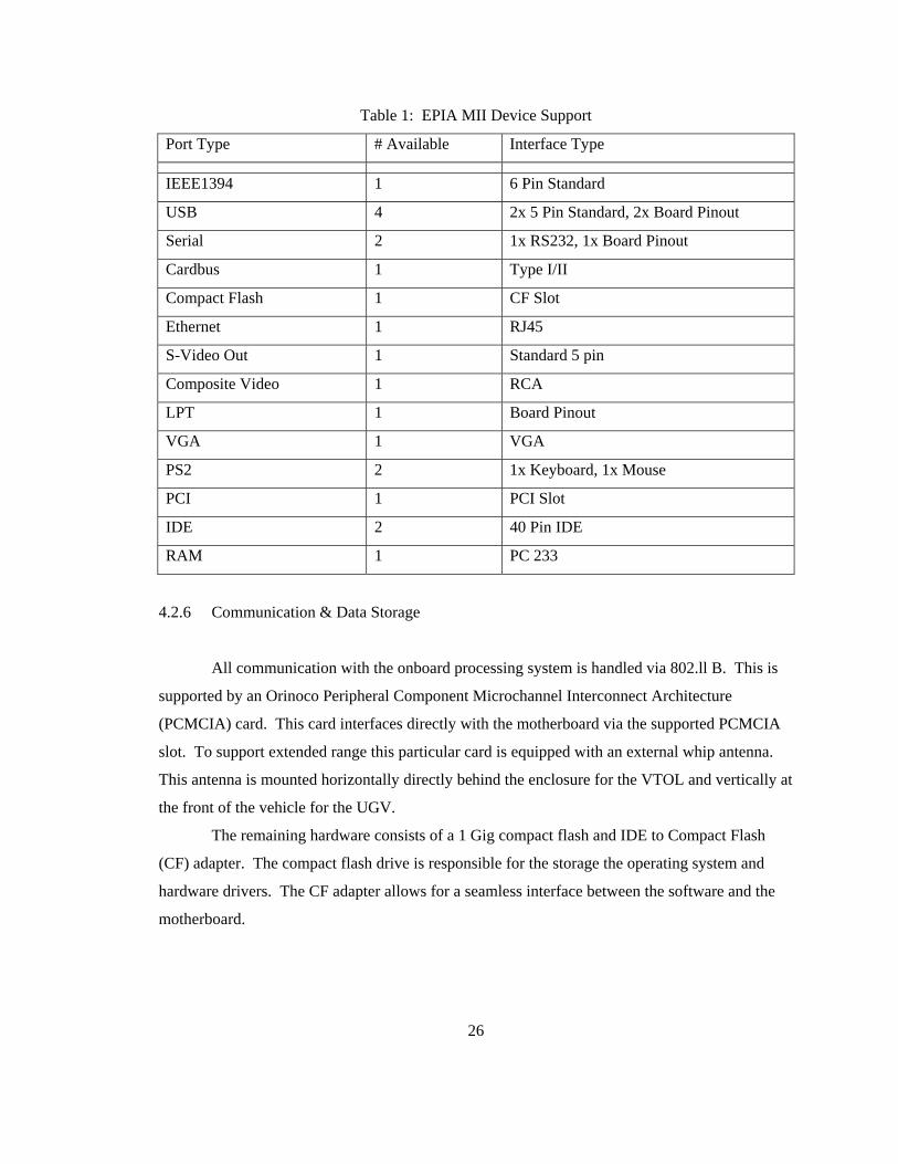
Table 1: EPIA MII Device Support
Port Type # Available Interface Type
IEEE1394 1 6 Pin Standard
USB 4 2x 5 Pin Standard, 2x Board Pinout
Serial 2 1x RS232, 1x Board Pinout
Cardbus 1 Type I/II
Compact Flash 1 CF Slot
Ethernet 1 RJ45
S-Video Out 1 Standard 5 pin
Composite Video 1 RCA
LPT 1 Board Pinout
VGA 1 VGA
PS2 2 1x Keyboard, 1x Mouse
PCI 1 PCI Slot
IDE 2 40 Pin IDE
RAM 1 PC 233
4.2.6 Communication & Data Storage
All communication with the onboard processing system is handled via 802.ll B. This is
supported by an Orinoco Peripheral Component Microchannel Interconnect Architecture
(PCMCIA) card. This card interfaces directly with the motherboard via the supported PCMCIA
slot. To support extended range this particular card is equipped with an external whip antenna.
This antenna is mounted horizontally directly behind the enclosure for the VTOL and vertically at
the front of the vehicle for the UGV.
The remaining hardware consists of a 1 Gig compact flash and IDE to Compact Flash
(CF) adapter. The compact flash drive is responsible for the storage the operating system and
hardware drivers. The CF adapter allows for a seamless interface between the software and the
motherboard.
26
4.3 Assembly
Due to the sensitive dynamics of VTOL aircraft, special attention was taken to select and
assemble all hardware. VTOL roll and pitch movement is typically directed around the Center of
Gravity (CG) [8]. This center of gravity is typically designed to reside on the main shaft of the
platform approximately half way down the frame. This centrally located CG allows the
helicopter to perform highly aggressive maneuvers in very confined areas.
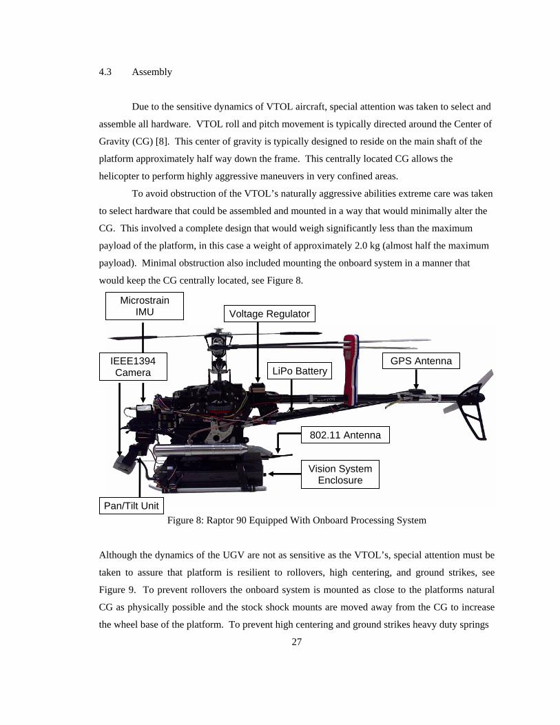
To avoid obstruction of the VTOL’s naturally aggressive abilities extreme care was taken
to select hardware that could be assembled and mounted in a way that would minimally alter the
CG. This involved a complete design that would weigh significantly less than the maximum
payload of the platform, in this case a weight of approximately 2.0 kg (almost half the maximum
payload). Minimal obstruction also included mounting the onboard system in a manner that
would keep the CG centrally located, see Figure 8.
Figure 8: Raptor 90 Equipped With Onboard Processing System
Although the dynamics of the UGV are not as sensitive as the VTOL’s, special attention must be
taken to assure that platform is resilient to rollovers, high centering, and ground strikes, see
Figure 9. To prevent rollovers the onboard system is mounted as close to the platforms natural
CG as physically possible and the stock shock mounts are moved away from the CG to increase
the wheel base of the platform. To prevent high centering and ground strikes heavy duty springs
27
Vision System Enclosure
802.11 Antenna
GPS Antenna
Voltage Regulator
LiPo BatteryIEEE1394 Camera
Pan/Tilt Unit
Microstrain IMU

were added to the suspension system. This forces the shocks to become stiff causing the
suspension system to react more aggressively to vertical forces.
Figure 9: E-MAXX Equipped With Onboard Processing System
4.4 Discussion
It is noteworthy to mention that the abilities of this processing system are highly
unutilized. The capabilities of the processing system can extend to fully autonomous control of a
multitude of UV platforms. The hardware for this processing system is also highly
reconfigurable due to the large number of varying I/O ports and high processing capabilities.
This processing system could be easily configured for obstacle avoidance, infrared sensing, and a
multitude of other tasks.
28
Chapter 5
Software
5.1 Operating System
To select the operating system for the onboard system, several key requirements were
identified like the IEEE 1394 and PCMCIA device support as well as installations that require
less than 500 megabytes. These requirements were based on the need to support the Unibrain
Firewire camera, Orinoco PCMCIA card, and the desire to have an installation that was less than
half the size of the available RAM. Although the first two requirements are straight forward the
third one does require further explanation.
Compact Flash cards are solid state storage that deteriorates with every write to the
device. This becomes a considerable issue when one considers the number of writes made to
permanent storage by the operating system. For this reason it was decided that the compact flash
drive would only be used to load the operating system into memory. From that point all
operations of the operating system would be performed in RAM. To allow the operating system
to have a sufficient work area after being loaded into RAM the operating system had to be
sufficiently smaller than the available RAM (1 Gig).
For the above reasons the Slackware 10.0 installation of Linux was chosen. This
installation provides support for both PCMCIA and IEEE 1394 devices via its 2.4.26 kernel. The
Slackware installation also provides support for low level customization during installation.
Specifically, it provided the ability to remove all graphical content from the operating system
allowing for a very small installation, less than 150 Megabytes compressed. Printer and sound
drivers were also removed to bring the complete installation to approximately 92 Megabytes
compressed.
5.2 GPS & Servo Control
Software for the onboard system’s GPS receiver included a single serial communication
program with the ability to efficiently parse the serial messages. This was accomplished using
29

the National Marine Electronics Association (NMEA) protocol adopted by all current GPS
receivers. This allows the onboard system to remain robust for future hardware updates. The
receiver also supports a faster Motorola specific protocol that was deemed unnecessary for our
requirements.
Servo control software was written to allow both camera movement via the pan/tilt
mounted to the VTOL and autonomous control of the UGV. This is accomplished by passing a
character string, via serial communication, to the servo control board. The character string
corresponded to one of 255 possible positions for each servo connected to the servo controller.
This allows the VTOL’s pan/tilt to take one of 65025 positions and allows for fairly high control
of the UGV.
5.3 Communication
A client/server program was written to handle all status communication between the
onboard system and all other off-board devices. The software was designed to dedicate a single
port to all system status messages. This software would activate on boot and would only
communicate status data upon a successful socket connection and status request from another
device. The UV was chosen to act as the server machine to decrease bandwidth usage and to
allow the onboard system to function regardless of network connection. Status data included
current images from the onboard camera and GPS coordinates.
5.4 Object Tracking
The onboard system was also programmed to track objects utilizing the VTOL’s pan/tilt
system, see Figure 10. Specifically, software was written to identify objects within some
threshold of a predetermined color and size [18]. Once an object was identified the center pixel
of the object was approximated. Once the pixel was identified the code determined if the pixel
was located within the center threshold of the image. The center threshold was determined to be
± 10 pixels. If the pixel was located within the center threshold both pan and tilt were held in
place. If the pixel was not found to be within the center threshold it was determined if the pan,
tilt, or both thresholds were broken and in which direction they were broken. This code was
combined with servo controller code and used to move the pan/tilt one servo position per
threshold violation.
30
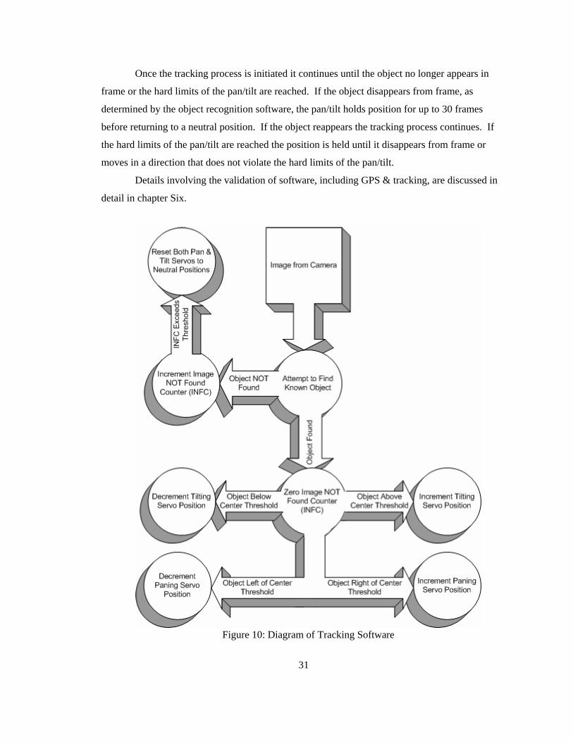
Once the tracking process is initiated it continues until the object no longer appears in
frame or the hard limits of the pan/tilt are reached. If the object disappears from frame, as
determined by the object recognition software, the pan/tilt holds position for up to 30 frames
before returning to a neutral position. If the object reappears the tracking process continues. If
the hard limits of the pan/tilt are reached the position is held until it disappears from frame or
moves in a direction that does not violate the hard limits of the pan/tilt.
Details involving the validation of software, including GPS & tracking, are discussed in
detail in chapter Six.
Figure 10: Diagram of Tracking Software
31

Chapter 6
Experiments
In order to validate the onboard processing system and quantify results several
experiments were performed. These included experiments for onboard system power
consumption, ground versus onboard processing, vision tracking, platform payload limitations,
overall system performance, teleoperation, and waypoint navigation.
6.1 Onboard Processing Experiments
6.1.1 Electrical Power Testing
The first experiment performed was to verify that the onboard system could sustain, via
the onboard LiPo batteries, as long as the maximum endurance of the utilized UVs. Due to the
nature of LiPo cells an 11.1V battery is considered completely spent when it reaches a voltage of
9 V (this is 3V per LiPo cell). Lowering the voltage below 3V per cell will destroy the battery
[14].
To verify the run time of the onboard system it was assembled in full and attached to a
fully charged battery. The entire onboard system was then powered and allowed to run in an idle
state. Idle in this situation refers to the operation of system level processes only. This resulted in
Central Processing Unit (CPU) utilization between 0 and 5 percent. During the experiment GPS
coordinates were transmitted by the receiver but ignored and the servos were command to a
neutral state and held in position. The onboard system operated for approximately 2.0 hours
before the battery voltage reached 9V.
Second, the onboard system was again attached to a fully charged battery and booted.
The operating system immediately ran a user level process that grabbed and filtered images from
the onboard camera. This process kept CPU utilization between 98 and 100 percent. The
onboard system also served a wireless connection providing GPS coordinates to an external
32

device. The onboard system was operated continuously for 40 minuets before battery voltage was
measured to be 9V.
6.1.2 Ground Versus Onboard Processing
The second experiment performed was to quantify the processed frame rate that could be
achieved and to compare this result to a previous experiments using off-board processing [18].
The software utilized for processing the frames was tasked with identifying a simulated mine,
black orb, in varying lighting and background. This was an exact copy of the software utilized in
an off-board processing experiment.
Experiments showed frame rate acquisition and processing at a rate of 80 to 120 frames per
second (fps) using image resolutions of 160x120 pixels. This exceeded camera limitations which
could only grab frames at a rate of 30 fps. Experiments with an off-board processing system,
utilizing a 900MHz video transmitter, showed a maximum realized frame rate of 15 fps using
image resolutions of 320x240 pixels. This limitation was mainly due to the Firewire driver for
the video capture device which utilized DV format image, 720x480 pixels and color depth of 24
bit, at 30 fps which was downsampled to a usable lower resolution image [18]. It is also
noteworthy to mention that ground processing resulted in a high number of false positive
identifications caused by transmission noise and data loss. This type of false positive
identification was removed with the use of the on-board system.
6.1.3 Vision Experiments
Pan/Tilt tracking was also tested to validate functionality. First, experiments were
performed to determine the resolution of the servo control. This was accomplished by mounting
a protractor to the servo and measuring commanded movements. Experiments throughout the
entire range of movement showed a resolution of approximately 0.765º. Next, lab experiments
were performed to validate correct motion. This was performed by initializing the object
recognition software, mentioned in the previous experiment, to identify black objects. A student
with one black shoe then proceeded to walk around the room at a normal pace while the onboard
system tracked the shoe. Last, the onboard system was taken outside and hovered at
approximately 80 feet above the ground and 125 feet from a heavily trafficked road. The onboard
system successfully identified and tracked black vehicles as they passed at approximately 50
33

mph. Note that the software was coded to ignore multiple objects for this experiment and only
identified and tracked single objects within the frame.
6.2 VTOL Experiments
6.2.1 VTOL Payload Limitations
The next experiment performed was to gain insight into the realistic payload capabilities
of the VTOL platform. First, the VTOL was fitted with a small aluminum plate across the skids
to which blocks of weighted aluminum would be added. The platform was then powered and
flown at a starting payload of 2.5 lbs. Every consecutive flight increased the payload to the
platform by 8 ounces. This continued until either the pilot deemed the vehicle unsafe to fly or the
vehicle simply failed to lift the weight. At a payload of 10.5 lbs the VTOL was taken to a hover
at approximately 10 ft where the vehicle was unable to sustain altitude for longer than 2 min. To
ensure personal safety and longevity of the equipment the maximum payload set for this vehicle
was set at 8.5 lbs. This was deemed the optimal payload by the pilot based on vehicle
responsiveness.
6.2.2 Naval Surface Warfare Demonstration
Next, experiments were performed at the Naval Surface Warfare Center in Panama City.
The VTOL UAV was tasked with identifying a target object (black orb) and presenting an
estimated GPS coordinate for that object to an unmanned ground vehicles (UGV) in the area,
Figure 11.
The helicopter was first teleoperated through a series of six GPS coordinates at an
altitude of approximately five meters. This altitude was chosen based on the field of view of the
camera and to prevent false positive identifications experienced at lower altitudes from grass
color and shadows. Each GPS coordinate was approximately fifteen meters from the previous
GPS coordinate and arranged in a raster scan configuration. This resulted in a search area of
approximately 450 square meters. The desired object was then randomly placed within the search
area. Upon visual detection of the designated object the VTOL was teleoperated to a hover and
remained in position until a ground robot arrived. The hovering position of the VTOL was
34
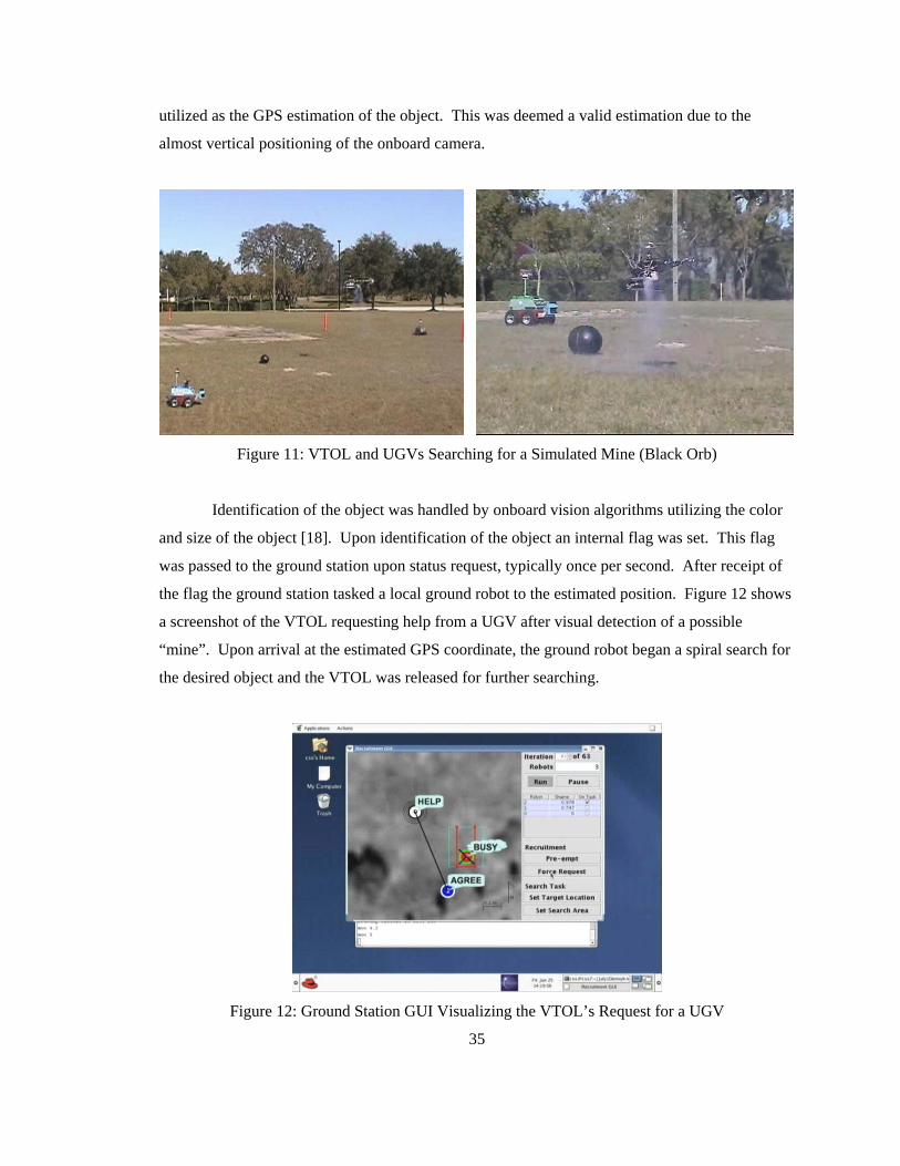
utilized as the GPS estimation of the object. This was deemed a valid estimation due to the
almost vertical positioning of the onboard camera.
Figure 11: VTOL and UGVs Searching for a Simulated Mine (Black Orb)
Identification of the object was handled by onboard vision algorithms utilizing the color
and size of the object [18]. Upon identification of the object an internal flag was set. This flag
was passed to the ground station upon status request, typically once per second. After receipt of
the flag the ground station tasked a local ground robot to the estimated position. Figure 12 shows
a screenshot of the VTOL requesting help from a UGV after visual detection of a possible
“mine”. Upon arrival at the estimated GPS coordinate, the ground robot began a spiral search for
the desired object and the VTOL was released for further searching.
Figure 12: Ground Station GUI Visualizing the VTOL’s Request for a UGV
35

6.2.3 Traffic Surveillance
The last UAV specific experiment performed was to achieve an initial understanding into
the potential and problems with VTOL based traffic surveillance. This was accomplished by
utilizing the onboard processing system and the VTOL UAV, radio controlled, to retrieve aerial
video of traffic.
Video produced by the processing system showed several issues. First, distortion in the
lens created a “rounded” effect on the images, see Figure 13. Roadway that was undoubtedly flat
appeared curved in the image. This also caused distortion to the vehicles traveling on the
roadway and made automated vehicle identification somewhat difficult.
Second, the video was very out of focus. Although it seems that a minor adjustment
would fix the issue it is almost impossible to know the altitude and angle at which the VTOL will
reside while monitoring the traffic. Hence, it is very difficult to focus the lens before flight
suggesting that an auto focus lens or onboard controlled focus would prove useful.
Last, the captured images reveled issues based around iris control. The Fire-I camera
attempts to simulate iris control through software but only bases this control on initial
measurements or when light entry exceeds some large threshold. Since the camera is typically
only inches from the ground when powered on it is heavily shadowed by itself and the VTOL.
As the VTOL gains altitude more light enters into the iris but typically does not exceed the preset
threshold. This results in images that lose distinction in both color and clarity, see Figure 13.
Figure 13: VTOL Images Showing Camera Distortion & Poor Iris Control (left) and Poor Focus
(right)
36

Other issues noted during these experiments were the amount of aerial obstacles present
around roadways, including power lines, tree lines, light post and signs along with the difficulty
involved in finding emergency landings in areas.
6.3 UGV Experiments
6.3.1 Teleoperation
The first experiment performed on the UGV platform was teleoperated control. This was
done to validate the claim that the onboard system was both generic and highly adaptable.
The onboard system was first mounted to the UGV with one minor modification: all
platform servos (speed, gear selection, and steering) were connected directly to the servo
controller. This removed the control from the standard radio controller and gave it to the onboard
processing system. Code was then implemented that gave command of the vehicle to any
machine with login permissions. The user was then able to drive the vehicle, via the keypad,
using a remote machine. The user was also able to utilize the same software that was tested and
implemented for the VTOL including video and status passing as well as GPS and IMU data.
It is noteworthy to mention that time required to pull the onboard system from the VTOL,
mount it to the UGV, and have the onboard system physically fully operational is about 15
minutes.
6.3.2 Autonomous Navigation
The last experiment performed was waypoint navigation of the UGV. This accomplished
to validate the claim that the onboard system possesses the ability to effectively control a
miniature vehicle.
The onboard system was first given a list of desired GPS waypoints. The onboard system
was then command to move the platform to these waypoints stopping at the last one. This was
accomplished by comparing the current GPS coordinate of the UV to the next waypoint. These
two positions were then used to calculate the easterly and northerly error. These two errors were
used to calculate the angle from north from the UV to the waypoint. The heading of the UV was
37
then requested from the IMU and subtracted from the error angle. This angle was used as the
steering angle of the UV’s front wheels.
Make note that due to the limitations of Ackermann steering and the design of the E-
MAXX the vehicles turning angle was limited to 45º. Any calculated angle above 45º or below -
45º was adjusted to this maximum in that direction.
The speed of the UV was controlled by both the distance from the waypoint and the
turning angle of the vehicle. The larger the distance of the UGV from the waypoint the faster the
UGV was command to go. This was limited by a maximum speed of approximately 10 Mph.
This speed was further reduced based on the turning angle of the front tires. This was to avoid
roll over of the vehicle caused by high speed turns. The UGV was also lower limited in speed to
assure that the vehicle did not stop in the event that uneven terrain was reached.
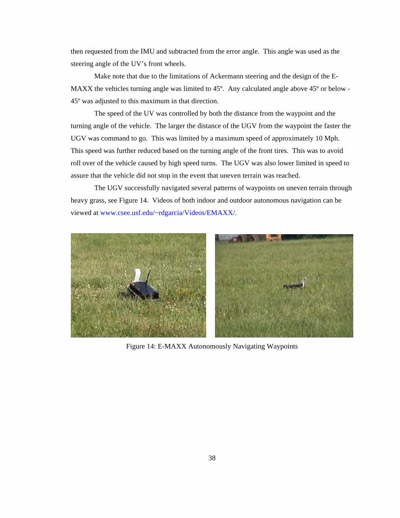
The UGV successfully navigated several patterns of waypoints on uneven terrain through
heavy grass, see Figure 14. Videos of both indoor and outdoor autonomous navigation can be
viewed at www.csee.usf.edu/~rdgarcia/Videos/EMAXX/.
Figure 14: E-MAXX Autonomously Navigating Waypoints
38
Chapter 7
Summary & Future Work
This chapter summarizes the work related to this thesis along with a possible future
related research. Two primary contributions were described by this work. First, the identification
of key characteristics of an onboard system for UVs is identified. This allows for a high level
validation of both hardware and software for typical UV processing systems. It also provides a
design template for a reconfigurable, platform independent, processing system for UVs.
Second, this thesis provides a detailed design of an adaptable onboard processing system
that is both computationally powerful and easily adapted along with its implementation. This is
validated through both lab (indoor) and field (outdoor) experiments. This implantation also
assists in the validation of key characteristics of a UV onboard system.
7.1 Future Work
One drawback to the onboard system described above is the lack of a manual takeover
switch. This limits the safe testing and operation of any autonomous control. Although this is
typically not an issue with UGVs it is a must for all UAVs especially when in the testing phase of
any research. Integration of a safety switch would also help to prevent both injuries and
equipment damage.
Although this thesis’s implemented onboard system follows the constraints described in
chapter 3, there are many possible variations. These can include onboard systems designed
around a very high budget that can utilize custom designed hardware and state of the art
technology. Examples would be 25Hz differential GPS, satellite data transfer, high rate
accelerometers and gyroscopes, and custom platforms. This could also include onboard systems
designed completely around Commercial Off the Shelf (COTS) products.
39

References
[1] H. Aida, Y. Tamura, Y. Tobe, H. Tokuda, “Wireless Packet Scheduling with Signal-to-Noise Ratio Monitoring”, Proceedings of the 25th Annual IEEE Conference on Local Computer Networks, November 2000.
[2] O. Amidi, “An Autonomous Vision-Guided Helicopter,” M.A. thesis, Carnegie Mellon
University, 1996.
[3] W. Burleson, W. Salhany, J. Hudak, “Southern Polytechnic State University Autonomous Remote Reconnaissance System”, http://a-robotics.spsu.edu/ SPSU_paper2005.pdf.
[4] J. Chapuis, C. Eck, H. P. Geering, R. Mudra, B. Schneuwly, R. Sommerhalder: "The Swiss
Entry into the 1996 International Aerial Robotics Competition," Proceedings of the AUVSI, Orlando, FL, July 1996.
[5] Darrin C. Bentivegna, Khaled S. Ali, Ronald C. Arkin, and Tucker Balch. Design and
implementation of a teleautonomous hummer. In Proceedings of Mobile Robots XII, pages 130{138, Pittsburgh, PA, October 1997. International Society for Optical Engineering.
[6] Enhanced Vision System Overview, CMC Electronics,
www.cmcelectronics.ca/En/Prodserv/Commav/commav_evs_overview_en.html (Accessed: 22 January 2005).
[7] D. Ferguson, J. Radke, “Synthetic Vision/Enhanced Vision System Implementation,”
Proceedings, National Telesystem Conference - Commercial Applications and Dual-Use Technology, June 1993.
[8] V. Gavrilets, B. Mettler, E. Feron, “Nonlinear Model for Small-Size Acrobatic Helicopter,”
AIAA Guidance, Navigation, and Control Conference and Exhibit, August 2001.
[9] J. Groven, E. Holk, C. Humbert, J. Krall, D. Schue, “Rose-Hulman Institute of Technology Autonomous Helicopter for the 2004 International Aerial Robotics Competition”.
[10] History, USC Autonomous Flying Vehicle Project, [online] 2004, http://www-
robotics.usc.edu/~avatar /history.htm (Accessed: 17 September 2005).
[11] B.D. Hoffman, E.T.Baumgartner, T.L. Huntsberger, P.S. Schenker, “Improved Rover State Estimation in Challenging Terrain.” Autonomous Robots, Volume 6, Number 2, April 1999, pp. 113-130 (18).
40
[12] N. Holifield, J. Lallinger, G. Underwood “International Aerial Robotics Competition 2004”, University of Texas at Austin IEEE Robot Team Aerial Robotics Project June 1, 2004 http://iarc1.ece.utexas.edu/~lynca/ final_documentation /utiarc2004.pdf.
[13] S. Hrabar, G. S. Sukhatme, “A Comparison of Two Camera Configurations for Optic-Flow
Based Navigation of a UAV Through Urban Canyons” Proceedings, IEEE/RSJ International Conference on Intelligent Robots and Systems, September 2004.
[14] Important Safety Instructions and Warnings, Thunder Power Batteries, [online] 2004,
www.thunderpower-batteries.com/images/THPSafetyWarnings.pdf (Accessed: 22 January 2005).
[15] Johnson, E.N., Calise, A.J., Tannenbaum, A.R., Soatto, S., Hovakimyan, N., and Yezzi, A.J.,
“Active-Vision Control Systems for Complex Adversarial 3-D Environments,” A tutorial, Proceedings of the American Control Conference, 2005.
[16] E. Johnson, P. DeBitetto,C. Trott, and M. Bosse, “The 1996 MIT/Boston University/Draper
Laboratory Autonomous Helicopter System,” Proceedings of the 15th Digital Avionics Systems Conference, 1996.
[17] E. Johnson, S. Mishra, “Flight Simulation for the Development of an Experimental UAV,”
AIAA Modeling and Simulation Technologies Conference and Exhibit, August 2002.
[18] M. Kontitsis, K. P. Valavanis, R. Garcia, “Design, Implementation and Testing of a Vision System for Small Unmanned VTOL Vehicles,” Proceedings, IEEE/RSJ International Conference on Intelligent Robots and Systems, 2005.
[19] Littoral Combat Ship Core Capabilities, Naval Technology .Com, [online] 2005,
http://www.naval-technology.com/projects/littoral/ (Accessed: 17 September 2005).
[20] H. Loose, I. Boersch, J. Heinsohn, K.-U. Mrkor, “RCUBE - A Multipurpose Platform for Mobile Systems in Education,” IEEE International Conference on Mechatronics, June 2004.
[21] L. Mejias, S. Saripalli, G. Sukhatme, P. Cervera, “Detection and Tracking of External Features
in an Urban Environment Using an Autonomous Helicopter,” Proceedings, IEEE International Conference on Robotics and Automation, Spain, April 2005.
[22] M. Musial, U. W. Brandenburg, G. Hommel. “MARVIN - Technische Universität Berlin's
flying robot for the IARC Millennial Event”, Proceedings, Symposium of the Association for Unmanned Vehicle Systems, Orlando, Florida, 2000.
[23] “New-generation autonomous helicopter to create new era of human safety”, CSIRO 2003,
http://www.csiro.au/files/mediaRelease/mr2003/Prhelicopter.htm (Accessed: 2 April 2006).
[24] K. Nordberg, P. Doherty, G. Farneback, P-E. Forssen, G. Granlund, A. Moe and J. Wiklund, “Vision for a UAV helicopter,” IEEE/RSJ International Conference on Intelligent Robots and Systems, Workshop WS6 Aerial Robotics, Lausanne 2002.
41
[25] A. Ollero, J. Ferruz, F. Caballero, S. Hurtado, L. Merino, "Motion compensation and object detection for autonomous helicopter visual navigation in the COMETS system". in IEEE International Conference on Robotics and Automation, New Orleans, LA (USA), April 2004.
[26] A. Proctor, B. Gwin, S. Kannan, A. Koller, H. Christophersen, E. Johnson “Ongoing
Development of an Autonomous Aerial Reconnaissance System at Georgia Tech“, http://controls.ae.gatech.edu/gtar/iarcpapers/git2004.pdf.
[27] RC Power FAQ, EZoneMag, http://www.ezonemag.com/pages/faq/a300.shtml (Accessed: 25
September 2005).
[28] Republic of Singapore Navy Hosts IMDEX Asia 05 Ship Display, Defense World, [online] 2004, http://www.defenseworld.net/World-Military-News.asp/var/6979-DefenseAerospacePressnews-1 (Accessed: 17 September 2005).
[29] RMAX, Yamaha, [online] 2004, http://www.yamaha-
motor.co.jp/global/business/sky/lineup/rmax/index.html (Accessed: 27 January 2005).
[30] “Robotic Naval Ships”, News about Naval Forces, 23 December 2003.
[31] F. Ruffier; N. Franceschini, “Visually guided micro-aerial vehicle: automatic take off, terrain following, landing and wind reaction“, Proceedings, IEEE International Conference on Robotics and Automation, New Orleans, April 2004.
[32] V. Sastry “Vision based detection of autonomous vehicles for pursuit evasion games”, 15th
Triennial World Congress, Barcelona, Spain, 2002.
[33] M. Storvik, “Guidance System for Automatic Approach to a Ship”, M.A. thesis, Norwegian University of Science and Technology, 2003.
[34] Unmanned Ground Vehicle Master Plan, Department of Defense, October 1996.
[35] Unmanned Ground Vehicle Master Plan, Department of Defense, 1999.
[36] Unmanned Ground Vehicle Master Plan, Department of Defense, 2000.
[37] D. Vergun, “Spartan Unmanned Surface Vehicle Envisioned for Array of High-Risk Missions”,
Sea Power, May 2003.
[38] Vision Hardware, USC, [online] 2004, http://www-robotics.usc.edu/~avatar/vision_hw.htm (Accessed: 27 January 2005).
[39] B. R. Woodley, H. L. Jones, E. A. LeMaster, E. W. Frew, and S. M. Rock., “Carrier Phase GPS
and Computer Vision for Control of an Autonomous Helicopter”, ION GPS-96, Kansas City, Missouri, September 1996.
42

[40] B. Woodley, H.Jones, E. Frew, E. LeMaster, Dr. Stephen Rock ”A Contestant in the 1997 International Aerial Robotics Competition”, http://sun-valley.stanford.edu/ papers/WoodleyJFLR:97.pdf.
43

Appendices
44

Appendix 1: Vision System Tables
Table 2: Existing Vision Systems for VTOL Platforms
Institution Machine Vision
Techniques Utilized Processing Type Vehicle (Platform)
Berkeley University [32] No details provided No details
provided BEAR
Georgia Tech [26] [15]
Edge detectors, morphing,
Statistical pattern matching
On- board Rmax by Yamaha
Standford University [39]
[40]
YUV color segmentation,
signum of Laplacian of
Gaussian (sLoG)
On-the-ground Hummingbird Aerospace
Robotic Laboratory at Standford
MIT [4] Template matching On-the-ground Black Star by TSK Rose Hulman IT
(RHIT) [9] Template comparison On-board Bergen Twin
IT Berlin [22] No details provided On-the-ground MARVIN by SSM Technik University of
Texas [12] Edge linking
matching On-the-ground XCell .60
Swiss Federal Institute of
Technology (ETH) [4]
No details provided On-board
integrated in camera
Huner Technik
Carnegie Mellon University [2]
Template matching and RGB color On-the-ground Rmax by Yamaha
USC [32] [39] Omnidirectional, optic flow On-board Bergen Twin
Southern Polytechnic State
Univesity [3]
Stereo vision, Sobel egde detector On-the-ground Vario Robinson R22
Linkoping University, Sweden
(WITAS) [24] No details provided On-board Rmax by Yamaha
45
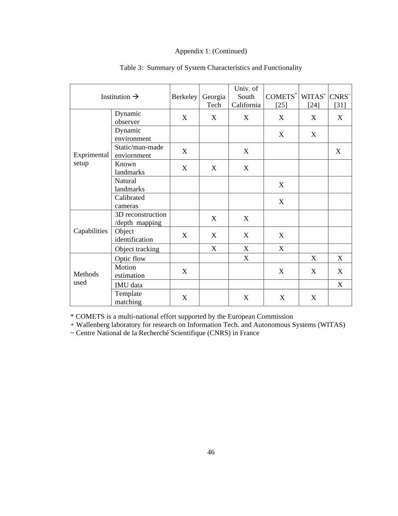
Appendix 1: (Continued)
Table 3: Summary of System Characteristics and Functionality
Institution
Berkeley
Georgia Tech
Univ. of South
California
COMETS*
[25]
WITAS+
[24] CNRS~
[31] Dynamic observer X X X X X X
Dynamic environment X X
Static/man-made enviornment X X X
Known landmarks X X X
Natural landmarks X
Exprimental setup
Calibrated cameras X
3D reconstruction /depth mapping X X
Object identification X X X X
Capabilities
Object tracking X X X Optic flow X X X Motion estimation X X X X
IMU data X
Methods used
Template matching X X X X
* COMETS is a multi-national effort supported by the European Commission + Wallenberg laboratory for research on Information Tech. and Autonomous Systems (WITAS) ~ Centre National de la Recherché Scientifique (CNRS) in France
46