a modular robotic infrastructure to support planetary ... · a modular robotic infrastructure to...
TRANSCRIPT

A Modular Robotic Infrastructure toSupport Planetary Surface Operations
Final ReportOn
Phase 1 StudySponsored by
NASA Institute for Advanced Concepts
Submitted by:
Shane Farritor, PIAssistant Professor
Department of Mechanical EngineeringUniversity of Nebraska-Lincoln
Study Period: July 1999-December 1999Reporting Date: January 9, 2000

2
1 AbstractThis Phase 1 project studied a Planetary Surface Modular Robotic System (PSMRS).
Human exploration of the Moon and Mars is planned for the 2010-2020 timeframe.Extensive use of robots will reduce costs and increase safety. A wide variety of tasks,requiring large a variation in robot capabilities, will be performed. For example, largequantities of regolith may need to be manipulated, requiring bulldozer-like capabilities.Also, delicate scientific instruments may need to be deployed. Creating individual robotsfor each task is not an efficient approach, especially since not all tasks can be foreseen.
The PSMRS could facilitate many NASA missions. The phase I project studied the useof the PSMRS to support human exploration of Mars. This mission fits the 10-20 yeartimeframe corresponding to NIAC objectives.
Revolutionary robotic solutions may be required. The PSMRS is proposed to addressthese unique challenges. Here a robotic infrastructure, rather than an individual robot(s),is proposed. The system is based on a fundamentally modular design to efficientlyaddress the unique challenges of planetary surface operations. The system consists ofmodules that can be assembled into dramatically different robots to perform dramaticallydifferent tasks. This approach promotes efficiency and reliability through adaptability.
The PSMRS does not require revolutionary enabling technologies. Instead, itrepresents a revolutionary approach to robot design compared with robots currently beingdeveloped. The approach could have an important and immediate impact on missionplanning.
The Phase I study successfully demonstrated the concept's feasibility and met theobjectives outlined in the Phase I proposal. Mission requirements were developed,important tasks were identified, and an inventory of modules was created. Robots weresimulated using adequate mathematical models of the environment, robot, and task. Thesimulations demonstrate the scientific feasibility and credibility of the approach.
Nine robots were described as examples of the diversity of robots (and capabilities)that can be produced. All nine robots were constructed using only 26 modules, showingthe benefits of the approach in terms of launch mass and volume. Three of the robotswere simulated performing representative, mission-relevant tasks including soilmanipulation, instrument deployment, and science sample collection. Animation of thesesimulations is included with this report.

3
2 IntroductionA revolutionary approach to space robotics is proposed. It involves designing a robotic
system to be applied to a wide variety of tasks rather than an individual robot(s) for eachtask. This is accomplished through a modular approach to robot design at a veryfundamental level. This concept is used to develop a robotic system to supportexploration called the Planetary Surface Modular Robotic System (PSMRS).
This approach represents a fundamental change in the approach to planetary robots.Robots currently under development for near-term missions (Mars exploration andsample return missions through 2007) are relatively conventional Sojourner-like robots(Volpe et al, 2000; Hayati et al 1998; Schenker, 1997). These are fixed configurationrobots that are designed to perform a few specific tasks (e.g. move and deploy a scienceinstrument). The capabilities of these robots cannot be changed as new missionrequirements arise. These robots are good solutions for the near-term objectives (0-10years), however, a new approach to robot design will be required to meet the future long-term objectives (10-20 years) such as human exploration.
In this new approach modules are assembled to produce a robot for a specific task. Theset of modules, called an inventory, includes actuated joints, links, end-effectors, sensors,and mobility units. The same inventory can be assembled in different configurations fordifferent tasks, see Figure 1.
Figure 1: The Modular Robot Concept
In general, this reconfiguration will need to be done autonomously. Many solutions arepossible. One solution is to have a base module with the capability of manipulating othermodules. A second solution would be to have a pre-assembled modular robot dedicatedto assembling other modular robots. Also, if such a system is used to support humanexploration, an astronaut can perform the assembly.
This approach greatly expands the capabilities of the robotic system over traditionalrobot designs. It also promotes reliability because different configurations cancompensate for the failure of individual modules.
It is possible that some tasks cannot be addressed with the PSMRS and will require aspecific machine (or robot). This will not be known until detailed missions aredeveloped. However, the advantage of the modular system is that a single set of modules
4
can be reconfigured for many tasks and can be adapted to address unforeseen tasks. ThePSMRS may not be able to perform all tasks, but its flexibility has advantages.
In this report the objectives of the Phase 1 study are reviewed (Section 3), the workdone to accomplish these objectives is outlined (Section 4), and the results of this workare presented (Section 5). Finally, the work is summarized (Section 6) and future work isoutlined (Section 7).
3 Phase 1 ObjectivesThe proposed concept represents a fundamentally new approach to planetary robot
design. The preliminary work in this phase 1 study is aimed for the 10-20 yeartimeframe, corresponding with NIAC's objectives and the timeframe NASA proposes forthe human exploration of the Moon and/or Mars.
The PSMRS does not require revolutionary enabling technologies. Instead, itrepresents a revolutionary approach to robot design compared with robots currently beingdeveloped. Since all enabling technologies are currently available, the proposedapproach could have an immediate and important impact on NASA's human explorationplans.
The objective of this project was to study how the modular robot design concept canbest be applied to planetary surface operations, and to significantly influence missionplanners.
The results of this project demonstrate two specific advantages of the modular robotdesign concept:
• the ability of a modular system to accomplish a wide variety of tasks that wouldnormally require numerous traditionally-designed robots
• the increase in system reliability – a factor of the utmost importance on a Marsmission – that is realized with an adaptable modular approach
The project will seek to influence mission planners by demonstrating the usefulness ofmodular robots to improve future mission scenarios. Most mission scenarios include anunmanned “cargo” mission as a precursor to a human landing. Other proposals favor theestablishment of a "robot colony" where many robots will work together to extensivelyexplore a given region. The PSMRS could be useful in both these mission paradigms.
4 Phase 1 WorkThe phase 1 work began with a study of current mission scenarios. Knowledge of
these mission plans will be required to identify representative tasks for robots. From themission scenarios design specifications were developed that describe the requirements forthe system. The specifications were then used to develop a modular inventory fromwhich specific robots, for the representative tasks, could be constructed.
5
4.1 Mission StudiesThe original focus of this study (as presented in the Phase 1 proposal) was to develop a
modular robotic infrastructure to support human Mars exploration. The advantages of themodular concept are not limited to this specific mission so the focus (in Phase II) willshift to include a wider variety of missions including lunar and asteroid exploration aswell as the concept of "robot colonies".
Many proposals have been developed for the further human exploration of the moonand Mars (Zubrin, et. al, 1991; NASA, 1989). The most notable among these reports isreferred to as the Stafford Report or the Space Exploration Initiative (Stafford, 1991).This report, prepared in 1991, outlines America's plans for further exploration of themoon and human exploration of Mars. It is slightly dated, but presents many of the trade-offs and technical challenges to accomplish these exploration goals.
A more recent study, prepared by the Exploration Office and the AdvancedDevelopment Office at the Johnson Space Center , describes a Reference Mission forMars exploration (NASA, 1998). This study presents the Reference Mission with theintent of stimulating "further thought and development of alternative approaches". Thisreference mission is used as the demonstration platform for the modular robotic conceptdescribed in this report. The concept is not limited to this reference mission, but thismission provides a realistic and relevant application for the concept. The mission has thefirst crew landing on Mars in 2010 and future crews occupying this site indefinitely. Thistimeframe fits exactly with the 10-20 year outlook of this Phase 1 study.
This reference mission refers to the use of robotics in the exploration of Mars. Nospecific goals or tasks are directly outlined for robots. However, a robotic precursormission is described. This precursor mission is very similar to the "robot colony"concept except here there is the expectation that humans will arrive. The roboticprecursor mission will have three goals:
• Exploration - gather information about Mars that will be used to determine whatspecific crew activities will be performed and where they will be performed.
• Demonstration - demonstrate the operation of key technologies required for thereference mission
• Operation - land, deploy, operate, and maintain a significant portion of thesurface systems prior to the arrival of the crew.
Each of these goals includes significant challenges for robots and requires a widevariation in capabilities. The first goal of exploration will require a high degree ofmobility. This goal will require robots to travel many (≈ 100) kilometers and performtypical exploration activities such as imaging, scientific measurements, and sampling.This task is similar to the near-term missions (0-10 years) planned by NASA. However,when the exploration activities are complete it would be desirable to use the robothardware for other purposes.
The second and third goals would require robots to deploy, operate, and maintainsurface systems such as in situ resource utilization equipment, science instruments,

6
habitats, and power generation equipment. These are all mechanical systems that willrequire maintenance and repair.
The reference mission also refers to robotic tasks in support of human activities. Onesuch task is to provide mobility for astronauts on the scale of 1 to 10 kilometers. Anotherstated activity includes maintenance of the Mars outpost.
The reference mission is used as a demonstration tool for this project. The diversity inrobot capabilities that will be required is clear. Also, it is not possible to foresee allrequired robot tasks, especially in areas such as maintenance and repair.
4.2 Design SpecificationsThe reference mission contains challenging robot tasks requiring a wide variation in
capabilities. This section outlines the design specifications for the PSMRS.
There are a set of general design specifications that apply to all planetary explorationsystems including tight mass and volume constraints. For obvious reasons, the total massand total volume transported must be minimized. From this point of view the advantageof using a modular system is clear. The total mass/volume dedicated to support systemssuch as robots can be minimized if this mass can be adapted to many tasks (i.e. a set ofmodules that can perform many tasks will require less mass than a specific machinedesigned for each task).
Another general design specification is that the robotic system must be extremelyreliable. The reference mission establishes a permanent Mars outpost with new crewsarriving at the same location indefinitely. This further emphasizes the need forreliability. Part of the reliability requirement means the robots need to be easily repaired.The advantage of a modular approach is that broken modules can be easily replaced inthe same manner that the modules are assembled into robots. Also, a new robot could beconstructed from different modules to perform the task in a new way. The modularsystem also makes it easy to add new functionality (new modules) as different cargo orcrew missions arrive. The incremental build-up of the Martian outpost is a cornerstone ofthe reference mission.
Because of the complexity of the mission, not all tasks can be foreseen. The extremeremoteness of the mission dictates that these unforeseen problems must be solved withthe available elements. This further emphasizes the need to have an adaptable system.
More specific design constraints relevant to the reference mission were also developed.For instance, the reference mission calls for a long-range pressurized rover and a short-range un-pressurized rover. The pressurized system is not included in the PSMRS. Theun-pressurized rover must travel up to ten kilometers. It must be capable of transportingone astronaut (168 kg) and carry 500 kg of useful payload. It must be capable ofclimbing slopes up to 25 degrees and travel at a nominal speed of 10 km/hour. It isprobable that the rover will use an internal combustion engine as a power source (Jochim,1999).
The reference mission includes some "heavier" manipulation tasks such asmanipulating large amounts of soil. This may be needed for science excavation, in situresource utilization, radiation protection, and/or habitat/instrument deployment. These

7
"heavier" tasks have much different requirements in terms of precision and strengthcompared to "lighter" duties such as scientific instrument deployment and assembly.
4.3 Inventory DesignAn inventory of modules was then developed using this information. The inventory
must be capable of producing robots that address the above specifications and tasks.
The goal of inventory design is to create the smallest inventory of modules that can beassembled into the largest diversity of robots (i.e. enough robots to accomplish allrequired tasks).
In inventory design, the level of modularity is important. A low-level inventory wouldcontain very basic elements such motors, gears, bearings and nuts and bolts. A high-levelinventory would contain complex elements such as limbs or arms. A low-level inventoryoffers more flexibility in the robots that can be constructed, however assembly of therobots is much more complex. Conversely a high-level inventory can produce fewerrobots but the assembly is simplified. The inventory designed in this study has amoderate level of modularity offering a balance between the diversity of robots and easeof assembly. Examples of the diversity of robots that can be produced are presented inSection 5.1.
The inventory created is broken into six categories corresponding to the basic elementsof a robot. These categories are base modules, power supplies, actuated joints, kinematiclinks, end-effectors, and sensors.
4.3.1 Module interfaceTo build functional robots from the modules, each module must be capable of
interfacing with all other module. The interface can be broken into three categories: 1)mechanical interface, 2) electrical interface, and 3) information interface.
Three standard sizes were chosen for the mechanical interface. The first two sizes areintended for general purpose, or "light" duty robots, the third size is for "heavy" dutytasks. The module interfaces are squares connecting surfaces of 10cm, 15cm and 30cm.The modules can be attached in 2 orientations as shown in Figure 2, further increasing thediversity of robot assemblies.

8
a) Vertial orientation b) Horizontal orientation
Figure 2: Module Orientation
The interface will also transmit electrical power between modules. The electricalpower will be transferred using two conductors. Each module requiring electrical powerwill have the necessary (voltage) regulation as an integral part of the module.
Information will need to be transferred between modules; this can be done usingelectrical or optical connections. Information transfer can occur in many ways; onemethod would use serial communication such as RS435. Each module will have aprocessor to handle communication between modules and local control (e.g. positioncontrol of a joint).
4.3.2 Base ModulesBase modules are used to support the robots. Power modules and Sensor/Control
modules will be connected to one area of the base module and a serial robot will beconnected to another. Every base requires a power module and a control module tooperate. The power module will provide energy to the system. The control module willperform command and communication operations. Even though every robot requirespower and control these functions are kept separate they can be easily tailored to thespecific robot assembly and task (high/low power; long/short range communications) andcan be easily repaired/replaced.
There are three base modules in the inventory including mobile bases and fixed(immobile) bases, see Table 1. The fixed base (#101) is designed for areas where a taskis frequently performed. It is a very simple module that provides a platform on whichrobots can be constructed.
The mobile bases will expand the usefulness of the PSMRS by expanding is zone ofoperation. There will be two types of mobile bases, one for unmanned operation, and theother for human transport. The unmanned mobile base (#102) can be used for both short-range exploration (< 1km) and for general manipulation tasks.
The human transport base (#103) has been the topic of discussion between the PI andJSC. JSC has awarded the PI a very small research grant to study the design of such avehicle. The human transport base is un-pressurized rover designed provide mobility forone astronaut. It can travel up to ten kilometers and carry 500 kg of useful payload. It isdesigned to climb slopes up to 25 degrees and travel at a nominal speed of 10 km/hour.

9
Table 1: Base Modules
ID# Size (cm)L x W x H
Type Notes
101 125 x 75 x 15 Fixed Base
102 125 x 75 x 35 Unmannedmobile base.
• Autonomous ortele-operation
• Range < 1km• 75 cm outriggers
103 185 x 95 x 70 HumanTransportbase
• Can beautonomously,human or tele-operated
• Range < 10 km
4.3.3 Power ModulesThese modules supply power to the robot assemblies. Table 2 shows the three power
modules included in the inventory. Two provide electrical power through batteries, thesecond generates electrical power using an internal combustion engine.
The reference mission describes fuel (methane) that will be extracted from in situmaterials (atmosphere). This fuel may be used for the assent vehicle and for internalcombustion engines to power various surface systems including the PSMRS. Thismodule (#001) will make it possible to produce powerful robots for long-rangeexploration. The energy that can be produce by such an engine per unit volume is muchgrater than can be stored using current batter technology.
Table 2: Power Modules
ID# Size (cm)L x W x H
Type Notes
001 45 x 30 x 45 InternalCombustionEngine
• Energy is limited byfuel supply.
• Max. Power: 3 kW
002 45 x 30 x 30 Smallelectricalsupply
• Energy: 8 A-hr at 24V• Max. Power: 100 W
003 45 x 30 x 45 Largeelectricalsupply
• Energy: 50 A-hr at24V
• Max. Power: 650 W
10
The two remaining power modules store electrical energy, a small (#002) and a large(#003) unit are included. The use chemical batteries and provide less power and less totalenergy then module #001, but are useful for "lighter" and short-range tasks.
All power modules will need a method to replenish their energy. There will need to bea facility as part of the Mars outpost where all modules will be stored. This facility willalso recharge/refuel the power modules. This facility is not addressed by the phase Istudy.
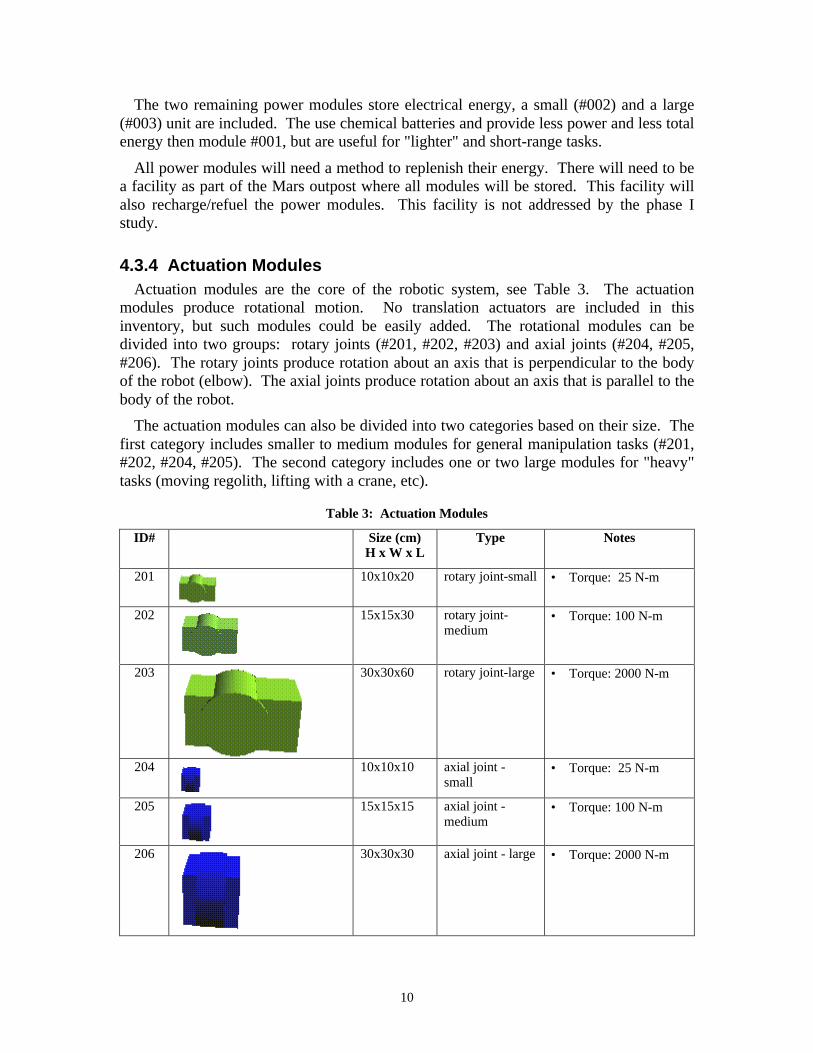
4.3.4 Actuation ModulesActuation modules are the core of the robotic system, see Table 3. The actuation
modules produce rotational motion. No translation actuators are included in thisinventory, but such modules could be easily added. The rotational modules can bedivided into two groups: rotary joints (#201, #202, #203) and axial joints (#204, #205,#206). The rotary joints produce rotation about an axis that is perpendicular to the bodyof the robot (elbow). The axial joints produce rotation about an axis that is parallel to thebody of the robot.
The actuation modules can also be divided into two categories based on their size. Thefirst category includes smaller to medium modules for general manipulation tasks (#201,#202, #204, #205). The second category includes one or two large modules for "heavy"tasks (moving regolith, lifting with a crane, etc).
Table 3: Actuation Modules
ID# Size (cm)H x W x L
Type Notes
201 10x10x20 rotary joint-small • Torque: 25 N-m
202 15x15x30 rotary joint-medium
• Torque: 100 N-m
203 30x30x60 rotary joint-large • Torque: 2000 N-m
204 10x10x10 axial joint -small
• Torque: 25 N-m
205 15x15x15 axial joint -medium
• Torque: 100 N-m
206 30x30x30 axial joint - large • Torque: 2000 N-m
11
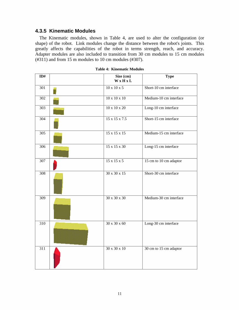
4.3.5 Kinematic ModulesThe Kinematic modules, shown in Table 4, are used to alter the configuration (or
shape) of the robot. Link modules change the distance between the robot's joints. Thisgreatly affects the capabilities of the robot in terms strength, reach, and accuracy.Adapter modules are also included to transition from 30 cm modules to 15 cm modules(#311) and from 15 m modules to 10 cm modules (#307).
Table 4: Kinematic Modules
ID# Size (cm)W x H x L
Type
301 10 x 10 x 5 Short-10 cm interface
302 10 x 10 x 10 Medium-10 cm interface
303 10 x 10 x 20 Long-10 cm interface
304 15 x 15 x 7.5 Short-15 cm interface
305 15 x 15 x 15 Medium-15 cm interface
306 15 x 15 x 30 Long-15 cm interface
307 15 x 15 x 5 15 cm to 10 cm adaptor
308 30 x 30 x 15 Short-30 cm interface
309 30 x 30 x 30 Medium-30 cm interface
310 30 x 30 x 60 Long-30 cm interface
311 30 x 30 x 10 30 cm to 15 cm adaptor

12
4.3.6 End-Effector ModulesThe end-effector modules, shown in see Table 5, allow the robots to perform tasks.
This category includes general manipulation end-effectors such as grippers (#401 ƒ) to be used for tasks such as assembly and sample collecting.
End-effectors with more specialized uses are also included. A large scoop (#403),similar to the bucket on a back hoe, will allow robots to dig and level ground for bothscience and maintenance purposes. A plow blade (#405), similar to a snowplow, isincluded for similar operations. Finally, a wench (#404) is included to create robots withcrane-like capabilities.
Science end-effectors could be added to the inventory to perform specific science tasks.For example, an Alpha Proton X-Ray Spectrometer (APXS), similar to the instrumentused on the sojourner rover, could be added.
Table 5: End-Effector Modules
ID# Size (cm)W x H x L
Type Notes
401 10x10x15 Gripper -small
• General manipulation• 10 cm interface
402 15 x 15 x 22 Gripper -Large
• General manipulation• 30 cm interface
403 30 x 30 x 38 Scoop /Bucket
• digging• science• 10 cm interface
404 15 x 15 x23 Crane/wench • environment manipulation• general surface operations• 10 cm interface
405 90 x 35 x 28 Regolithblade (snowplow)
• environment manipulation• science• radiation shielding• 30 cm interface
4.3.7 Sensor & Control ModulesThe sensor and control modules were not completely developed during this six-month
study. Different sensor packages will be needed depending on whether the robot willoperate autonomously, be tele-operated, or be directly commanded. Sensor modules willbe needed to provide information for navigation and hazard avoidance.
13
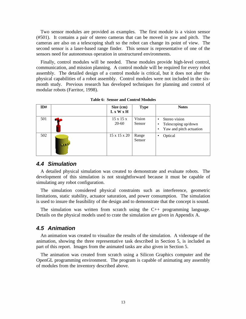
Two sensor modules are provided as examples. The first module is a vision sensor(#501). It contains a pair of stereo cameras that can be moved in yaw and pitch. Thecameras are also on a telescoping shaft so the robot can change its point of view. Thesecond sensor is a laser-based range finder. This sensor is representative of one of thesensors need for autonomous operation in unstructured environments.
Finally, control modules will be needed. These modules provide high-level control,communication, and mission planning. A control module will be required for every robotassembly. The detailed design of a control module is critical, but it does not alter thephysical capabilities of a robot assembly. Control modules were not included in the six-month study. Previous research has developed techniques for planning and control ofmodular robots (Farritor, 1998).
Table 6: Sensor and Control Modules
ID# Size (cm)L x W x H
Type Notes
501 15 x 15 x20-60
VisionSensor
• Stereo vision• Telescoping up/down• Yaw and pitch actuation
502 15 x 15 x 20 RangeSensor
• Optical
4.4 SimulationA detailed physical simulation was created to demonstrate and evaluate robots. The
development of this simulation is not straightforward because it must be capable ofsimulating any robot configuration.
The simulation considered physical constraints such as interference, geometriclimitations, static stability, actuator saturation, and power consumption. The simulationis used to insure the feasibility of the design and to demonstrate that the concept is sound.
The simulation was written from scratch using the C++ programming language.Details on the physical models used to crate the simulation are given in Appendix A.
4.5 AnimationAn animation was created to visualize the results of the simulation. A videotape of the
animation, showing the three representative task described in Section 5, is included aspart of this report. Images from the animated tasks are also given in Section 5.
The animation was created from scratch using a Silicon Graphics computer and theOpenGL programming environment. The program is capable of animating any assemblyof modules from the inventory described above.

14
5 Phase 1 ResultsThis section demonstrates the diversity of robots that can be developed from the
inventory and shows how they can be applied to various mission-relevant tasks.
This inventory is capable of producing many (>108) robots (Farritor, 1998). Ninerobots are described as examples of the diversity of robots and capabilities. Six robotsare briefly described in this Section 5.1 and three different robots are presentedperforming three representative tasks in Sections 5.2, 5.3, and 5.4.
All nine robots shown in this report are produced from only 26 modules of 18 distincttypes. The tasks presented in this report are meant to represent a variety of tasks thatcould be performed by a modular robotic infrastructure. The specific tasks were chosento align with the needs of reference mission describe in Section 4.1. The tasks are notmeant to represent how things will actually be done on a planetary mission. Instead, thetasks demonstrate the advantages of the modular infrastructure approach.
5.1 Robot DiversityTwo short-range mobile manipulation robots are shown in Figure 3 (the end-effectors
are not drawn to the correct scale). Both robots use the #102 base module. This modulehas 4 wheels for mobility and outriggers for stability during manipulation (see animationon video tape). Robot A, Figure 3 a), has a very strong first joint (#203) and a longreach. The robot is capable of lifting 408 kg and has a reach of 2.02 meters (assumesMartian gravity, see Appendix A for further assumptions). This robot uses the internalcombustion engine as a power source. Robot B is a smaller robot with a smaller firstjoint (#102). It can only lift 30 kg and has a reach of only 1.34 meters. However, theconfiguration of its distal joints allow it to manipulate objects in the horizontal plane withlow power consumption.
Both these robots could be used for general manipulation tasks (deploy instruments,collect samples, perform habitat maintenance). However, Robot A would be better suitedto short duration, heavy tasks (replacing an ORU), while Robot B could be used for longrange, light duty tasks (collecting rock samples).
a) Robot ABase: 102Power: 001
Arm: 203,311,202,205,307,201,204,302,401
b) Robot BBase: 102Power: 003
Arm: 203,311,202,205,307,201,204,302,401
Figure 3: Short-Range Manipulation Robots
15
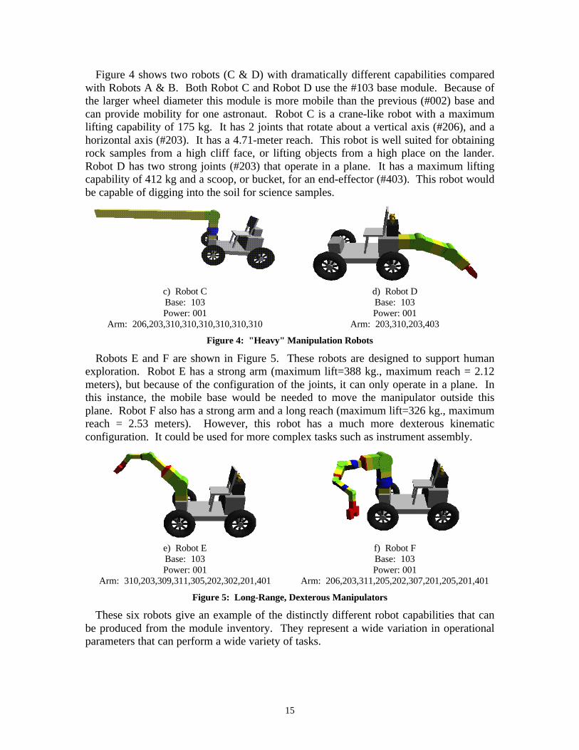
Figure 4 shows two robots (C & D) with dramatically different capabilities comparedwith Robots A & B. Both Robot C and Robot D use the #103 base module. Because ofthe larger wheel diameter this module is more mobile than the previous (#002) base andcan provide mobility for one astronaut. Robot C is a crane-like robot with a maximumlifting capability of 175 kg. It has 2 joints that rotate about a vertical axis (#206), and ahorizontal axis (#203). It has a 4.71-meter reach. This robot is well suited for obtainingrock samples from a high cliff face, or lifting objects from a high place on the lander.Robot D has two strong joints (#203) that operate in a plane. It has a maximum liftingcapability of 412 kg and a scoop, or bucket, for an end-effector (#403). This robot wouldbe capable of digging into the soil for science samples.
c) Robot CBase: 103Power: 001
Arm: 206,203,310,310,310,310,310,310
d) Robot DBase: 103Power: 001
Arm: 203,310,203,403
Figure 4: "Heavy" Manipulation Robots
Robots E and F are shown in Figure 5. These robots are designed to support humanexploration. Robot E has a strong arm (maximum lift=388 kg., maximum reach = 2.12meters), but because of the configuration of the joints, it can only operate in a plane. Inthis instance, the mobile base would be needed to move the manipulator outside thisplane. Robot F also has a strong arm and a long reach (maximum lift=326 kg., maximumreach = 2.53 meters). However, this robot has a much more dexterous kinematicconfiguration. It could be used for more complex tasks such as instrument assembly.
e) Robot EBase: 103Power: 001
Arm: 310,203,309,311,305,202,302,201,401
f) Robot FBase: 103Power: 001
Arm: 206,203,311,205,202,307,201,205,201,401
Figure 5: Long-Range, Dexterous Manipulators
These six robots give an example of the distinctly different robot capabilities that canbe produced from the module inventory. They represent a wide variation in operationalparameters that can perform a wide variety of tasks.

16
5.2 Task 1: Soil ManipulationThe first task is the manipulation of large amounts of Martian/Lunar soil. This may be
required for in situ resource utilization, burying a radioactive power generation unit, solarradiation protection, or preparing ground for construction/deployment of instruments. Arobot was constructed form the modular inventory that is similar to a front loader, Figure6. A manipulator is created with two strong joints (#203) and blade/scoop end effector(#405). The manipulator is attached to a one-person mobility unit (base module). Thisrobot could be programmed to operate autonomously, tele-operated, or directly driven.
To manipulate soil the robot will need large traction forces. This requires good soil tireinteraction and a massive vehicle. Vehicles with large mass are contrary to overallmission constraints. For this reason, this robot my require a drawbar and wench (module#404) to generate the required forward motion on soft soil. This complex interaction wasnot modeled for this phase I study.
Figure 6: Robot "Front Loader"
The animation shows the robot lower the front loader, move forward, and make contactwith the rock (green box). Then the robot pushes the rock out of view.
5.3 Task 2: Instrument DeploymentThe second robot is simulated deploying a science instrument from a lander, Figure 7.
This robot has a long and dexterous 4 joint manipulator attached to the #102 mobile base.The long reach may be required to remove the instrument from the high lander (thedecent engine may require the lander to be tall) or to place the instrument in a difficultlocation (side of a cliff). The mobile base uses 4 outriggers for stability and can move upto 1 km to deploy the instrument.

17
Figure 7: Crane-like "Deployment" Robot
The animation shows the robot approach the lander, deploy the outriggers, and graspthe instrument (green box). The manipulator then moves the instrument to place its massto a stable location (inside the wheel base) and raises the outriggers. Then the robotmoves to a new location and deploys the instrument in the reverse order.
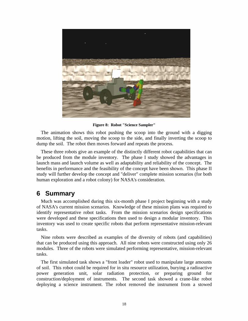
5.4 Task 2: Scientific Sampling / DiggingThe third robot is similar to a small backhoe, Figure 8. This robot would be used to
obtain science samples and to dig into the surface to find these samples. The robot has a4 joint manipulator with a scoop, or bucket (#403), as an end effector. The manipulatoris attached to the rear of the same one-person mobility base module shown in the "frontloader" robot (Figure 6). This base is capable of traveling up to 10 km from the outpostand would greatly improve the scientific exploration capabilities. Again, this robot canbe operated autonomously, tele-operated, or directly driven.
18
Figure 8: Robot "Science Sampler"
The animation shows this robot pushing the scoop into the ground with a diggingmotion, lifting the soil, moving the scoop to the side, and finally inverting the scoop todump the soil. The robot then moves forward and repeats the process.
These three robots give an example of the distinctly different robot capabilities that canbe produced from the module inventory. The phase I study showed the advantages inlaunch mass and launch volume as well as adaptability and reliability of the concept. Thebenefits in performance and the feasibility of the concept have been shown. This phase IIstudy will further develop the concept and "deliver" complete mission scenarios (for bothhuman exploration and a robot colony) for NASA's consideration.
6 SummaryMuch was accomplished during this six-month phase I project beginning with a study
of NASA's current mission scenarios. Knowledge of these mission plans was required toidentify representative robot tasks. From the mission scenarios design specificationswere developed and these specifications then used to design a modular inventory. Thisinventory was used to create specific robots that perform representative mission-relevanttasks.
Nine robots were described as examples of the diversity of robots (and capabilities)that can be produced using this approach. All nine robots were constructed using only 26modules. Three of the robots were simulated performing representative, mission-relevanttasks.
The first simulated task shows a "front loader" robot used to manipulate large amountsof soil. This robot could be required for in situ resource utilization, burying a radioactivepower generation unit, solar radiation protection, or preparing ground forconstruction/deployment of instruments. The second task showed a crane-like robotdeploying a science instrument. The robot removed the instrument from a stowed
19
position high on the lander and transported it to its deployed location. The third tasksimulated a robot digging for science sample. This robot could be used to support long-range (10 km) human exploration.
All results presented in this report were obtained during the six-month study. Thesimulation and animation were written from scratch. No previous results, from otherstudies, were included.
7 Conclusions and Future WorkThe objectives outlined in the phase I proposal were accomplished. The Phase I study
has demonstrated the scientific feasibility of the modular concept using detailed physicalsimulation. It was shown that a modular system could accomplish a wide variety of tasksthat would normally require numerous traditionally designed robots. The phase I studyshowed advantages in launch mass and launch volume as well as adaptability andreliability of the concept.
Future work will include publication of Phase 1 work and results in technical journals.The work will continue to be developed into a graduate student thesis.
The phase II study will further develop the concept and "deliver" complete missionscenarios (for both human exploration and a robot colony) for NASA's consideration.Detailed plans for future work are given in the phase II proposal.

20
8 ReferencesAmbrose, R., Tesar, D., “Modular Robot Connection Design”, ASME 4th International
Conference on Design Theory and Methodology, Scottsdale, AZ, 1992.
Benhabib, B. Zak, G. and Lipton, M., “A Generalized Kinematic Modeling Method forModular Robots,” Journal of Robotic Systems, 1989. vol. 6, no. 5, pp. 545-71.
Bickler, D., "The New Family of JPL Planetary Surface Vehicles," Proceedings ofMissions, Technologies, and Design of Planetary Mobile Vehicles, Toulouse, France,1992.
Chocron, O., Bidaud, P., “Genetic Design of 3D Modular Manipulators”, Proceedings ofthe IEEE International Conference on Robotics and Automation, pp. 223-28, 1997.
Farritor, S., On Modular Design and Planning for Field Robotic Systems, Ph.D. Thesis,Department of Mechanical Engineering, MIT, Cambridge, MA, May, 1998.
Farritor, S., Dubowsky, S., Rutman, N., "On the Rapid Design of Field RoboticSystems", ASME Conference on Design Theory and Methodology, August 1996.
Hayati, S. Volpe, R., et al., "The Rocky 7 Rover: A Mars Sciencecraft Prototype."Proceedings of the IEEE International Conference on Robotics and Automation, 1997.
Jochim, J. David , ER4/Robotic Systems Technology Branch, NASA Johnson SpaceCenter, personal correspondence, August 1998.
NASA, "Report of the 90-Day Study on Human Exploration of the Moon and Mars,"NASA Headquarters, Washington DC, November, 1989.
NASA, Human Exploration of Mars: The Reference Mission (Version 3.0 with June,1998 Addendum) of the NASA Mars Exploration Study Team, Exploration Office,Advanced Development Office, Lyndon B. Johnson Space Center, Houston, TX77058, June, 1998
Paredis, C. J. J., Brown, H. B., Khosla P. K., "A Rapidly Deployable ManipulatorSystem" IEEE International Conference on Robotics and Automation, April 22-28, pp.1434-39, 1996.
Schenker, P., "Lightweight Rovers for Mars Science Exploration and Sample Return,"Intelligent Robots and Computer Vision XVI, SPIE Proc. 3208, Pittsburgh, PA,October, 1997.
Stafford, T., et. al, America at the Threshold: America's Space Exploration Initiative,Report of the Synthesis Group on America's Space Exploration Initiative, 1991.
Tesar, D., and Butler, M. "A Generalized Modular Architecture for Robot Structures,"Manufacturing Review, 1989. vol. 2, no 2.
R. Volpe, E. Baumgartner, P. Schenker, S. Hayati, "Technology Development andTesting for Enhanced Mars Rover Sample Return Operations." Proceedings of the2000 IEEE Aerospace Conference, Big Sky, Montana, March 18-25, 2000.
Zubrin, R., Baker, D., Gwynne, O., "Mars Direct: A Simple, Robust, and Cost EffectiveArchitecture for the Space Exploration Initiative," 29th Aerospace Sciences Meeting,AIAA 91-0326, Reno, NV, 1991.
21
Appendix A: Simulation
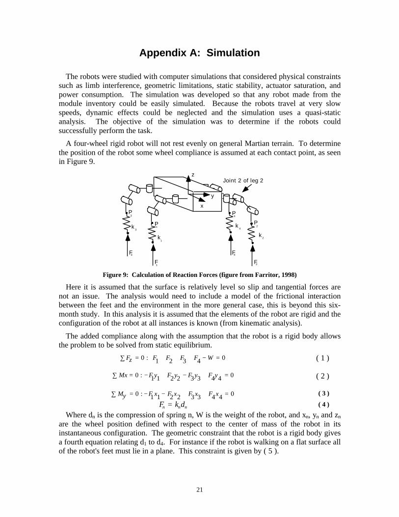
The robots were studied with computer simulations that considered physical constraintssuch as limb interference, geometric limitations, static stability, actuator saturation, andpower consumption. The simulation was developed so that any robot made from themodule inventory could be easily simulated. Because the robots travel at very slowspeeds, dynamic effects could be neglected and the simulation uses a quasi-staticanalysis. The objective of the simulation was to determine if the robots couldsuccessfully perform the task.
A four-wheel rigid robot will not rest evenly on general Martian terrain. To determinethe position of the robot some wheel compliance is assumed at each contact point, as seenin Figure 9.
F1
k 2
3 4
2F3F 4F
1
k k
k
P1
P2
P3 P
4
y
z
x
Joint 2 of leg 2
Figure 9: Calculation of Reaction Forces (figure from Farritor, 1998)
Here it is assumed that the surface is relatively level so slip and tangential forces arenot an issue. The analysis would need to include a model of the frictional interactionbetween the feet and the environment in the more general case, this is beyond this six-month study. In this analysis it is assumed that the elements of the robot are rigid and theconfiguration of the robot at all instances is known (from kinematic analysis).
The added compliance along with the assumption that the robot is a rigid body allowsthe problem to be solved from static equilibrium.
Fz∑ = 0 : F1 + F2 + F3 + F4 − W = 0 ( 1 )
Mx∑ = 0 : − F1y1 + F2y2 − F3y3 + F4y4 = 0 ( 2 )
My∑ = 0 : − F1x1 − F2x2 + F3x3 + F4x4 = 0 ( 3 )
Fn = kndn ( 4 )
Where dn is the compression of spring n, W is the weight of the robot, and xn, yn and zn
are the wheel position defined with respect to the center of mass of the robot in itsinstantaneous configuration. The geometric constraint that the robot is a rigid body givesa fourth equation relating d1 to d4. For instance if the robot is walking on a flat surface allof the robot's feet must lie in a plane. This constraint is given by ( 5 ).

22
A(x4 − x1) + B(y4 − y1) + C(z4 − z1) = 0 ( 5 )
Where A, B, and C are the parameters of a plane defined by the foot positions P1, P2,and P3. This leaves four equations and four unknowns. This can be used to determinethe location of the vehicle on the rough surface of the Martian terrain. The wheelreaction forces can be used with a soil model to determine tire slip.
Power consumption is one of the performance factors considered by the simulation.Power consumption is estimated assuming the actuators are the dominant powerconsuming elements in the system (Dubowsky et al. 1994). With these assumptions, thepower consumed is proportional to the square of the current drawn. For dc motors, thiscurrent is proportional to the applied torque. For the systems considered, it can be shownthat the joint torques required to statically support the system dominate any dynamiceffects (Dubowsky et al., 1994). Therefore, to estimate the power consumption, the jointtorques need to be computed. To do this, the endpoint reaction forces are found.
With knowledge of the manipulator endpoint forces, the joint torques can then becalculated. Figure 10 shows a typical manipulator in the static analysis.
z
x
y
1
3
2
F
P
Figure 10: Calculation of Joint Torques of a Typical Manipulator
The torques at the joints are related to the reaction force, F, by:
T1T 2T 3
= J( θ1 , θ2 , θ 3 )[ ]TF xF yF z
( 6 )
Where [T1,T2,T3] is a vector of the joint torques, J is the Jacobian of the limb, and[Fx,Fy,Fz] is a vector of the reaction forces at the foot (Asada and Slotine, 1986).