a n interoperable gmpls/obs control plane: rsvp and ospf
TRANSCRIPT
An interoperable GMPLS/OBS Control Plane: RSVP and OSPF extensions proposal
P. Pedroso*, D. Careglio*, R. Casellas**, M. Klinkowski*,***, and J. Solé-Pareta* * CCABA, Universitat Politècnica de Catalunya (UPC), Barcelona, Catalunya, Spain ** CTTC, Parc Mediterrani de la Tecnologia (PMT), Castelldefels, Catalunya, Spain
*** National Institute of Telecommunications (NIT), Warsaw, Poland (ppedroso, careglio, mklinkow, pareta)@ac.upc.edu, [email protected]
Abstract— The GMPLS/OBS Control Plane is a bold research topic. Optical Burst Switching (OBS) networks need to be capable to be rapidly reconfigured with the aim of achieving an efficient use of bandwidth, low latency and high degree of transparency. The OBS Control Plane is just a packet switched network requiring a high control complexity. The demands are clear but a well-defined control plane is still an open issue. As one of excellent candidate control plane for most of network scenarios, Generalized Multi-Protocol Label Switching (GMPLS) is being taken as a reference to design such OBS Control Plane. In this paper we first describe the proposal for the interoperable GMPLS/OBS Control Plane and then based on such architecture we propose and analyze some GMPLS protocol extensions that must be done to integrate it properly into OBS networks. Keywords: OBS, Control Plane, GMPLS, extensions.
I. INTRODUCTION GMPLS [1] has been regarded as an excellent
candidate control plane for automatically switched networks: enhances some MPLS issues and handle in a generalized way multiple switching domains with a single set of protocols. It is a common control plane that brings automated end-to-end provisioning of connections, efficient managing of network resources as well as of the QoS levels expected in the new and sophisticated applications, and lower cost of operation by several orders of magnitude [2].
On the other hand, OBS [3] is the envisioned mid-term switching solution for next generation optical backbone networks. At the present time, it is the most feasible option as a trade-off between current available technology and performance while Optical Packet Switching (OPS) still hurdles some shortcomings.
In this paper we propose an architecture model and some protocol extensions to interoperate GMPLS and OBS control layers. Such interoperable GMPLS/OBS control plane would seamlessly enable the coexistence and easy migration between circuit-switched and packet/burst-switched networks.
GMPLS is in principle capable of controlling any technology – to date it is capable to handle multiple switching domains as packet (IP), cell (ATM), time (SDH/SONET), wavelength (WDM) and fiber –, is well studied and standardized, and can be easily extended by IETF when new requirements arise. Indeed, recent efforts are being done to extend it into new domains such as Ethernet switching [4]. Hence, a further step can be envisaged where GMPLS includes optical packet/burst switching domains (OPS/OBS).
As further detailed, the interoperability/integration is achieved by maintaining the GMPLS and OBS control components operating at different timescales; meaning that GMPLS can operate variations in order of minutes/hours/days as in the case of current standards while OBS requires processing time in order of microseconds/milliseconds.
The remainder of this paper is organized as follows. Section 2 presents the proposed GMPLS/OBS architecture. Section 3 identifies the GMPLS protocols shortcomings to operate in OBS networks and describes those needed GMPLS protocol extensions, namely RSVP-TE and OSPF-TE extensions. The conclusions are presented in Section 4.
II. PROPOSAL FOR AN INTEROPERABLE GMPLS/OBS CONTROL PLANE
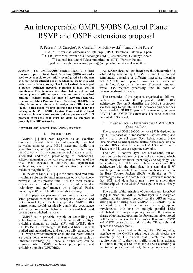
The proposed GMPLS/OBS network [5] is depicted in Fig. 1. It is based on a transparent all-optical data plane and a hybrid control plane. Such hybrid control plane (also referred as interoperable control plane) consists of a specific OBS control layer and a GMPLS control layer. These control layers use separate networks.
The GMPLS control layer uses out-of-band, out-of-fiber (but can be also in-fiber) control architecture, which can be based on whatever technology and topology. On the contrary, the OBS control layer shares the OBS architecture with the data plane; it means that if W wavelengths are available, one wavelength is reserved to the Burst Control Packets (BCPs) while the rest W-1 wavelengths are for the data bursts. It is worth to mention that BCP and data burst must have a strict time relationship while the GMPLS messages can travel freely in its network.
The details of the principle of operation are described in [5]. In brief, the GMPLS control layer is in charge of configuring the virtual topology for the OBS network, setting up and tearing down GMPLS TE Tunnels [6]. In our context, a TE tunnel is seen as a group of wavelengths, with one or multiple parallel LSPs established in a single signaling session. It is also in charge of uploading/updating the forwarding tables stored in the control units of the OBS nodes. It requires RSVP and OSPF protocols to maintain the TE tunnels and update the network status.
A client request is done through the UNI signaling interface to the GMPLS edge node which checks the availability of TE tunnels that match the client requirements: if so, the client traffic is put in an existent TE tunnel (a single LSP or multiple LSPs according to the tunnel properties); if not, the edge node sends a
978-1-4244-1876-3/08/$25.00 ©2008 IEEE
CSNDSP08 - 418 - Proceedings
P C S N - 7 - 4 1 9 - C S N D S P 0 8
RSVP-TE Path message to setup in a two-way process a new TE tunnel (soft reservation - group of wavelengths), according to database updated by OSPF-TE.
O J - a - t x ~ , ~ t {~,.rJbe r / o t a - o l - t ~ P 0
f c ~ f , c::::.::: . . . . . . .
o~ ~ . ....... ~ ............. CaPLS notwork i ~ ; g ; t ; ~ ....
........................................................... ' .'...'~'::.~.'-:~."..".~ ~ N . . . . . . . . ~, r--- •
i ....... ~ ~ i ; ~ ......
~ ~ . .......... ~ ~ . ..........
o~s ~ . o ~ , - . ~.~" " ~ : : m . . . . .
o a t ~ ..... I ~ i ¢ t t a ~ t $
. . . . . . . . . . . . . . . . . . . . . . . . . . . . . . . . . . . . . . . . . . . . . . . .
Figure 1. G M P L S - b a s e d Cont ro l P lane for O B S ne tworks ;
G M P L S cont ro l le r cons is t s in Rou t ing Cont ro l l e r (RC), P ro toco l
Cont ro l l e r (PC) , Opt ica l Connee t ion Cont ro l le r (OCC) , L ink Resou rce M a n a g e r ( L R M ) , Traf f ic P o l i c y (TP) , N e t w o r k Cal l Con t ro l l e r (NCC) .
Consequently, the OBS approximates the connection oriented behavior, i.e., the source-destination path is determined across the network but the burst's wavelength can be chosen at each transit node along the path meaning that the burst is switched from one wavelength to another according to policies or occupancy ratio. However always within the same TE tunnel (different LSPs as is going to be explain further), given the necessary flexibility for TE purposes; if an OBS ingress node wants to transmit a data burst to an OBS egress node, it creates a BCP which must contain a label identifying the (pre-established or existent) TE ttmnel. Such identifier may identify just one LSP or a set of them and, as we explain later on, can be associated to a Call or not. Once the BCP is realized and the offset time is expired, the edge node sends the associated data burst. Both BCP and data burst follow the TE tunnel established by GMPLS. At each intermediate node, the BCP is electrical converted and processed; according to the label and to the forwarding table, the output resources are booked on the fly and the data burst, which is kept optic, is switched correspondingly. This means that no physical reservation is done by GMPLS, it is only in charge of establishing the virtual topology and thus the set of resources available at each node for each TE tunnel.
To be a viable architecture, some GMPLS signaling and routing extensions must be performed. The following section addresses this scope.
III. GMPLS EXTENSIONS
A. General Discussion
To make this interoperable control plane scheme attractive we must guarantee the general purpose of the GMPLS protocols, i.e., the new extensions for OBS should not compromise the overall GMPLS applicability to other switching technology. Such premise should be taken into account every time those extensions are proposed to the GMPLS suite of protocols.
Previous research work [5] defines the baseline of interoperability (mainly at horizontal level) for GMPLS/OBS networks but does not enter in important GMPLS RFC details. Therefore, some extensions to GMPLS signaling and routing protocols are proposed below to provide GMPLS with additional features to work properly over OBS without structural changes in its RFC specifications.
It is important to mention that the following extensions are the exploitation of what the IETF working groups are already contemplating for the GMPLS architecture. Thus, it is observed a convergence between what is offered by GMPLS and our architecture needs. The following two sections point out those GMPLS signaling (RSVP-TE) and routing (OSPF-TE) extensions.
B. Nomenclature
For a clearly interpretation of the proposed extensions, it is worth to first normalize and clarify the nomenclature and concepts described in this section.
Hence, following the nomenclature of RFC and in line with ASON architecture [7][8], we reuse the terms call and connection as follows: we define a GMPLS/OBS Call as an association between endpoints and possibly between key transit points (such as network boundaries) in support of an instance of a OBS service, building a relationship by which subsequent connections may be made. In GMPLS RSVP-TE [6], a Connection is identified with a GMPLS TE tunnel. Commonly, a TE tunnel is identified with a single LSP but it should be noted that for protection, load balancing, and many other functions, a tunnel may be supported by multiple parallel LSPs.
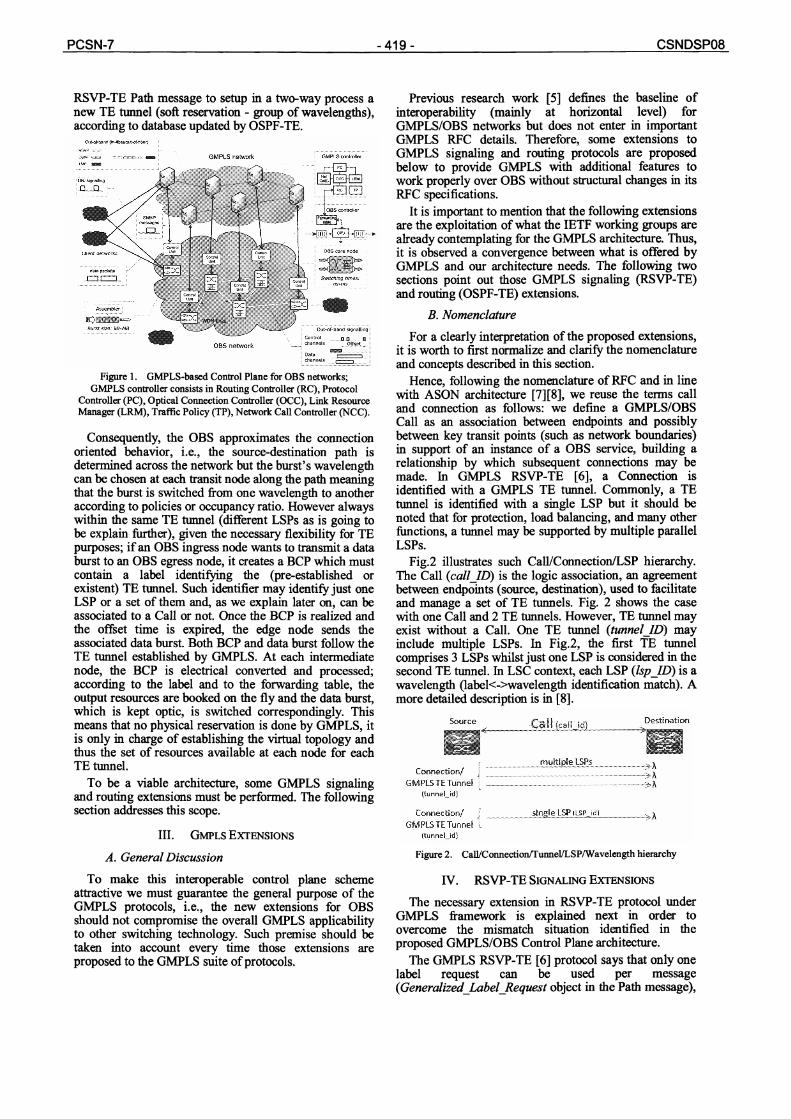
Fig.2 illustrates such Call/Connection/LSP hierarchy. The Call (call_lD) is the logic association, an agreement between endpoints (source, destination), used to facilitate and manage a set of TE ttmnels. Fig. 2 shows the case with one Call and 2 TE tunnels. However, TE tunnel may exist without a Call. One TE ttmnel (tunnel_ID) may include multiple LSPs. In Fig.2, the first TE tunnel comprises 3 LSPs whilst just one LSP is considered in the second TE ttmnel. In LSC context, each LSP (lsp_lD) is a wavelength (label<->wavelength identification match). A more detailed description is in [8].
Destination
Connection/ ~: - ............................................................................................ ~ h "..
GMPLS TE Tunnel .~-h ( t u n n e l _ M }
Connection/ f single LSP (LSP_id) ~ GMPLS TE Tunnel L
( t u n n e l _ i d )
Figure 2. Call/ConnectionCCunneFLSP/Wavelength hierarchy
IV. RSVP-TE SIGNALING EXTENSIONS
The necessary extension in RSVP-TE protocol under GMPLS framework is explained next in order to overcome the mismatch situation identified in the proposed GMPLS/OBS Control Plane architecture.
The GMPLS RSVP-TE [6] protocol says that only one label request can be used per message (Generalized_Label_Request object in the Path message),
i.e., only one single LSP can be requested at a time (and therefore virtual reserves only one wavelength) per signaling message. Conversely, in the considered architecture we have suggested to set up a TE tunnel using one or more LSPs (wavelengths) according to the traffic demands and assuming just one Path-Resv message exchange in both cases. There are three main solutions namely waveband switching, independent LSPs setup and tunnel LSP. This work focuses only in the last one.
In fact, waveband switching is taken into account in [6] (and in related RFCs such as [1][9]) but it is not widely deployed and has the constraint that all the wavelengths of a waveband must be contiguous. The other solution is to use several independent Path-Resv messages in order to set up more than one wavelength for the same TE Tunnel. It does not require any modification but it has scalability drawbacks (the number of messages exchange is high and grow exponentially with errors). For all these reasons the following solution seems the more appropriate.
A. Connection Setup
In general terms, the aim is to setup a connection, TE tunnel, between a pair of edge nodes, inside a Call or not, having a single Path-Resv message exchange with a unique identifier at the forwarding tables, whether the TE tunnel is identified with a single LSP or by multiple LSPs.
The idea is to enhance the goal of the Session object. In consequence, the function of the extended Session object (with call_ID) is to create and represent a tunnel between the source and the destination node which can be useful in the context of our proposed model.
The Session object represents the TE tunnel between an OBS-enabled ingress and egress (table 1). Individual LSPs (wavelengths) can either be established individually or, as we propose, in single signaling sessions to reduce overhead.
The Sender_Template object belonging to the Path message describes a given sender and, in GMPLS, a particular LSP within a single tunnel thanks to the lsp_ID and the sender address (table 1). In such a way, by making use of this, we could extend the number of LSPs announced inside of one Path message repeating the Sender Template object as many times as the number of LSPs inside the TE tunnel. Each LSP would have different lsp_ID under the same tunnel_ID.
This would reduced the number of setup messages exchanged to only one and would make it easier to identify the traffic flow with same QoS requirements (various LSPs with the same characteristics) between the same pair of edge nodes. It also makes easier eventually updates the TE tunnel (increase or reduce its number of wavelengths).
The Label_Set object (also in the Path message) is a plus that helps the source wavelength requests announcement.
Thus, there would be a unique identifier for that set of LSPs (TE Tunnel): tunnel_ID, or, within the Call context, the couple call_ID + tunnel_ID. As in [8] and in order to not generate any backward compatibility issue, the call_ID is not used as part of the processing to determine
the session to which an RSVP signaling message applies but it uniquely identify the source-destination pair.
TABLE I. SESSION AND SENDER_TEMPLATE OBJECT FORMATS
SESSION object
Size Name Description
4 IPv4 tunnel end point address IPv4 address of the egress node for the tunnel
2 Call ID Call identifier -if it exists- if not, must
be zero.
2 Tunnel ID A tunnel identifier that remains constant over the tunnel’s life.
4 Extended Tunnel ID
SENDER_TEMPLATE object
4 IPv4 address IPv4 source address
2 Not used Not used
2 LSP ID LSP identifier
The Session object already defines a 16-bit call_ID
parameter [8], 16-bit tunnel_ID parameter, and a 32-bit Extended_tunnel_ID parameter. For this reason there will be no limitation in the maximum number of tunnels once there are 216+232=260x1012 available identifiers.
Consequently, the Resv message would answer with more than one Label per message, as much as the number of lsp_ID (or Sender_Template objects). However, it still uses one label per wavelength.
Resuming, with just one setup message exchange, i.e., one Path and Resv message exchange between a pair of edge nodes, we can establish a TE tunnel supported by more than one LSP under a unique identifier, tunnel_ID. Moreover, only one Generalized_Label_Request object per Path message is still announced because all those LSPs share the same properties (same QoS, Encoding Switching and Type of Switching). In addition, the Label_Set object is almost mandatory to announce the desired labels (wavelengths). All LSPs are tied together by means of the Call concept and Session object.
At the other end, the egress node would answer with a Resv message containing more than one Generalized_Label object. The egress node must answer within the same proportion of the request (number of LSPs) with as many FlowDescriptors as Senders, limited to a Fixed Filter (FF) reservation style. This would simplify the forwarding tables of each node. The LSP election inside the TE tunnel is locally decided. A standard lambda label format that globally identifies a wavelength is currently under study in [10].
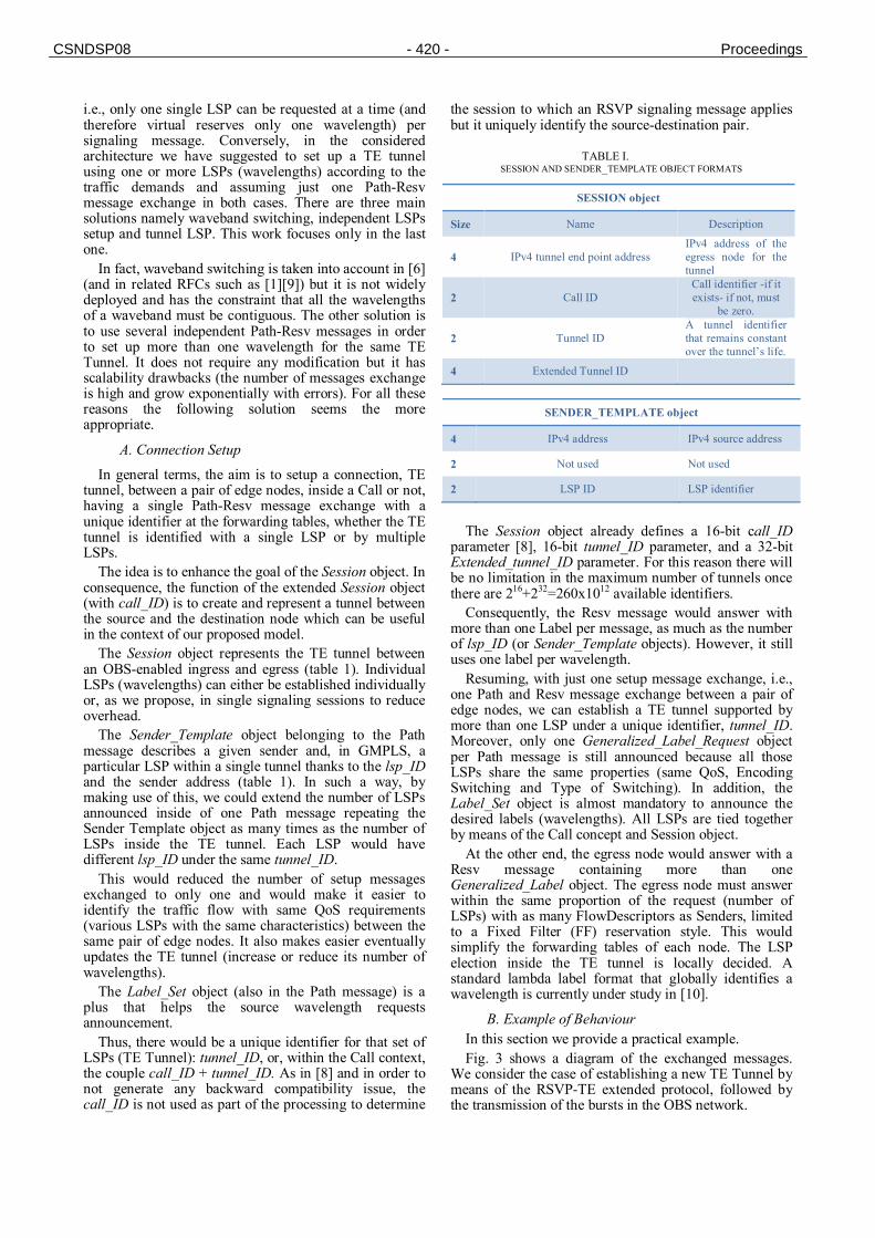
B. Example of Behaviour In this section we provide a practical example. Fig. 3 shows a diagram of the exchanged messages.
We consider the case of establishing a new TE Tunnel by means of the RSVP-TE extended protocol, followed by the transmission of the bursts in the OBS network.
CSNDSP08 - 420 - Proceedings
The first messages are the signaling messages in the GMPLS network namely PATH_message and RESV_message from RSVP-TE protocol to set up the TE tunnel of LSPs. In this case the edge node requires the set up of 8 LSPs; meaning a group of 8 wavelengths. The Optical Connection Controller (OCC) of the GMPLS node is responsible for this. In the example of Fig. 3, we assume that the TE tunnel is established successfully; between each pair of OBS nodes, 8 wavelengths are assigned: (1, 2,5, 8-12) between the first and the second OBS node, (1-8) between the second and the third OBS node, and (3-8, 10,11) for the final link. Remember that we are considering Wavelength Converter Capable OBS nodes. This information is downloaded from the Routing Controller (RC) to the forwarding table of the OBS nodes.
Once the TE tunnel is established, the edge nodes can send the data. Firstly, the BCP is sent by the control wavelength (λ0) carrying the proper label (belonging to the desired tunnel), followed, after the proper offset time, by the data burst. At each core node the BCP is electrical processed while the correspondent data burst is forwarded by means of one of the wavelengths assigned to the TE tunnel. Here, the Control Units of the OBS nodes are in charge of locally selecting the wavelength (among the ones assigned to the TE tunnel) based on the current resource availability. In Fig. 3, the OBS nodes assign to the first burst 1, 4, and 3 for the first, the second and the third link, respectively. The OBS nodes assign different wavelengths to the second burst in the example: 5, 5, and 10, respectively.
It is worth to notice that the following BCPs and data bursts related with the same connection (same tunnel_id) can be sent without another signaling message exchange. This solution also accommodated traffic peak variations by splitting the traffic flow among one, two or the whole set of wavelengths belonging to the tunnel. However, every time it would be possible it is advisable that the output wavelength be the same as the input wavelength to avoid the dispersion issue.
The output label is the correspondent value of the chosen output wavelength (one label->one wavelength). As being study in [10], each numerical label as a correspondent wavelength value (GMPLS LSC).
Figure 3. Diagram of the exchanged messages in an OBS connection.
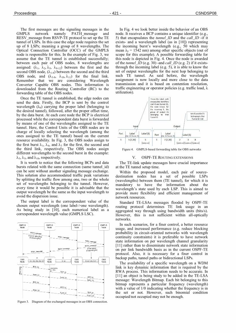
In Fig. 4 we look better inside the behavior of an OBS node. It receives a BCP contains a unique identifier (e.g., 5) that encapsulates the tunnel_ID and the call_ID -if it exists- and a wavelength label (as in [10]) representing the incoming burst’s wavelength (e.g., 50 which may mean λ5 = 1542 nm) among other specific objects (out of scope for this example). A possible forwarding table for this node is depicted in Fig. 4. Once the node is awarded of the tunnel_ID (e.g. 30) -and call_ID (e.g. 2) if it exists- through the incoming label (e.g. 5), it is able to know the set of output wavelengths for the next hop belonging to such TE tunnel. As said before, the wavelength assignment is now locally and more close to the data transmission and it is based on contention resolution, traffic engineering or operator policies (e.g. traffic load, λ utilization).
Figure 4. GMPLS-based forwarding table for OBS networks
V. OSPF-TE ROUTING EXTENSIONS The TE-link update messages have crucial importance
at the TE tunnel setup time. Within the proposed model, each pair of source-
destination nodes has a set of possible LSPs (wavelengths) between them (TE tunnel), for which it is mandatory to have the information about the wavelength’s state used by each LSP. This is aimed to provide more flexibility and efficient management of network resources.
Standard TE-LSAs messages flooded by OSPF-TE routing protocol determines TE link usage in an aggregated way through using bandwidth units (bits/s). However, this is not sufficient within all-optically networks.
In such scenarios, for a finer control, a better resource usage, and increased performance (e.g. reduce blocking probability in circuit-oriented networks with wavelength continuity constraints) it is preferable to have network state information on per wavelength channel granularity [11] rather than to disseminate network state information on per link bandwidth basis as in the current OSPF-TE protocol. Also, it is necessary for a finer control in backup paths, tunnel paths or bidirectional LSPs.
The availability of a specific wavelength on a WDM link is key dynamic information that is required by the RWA process. This information needs to be accurate. In [11] an object is being study to be added in the TE-LSA message: Wavelength Bitmap. Each bit belonging to this bitmap represents a particular frequency (wavelength) with a value of 1/0 indicating whether the frequency is in the set or not. However, such binomial condition occupied/not occupied may not be enough.
Proceedings - 421 - CSNDSP08
CSNDSP08 - 422 - PCSN-7
In [12] the number of states is augmented to cover ampler fields. Using two or three bits instead of one, we increase the number of states from two (21bit) to four (22bits) or eight (23bits) respectively. This gives the flexibility to use them according to our needs.
In the context of OBS, characterized by highly dynamic traffic demands and reservations duration equal to burst time transmission, the former commented network state information (i.e., wavelength granularity) is crucial. There is needed a state that takes into account those wavelengths that are not occupied neither truly occupied but are merely assigned to the TE ttmnels and consequently can be shared by other TE tunnels.
This is important in our model in order to decide which wavelengths can be used by a new TE ttmnel when others are already established.
Our idea is to follow the aforementioned extensions and also inhere this concept to OBS. A new state called Shared is defined for those wavelengths that are not being used neither truly available (i.e. wavelengths that are assigned to the TE tunnel but are not committed and whose utilization depends on the OBS switching). Those wavelengths are shared among different tunnels and are virtually assigned to them. This allows the OBS principle of statistical multiplexing namely different flows can share same resources.
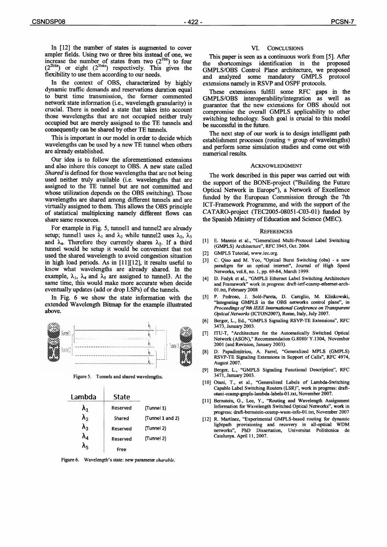
For example in Fig. 5, tunnell and tunnel2 are already setup, tunnell uses Z1 and ~.2 while tunnel2 uses Z2, ~,3 and Z4. Therefore they currently shares Z2. If a third tunnel would be setup it would be convenient that not used the shared wavelength to avoid congestion situation in high load periods. As in [11][12], it results useful to know what wavelengths are already shared. In the example, Z~, Z4 and Z5 are assigned to tunnel3. At the same time, this would make more accurate when decide eventually updates (add or drop LSPs) of the tunnels.
In Fig. 6 we show the state information with the extended Wavelength Bitmap for the example illustrated above.
. . . . . . . . . . . . . . . . . . . . . . . . . . . . . . . . . . . . . . . . 2 . . . . . . . : . . . . .
i__i ~ - /
Figure 5. Tunnels and shared wavelengths.
Tunnd3~
Lambda
~,2 ~3
State
Reserved
Shared
Reserved
Reserved
Free
{Tunnel 1)
(Tunnel 1 and 2)
~unnel 2)
Funnel 2}
Figure 6. Wavelength's state: new parameter sharable.
VI. CONCLUSIONS
This paper is seen as a continuous work from [5]. After the shortcomings identification in the proposed GMPLS/OBS Control Plane architecture, we proposed and analyzed some mandatory GMPLS protocol extensions namely in RSVP and OSPF protocols.
These extensions fulfill some RFC gaps in the GMPLS/OBS interoperability/integration as well as guarantee that the new extensions for OBS should not compromise the overall GMPLS applicability to other switching technology. Such goal is crucial to this model be successful in the future.
The next step of our work is to design intelligent path establishment processes (routing + group of wavelengths) and perform some simulation studies and come out with numerical results.
ACKNOWLEDGMENT
The work described in this paper was carried out with the support of the BONE-project ("Building the Future Optical Network in Europe"), a Network of Excellence funded by the European Commission through the 7th ICT-Framework Programme, and with the support of the CATARO-project (TEC2005-08051-C03-01) funded by the Spanish Ministry of Education and Science (MEC).
REFERENCES
[1] E. Mannie et al., "Generalized Multi-Protocol Label Switching (GMPLS) Architecture", RFC 3945, Oct. 2004.
[2] GMPLS Tutorial, www.iec.org. [3] C. Qiao and M. Yoo, "Optical Burst Switching (obs) - a new
paradigm for an optical internet", Journal of High Speed Networks, vol.8, no. 1, pp. 69-84, March 1999.
[4] D. Fedyk et al., "GMPLS Ethernet Label Switching Architecture and Framework" work in progress: draft-ietf-ccamp-ethernet-arch- 01.txt, February 2008
[5] P. Pedroso, J. Sol6-Pareta, D. Careglio, M. Klinkowski, "Integrating GMPLS in the OBS networks control plane", in Proceedings of gth IEEE International Conference on Transparent Optical Networks (ICTON2007), Rome, Italy, July 2007.
[6] Berger, L., Ed., "GMPLS Signaling RSVP-TE Extensions", RFC 3473, January 2003.
[7] ITU-T, "Architecture for the Automatically Switched Optical Network (ASON)," Recommendation G.8080/Y.1304, November 2001 (and Revision, January 2003).
[8] D. Papadirnitriou, A. Farrel, "Generalized MPLS (GMPLS) RSVP-TE Signaling Extensions in Support of Calls", RFC 4974, August 2007.
[9] Berger, L., "GMPLS Signaling Functional Description", RFC 3471, January 2003.
[10] Otani, T., et al., "Generalized Labels of Lambda-Switching Capable Label Switching Routers (LSR)", work in progress: draft- otani-ccamp-gmpls-lambda-labels-O 1.txt, November 2007.
[11] Bernstein, G., Lee, Y., "Routing and Wavelength Assignment Information for Wavelength Switched Optical Networks", work in progress: draR-bernstein-ccamp-wson-info-01.txt, November 2007
[12] R. Martinez, "Experimental GMPLS-based routing for dynamic lightpath provisioning and recovery in all-optical WDM networks", PhD Dissertation, Universitat Polithenica de Catalunya. April 11, 2007.