a neuromorphic vlsi head direction cell system
TRANSCRIPT
> TCAS-I 8378 <
1
Abstract—The head direction (HD) cell system in the brain of mammals is thought to be part of the neural circuitry supporting their spatial navigation capabilities. In this paper we present a neuromorphic VLSI (very large scale integration) system that models the operation of the HD system. Relying on spiking neurons and attractor dynamics, this system can be used to represent and retain the current estimate of head orientation in the environment and integrate the angular velocity to update this estimate. The presented system is more than a simple integrator and orientation memory; it is a first step towards modeling sophisticated biological navigation systems that use multimodal sensory and motor information to continually realign themselves based on experience.
Index Terms—Attractor dynamics, head direction, navigation, neuromorphic VLSI, spiking neurons.
I. INTRODUCTION The hippocampus, the entorhinal cortex, and the
postsubiculum are areas of the mammalian brain that have been shown to be heavily involved in spatial navigation related tasks [1-4]. In rats, where spatial navigation and memory have been studied using two-dimensional environments, neural recordings from the postsubiculum have shown the presence of neurons called head direction (HD) cells, that are tuned to the orientation of the animal’s head in space; a given neuron fires whenever the animal’s head is facing its preferred orientation and is silent otherwise [3, 5]. It is widely believed that the activity of these cells is updated using self-motion signals (e.g. head rotation velocity as detected by vestibular sensors), spatial memory (e.g. associating landmarks with particular directions), or both [5-8]. Beyond simply providing a readout of the current orientation, these neurons collectively maintain an estimate of the head orientation by sustaining its activity and by shifting this activity from one part of the neural population to another to represent changes in orientation. Accurate integration of velocity signals to compute position or orientation, however, requires carefully matched neural and synaptic properties.
Manuscript received, December 29, 2009. This work was supported in part by a grant from the Air Force Office of Scientific Research (FA95500710446) and the National Science Foundation (CCF0347573).
T. M. Massoud is with the Department of Electrical and Computer Engineering and Institute for Systems Research, University of Maryland, College Park, MD 20742 USA (e-mail: [email protected]).
T. K. Horiuchi is with the Department of Electrical and Computer Engineering, the Institute for Systems Research at the University of Maryland, College Park, MD 20742 USA, and with the Neuroscience and Cognitive Sciences Program University of Maryland, College Park, MD 20742 USA (e-mail: [email protected]).
Although biological neurons and their synaptic interconnections are assumed to be adaptive within any given system to compensate for mismatched characteristics, accurate calibration across all positions and rotation velocities is likely to be an elusive goal. Due to the nonlinearities inherent in all components of the system, without calibration, angular velocity integration is likely to be nonlinear, location-dependent, and prone to drifting towards attractor locations. On the other hand, experiments with rats show that when stable spatial landmarks are present, the response of the HD neurons does not drift, which led to the conclusion that simple associative learning is used to correct for drift in the activity of the network [8, 9].
Since its discovery in 1984, many theories have been postulated to explain how the HD system works and to provide a biologically-plausible neural circuit for its operation. Nearly all of the proposed models have suggested that the network of HD cells can be described to be a recurrent neural network which exhibits a continuum of stable attractor states. Each attractor is represented by the persistent activity of a subset of the neurons (i.e., a bump of activity) acting as a memory for a certain head orientation. In the absence of any head movement, the network remains in its latest state, maintaining the current estimate of head orientation. When the head rotates, angular velocity information is used by the network to move the bump of activity through the network to represent the new head orientation [10-14].
Whereas most models for HD cells capture the general behavior of the system by adopting mean rate representations for the activity of neuron populations, some models use spiking neurons to model the HD system [15-17]. The operation of these models, however, relies on large neural populations with matched parameters to implement the HD system which makes them more suitable for software implementation rather than for analog hardware.
Since our interest is to study spiking neural networks and to build engineering systems that can act like the neural circuits in the brain, we are investigating a novel spiking neural implementation for the HD system that requires only a small number of neurons.
In this paper we consider how a recurrent network of spiking neurons can successfully achieve the same functional behavior of HD cells without using large neural populations. Our model incorporates modifications to conventional HD models by using a disinhibition-based gating mechanism to allow precise control of the movement of the neural activity and thus angular velocity integration. We show test measurements from this VLSI-based, spiking neuron network and provide a mathematical description of the system’s
Tarek M. Massoud, Timothy K. Horiuchi, Member, IEEE
A Neuromorphic VLSI Head Direction Cell System
> TCAS-I 8378 <
2
--
++
-+
-+ -
+
- +
behavior. Implemented as a system of custom mixed-mode (analog
and asynchronous digital) electronic circuits using integrated circuit technology with some commercially-available programmable microprocessors, this hardware implementation is suitable for real-time operation in a robotics context. Portions of this work have been published in conference proceedings [18].
II. HD SYSTEM MODEL In this work, we are interested in developing a biologically-
plausible model for the rat HD system that can be directly mapped onto neuromorphic analog hardware. To model biological HD cells using an artificial system, the system must exhibit some key features of the biological system: 1) the system should be capable of maintaining stable activity in the network (i.e., act as a memory) in the absence of external stimuli, and 2) head motion-related signals should be used to move the activity in the network smoothly from the current location to a new location representing the new orientation of the head in space [14]. The model we present here for maintaining stable bumps of activity is inspired from previously presented HD models in the literature (section I) and this model can be directly implemented in hardware with minimal difficulty. To move the activity bump across the field of HD neurons in response to the head’s angular velocity, however, we propose a novel biologically-plausible model.
A. Stable Activity in the Network To create stable, sustained spiking activity in the absence
of external stimulation, the HD system is modeled as a ring of recurrently interconnected neurons. Each neuron in the ring has a neighborhood of neurons with which it has fixed mutual connections whereas no direct connections exist with neurons outside of this neighborhood. The weights of the connections between the neuron and its neighborhood has a “Mexican-hat” shape, with two groups of projections: excitatory projections to nearest neighbors with decaying weights as the separation
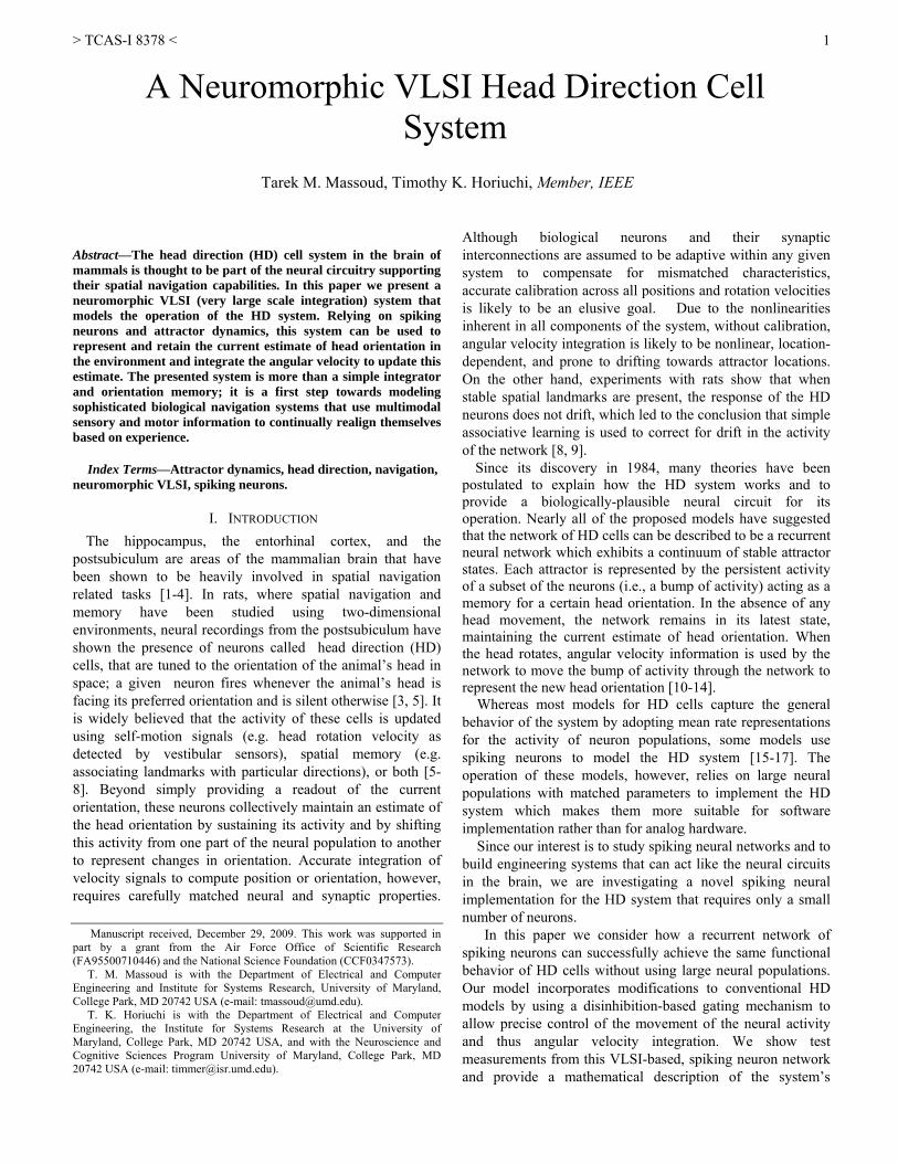
between the neurons increases, and a group of inhibitory projections that are locally strong then decay with increasing interneuron separation. Fig. 1 shows the projection pattern used in our experiments. A ring of neurons with such connectivity and a weak, constant input current driving them all to fire will exhibit activity in the shape of one or more groups of active neurons forming bumps of activity [19-21].
For the HD system operation, a unique representation is
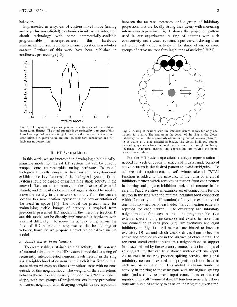
needed for each direction in space and thus a single bump of active neurons is the desired pattern to avoid ambiguity. To achieve this requirement, a soft winner-take-all (WTA) function is added to the network, in the form of a global inhibitory neuron which receives excitation from each neuron in the ring and projects inhibition back to all neurons in the ring. In Fig. 2 we show an example set of connections for one neuron in the ring with the minimal neighborhood connection width (for clarity in the illustration) of only one excitatory and one inhibitory neuron on each side. This connection pattern is repeated for each neuron. The excitatory and inhibitory neighborhoods for each neuron are programmable (via external spike routing processors) and extend to more than one connection in each pool (e.g., six excitatory and eight inhibitory in Fig. 1). All neurons are biased to have an excitatory DC current which weakly drives them to become active and produce spikes in the absence of other inputs. The recurrent lateral excitation creates a neighborhood of support (of a size defined by the excitatory connectivity) for bumps of spiking activity that can be sustained without external input. As neurons in the ring produce spiking activity, the global inhibitory neuron is excited and projects inhibition back to each neuron in the ring. This global inhibition limits the activity in the ring to those neurons with the highest spiking rates (induced by recurrent input connections or external inputs). This soft “winner-take-all” function generally allows only one bump of activity to exist on the ring at a given time.
Fig. 2. A ring of neurons with the interconnections shown for only oneneuron for clarity. The neuron in the center of the ring is the globalinhibitory neuron. The connectivity allows one group of neurons (“bump”)to be active at a time (shaded in black). The global inhibitory neuron(shaded gray) normalizes the total network activity through inhibitoryfeedback. Additional neurons and connectivity for moving the bumpactivity are not shown.
Fig. 1. The synaptic projection pattern as a function of the relativeinterneuron distance. The actual strength is determined by a product of thiskernel and a global current setting. A positive value indicates an excitatoryconnection, a negative value indicates an inhibitory connection and “0”indicates no connection.
> TCAS-I 8378 <
3
Bump Neurons
Dis-Inhibition Neurons
Rotation Neurons
Left Speed SignalRight Speed Signal
Stable Bump at new location
The head is rotating left
Stable Bump
If the lateral connections are balanced, the bump of activity will remain at its current location on the ring.
B. Moving the “Bump” In our network, each group of active neurons (attractor
state) in the ring is associated with a certain head direction in the environment. As the head is turned (due to head movements or combined head-body movements), the system will receive input signals coding for the angular velocity of the head. This head velocity information is provided to the system as left and right speed signals which drive the bump to move around the ring to represent the new head direction. This corresponds functionally to a mathematical integration of the head’s velocity information to compute the head angle. The neurons and connectivity used to perform this function are shown in Fig. 3.
The “bump neurons” in Fig. 3 are the same neurons shown
in Fig. 2 with the bump-layer connections hidden. At each location in the ring a “left-rotation” and a “right-rotation” neuron receive global head rotation signals. For leftward (rightward) rotation, these signals produce spiking activity in just the left-rotation neuron (right rotation neuron) proportional to leftward (rightward) speed.
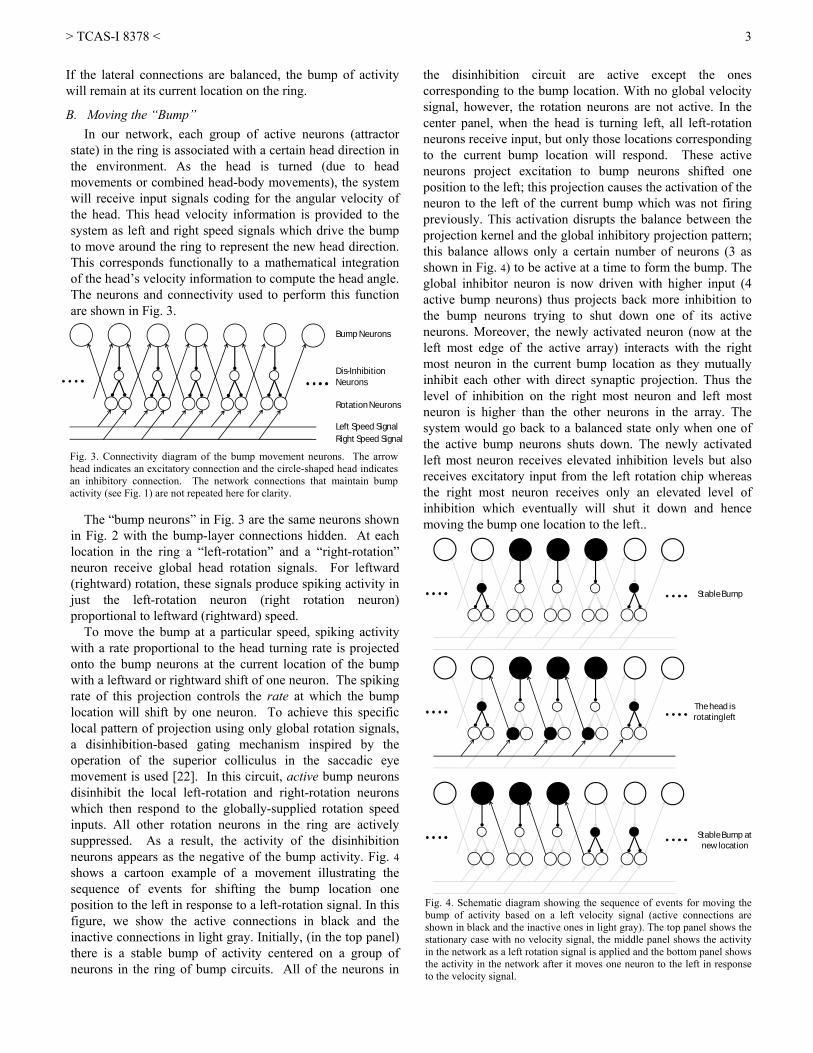
To move the bump at a particular speed, spiking activity with a rate proportional to the head turning rate is projected onto the bump neurons at the current location of the bump with a leftward or rightward shift of one neuron. The spiking rate of this projection controls the rate at which the bump location will shift by one neuron. To achieve this specific local pattern of projection using only global rotation signals, a disinhibition-based gating mechanism inspired by the operation of the superior colliculus in the saccadic eye movement is used [22]. In this circuit, active bump neurons disinhibit the local left-rotation and right-rotation neurons which then respond to the globally-supplied rotation speed inputs. All other rotation neurons in the ring are actively suppressed. As a result, the activity of the disinhibition neurons appears as the negative of the bump activity. Fig. 4 shows a cartoon example of a movement illustrating the sequence of events for shifting the bump location one position to the left in response to a left-rotation signal. In this figure, we show the active connections in black and the inactive connections in light gray. Initially, (in the top panel) there is a stable bump of activity centered on a group of neurons in the ring of bump circuits. All of the neurons in
the disinhibition circuit are active except the ones corresponding to the bump location. With no global velocity signal, however, the rotation neurons are not active. In the center panel, when the head is turning left, all left-rotation neurons receive input, but only those locations corresponding to the current bump location will respond. These active neurons project excitation to bump neurons shifted one position to the left; this projection causes the activation of the neuron to the left of the current bump which was not firing previously. This activation disrupts the balance between the projection kernel and the global inhibitory projection pattern; this balance allows only a certain number of neurons (3 as shown in Fig. 4) to be active at a time to form the bump. The global inhibitor neuron is now driven with higher input (4 active bump neurons) thus projects back more inhibition to the bump neurons trying to shut down one of its active neurons. Moreover, the newly activated neuron (now at the left most edge of the active array) interacts with the right most neuron in the current bump location as they mutually inhibit each other with direct synaptic projection. Thus the level of inhibition on the right most neuron and left most neuron is higher than the other neurons in the array. The system would go back to a balanced state only when one of the active bump neurons shuts down. The newly activated left most neuron receives elevated inhibition levels but also receives excitatory input from the left rotation chip whereas the right most neuron receives only an elevated level of inhibition which eventually will shut it down and hence moving the bump one location to the left..
Fig. 3. Connectivity diagram of the bump movement neurons. The arrowhead indicates an excitatory connection and the circle-shaped head indicatesan inhibitory connection. The network connections that maintain bumpactivity (see Fig. 1) are not repeated here for clarity.
Fig. 4. Schematic diagram showing the sequence of events for moving thebump of activity based on a left velocity signal (active connections areshown in black and the inactive ones in light gray). The top panel shows thestationary case with no velocity signal, the middle panel shows the activityin the network as a left rotation signal is applied and the bottom panel showsthe activity in the network after it moves one neuron to the left in responseto the velocity signal.
> TCAS-I 8378 <
4
Synapses
Neurons
AER
Our model for moving the activity in the HD system is different than previously proposed models [10-15] in that our synaptic projections are fixed and do not need to rapidly change to provide an asymmetrical projection and shift the bump of activity. Furthermore, many previous models move the bump by suppressing its “backside” but in our model, we move the bump by expanding the excitation in the direction of motion.
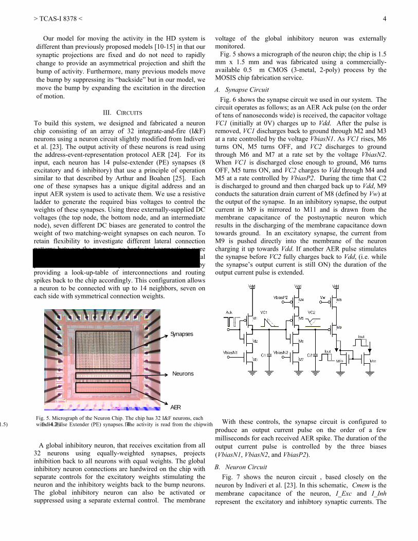
III. CIRCUITS To build this system, we designed and fabricated a neuron chip consisting of an array of 32 integrate-and-fire (I&F) neurons using a neuron circuit slightly modified from Indiveri et al. [23]. The output activity of these neurons is read using the address-event-representation protocol AER [24]. For its input, each neuron has 14 pulse-extender (PE) synapses (8 excitatory and 6 inhibitory) that use a principle of operation similar to that described by Arthur and Boahen [25]. Each one of these synapses has a unique digital address and an input AER system is used to activate them. We use a resistive ladder to generate the required bias voltages to control the weights of these synapses. Using three externally-supplied DC voltages (the top node, the bottom node, and an intermediate node), seven different DC biases are generated to control the weight of two matching-weight synapses on each neuron. To retain flexibility to investigate different lateral connection patterns between the neurons, no hardwired connections were implemented between the neurons on the chip; a digital processor was used to implement the connections by providing a look-up-table of interconnections and routing spikes back to the chip accordingly. This configuration allows a neuron to be connected with up to 14 neighbors, seven on each side with symmetrical connection weights.
A global inhibitory neuron, that receives excitation from all
32 neurons using equally-weighted synapses, projects inhibition back to all neurons with equal weights. The global inhibitory neuron connections are hardwired on the chip with separate controls for the excitatory weights stimulating the neuron and the inhibitory weights back to the bump neurons. The global inhibitory neuron can also be activated or suppressed using a separate external control. The membrane
voltage of the global inhibitory neuron was externally monitored.
Fig. 5 shows a micrograph of the neuron chip; the chip is 1.5 mm x 1.5 mm and was fabricated using a commercially-available 0.5 μm CMOS (3-metal, 2-poly) process by the MOSIS chip fabrication service.
A. Synapse Circuit Fig. 6 shows the synapse circuit we used in our system. The
circuit operates as follows; as an AER Ack pulse (on the order of tens of nanoseconds wide) is received, the capacitor voltage VC1 (initially at 0V) charges up to Vdd. After the pulse is removed, VC1 discharges back to ground through M2 and M3 at a rate controlled by the voltage VbiasN1. As VC1 rises, M6 turns ON, M5 turns OFF, and VC2 discharges to ground through M6 and M7 at a rate set by the voltage VbiasN2. When VC1 is discharged close enough to ground, M6 turns OFF, M5 turns ON, and VC2 charges to Vdd through M4 and M5 at a rate controlled by VbiasP2. During the time that C2 is discharged to ground and then charged back up to Vdd, M9 conducts the saturation drain current of M8 (defined by Vw) at the output of the synapse. In an inhibitory synapse, the output current in M9 is mirrored to M11 and is drawn from the membrane capacitance of the postsynaptic neuron which results in the discharging of the membrane capacitance down towards ground. In an excitatory synapse, the current from M9 is pushed directly into the membrane of the neuron charging it up towards Vdd. If another AER pulse stimulates the synapse before VC2 fully charges back to Vdd, (i.e. while the synapse’s output current is still ON) the duration of the output current pulse is extended.
With these controls, the synapse circuit is configured to
produce an output current pulse on the order of a few milliseconds for each received AER spike. The duration of the output current pulse is controlled by the three biases (VbiasN1, VbiasN2, and VbiasP2).
B. Neuron Circuit Fig. 7 shows the neuron circuit , based closely on the
neuron by Indiveri et al. [23]. In this schematic, Cmem is the membrane capacitance of the neuron, I_Exc and I_Inh represent the excitatory and inhibtory synaptic currents. The
Fig. 5. Micrograph of the Neuron Chip. The chip has 32 I&F neurons, eachwith 14 Pulse Extender (PE) synapses. The activity is read from the chip
> TCAS-I 8378 <
5
DisInh.Chip
Bump ChipPIC PIC
PIC
PIC
Left Speed Right Speed
Right Rotation
Chip
Left Rotation
Chip
neuron’s DC bias current is provided by transistor M1 whose gate is controlled by the voltage Vinj. Vinj is a global parameter for all the neurons in the chip except for the global inhibitory neuron. Transistor M2 provides the leak current that continuously discharges the membrane capacitance, Cmem. This leak current is controlled by Vleak, also a global parameter for all neurons on the chip. M6 and M7 are a source follower that raises and adjusts the neuron’s threshold voltage for firing a spike. The circuit operates as follows; Cmem integrates the input currents of the neuron, resulting in a voltage Vmem. When Vmem rises above the threshold voltage of the neuron controlled by Vsf and the inverter (M10 and M11), V2 is pulled towards ground which activates the positive feedback current path through M3, M4, and M9 and accelerates the rise of Vmem and hence the spiking of the neuron. As V2 drops to ground, the inverter (defined by M17 and M18) switches state to output high which switches M20 (ON) to pull down on the AER request line (Req/). When the AER system acknowledges the request, it sends back an active-low signal (Ack/) to activate the inverter (defined by M14 and M15) through M12 and M13. Pulling V3 to a high state resets Vmem to ground using M5. As Vmem drops to zero, V1, V2, and V3 switch states and the neuron is in the refractory period controlled by the dischargng of Crefr through M16 with a rate controlled by Vrfr.
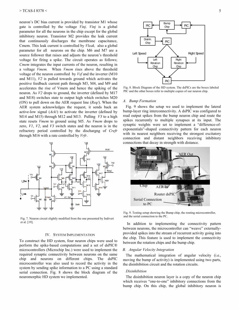
IV. SYSTEM IMPLEMENTATION To construct the HD system, four neuron chips were used to perform the spike-based computations and a set of dsPIC® microcontrollers (Microchip Inc.) were used to implement the required synaptic connectivity between neurons on the same chip and neurons on different chips. The dsPIC microcontroller was also used to record the activity in the system by sending spike information to a PC using a standard serial connection. Fig. 8 shows the block diagram of the neuromorphic HD system we implemented.
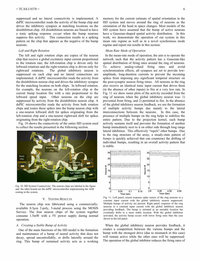
A. Bump Formation Fig. 9 shows the setup we used to implement the lateral
bump-layer ring interconnectivity. A dsPIC was configured to read output spikes from the bump neuron chip and route the spikes recurrently to multiple synapses at its input. The synaptic weights were set to implement a “difference-of-exponentials”-shaped connectivity pattern for each neuron with its nearest neighbors receiving the strongest excitatory connection and distant neighbors receiving inhibitory connections that decay in strength with distance.
In addition to implementing the connectivity pattern
between neurons, the microcontroller can “weave” externally-provided spikes into the stream of recurrent activity going into the chip. This feature is used to implement the connectivity between the rotation chips and the bump chip.
B. Angular Velocity Integration The mathematical integration of angular velocity (i.e.,
moving the bump of activity) is implemented using two parts, the disinhibition circuit and the rotation circuits.
Disinhibition The disinhibition neuron layer is a copy of the neuron chip
which receives “one-to-one” inhibitory connections from the bump chip. On this chip, the global inhibitory neuron is
Fig. 8. Block Diagram of the HD system. The dsPICs are the boxes labeledPIC and the other boxes refer to multiple copies of our neuron chip.
Fig. 9. Testing setup showing the Bump chip, the routing microcontroller, and the serial connection to the PC.
AER Out
AER In Bump Chip
Router dsPIC Serial Connection
to PC
Fig. 7. Neuron circuit slightly modified from the one presented by Indiveri et al. [19].
Ack/
Req/
V1 V2
V3
> TCAS-I 8378 <
6
suppressed and no lateral connectivity is implemented. A dsPIC microcontroller reads the activity of the bump chip and drives the inhibitory synapses at matching locations on the disinhibition chip. All disinhibition neurons are biased to have a tonic spiking response except when the bump neurons suppress this activity. This connection results in a spiking pattern on the chip that appears as the negative of the bump neurons.
Left and Right Rotation The left and right rotation chips are copies of the neuron
chip that receive a global excitatory input current proportional to the rotation rate; the left-rotation chip is driven only for leftward rotations and the right-rotation chip is driven only for rightward rotations. The global inhibitory neuron is suppressed on each chip and no lateral connections are implemented. A dsPIC microcontroller reads the activity from the disinhibition neuron chip and drives the inhibitory synapse for the matching location on both chips. In leftward rotation, for example, the neurons on the left-rotation chip at the current bump location fire with a rate proportional to the leftward speed input. Other neurons on the chip are suppressed by activity from the disinhibition neuron chip. A dsPIC microcontroller reads the activity from both rotation chips and routes these spikes into the bump neuron chip with a one-neuron leftward shift for spikes originating from the left-rotation chip and a one-neuron rightward shift for spikes originating from the right-rotation chip.
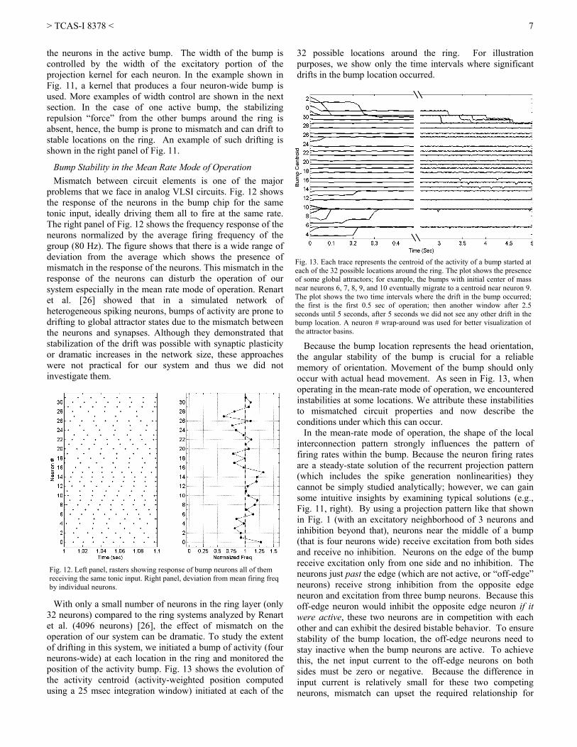
Fig. 10 shows the connectivity of the entire HD system used to collect the results presented in the following section.
V. TESTING RESULTS The neuron chip was fabricated using a commercially-
available 0.5μm 2-poly, 3-metal process using the MOSIS Service. The four neuron chips of the system together consume 1.5mW with a 5V power supply during normal operation.
A. Creating a Stable Bump of Activity One of the main functions of the HD model is the formation
and maintenance of a bump of neural activity that does not decay, spread uncontrollably, or drifts laterally around the ring. This bump of sustained activity acts as a working
memory for the current estimate of spatial orientation in the HD system and moves around the ring of neurons as the orientation of the head in space changes. Most models of the HD system have assumed that the bump of active neurons have a Gaussian-shaped spatial activity distribution. In this work, we demonstrate the operation of our system in this mean rate regime as well as in a novel synchronous mode regime and report our results in this section.
Mean Rate Mode of Operation In the mean-rate mode of operation, the aim is to operate the
network such that the activity pattern has a Gaussian-like spatial distribution of firing rates around the ring of neurons. To achieve analog-valued firing rates and avoid synchronization effects, all synapses are set to provide low-amplitude, long-duration currents to prevent the incoming spikes from imposing any significant temporal structure on the post-synaptic neuron firing times. All neurons in the ring also receive an identical tonic input current that drives them (in the absence of other inputs) to fire at a very low rate. In Fig. 11 we show raster plots of the activity recorded from the ring of neurons when the global inhibitory neuron was: 1) prevented from firing, and 2) permitted to fire. In the absence of the global inhibitory neuron feedback, we see the formation of multiple activity bumps due mainly to the lateral interconnections between the neurons. In this case, the presence of multiple bumps on the ring helps to stabilize the entire pattern. Due to the projection kernel, each bump actively sustains itself and prevents the formation of another bump immediately next to it on either side through long range lateral inhibition. This effectively “repels” other bumps. Due to the ring structure of the array, a steady-state pattern of bumps is quickly achieved that can counteract the drifting of individual bumps, resulting in an overall activity pattern that is stable.
When the global inhibitory neuron provides feedback, it
creates a competition between the various bumps and the bump with the strongest drive (due to mismatch in this case) will remain active while the other ones will be suppressed. The operation of the global inhibitor reduces the firing rates of
Fig. 10. HD System Connectivity: The neuron chips are labeled in the figure and the other boards are the dsPIC microcontroller implementing the AER routing in the system.
Fig. 11. Left panel, neural response spike rasters of the ring neurons to aconstant input current with the global inhibitory neuron suppressed.Multiple bumps of activity are present. Right panel; response of the ringneurons to a constant input current with the global inhibitory neuronproviding feedback. The bump is initiated at an unstable location buteventually drifts to a more stable location. With the global inhibitionactivated, the activity bump occurs with lower firing rates than the caseshown in the left panel.
> TCAS-I 8378 <
7
the neurons in the active bump. The width of the bump is controlled by the width of the excitatory portion of the projection kernel for each neuron. In the example shown in Fig. 11, a kernel that produces a four neuron-wide bump is used. More examples of width control are shown in the next section. In the case of one active bump, the stabilizing repulsion “force” from the other bumps around the ring is absent, hence, the bump is prone to mismatch and can drift to stable locations on the ring. An example of such drifting is shown in the right panel of Fig. 11.
Bump Stability in the Mean Rate Mode of Operation Mismatch between circuit elements is one of the major
problems that we face in analog VLSI circuits. Fig. 12 shows the response of the neurons in the bump chip for the same tonic input, ideally driving them all to fire at the same rate. The right panel of Fig. 12 shows the frequency response of the neurons normalized by the average firing frequency of the group (80 Hz). The figure shows that there is a wide range of deviation from the average which shows the presence of mismatch in the response of the neurons. This mismatch in the response of the neurons can disturb the operation of our system especially in the mean rate mode of operation. Renart et al. [26] showed that in a simulated network of heterogeneous spiking neurons, bumps of activity are prone to drifting to global attractor states due to the mismatch between the neurons and synapses. Although they demonstrated that stabilization of the drift was possible with synaptic plasticity or dramatic increases in the network size, these approaches were not practical for our system and thus we did not investigate them.
With only a small number of neurons in the ring layer (only
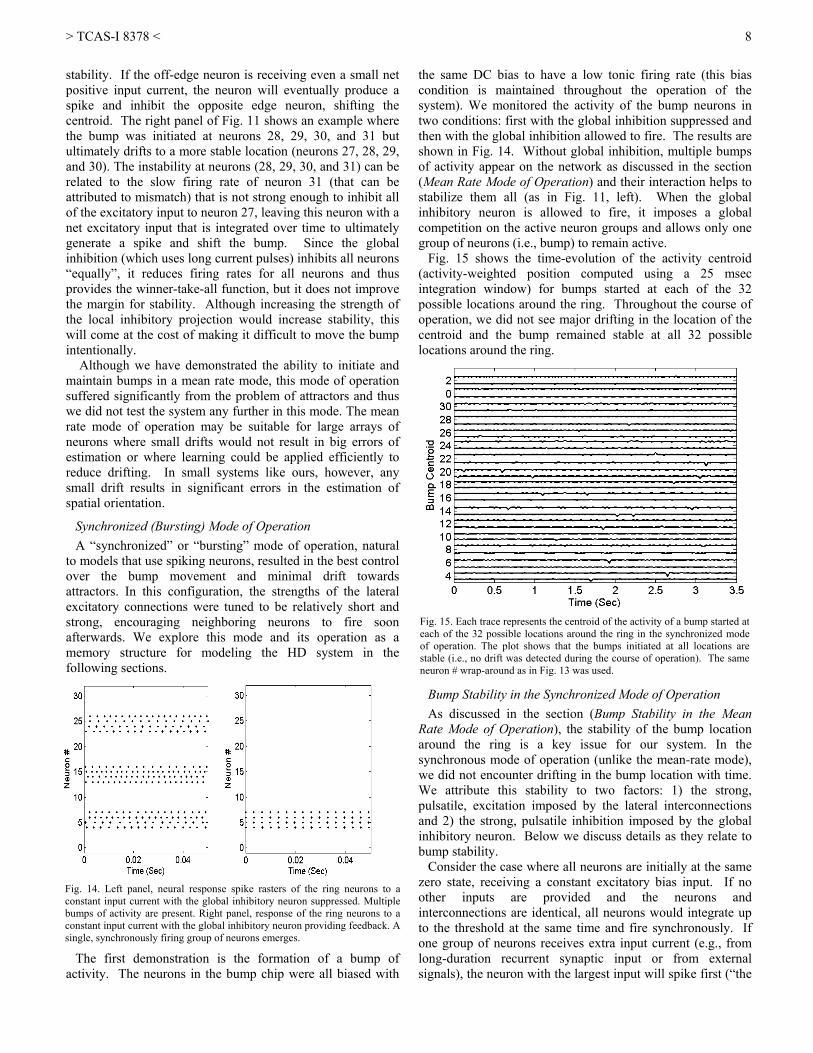
32 neurons) compared to the ring systems analyzed by Renart et al. (4096 neurons) [26], the effect of mismatch on the operation of our system can be dramatic. To study the extent of drifting in this system, we initiated a bump of activity (four neurons-wide) at each location in the ring and monitored the position of the activity bump. Fig. 13 shows the evolution of the activity centroid (activity-weighted position computed using a 25 msec integration window) initiated at each of the
32 possible locations around the ring. For illustration purposes, we show only the time intervals where significant drifts in the bump location occurred.
Because the bump location represents the head orientation,
the angular stability of the bump is crucial for a reliable memory of orientation. Movement of the bump should only occur with actual head movement. As seen in Fig. 13, when operating in the mean-rate mode of operation, we encountered instabilities at some locations. We attribute these instabilities to mismatched circuit properties and now describe the conditions under which this can occur.
In the mean-rate mode of operation, the shape of the local interconnection pattern strongly influences the pattern of firing rates within the bump. Because the neuron firing rates are a steady-state solution of the recurrent projection pattern (which includes the spike generation nonlinearities) they cannot be simply studied analytically; however, we can gain some intuitive insights by examining typical solutions (e.g., Fig. 11, right). By using a projection pattern like that shown in Fig. 1 (with an excitatory neighborhood of 3 neurons and inhibition beyond that), neurons near the middle of a bump (that is four neurons wide) receive excitation from both sides and receive no inhibition. Neurons on the edge of the bump receive excitation only from one side and no inhibition. The neurons just past the edge (which are not active, or “off-edge” neurons) receive strong inhibition from the opposite edge neuron and excitation from three bump neurons. Because this off-edge neuron would inhibit the opposite edge neuron if it were active, these two neurons are in competition with each other and can exhibit the desired bistable behavior. To ensure stability of the bump location, the off-edge neurons need to stay inactive when the bump neurons are active. To achieve this, the net input current to the off-edge neurons on both sides must be zero or negative. Because the difference in input current is relatively small for these two competing neurons, mismatch can upset the required relationship for
Fig. 13. Each trace represents the centroid of the activity of a bump started ateach of the 32 possible locations around the ring. The plot shows the presenceof some global attractors; for example, the bumps with initial center of massnear neurons 6, 7, 8, 9, and 10 eventually migrate to a centroid near neuron 9.The plot shows the two time intervals where the drift in the bump occurred;the first is the first 0.5 sec of operation; then another window after 2.5seconds until 5 seconds, after 5 seconds we did not see any other drift in thebump location. A neuron # wrap-around was used for better visualization ofthe attractor basins.
Fig. 12. Left panel, rasters showing response of bump neurons all of them receiving the same tonic input. Right panel, deviation from mean firing freq by individual neurons.
> TCAS-I 8378 <
8
stability. If the off-edge neuron is receiving even a small net positive input current, the neuron will eventually produce a spike and inhibit the opposite edge neuron, shifting the centroid. The right panel of Fig. 11 shows an example where the bump was initiated at neurons 28, 29, 30, and 31 but ultimately drifts to a more stable location (neurons 27, 28, 29, and 30). The instability at neurons (28, 29, 30, and 31) can be related to the slow firing rate of neuron 31 (that can be attributed to mismatch) that is not strong enough to inhibit all of the excitatory input to neuron 27, leaving this neuron with a net excitatory input that is integrated over time to ultimately generate a spike and shift the bump. Since the global inhibition (which uses long current pulses) inhibits all neurons “equally”, it reduces firing rates for all neurons and thus provides the winner-take-all function, but it does not improve the margin for stability. Although increasing the strength of the local inhibitory projection would increase stability, this will come at the cost of making it difficult to move the bump intentionally.
Although we have demonstrated the ability to initiate and maintain bumps in a mean rate mode, this mode of operation suffered significantly from the problem of attractors and thus we did not test the system any further in this mode. The mean rate mode of operation may be suitable for large arrays of neurons where small drifts would not result in big errors of estimation or where learning could be applied efficiently to reduce drifting. In small systems like ours, however, any small drift results in significant errors in the estimation of spatial orientation.
Synchronized (Bursting) Mode of Operation A “synchronized” or “bursting” mode of operation, natural
to models that use spiking neurons, resulted in the best control over the bump movement and minimal drift towards attractors. In this configuration, the strengths of the lateral excitatory connections were tuned to be relatively short and strong, encouraging neighboring neurons to fire soon afterwards. We explore this mode and its operation as a memory structure for modeling the HD system in the following sections.
The first demonstration is the formation of a bump of
activity. The neurons in the bump chip were all biased with
the same DC bias to have a low tonic firing rate (this bias condition is maintained throughout the operation of the system). We monitored the activity of the bump neurons in two conditions: first with the global inhibition suppressed and then with the global inhibition allowed to fire. The results are shown in Fig. 14. Without global inhibition, multiple bumps of activity appear on the network as discussed in the section (Mean Rate Mode of Operation) and their interaction helps to stabilize them all (as in Fig. 11, left). When the global inhibitory neuron is allowed to fire, it imposes a global competition on the active neuron groups and allows only one group of neurons (i.e., bump) to remain active.
Fig. 15 shows the time-evolution of the activity centroid (activity-weighted position computed using a 25 msec integration window) for bumps started at each of the 32 possible locations around the ring. Throughout the course of operation, we did not see major drifting in the location of the centroid and the bump remained stable at all 32 possible locations around the ring.
Bump Stability in the Synchronized Mode of Operation As discussed in the section (Bump Stability in the Mean
Rate Mode of Operation), the stability of the bump location around the ring is a key issue for our system. In the synchronous mode of operation (unlike the mean-rate mode), we did not encounter drifting in the bump location with time. We attribute this stability to two factors: 1) the strong, pulsatile, excitation imposed by the lateral interconnections and 2) the strong, pulsatile inhibition imposed by the global inhibitory neuron. Below we discuss details as they relate to bump stability.
Consider the case where all neurons are initially at the same zero state, receiving a constant excitatory bias input. If no other inputs are provided and the neurons and interconnections are identical, all neurons would integrate up to the threshold at the same time and fire synchronously. If one group of neurons receives extra input current (e.g., from long-duration recurrent synaptic input or from external signals), the neuron with the largest input will spike first (“the
Fig. 14. Left panel, neural response spike rasters of the ring neurons to aconstant input current with the global inhibitory neuron suppressed. Multiplebumps of activity are present. Right panel, response of the ring neurons to aconstant input current with the global inhibitory neuron providing feedback. Asingle, synchronously firing group of neurons emerges.
Fig. 15. Each trace represents the centroid of the activity of a bump started ateach of the 32 possible locations around the ring in the synchronized modeof operation. The plot shows that the bumps initiated at all locations arestable (i.e., no drift was detected during the course of operation). The sameneuron # wrap-around as in Fig. 13 was used.
> TCAS-I 8378 <
9
winning neuron”) and it will provide a strong excitatory pulse of current to its nearest neighbors and a strong inhibitory pulse of current to its more-distant neighbors. The strong lateral excitatory projection dramatically accelerates the winning neuron’s excitatory neighborhood, producing a group of near-synchronous spikes while strongly inhibiting (i.e., slowing down or resetting) the off-edge neurons. When the synchronous group fires spikes, they excite the global inhibitory neuron to fire its spike very shortly after the active bump neurons. Because the inhibition arrives while the active neurons are still in their refractory period, this inhibition does not affect their firing rate. For non-firing neurons, however, this strong inhibitory pulse resets their membrane potential to zero.
A byproduct of the synchronous mode is that the neurons will have identically high firing rates. In the synchronous mode, the first neuron to fire excites its six nearest neighbors. The second neuron to fire (ideally one of the first neuron’s direct neighbors) further excites the neighborhood, but suppresses neurons four locations away. Ultimately a group of four neurons will fire that do not receive any inhibition. By providing sufficiently strong local inhibition, we can ensure that the off-edge neurons never fire, to ensure stability. Because this inhibition is short, it is unlikely to interfere with other external inputs that direct the intentional movement of the bump. This feature is important because it creates a larger parameter space over which stability is created without negative consequences for movement. Furthermore, the four active neurons excite the global inhibitory neuron with a short latency such that the global inhibitory pulse can provide additional inhibition that also benefits stability without interfering with movements of the bump. Once the refractory period is over and the global inhibition has passed, all neurons begin integrating again towards threshold to start a new cycle.
In this scheme, the global inhibitory neuron plays two roles: it discourages multiple bumps around the ring and it resets all neurons to their zero state after the bump neurons have fired a spike, erasing any residual charge in the “non-bump” neurons due to mismatch and preventing these “non-bump” neurons from firing over time.
B. Controlling the Bump Width In the previous experiment we showed the emergence of a
four-neuron-wide bump as a result of the local connectivity between the neurons and global inhibitor. The width is controlled by adjusting the span of the lateral excitatory-inhibitory projection pattern between the neurons in the ring; wider projections produce a wider bump and narrow projections produce narrow bumps. In Fig. 16 we show three different examples of widths obtained by changing the recurrent projection pattern width.
One interesting property of the synchronous case is that the firing rate of the group is largely locked to the most active neuron in the group. Wider bump widths, therefore, result in fewer neurons determining the bump firing rates thus reducing the variability seen around the ring.
C. System Data
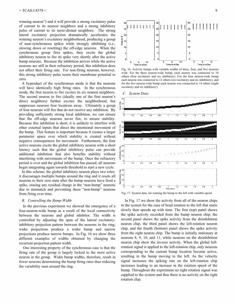
In Fig. 17 we show the activity from all of the neuron chips
in the system for the case of head rotation to the left that starts slowly then speeds up with time. The first (top) panel shows the spike activity recorded from the bump neuron chip, the second panel shows the spike activity from the disinhibition neuron chip, the third panel shows the left-rotation neuron chip, and the fourth (bottom) panel shows the spike activity from the right neuron chip. The bump is initially stationary at neurons 8, 9, 10, and 11, while neurons on the disinhibition neuron chip show the inverse activity. When the global left-rotation signal is applied to the left-rotation chip, only neurons corresponding to the current bump location become active, resulting in the bump moving to the left. As the velocity signal increases the spiking rate on the left-rotation chip increases leading to an increase in the rotation speed of the bump. Throughout the experiment no right rotation signal was supplied to the system and thus there is no activity on the right rotation chip.
Fig. 16. Activity bumps with variable widths of three, four, and five neurons wide. For the three neuron-wide bump, each neuron was connected to 10 others (four excitatory and six inhibitory). For the four neuron-wide bump each neuron was connected to 12 others (six excitatory and six inhibitory), and for the five neuron-wide bump each neuron was connected to 14 others (eight excitatory and six inhibitory).
Fig. 17. System data, for rotating the bump to the left with variable speed.
> TCAS-I 8378 <
10
D. Moving the Bump
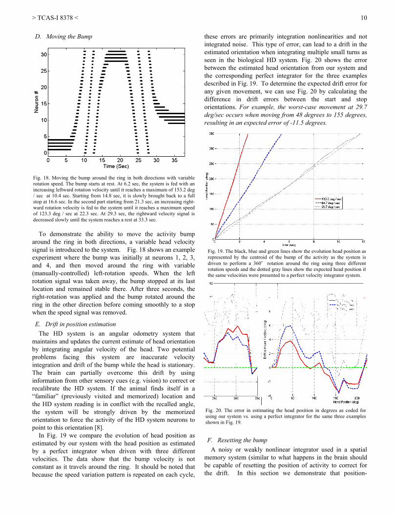
To demonstrate the ability to move the activity bump
around the ring in both directions, a variable head velocity signal is introduced to the system. Fig. 18 shows an example experiment where the bump was initially at neurons 1, 2, 3, and 4, and then moved around the ring with variable (manually-controlled) left-rotation speeds. When the left rotation signal was taken away, the bump stopped at its last location and remained stable there. After three seconds, the right-rotation was applied and the bump rotated around the ring in the other direction before coming smoothly to a stop when the speed signal was removed.
E. Drift in position estimation The HD system is an angular odometry system that
maintains and updates the current estimate of head orientation by integrating angular velocity of the head. Two potential problems facing this system are inaccurate velocity integration and drift of the bump while the head is stationary. The brain can partially overcome this drift by using information from other sensory cues (e.g. vision) to correct or recalibrate the HD system. If the animal finds itself in a “familiar” (previously visited and memorized) location and the HD system reading is in conflict with the recalled angle, the system will be strongly driven by the memorized orientation to force the activity of the HD system neurons to point to this orientation [8].
In Fig. 19 we compare the evolution of head position as estimated by our system with the head position as estimated by a perfect integrator when driven with three different velocities. The data show that the bump velocity is not constant as it travels around the ring. It should be noted that because the speed variation pattern is repeated on each cycle,
these errors are primarily integration nonlinearities and not integrated noise. This type of error, can lead to a drift in the estimated orientation when integrating multiple small turns as seen in the biological HD system. Fig. 20 shows the error between the estimated head orientation from our system and the corresponding perfect integrator for the three examples described in Fig. 19. To determine the expected drift error for any given movement, we can use Fig. 20 by calculating the difference in drift errors between the start and stop orientations. For example, the worst-case movement at 29.7 deg/sec occurs when moving from 48 degrees to 155 degrees, resulting in an expected error of -11.5 degrees.
F. Resetting the bump A noisy or weakly nonlinear integrator used in a spatial
memory system (similar to what happens in the brain should be capable of resetting the position of activity to correct for the drift. In this section we demonstrate that position-
Fig. 18. Moving the bump around the ring in both directions with variablerotation speed. The bump starts at rest. At 6.2 sec, the system is fed with anincreasing leftward rotation velocity until it reaches a maximum of 153.2 deg/ sec at 10.4 sec. Starting from 14.8 sec, it is slowly brought back to a fullstop at 16.6 sec. In the second part starting from 21.3 sec, an increasing right-ward rotation velocity is fed to the system until it reaches a maximum speedof 123.3 deg / sec at 22.3 sec. At 29.3 sec, the rightward velocity signal isdecreased slowly until the system reaches a rest at 33.3 sec.
Fig. 19. The black, blue and green lines show the evolution head position as represented by the centroid of the bump of the activity as the system is driven to perform a 360˚ rotation around the ring using three different rotation speeds and the dotted gray lines show the expected head position if the same velocities were presented to a perfect velocity integrator system.
Fig. 20. The error in estimating the head position in degrees as coded for using our system vs. using a perfect integrator for the same three examplesshown in Fig. 19.
> TCAS-I 8378 <
11
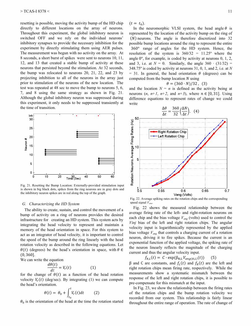
resetting is possible, moving the activity bump of the HD chip directly to different locations on the array of neurons. Throughout this experiment, the global inhibitory neuron is switched OFF and we rely on the individual neurons’ inhibitory synapses to provide the necessary inhibition for the experiment by directly stimulating them using AER pulses. The measurement was begun with no activity on the array. At 8 seconds, a short burst of spikes were sent to neurons 10, 11, 12, and 13 that created a stable bump of activity at these neurons that persisted beyond the stimulation. At 32 seconds, the bump was relocated to neurons 20, 21, 22, and 23 by projecting inhibition to all of the neurons in the array just prior to stimulation of the neurons of the new location. The test was repeated at 48 sec to move the bump to neurons 5, 6, 7, and 8 using the same strategy as shown in Fig. 21. Although the global inhibitory neuron was suppressed during this experiment, it only needs to be suppressed transiently at the time of transition.
G. Characterizing the HD System The ability to create, sustain, and control the movement of a
bump of activity on a ring of neurons provides the desired infrastructure for creating an HD system. This system acts by integrating the head velocity to represent and maintain a memory of the head orientation in space. For this system to act as an integrator of head velocity, it is important to control the speed of the bump around the ring linearly with the head rotation velocity as described in the following equations. Let
(degrees) be the head’s orientation in space, with 0, 360 .
We can write the equation
1
for the change of as a function of the head rotation velocity (deg/sec). By integrating (1) we can compute the head’s orientation.
2
is the orientation of the head at the time the rotation started
. In the neuromorphic VLSI system, the head angle is
represented by the location of the activity bump on the ring of neurons. The angle is therefore discretized into 32 possible bump locations around the ring to represent the entire 360° range of angles for the HD system. Hence, the resolution of the system is 360/32 = 11.25º where the angle 0°, for example, is coded by activity at neurons 0, 1, 2, and 3, i.e. at N = 0. Similarly, the angle 360 · (31/32) = 348.75º is coded by activity at neurons 31, 0, 1, and 2, i.e. at N = 31. In general, the head orientation (degrees) can be computed from the bump location using
360 /32 , 3 and the location N = n is defined as the activity being at neurons (n, n+1, n+2, and n+3), where 0, 31 . Using difference equations to represent rates of change we could write
ΔΔ
36032
ΔΔ . 4
Fig. 22 shows the measured relationship between the
average firing rate of the left- and right-rotation neurons on each chip and the bias voltage Vang (volts) used to control the Vinj bias of the left and right rotation chips. The angular velocity input is logarithmically represented by the applied bias voltage Vang that controls a charging current of a rotation neuron, driving it to fire spikes. Because the current is an exponential function of the applied voltage, the spiking rate of the neuron linearly reflects the magnitude of the charging current and thus the angular velocity input.
, · exp βR,L , 5 β and C are constants, and and are the left and right rotation chips mean firing rate, respectively. While the measurements show a systematic mismatch between the response of the left and right rotation chips, it is possible to pre-compensate for this mismatch at the input.
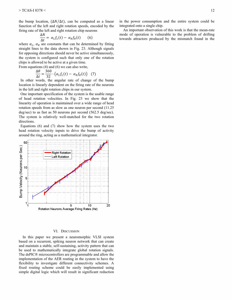
In Fig. 23, we show the relationship between the firing rates of the rotation chips and the bump rotation velocity we recorded from our system. This relationship is fairly linear throughout the entire range of operation. The rate of change of
Fig. 21. Resetting the Bump Location: Externally-provided stimulation inputis shown in big black dots, spikes from the ring neurons are in gray dots andthe inhibitory neuron spikes are in red along the top of the graph.
Fig. 22. Average spiking rates on the rotation chips and the corresponding speed signal Vang.
> TCAS-I 8378 <
12
the bump location, Δ Δ⁄ , can be computed as a linear function of the left and right rotation speeds, encoded by the firing rate of the left and right rotation chip neurons
ΔΔ 6
where , are constants that can be determined by fitting straight lines to the data shown in Fig. 23. Although signals for opposing directions should never be active simultaneously, the system is configured such that only one of the rotation chips is allowed to be active at a given time. From equations (4) and (6) we can also write,
ΔΔ
36032 · 7
In other words, the angular rate of change of the bump location is linearly dependent on the firing rate of the neurons in the left and right rotation chips in our system. One important specification of the system is the usable range
of head rotation velocities. In Fig. 23 we show that the linearity of operation is maintained over a wide range of head rotation speeds from as slow as one neuron per second (11.25 deg/sec) to as fast as 50 neurons per second (562.5 deg/sec). The system is relatively well-matched for the two rotation directions. Equations (6) and (7) show how the system uses the two
head rotation velocity inputs to drive the bump of activity around the ring, acting as a mathematical integrator.
VI. DISCUSSION In this paper we present a neuromorphic VLSI system
based on a recurrent, spiking neuron network that can create and maintain a stable, self-sustaining, activity pattern that can be used to mathematically integrate global rotation signals. The dsPIC® microcontrollers are programmable and allow the implementation of the AER routing in the system to have the flexibility to investigate different connectivity schemes. A fixed routing scheme could be easily implemented using simple digital logic which will result in significant reduction
in the power consumption and the entire system could be integrated onto a single chip.
An important observation of this work is that the mean-rate mode of operation is vulnerable to the problem of drifting towards attractors produced by the mismatch found in the
> TCAS-I 8378 <
13
Computational Hypothesis’, Journal of Cognitive Neuroscience, 1991, 3, (2), pp. 190-203 [13] Zhang, K.: ‘Representation Of Spatial Orientation By The Intrinsic Dynamics Of The Head-Direction Cell Ensemble: A Theory’, The Journal Of Neuroscience, 1996, 16, (6), pp. 2112-2126 [14] Redish, A.D., Elga, A.N., and Touretzky, D.S.: ‘A Coupled Attractor Model Of The Rodent Head Direction System’, Network: Computation in Neural Systems, 1996, 7, (4), pp. 671-685 [15] P. Song and X. J. Wang, "Angular Path Integration By Moving "Hill Of Activity": A Spiking Neuron Model Without Recurrent Excitation Of The Head-Direction System," The Journal of neuroscience : the official journal of the Society for Neuroscience, vol. 25, pp. 1002-1014, 2005. [16] T. Degris, et al., "A spiking neuron model of head-direction cells for robot orientation," in The Eighth International Conference on Simulation of Adaptive Behavior, From Animals to Animats, 2004, pp. 255-263. [17] P. Stratton, et al., "Automatic Calibration of a Spiking Head-Direction Network for Representing Robot Orientation," presented at the Australian Conference on Robotics and Automation, Sydney, Australia, 2009. [18] Massoud, T.M., and Horiuchi, T.K.: ‘A Neuromorphic Head Direction Cell System’. Proc. IEEE International Symposium for Circuits and Systems (ISCAS 2009), Taipei, Taiwan2009 [19] Laing, C., and Chow, C.: ‘Stationary bumps in networks of spiking neurons.’, Neural Comput, 2001, 13, (7), pp. 1473-1494 [20] Vogels, T.P., Rajan, K., and Abbott, L.F.: ‘Neural network dynamics’, Annu Rev Neurosci, 2005, 28, pp. 357-376 [21] Trappenberg, T.P., and Standage, D.I.: ‘Multi-packet regions in stabilized continuous attractor networks’, Neurocomputing, 2004, 65-66, pp. 617-622 [22] Basso, M.A., and Wurtz, R.H.: ‘Neuronal activity in substantia nigra pars reticulata during target selection’, Journal of Neuroscience, 2002, 22, (5), pp. 1883-1894 [23] Indiveri, G., Chicca, E., and Douglas, R.J.: ‘A VLSI Array Of Low-Power Spiking Neurons And Bistable Synapses With Spike-Timing Dependent Plasticity’, Neural Networks, IEEE Transactions on, 2006, 17, (1), pp. 211-221 [24] Boahen, K.A.: ‘Point-To-Point Connectivity Between Neuromorphic Chips Using Address Events’, Circuits and Systems II: Analog and Digital Signal Processing, IEEE Transactions on, 2000, 47, (5), pp. 416-434 [25] Arthur J. V. and Boahen K,: ‘Silicon Neurons that Inhibit to Synchronize’, Proc. IEEE International Symposium for Circuits and Systems (ISCAS 2006), Island of Kos, Greece 2006 [26] Renart, A., Song, P.C., and Wang, X.J.: ‘Robust spatial working memory through homeostatic synaptic scaling in heterogeneous cortical networks’, Neuron, 2003, 38, (3), pp. 473-485 [27] Sridharan D, Millner S, Arthur J and Boahen K (2010). Robust spatial working memory through inhibitory gamma synchrony. Conference Abstract: Computational and systems neuroscience 2010. doi: 10.3389/conf.fnins.2010.03.00012 Tarek M. Massoud (SM’99–M’08) received his B.Sc. (2001) and M.Sc. (2004) in Electrical Engineering from Alexandria University, Alexandria, Egypt. In 2005, he joined the Computational Sensorimotor Systems Laboratory, at the University of Maryland where he is currently working toward his Ph.D. degree. His general research interests are analog very large-scale integration (VLSI) and computational neuroscience Timothy K. Horiuchi (M’89) received both his B.S. in Electrical Engineering (1989) and Ph.D. in Computation and Neural Systems (1997) from the California Institute of Technology. He worked as a postdoctoral scholar at the Johns Hopkins University until moving to the University of Maryland in 1999. He is currently an Associate Professor in the Electrical and Computer Engineering Department and the Institute for Systems Research at the University of Maryland, College Park. His main research interests are in the design and fabrication of neuromorphic VLSI circuits and the implementation of neural computation in silicon. His primary focus has been on the modeling of spike-based neural processing models of the auditory system of the echolocating bat.

General Response to reviewers: (Our responses are shown in bold) In response to the reviewers’ comments, we have made many large and small changes to the paper to improve both clarity and thoroughness. The largest, most significant changes are the following: We added a new figure, (figure 7), a schematic of the neuron circuit we are using, and a new subsection to explain how the circuit works. We recollected some of the data in our system showing a cleaner response for the mean rate region of operation and have included a new figure (figure 12) that characterizes the mismatch in the response of the bump neurons. We added a new subsection to the testing results where we show examples of the error in the velocity integration process compared to a perfect integrator. Reviewers' and Associate Editor's Comments ========================================== Editor’s Recommendation: Resubmit after Minor Revision for Review as a Regular Paper Comments to the Author Key references that must be included: ‐‐‐‐‐‐‐‐‐‐‐‐‐‐‐‐‐‐‐‐‐‐‐‐‐‐‐‐‐‐‐‐‐‐‐‐‐ Review Number 1. ***************** Comments to the Author ‐‐‐‐‐‐‐‐‐‐‐‐‐‐‐‐‐‐‐‐‐‐ General comments: The manuscript presents a novel vlsi circuit implementing the functionality of the head‐direction system. A novel feature of this work is the mechanism for moving the activity bump on the ring of head‐direction cells proportionally to the velocity of the head rotation movement. The VLSI circuit implements 32 HD integrate and fire neuron circuits with programmable excitatory/inhibitory synapses to control the width of the activity bump. Additional neurons are used for integrating head rotation movements. Experiments test the stability of activity bump. In mean‐rate mode, the bumps drift due to circuit mismatches, while in spiking‐mode the drift problem is resolved due to the synchronized mode of operation. Also, results show that the activity bump moves proportionally with the rotation speed. Specific comments: Section I and II. Please refer to more recent papers that implement spiking neural models of head‐direction systems. How does your model relate to those? We have added a discussion about how our model relates to other models. Section II. Compare the novel approach of moving the activity bump with head rotation with that used in other models. What is different, why is this better approach. We have added a comparison between our model and previously proposed models.

B. Second paragraph is identical with the first paragraph. Fixed. Figure 4. The light gray connections are not visible. The figure has been redrawn for clarity. Section III. Paragraph 2, correct inhibitor neuron. Fixed. Section V A. In Figure 11 it seems that the drift is bigger and occurs mostly on the centroids on the top and bottom parts of the plot, but not on the centroids in the middle (centroids numbered 12 to 24). Can you explain this? At first glance, the centroids all appear to drift in towards the center of the array, however, we have plotted the graph with positions 0, 1, & 2 wrapped around to sit up near position 31. So, in fact, positions 4 - 13 have a tendency to drift inward towards the center and positions 0 – 2 drift outward. On the other side, positions 31-29 drift towards the center. While we do expect transistor fabrication mismatch to produce a systematic asymmetry on both the edges, the reversal in drift direction at position 2 suggests that the increased drift at the edges is not due to a simple edge effect explanation. D. Figure 16 should be complemented with the rotation/speed information. Added to the figure (now figure 18). If possible, add results on the error that accumulates over time due to inaccurate integration of velocity. We have added a new subsection to the results section (Section V) where we present data from our system showing the error in the velocity integration process. E. On Figure 17, the inhibitory neuron spikes are not visible. Please redraw the activity of the inhibitory neuron, preferably on a different figure. In this experiment (now Fig 21), the feedback global inhibition is not present. We are using only the local inhibition to maintain the bump. Here we simply demonstrate that it is possible to move the bump from one location to another through a reset procedure. At the time of reset, we send an inhibitory spike to all neurons prior to sending the excitatory burst to the new location. The time of the inhibition is shown at the top of the graph (in red). We have added some text to try to make this clearer. Missing Key References: Missing more recent references: Angular Path Integration by Moving "Hill of Activity": A Spiking Neuron Model without Recurrent Excitation of the Head‐Direction System, Pengcheng Song and Xiao‐Jing Wang, Journal of Neuroscience, January 26, 2005 Xiaohui Xie, Richard H. R. Hahnloser, and H. Sebastian Seung Double‐ring network model of the head‐direction system, Phys. Rev. E 66, 041902 (2002) Michakl B. Zugaro, Angelo Arleo, Alain Berthoz, and Sidney I. Wiener Rapid Spatial Reorientation

and Head Direction Cells, The Journal of Neuroscience, April 15, 2003, 23(8):3478 Review Number 2. ***************** Comments to the Author ‐‐‐‐‐‐‐‐‐‐‐‐‐‐‐‐‐‐‐‐‐‐ This is a nice piece of work that extends the authors' previous conference proceeding by characterizing the effects of mismatch and synchronization on bump stability in a neuromorphic implementation of a head‐direction‐cell system. It is generally well‐written and organized in a logical narrative. There is something vaguely unsatisfying from the perspective of wasted power in that the system seems to require a number of neurons to be firing full tilt even when nothing is changing. But I suppose this is really a complaint about the biology, not the engineering. Yes! Disinhibition through tonic inhibition is present in a few places in the brain and raises the incredibly interesting question of how evolution can justify this energy expenditure. In this proposed model, we use disinhibition as a signal gate, allowing a clean separation between the bump neurons’ spiking rates and the velocity neurons’ spiking rates (versus coincidence models) The wasted spiking power is a byproduct of the biologically-inspired mechanism we are adopting for implementing the head direction cell system. When it is clear what mechanism is truly at work in the biological network, we update this model. While we can modulate the power consumption of the system by controlling the spiking rate of the disinhibition layer neurons, the firing rate we currently use is set to be a reasonable compromise between power consumption and responsiveness to velocity commands. A more abstracted engineering model might simply replace this with a logic HIGH (instead of active spiking), drawing no more energy than a logic LOW. It does seem like the pulse‐extending synapse circuit has about twice as many transistors and capacitors as it needs. Why does it take three bias voltages and two capacitors to stretch a pulse? Couldn't you achieve the same effect with just C2 and M5‐M11 (plus or minus an inverter for the Ack signal)? Thanks for pointing to us your comments regarding the second stage in the synapse circuit, we understand that the design can work with only one stage and we may move to that design in future work, but in this work we opted to use this design to have a little more control over the shape of the EPSC / IPSC to ensure proper operation of the system. Minor copyedits: Thanks for pointing to us the editorial comments; we have applied the modifications suggested.
Figure 11: The neuron location ticks on the y‐axis do not line up with the corresponding centroid position traces. In Fig. 11 (now Fig. 13), the ticks are not expected to line up with the centroid of the bump because we are using a four-neuron-wide bump. (e.g., a bump at 1, 2, 3, and 4 would be marked as 2.5). Also, since we are operating in a mean rate mode, the centroid is a bit jittery and this jitter is also affected by the temporal averaging window used to compute the centroid.

Is there a reference that describes the circuit controlled by V_{ang}? Vang is controlling the gate of a pfet transistor operating in the subthreshold region of operation to logarithmically encode the Vang voltage to a current and pushes it into the membrane capacitance of all neurons in the left or right rotation chip. We have added a few more circuit details in the text. We have added a new subsection to describe the neuron circuit we are using and we added some test in the analysis section to relate Vang to the appropriate bias in the circuit. Review Number 3. ***************** Comments to the Author ‐‐‐‐‐‐‐‐‐‐‐‐‐‐‐‐‐‐‐‐‐‐ The authors present a neuromorphic system that implements a quasi‐continuous attractor memory of head direction, and a mechanism for its shift based on velocity information, the latter being an element of novelty of the work. The reported work is interesting and certainly suited for the target journal. The manuscript is well written and clear, and the reader is guided through thoroughly explained analysis steps motivating the design choices made by the authors. Though I have some reservations about some statements of biological inspiration and also on the computational relevance of the extremely simple proposed architecture, I will refrain from addressing this general issues, which are ultimately for the scientific community to evaluate, and will limit my comments/questions to technical issues. page 3, 2nd column, just before fig.4: '... which moves the bump one location to the left.' I see this in the simple example shown in fig.4, and I see in the general case that one more neuron to the left is activated, but the inactivation of the one on the right should depend on some balance between the width of the excitatory of the Mexican hat synaptic kernel and the strength of the shared inhibition implementing the soft WTA, and the inhibition at the periphery of the synaptic kernel: am I missing some self‐evident features or more explanation is appropriate? We noticed that we were quite vague in explaining the mechanism of the bump movement and we have included some more explanation. page 4, 2nd column, 'an output current pulse on he order of a few ms for each AER spike': I wonder if any analysis has been made concerning the constrains imposed by a negligible collision probability between two incoming AER events, given the pulse duration. I see this might not be a hard problem for regular spikes, but it might be in the more general, and realistic, case of irregular firing. (this remark could also be relevant to the description of 'mean rate mode' at the end of page 5). It is a little unclear what you mean by collision, however, we can address two forms of collision that you may be referring to. On the receiving side of an arbitrated AER bus, collisions do not occur because they have already been resolved either at the transmitter’s arbiter or en route. This does mean that AER spikes may arrive sequentially with sub-
microsecond separation. By extending a short AER spike into a milliseconds-long current pulse, the question becomes what happens to a subsequent AER spikes if they arrive before the current pulse terminates? The pulse extender circuit (very roughly) “linearly” extends the duration of the pulse with each AER spike until maximum pulse duration is reached. Could the authors say a few more words on the impact of mismatch (discussed extensively at page 6 in relation to bump drift) on the firing of neurons? For example, how much tuning is needed to implement a Gaussian‐like spatial distribution in ‘mean rate mode'? We have included a new figure showing the effect of mismatch of the firing of the neurons in the bump chip. In fig. 11, it seems that a bump started near 8 dies out at about 1.4 sec. Since, I understand, each trace is the position in time of the centroid of a bump in the absence of other bumps, I see how it can drift, but that one seems a strange occurrence. You are absolutely correct. Fig 11 (now Fig 13) showed experimental data from of a parameter set that produced an occasional loss of the bump at that location. This was a mistake on our part. We have replaced the figure with data from a parameter set that functions properly in extended testing. Concerning the section on synchronized mode, some readers might find misleading to equate this to a 'bursting' mode (and I am skeptical that it is to be deemed 'natural' for networks of spiking neurons). Anyway, how much is this mode different from having just one self‐exciting neuron, in the WTA ring, coding for each head direction, given the flat firing rate distribution among neurons in the 'attractor'? Indeed, a general remark is that a stable pattern of activity is just one of the features defining an attractor state; I don't see (at least for the synchronized regime) the real advantage of a 'population' representation. May the authors comment on this? Having more than one active neuron in the bump circuit in the synchronized mode does not add any additional benefit in coding the position than having one active neuron. The real benefit of having multiple active neurons in the bump is that the synchronization helps in reducing the variability in the firing rates between the individual neurons due to mismatch, since in the bump the active neurons are driven to fire at the same rate as the fastest neuron due to the strong lateral excitatory projection. As we report in the paper we have operated the system using various configurations; 3-, 4-, and 5-neuron bumps have been tested and our results suggest that as the active bump gets wider, less variability of the firing rates of the neurons is seen. page 7, 2nd column, bottom: '... the inhibition arrives while the active neurons are still in their refractory period...': does this imply a strong constraint on the inhibitory pulse duration? Yes, the excitatory pulses must outlast both the global inhibitory and local inhibitory pulses for the bumps to be self-sustaining.