analog vlsi neuromorphic network with programmable membrane
TRANSCRIPT
Analog VLSI Neuromorphic Network withProgrammable Membrane Channel Kinetics
Theodore Yu1,2,4 and Gert Cauwenberghs2,3,4
1 Electrical and Computer Engineering Department, Jacobs School of Engineering2 Neurobiology Section, Division of Biological Sciences
3 Bioengineering Department, Jacobs School of Engineering4 Institute for Neural Computation
University of California San Diego, La Jolla, CA 92093
Abstract—We demonstrate neuron spiking dynamics in a smallnetwork of analog silicon neurons with dynamical conductance-based synapses. The analog VLSI chip (NeuroDyn) emulates ana-log continuous-time dynamics in a fully digitally programmablenetwork of 4 biophysical neurons. Each neuron in NeuroDynimplements Hodgkin-Huxley dynamics in 4 variables, with 28parameters defining the conductances, reversal potentials, andvoltage-dependence of the channel kinetics. All 12 chemicalsynapses interconnecting the neurons also have individually pro-grammable parameters defining conductance, reversal potential,and pre/post-synaptic voltage dependence of the channel kinetics.All configurable parameters in the implemented model have abiophysical origin, thus supporting direct interpretation of theresults of adapting/tuning the parameters in terms of neurobi-ology. Uniform temporal scaling of the dynamics of membraneand gating variables is demonstrated by tuning a single currentparameter, yielding variable speed output exceeding real time.The 0.5µm CMOS chip measures 3mm × 3mm, and consumes1.29 mW.
I. INTRODUCTION
Neuromorphic engineering [1] takes inspiration from neuro-biology in the design of artificial neural systems in silicon inte-grated circuits, based upon function and structural organizationof biological nervous systems. Investigation of neural behavioron large scale requires modeling and implementation of indi-vidual neurons and their synaptic connections. Hodgkin andHuxley’s seminal work in the investigation and formalizationof neuron dynamics have long been the standard of biophysicalaccuracy [2]. However, the primary drawback of the Hodgkinand Huxley formalism is the difficulty of implementing thevast number of parameters and the resulting complexity.Previous hardware implementations of neurons and synapsesare typically limited to static modeling in an integrate-and-fire framework. Though this approach is generally convenientand computationally efficient, passive modeling of the currentsnot only lacks insight from biological structure, but alsolacks accuracy in modeling the timing of the postsynapticaction potentials. Several integrated circuit implementationsof Hodgkin-Huxley neurons have been formulated and demon-strated [3], [4], [5], [6], [7] and [8]. Here we present a networkof Hodgkin-Huxley neurons and conductance-based synapsesthat accurately models the detailed rate-based kinetics ofmembrane channels in the neural and synaptic dynamics.
V4
s1,2
s2,1
s3,4
s4,3
s4,2
s2,4
s3,1
s1,3
s1,4
s3,2 s2,3
s4,1
V2
V3
V1
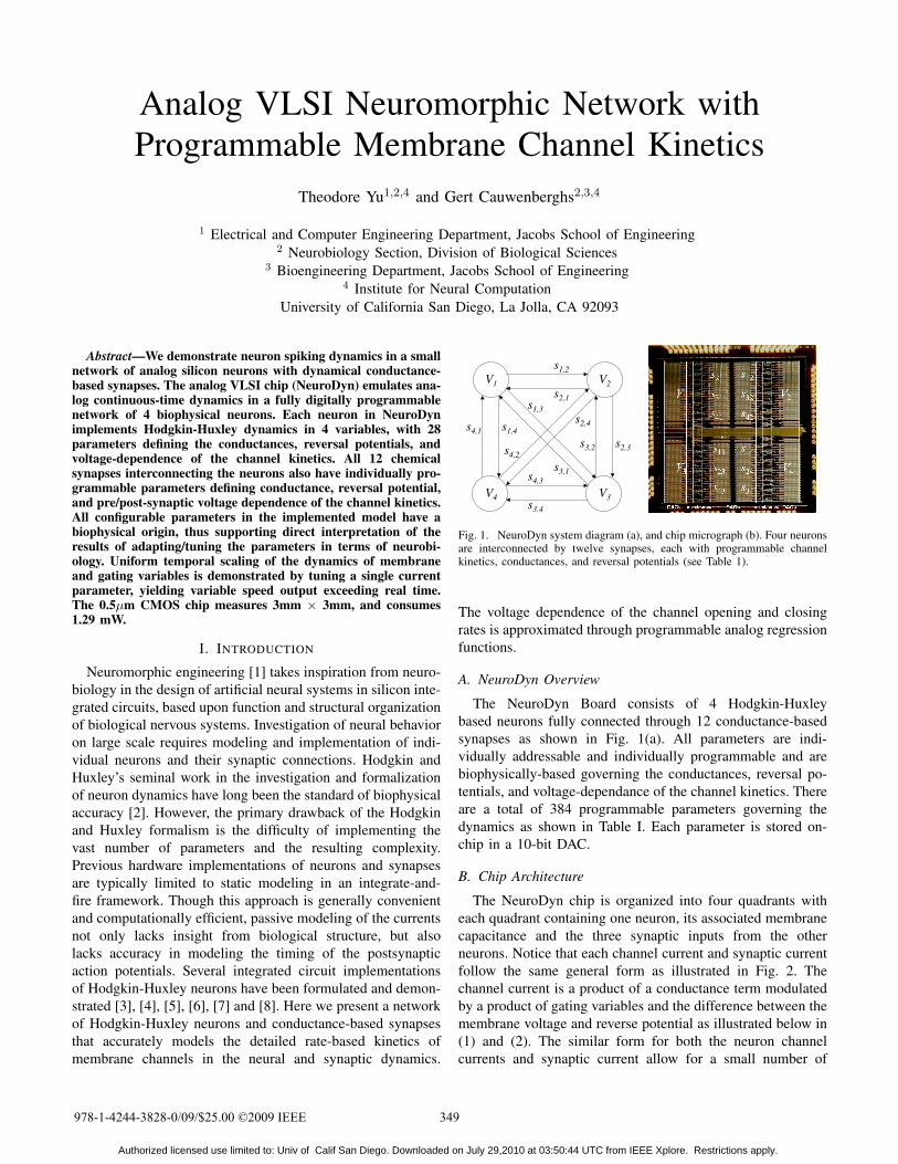
Fig. 1. NeuroDyn system diagram (a), and chip micrograph (b). Four neuronsare interconnected by twelve synapses, each with programmable channelkinetics, conductances, and reversal potentials (see Table 1).
The voltage dependence of the channel opening and closingrates is approximated through programmable analog regressionfunctions.
A. NeuroDyn Overview
The NeuroDyn Board consists of 4 Hodgkin-Huxleybased neurons fully connected through 12 conductance-basedsynapses as shown in Fig. 1(a). All parameters are indi-vidually addressable and individually programmable and arebiophysically-based governing the conductances, reversal po-tentials, and voltage-dependance of the channel kinetics. Thereare a total of 384 programmable parameters governing thedynamics as shown in Table I. Each parameter is stored on-chip in a 10-bit DAC.
B. Chip Architecture
The NeuroDyn chip is organized into four quadrants witheach quadrant containing one neuron, its associated membranecapacitance and the three synaptic inputs from the otherneurons. Notice that each channel current and synaptic currentfollow the same general form as illustrated in Fig. 2. Thechannel current is a product of a conductance term modulatedby a product of gating variables and the difference between themembrane voltage and reverse potential as illustrated below in(1) and (2). The similar form for both the neuron channelcurrents and synaptic current allow for a small number of
978-1-4244-3828-0/09/$25.00 ©2009 IEEE 349
Authorized licensed use limited to: Univ of Calif San Diego. Downloaded on July 29,2010 at 03:50:44 UTC from IEEE Xplore. Restrictions apply.
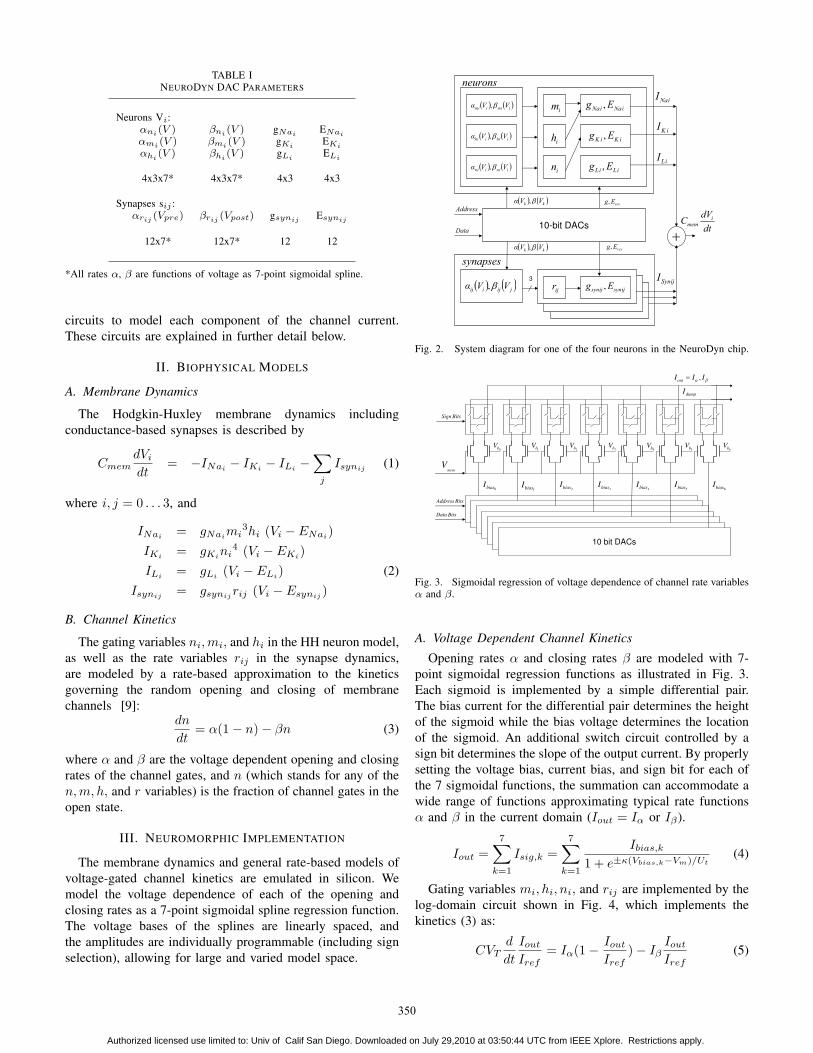
TABLE INEURODYN DAC PARAMETERS
Neurons Vi:αni (V ) βni (V ) gNai
ENai
αmi (V ) βmi (V ) gKiEKi
αhi(V ) βhi
(V ) gLiELi
4x3x7* 4x3x7* 4x3 4x3
Synapses sij :αrij (Vpre) βrij (Vpost) gsynij Esynij
12x7* 12x7* 12 12
*All rates α, β are functions of voltage as 7-point sigmoidal spline.
circuits to model each component of the channel current.These circuits are explained in further detail below.
II. BIOPHYSICAL MODELS
A. Membrane Dynamics
The Hodgkin-Huxley membrane dynamics includingconductance-based synapses is described by
CmemdVi
dt= −INai − IKi − ILi −
∑j
Isynij (1)
where i, j = 0 . . . 3, and
INai = gNaimi3hi (Vi − ENai)
IKi = gKini4 (Vi − EKi)
ILi = gLi (Vi − ELi) (2)Isynij = gsynij rij (Vi − Esynij )
B. Channel Kinetics
The gating variables ni,mi, and hi in the HH neuron model,as well as the rate variables rij in the synapse dynamics,are modeled by a rate-based approximation to the kineticsgoverning the random opening and closing of membranechannels [9]:
dn
dt= α(1− n)− βn (3)
where α and β are the voltage dependent opening and closingrates of the channel gates, and n (which stands for any of then, m, h, and r variables) is the fraction of channel gates in theopen state.
III. NEUROMORPHIC IMPLEMENTATION
The membrane dynamics and general rate-based models ofvoltage-gated channel kinetics are emulated in silicon. Wemodel the voltage dependence of each of the opening andclosing rates as a 7-point sigmoidal spline regression function.The voltage bases of the splines are linearly spaced, andthe amplitudes are individually programmable (including signselection), allowing for large and varied model space.
3
ijsynijsyn Eg ,
* + * +kk VVg d,
ijr
im
ih
in
iNaiNa Eg ,
iKiK Eg ,
iLiL Eg ,
* + * +jijiij VVg d,
-
neurons
synapses
iNaI
iKI
iLI
ijSynI
dt
dVC imem
Data
Address
10-bit DACs
revEg,
revEg,
* + * +iimiim VVg d,
* + * +kk VVg d,
* + * +iihiih VVg d,
* + * +iiniin VVg d,
Fig. 2. System diagram for one of the four neurons in the NeuroDyn chip.
0bV
memV
dumpI
1bV
2bV
3bV
4bV
5bV
6bV
0biasI
2biasI
3biasI
1biasI
4biasI
5biasI
6biasI
dc IIIout
,?
BitsData
BitsAddress
BitsSign
10 bit DACs
Fig. 3. Sigmoidal regression of voltage dependence of channel rate variablesα and β.
A. Voltage Dependent Channel Kinetics
Opening rates α and closing rates β are modeled with 7-point sigmoidal regression functions as illustrated in Fig. 3.Each sigmoid is implemented by a simple differential pair.The bias current for the differential pair determines the heightof the sigmoid while the bias voltage determines the locationof the sigmoid. An additional switch circuit controlled by asign bit determines the slope of the output current. By properlysetting the voltage bias, current bias, and sign bit for each ofthe 7 sigmoidal functions, the summation can accommodate awide range of functions approximating typical rate functionsα and β in the current domain (Iout = Iα or Iβ).
Iout =7∑
k=1
Isig,k =7∑
k=1
Ibias,k
1 + e±κ(Vbias,k−Vm)/Ut(4)
Gating variables mi, hi, ni, and rij are implemented by thelog-domain circuit shown in Fig. 4, which implements thekinetics (3) as:
CVTd
dt
Iout
Iref= Iα(1− Iout
Iref)− Iβ
Iout
Iref(5)
350
Authorized licensed use limited to: Univ of Calif San Diego. Downloaded on July 29,2010 at 03:50:44 UTC from IEEE Xplore. Restrictions apply.
Ic
Ic+Id+Iref
IrefInIc+Id
C
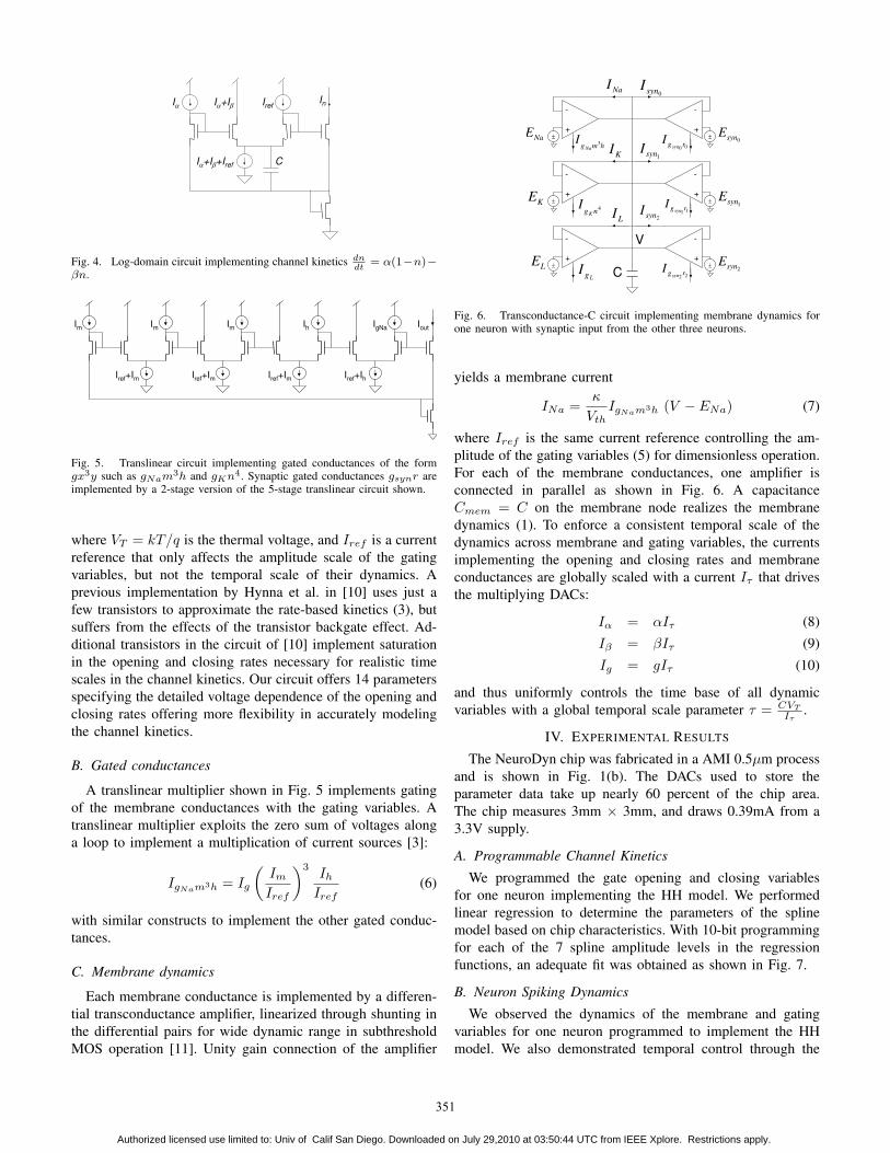
Fig. 4. Log-domain circuit implementing channel kinetics dndt
= α(1−n)−βn.
Im
Iref
+Im
Iout
IgNa
Ih
Iref
+Im
Iref
+Im
Iref
+Ih
Im
Im
Fig. 5. Translinear circuit implementing gated conductances of the formgx3y such as gNam3h and gKn4. Synaptic gated conductances gsynr areimplemented by a 2-stage version of the 5-stage translinear circuit shown.
where VT = kT/q is the thermal voltage, and Iref is a currentreference that only affects the amplitude scale of the gatingvariables, but not the temporal scale of their dynamics. Aprevious implementation by Hynna et al. in [10] uses just afew transistors to approximate the rate-based kinetics (3), butsuffers from the effects of the transistor backgate effect. Ad-ditional transistors in the circuit of [10] implement saturationin the opening and closing rates necessary for realistic timescales in the channel kinetics. Our circuit offers 14 parametersspecifying the detailed voltage dependence of the opening andclosing rates offering more flexibility in accurately modelingthe channel kinetics.
B. Gated conductances
A translinear multiplier shown in Fig. 5 implements gatingof the membrane conductances with the gating variables. Atranslinear multiplier exploits the zero sum of voltages alonga loop to implement a multiplication of current sources [3]:
IgNam3h = Ig
(Im
Iref
)3Ih
Iref(6)
with similar constructs to implement the other gated conduc-tances.
C. Membrane dynamics
Each membrane conductance is implemented by a differen-tial transconductance amplifier, linearized through shunting inthe differential pairs for wide dynamic range in subthresholdMOS operation [11]. Unity gain connection of the amplifier
+
V
C
‒
+‒
+‒ ‒
+
- -
‒+
‒+
00rgsyn
I
11rg syn
I
LgI
hmgNa
I 3
4ngK
I
22rg syn
I
NaI
KI
LI 2syn
I
1synI
0synI
LE
KE
NaE
2synE
1synE
0synE
-
- -
-
Fig. 6. Transconductance-C circuit implementing membrane dynamics forone neuron with synaptic input from the other three neurons.
yields a membrane current
INa =κ
VthIgNam3h (V − ENa) (7)
where Iref is the same current reference controlling the am-plitude of the gating variables (5) for dimensionless operation.For each of the membrane conductances, one amplifier isconnected in parallel as shown in Fig. 6. A capacitanceCmem = C on the membrane node realizes the membranedynamics (1). To enforce a consistent temporal scale of thedynamics across membrane and gating variables, the currentsimplementing the opening and closing rates and membraneconductances are globally scaled with a current Iτ that drivesthe multiplying DACs:
Iα = αIτ (8)Iβ = βIτ (9)Ig = gIτ (10)
and thus uniformly controls the time base of all dynamicvariables with a global temporal scale parameter τ = CVT
Iτ.
IV. EXPERIMENTAL RESULTS
The NeuroDyn chip was fabricated in a AMI 0.5µm processand is shown in Fig. 1(b). The DACs used to store theparameter data take up nearly 60 percent of the chip area.The chip measures 3mm × 3mm, and draws 0.39mA from a3.3V supply.
A. Programmable Channel Kinetics
We programmed the gate opening and closing variablesfor one neuron implementing the HH model. We performedlinear regression to determine the parameters of the splinemodel based on chip characteristics. With 10-bit programmingfor each of the 7 spline amplitude levels in the regressionfunctions, an adequate fit was obtained as shown in Fig. 7.
B. Neuron Spiking Dynamics
We observed the dynamics of the membrane and gatingvariables for one neuron programmed to implement the HHmodel. We also demonstrated temporal control through the
351
Authorized licensed use limited to: Univ of Calif San Diego. Downloaded on July 29,2010 at 03:50:44 UTC from IEEE Xplore. Restrictions apply.
-20 -10 0 10 20 30 40 50 60 70 800
5
10
Membrane Voltage (mV)
Measured cm
Target cm
Measured dm
Target dm
-20 -10 0 10 20 30 40 50 60 70 800
0.5
1
Membrane Voltage (mV)
Measured ch
Target ch
Measured dh
Target dh
-20 -10 0 10 20 30 40 50 60 70 800
0.5
1
Membrane Voltage (mV)
Measured cn
Target cn
Measured dn
Target dn
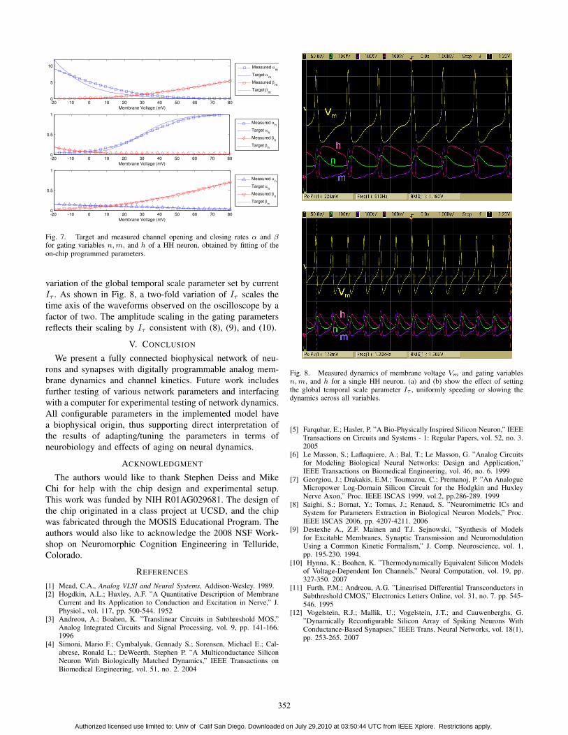
Fig. 7. Target and measured channel opening and closing rates α and βfor gating variables n, m, and h of a HH neuron, obtained by fitting of theon-chip programmed parameters.
variation of the global temporal scale parameter set by currentIτ . As shown in Fig. 8, a two-fold variation of Iτ scales thetime axis of the waveforms observed on the oscilloscope by afactor of two. The amplitude scaling in the gating parametersreflects their scaling by Iτ consistent with (8), (9), and (10).
V. CONCLUSION
We present a fully connected biophysical network of neu-rons and synapses with digitally programmable analog mem-brane dynamics and channel kinetics. Future work includesfurther testing of various network parameters and interfacingwith a computer for experimental testing of network dynamics.All configurable parameters in the implemented model havea biophysical origin, thus supporting direct interpretation ofthe results of adapting/tuning the parameters in terms ofneurobiology and effects of aging on neural dynamics.
ACKNOWLEDGMENT
The authors would like to thank Stephen Deiss and MikeChi for help with the chip design and experimental setup.This work was funded by NIH R01AG029681. The design ofthe chip originated in a class project at UCSD, and the chipwas fabricated through the MOSIS Educational Program. Theauthors would also like to acknowledge the 2008 NSF Work-shop on Neuromorphic Cognition Engineering in Telluride,Colorado.
REFERENCES
[1] Mead, C.A., Analog VLSI and Neural Systems, Addison-Wesley. 1989.[2] Hogdkin, A.L.; Huxley, A.F. ”A Quantitative Description of Membrane
Current and Its Application to Conduction and Excitation in Nerve,” J.Physiol., vol. 117, pp. 500-544. 1952
[3] Andreou, A.; Boahen, K. ”Translinear Circuits in Subthreshold MOS,”Analog Integrated Circuits and Signal Processing, vol. 9, pp. 141-166.1996
[4] Simoni, Mario F.; Cymbalyuk, Gennady S.; Sorensen, Michael E.; Cal-abrese, Ronald L.; DeWeerth, Stephen P. ”A Multiconductance SiliconNeuron With Biologically Matched Dynamics,” IEEE Transactions onBiomedical Engineering, vol. 51, no. 2. 2004
Fig. 8. Measured dynamics of membrane voltage Vm and gating variablesn, m, and h for a single HH neuron. (a) and (b) show the effect of settingthe global temporal scale parameter Iτ , uniformly speeding or slowing thedynamics across all variables.
[5] Farquhar, E.; Hasler, P. ”A Bio-Physically Inspired Silicon Neuron,” IEEETransactions on Circuits and Systems - 1: Regular Papers, vol. 52, no. 3.2005
[6] Le Masson, S.; Laflaquiere, A.; Bal, T.; Le Masson, G. ”Analog Circuitsfor Modeling Biological Neural Networks: Design and Application,”IEEE Transactions on Biomedical Engineering, vol. 46, no. 6. 1999
[7] Georgiou, J.; Drakakis, E.M.; Toumazou, C.; Premanoj, P. ”An AnalogueMicropower Log-Domain Silicon Circuit for the Hodgkin and HuxleyNerve Axon,” Proc. IEEE ISCAS 1999, vol.2, pp.286-289. 1999
[8] Saighi, S.; Bornat, Y.; Tomas, J.; Renaud, S. ”Neuromimetric ICs andSystem for Parameters Extraction in Biological Neuron Models,” Proc.IEEE ISCAS 2006, pp. 4207-4211. 2006
[9] Destexhe A., Z.F. Mainen and T.J. Sejnowski, ”Synthesis of Modelsfor Excitable Membranes, Synaptic Transmission and NeuromodulationUsing a Common Kinetic Formalism,” J. Comp. Neuroscience, vol. 1,pp. 195-230. 1994.
[10] Hynna, K.; Boahen, K. ”Thermodynamically Equivalent Silicon Modelsof Voltage-Dependent Ion Channels,” Neural Computation, vol. 19, pp.327-350. 2007
[11] Furth, P.M.; Andreou, A.G. ”Linearised Differential Transconductors inSubthreshold CMOS,” Electronics Letters Online, vol. 31, no. 7. pp. 545-546. 1995
[12] Vogelstein, R.J.; Mallik, U.; Vogelstein, J.T.; and Cauwenberghs, G.”Dynamically Reconfigurable Silicon Array of Spiking Neurons WithConductance-Based Synapses,” IEEE Trans. Neural Networks, vol. 18(1),pp. 253-265. 2007
352
Authorized licensed use limited to: Univ of Calif San Diego. Downloaded on July 29,2010 at 03:50:44 UTC from IEEE Xplore. Restrictions apply.