a novel dendrite‐free mn 2+ /zn 2+ hybrid battery with 2.3...
TRANSCRIPT
www.advenergymat.de
Full paper
1901469 (1 of 10) © 2019 WILEY-VCH Verlag GmbH & Co. KGaA, Weinheim
A Novel Dendrite-Free Mn2+/Zn2+ Hybrid Battery with 2.3 V Voltage Window and 11000-Cycle Lifespan
Ming Li, Qiu He, Zilan Li, Qi Li,* Yuxin Zhang, Jiashen Meng, Xiong Liu, Shidong Li, Buke Wu, Lineng Chen, Ziang Liu, Wen Luo, Chunhua Han,* and Liqiang Mai*
DOI: 10.1002/aenm.201901469
further development.[2] Hence, exploring novel approaches to achieve more effi-cient energy storage is highly demanded. Recently, aqueous batteries are attracting unprecedented attention particularly owing to their high safety, high ion con-ductivity, low cost, and environmental friendliness.[3] To date, numerous aqueous batteries based on Li+, Na+, K+, Mg2+, Ca2+, Zn2+, Al3+, Fe3+, and/or mixed metal ions as charge carriers have been reported,[4] which find potential applications in fields such as grid-scale energy storage, wear-able devices, and etc.[5]
Among them, as a promising candi-date, the rechargeable aqueous Zn-based batteries (AZBs) including Zn-ion bat-teries (mild electrolyte),[6] Zn–Co/Ag/Ni alkaline batteries[7] and Zn–air bat-teries in alkaline electrolyte[8] have been extensively studied due to their unparal-leled advantages of Zn anode. In gen-eral, metal Zn has the features of high theoretical capacity (820 mAh g−1), high electrical conductivity, nontoxicity, easy
processing, and suitable redox potential (−0.76 V vs standard hydrogen electrode).[9] However, most of AZBs reported so far have encountered the same challenges, which are the narrow voltage window, unsatisfactory capacity, and poor cycling per-formance.[10] For example, all Zn-ion batteries operated in mild electrolyte including Zn//V-based, Zn//Mn-based, and Zn//Prussian blue analogs-based hold a narrow voltage window of 0.3–1.6, 0.9–1.8, and 0.2–1.8 V, respectively.[11] Even though AZBs in alkaline electrolyte display a higher voltage than that achieved in mild medium, their voltage windows are still only about 1.2–1.9 V.[12] Meanwhile, the alkaline electrolytes show stronger corrosion than mild neutral electrolytes, which greatly limit their wide applications. Moreover, the unstable cycling performance in AZBs due to the Zn dendrites and side reaction on the surface of Zn anode is also unsatisfactory.[10] To date, the electrolyte optimization or structural design are the common ways to suppress the growth of Zn dendrite and improve the cycling stability. For example, Chen and co-workers reported that aqueous electrolyte Zn(CF3SO3)2 can suppress the for-mation of detrimental dendrites in AZBs owing to the better reversibility and faster kinetics of Zn deposition/dissolution than that in ZnSO4 electrolyte.[13] However, Zn(CF3SO3)2 is too expensive (≈$ 8.1 g−1, prices from Sigma-Aldrich) to be applied
With the increasing energy crisis and environmental pollution, recharge-able aqueous Zn-based batteries (AZBs) are receiving unprecedented atten-tion due to their list of merits, such as low cost, high safety, and nontoxicity. However, the limited voltage window, Zn dendrites, and relatively low specific capacity are still great challenges. In this work, a new reaction mechanism of reversible Mn2+ ion oxidation deposition is introduced to AZBs. The assem-bled Mn2+/Zn2+ hybrid battery (Mn2+/Zn2+ HB) based on a hybrid storage mechanism including Mn2+ ion deposition, Zn2+ ion insertion, and conver-sion reaction of MnO2 can achieve an ultrawide voltage window (0–2.3 V) and high capacity (0.96 mAh cm−2). Furthermore, the carbon nanotubes coated Zn anode is proved to effectively inhibit Zn dendrites and control side reac-tion, hence exhibiting an ultrastable cycling (33 times longer than bare Zn foil) without obvious polarization. Benefiting from the optimal Zn anode and highly reversible Mn2+/Zn2+ hybrid storage mechanism, the Mn2+/Zn2+ HB shows an excellent cycling performance over 11 000 cycles with a 100% capacity reten-tion. To the best of the authors’ knowledge, it is the highest reported cycling performance and wide voltage window for AZBs with mild electrolyte, which may inspire a great insight into designing high-performance aqueous batteries.
M. Li, Q. He, Z. L. Li, Prof. Q. Li, Y. X. Zhang, J. S. Meng, X. Liu, S. D. Li, B. K. Wu, L. N. Chen, Z. A. Liu, Dr. W. Luo, Prof. C. H. Han, Prof. L. Q. MaiState Key Laboratory of Advanced Technology for Materials Synthesis and ProcessingWuhan University of TechnologyHubei, Wuhan 430070, P. R. ChinaE-mail: [email protected]; [email protected]; [email protected]
The ORCID identification number(s) for the author(s) of this article can be found under https://doi.org/10.1002/aenm.201901469.
Hybrid Batteries
1. Introduction
With the consumption of fossil fuels and the ever-growing demands for renewable clean energy, it is highly desired to develop high-performance energy storage/conversion systems with high capacity, long lifespan, low cost, and envi-ronmental friendliness.[1] Nowadays, the commercial lithium ion batteries have been widely applied in many fields due to their high energy densities. However, a series of intrinsic drawbacks including poor safety, environmental pollution derived from organic electrolytes as well as high cost from the scarce lithium resources remain challenges and hinder their
Adv. Energy Mater. 2019, 1901469
www.advenergymat.dewww.advancedsciencenews.com
© 2019 WILEY-VCH Verlag GmbH & Co. KGaA, Weinheim1901469 (2 of 10)
in real energy storage systems.[14] Researchers have also pro-posed to suppress the growth of dendrites by constructing Zn anodes with a 3D structure.[15] However, its complex production processes and high production costs limit their wide applica-tions. Therefore, exploring a simple, low-cost and effective way to assemble high-performance AZBs with a wide voltage and stable Zn anode is still a great challenge.
Herein, inspired by the new Mn–H battery reported by Cui and co-workers,[16] we propose and demonstrate a low-cost Mn2+/Zn2+ hybrid battery (Mn2+/Zn2+ HB) based on a new-type hybrid storage mechanism including Mn2+/MnO2 reversible deposition/dissolution, Zn2+ insertion, and chemical conversion reaction (between MnO2 and MnOOH). In particular, by intro-ducing a novel mechanism based on deposition/ dissolution reactions between soluble Mn2+ and solid MnO2 in electrolyte, a wide voltage window of 2.3 V and excellent specific capacity of 0.96 mAh cm−2 can be achieved. Moreover, it is worth noting that the MnO2 cathode is synthesized by simply soaking the low-cost polyester cloth into carbon nanotubes (CNTs) ink fol-lowed by an in situ self-sacrificing reaction. While a simple method is applied to obtain the antidendrite CNT-coated Zn anode, leading to significantly improved stability of Zn foil for over 400 h cycling without obvious polarization. Benefiting from the highly reversible deposition/ dissolution mechanism in the MnO2 cathode and the stable Zn anode, the Mn2+/Zn2+ hybrid battery exhibits ultrastable cycle performance of over 11 000 cycles without decay as well as almost 100% Coulombic efficiency. This work provides a new way to improve battery capacity and cycling performance through electrolyte regula-tion and dendritic inhibition. It heralds a new opportunity in the development of high performance, low-cost, safe aqueous batteries.
2. Results and Discussion
2.1. Morphology and Structure Characterization
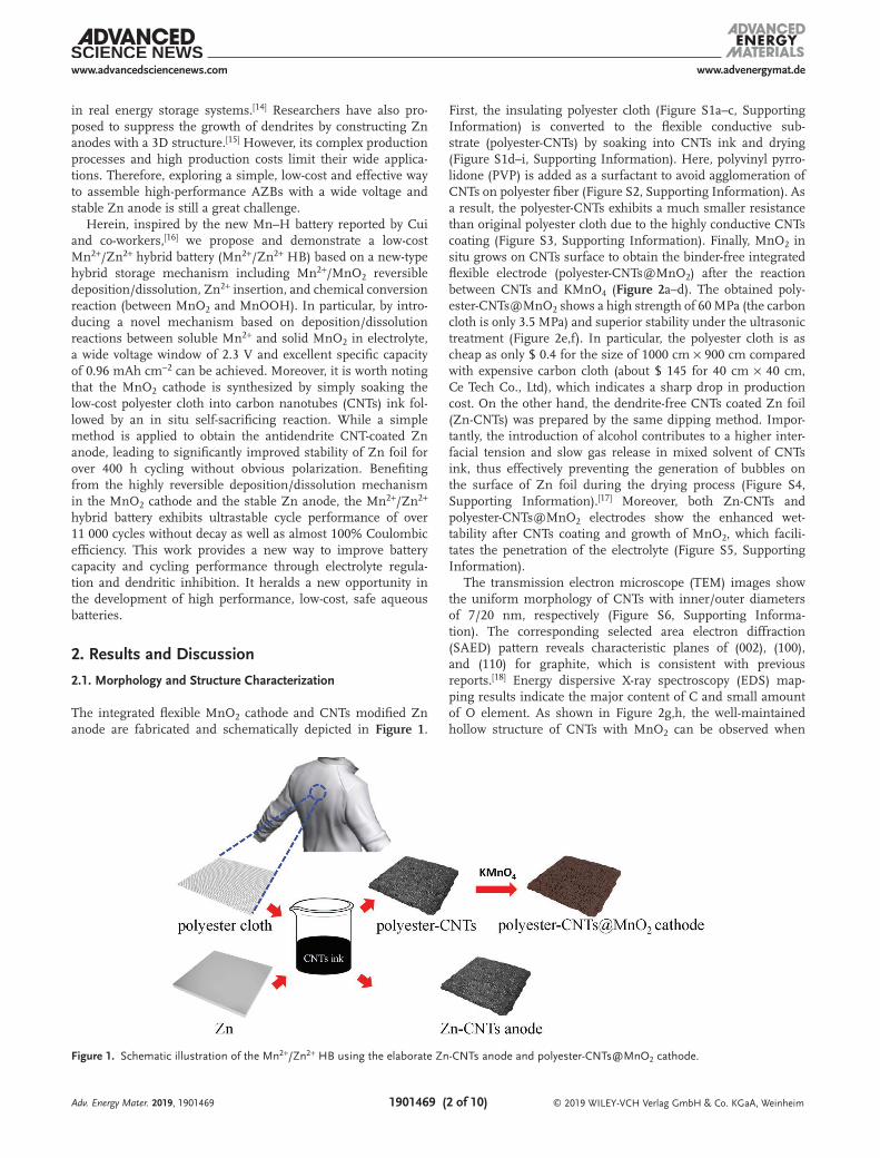
The integrated flexible MnO2 cathode and CNTs modified Zn anode are fabricated and schematically depicted in Figure 1.
First, the insulating polyester cloth (Figure S1a–c, Supporting Information) is converted to the flexible conductive sub-strate (polyester-CNTs) by soaking into CNTs ink and drying (Figure S1d–i, Supporting Information). Here, polyvinyl pyrro-lidone (PVP) is added as a surfactant to avoid agglomeration of CNTs on polyester fiber (Figure S2, Supporting Information). As a result, the polyester-CNTs exhibits a much smaller resistance than original polyester cloth due to the highly conductive CNTs coating (Figure S3, Supporting Information). Finally, MnO2 in situ grows on CNTs surface to obtain the binder-free integrated flexible electrode (polyester-CNTs@MnO2) after the reaction between CNTs and KMnO4 (Figure 2a–d). The obtained poly-ester-CNTs@MnO2 shows a high strength of 60 MPa (the carbon cloth is only 3.5 MPa) and superior stability under the ultrasonic treatment (Figure 2e,f). In particular, the polyester cloth is as cheap as only $ 0.4 for the size of 1000 cm × 900 cm compared with expensive carbon cloth (about $ 145 for 40 cm × 40 cm, Ce Tech Co., Ltd), which indicates a sharp drop in production cost. On the other hand, the dendrite-free CNTs coated Zn foil (Zn-CNTs) was prepared by the same dipping method. Impor-tantly, the introduction of alcohol contributes to a higher inter-facial tension and slow gas release in mixed solvent of CNTs ink, thus effectively preventing the generation of bubbles on the surface of Zn foil during the drying process (Figure S4, Supporting Information).[17] Moreover, both Zn-CNTs and polyester-CNTs@MnO2 electrodes show the enhanced wet-tability after CNTs coating and growth of MnO2, which facili-tates the penetration of the electrolyte (Figure S5, Supporting Information).
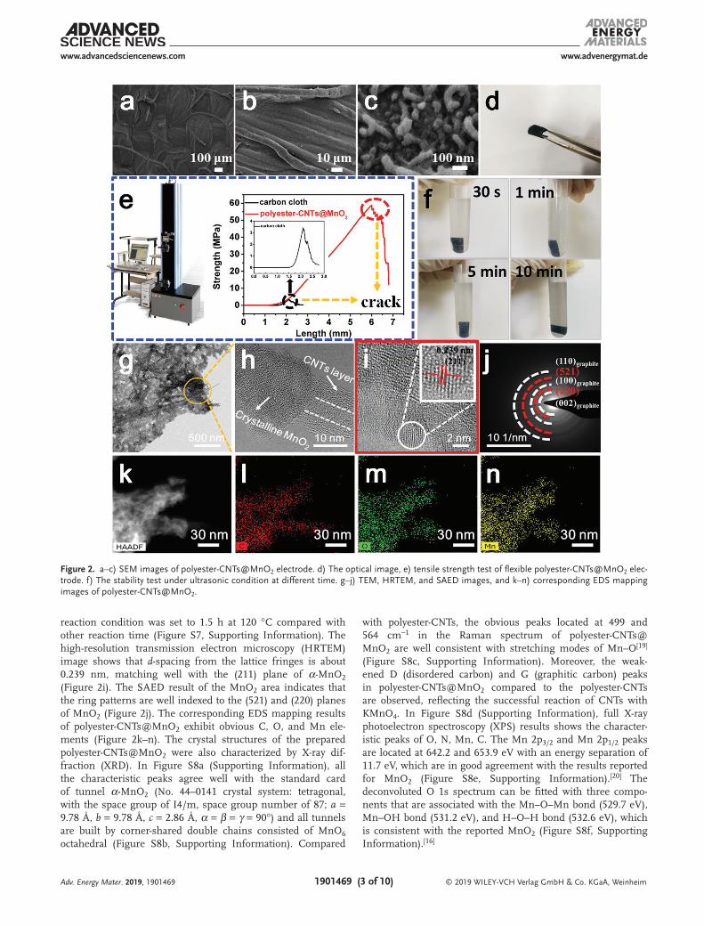
The transmission electron microscope (TEM) images show the uniform morphology of CNTs with inner/outer diameters of 7/20 nm, respectively (Figure S6, Supporting Informa-tion). The corresponding selected area electron diffraction (SAED) pattern reveals characteristic planes of (002), (100), and (110) for graphite, which is consistent with previous reports.[18] Energy dispersive X-ray spectroscopy (EDS) map-ping results indicate the major content of C and small amount of O element. As shown in Figure 2g,h, the well-maintained hollow structure of CNTs with MnO2 can be observed when
Adv. Energy Mater. 2019, 1901469
Figure 1. Schematic illustration of the Mn2+/Zn2+ HB using the elaborate Zn-CNTs anode and polyester-CNTs@MnO2 cathode.
www.advenergymat.dewww.advancedsciencenews.com
© 2019 WILEY-VCH Verlag GmbH & Co. KGaA, Weinheim1901469 (3 of 10)
reaction condition was set to 1.5 h at 120 °C compared with other reaction time (Figure S7, Supporting Information). The high-resolution transmission electron microscopy (HRTEM) image shows that d-spacing from the lattice fringes is about 0.239 nm, matching well with the (211) plane of α-MnO2 (Figure 2i). The SAED result of the MnO2 area indicates that the ring patterns are well indexed to the (521) and (220) planes of MnO2 (Figure 2j). The corresponding EDS mapping results of polyester-CNTs@MnO2 exhibit obvious C, O, and Mn ele-ments (Figure 2k–n). The crystal structures of the prepared polyester-CNTs@MnO2 were also characterized by X-ray dif-fraction (XRD). In Figure S8a (Supporting Information), all the characteristic peaks agree well with the standard card of tunnel α-MnO2 (No. 44–0141 crystal system: tetragonal, with the space group of I4/m, space group number of 87; a = 9.78 Å, b = 9.78 Å, c = 2.86 Å, α = β = γ = 90°) and all tunnels are built by corner-shared double chains consisted of MnO6 octahedral (Figure S8b, Supporting Information). Compared
with polyester-CNTs, the obvious peaks located at 499 and 564 cm−1 in the Raman spectrum of polyester-CNTs@MnO2 are well consistent with stretching modes of Mn–O[19] (Figure S8c, Supporting Information). Moreover, the weak-ened D (disordered carbon) and G (graphitic carbon) peaks in polyester-CNTs@MnO2 compared to the polyester-CNTs are observed, reflecting the successful reaction of CNTs with KMnO4. In Figure S8d (Supporting Information), full X-ray photoelectron spectroscopy (XPS) results shows the character-istic peaks of O, N, Mn, C. The Mn 2p3/2 and Mn 2p1/2 peaks are located at 642.2 and 653.9 eV with an energy separation of 11.7 eV, which are in good agreement with the results reported for MnO2 (Figure S8e, Supporting Information).[20] The deconvoluted O 1s spectrum can be fitted with three compo-nents that are associated with the Mn–O–Mn bond (529.7 eV), Mn–OH bond (531.2 eV), and H–O–H bond (532.6 eV), which is consistent with the reported MnO2 (Figure S8f, Supporting Information).[16]
Adv. Energy Mater. 2019, 1901469
Figure 2. a–c) SEM images of polyester-CNTs@MnO2 electrode. d) The optical image, e) tensile strength test of flexible polyester-CNTs@MnO2 elec-trode. f) The stability test under ultrasonic condition at different time. g–j) TEM, HRTEM, and SAED images, and k–n) corresponding EDS mapping images of polyester-CNTs@MnO2.
www.advenergymat.dewww.advancedsciencenews.com
© 2019 WILEY-VCH Verlag GmbH & Co. KGaA, Weinheim1901469 (4 of 10)
2.2. Antidendrite Properties of Zn-CNTs Anode
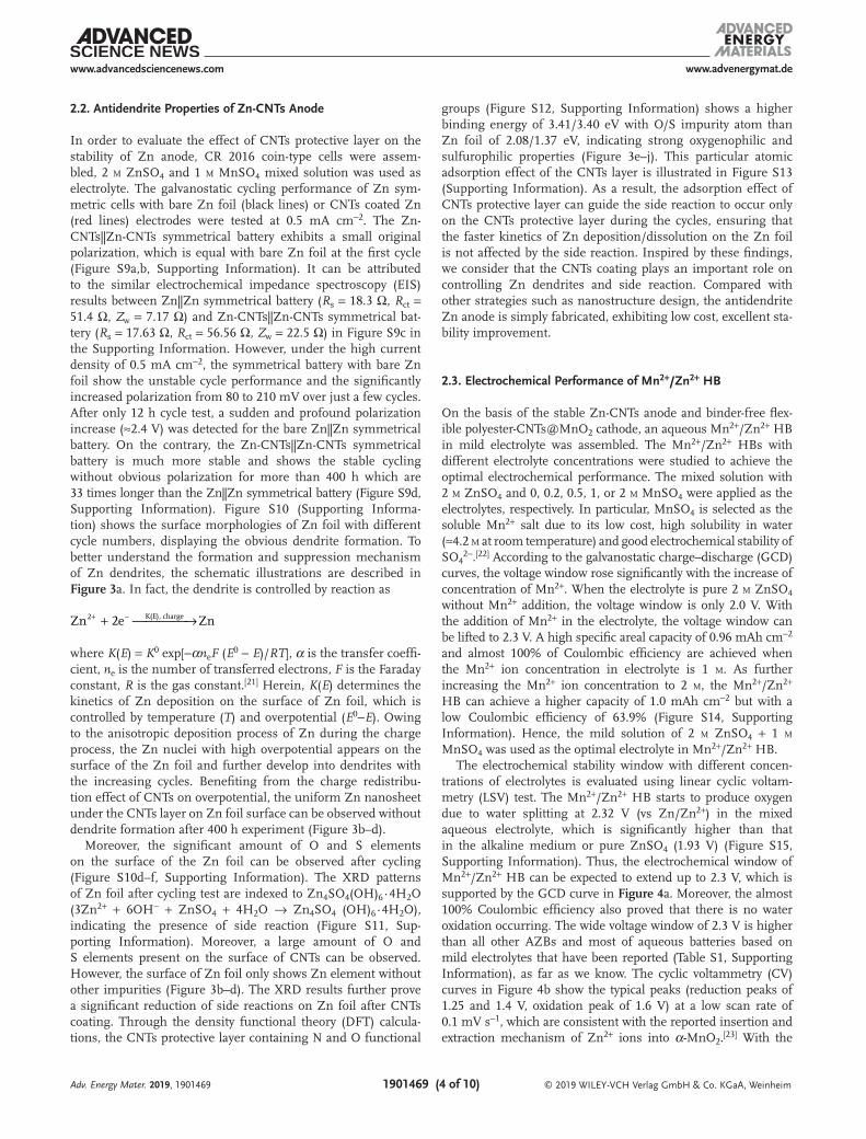
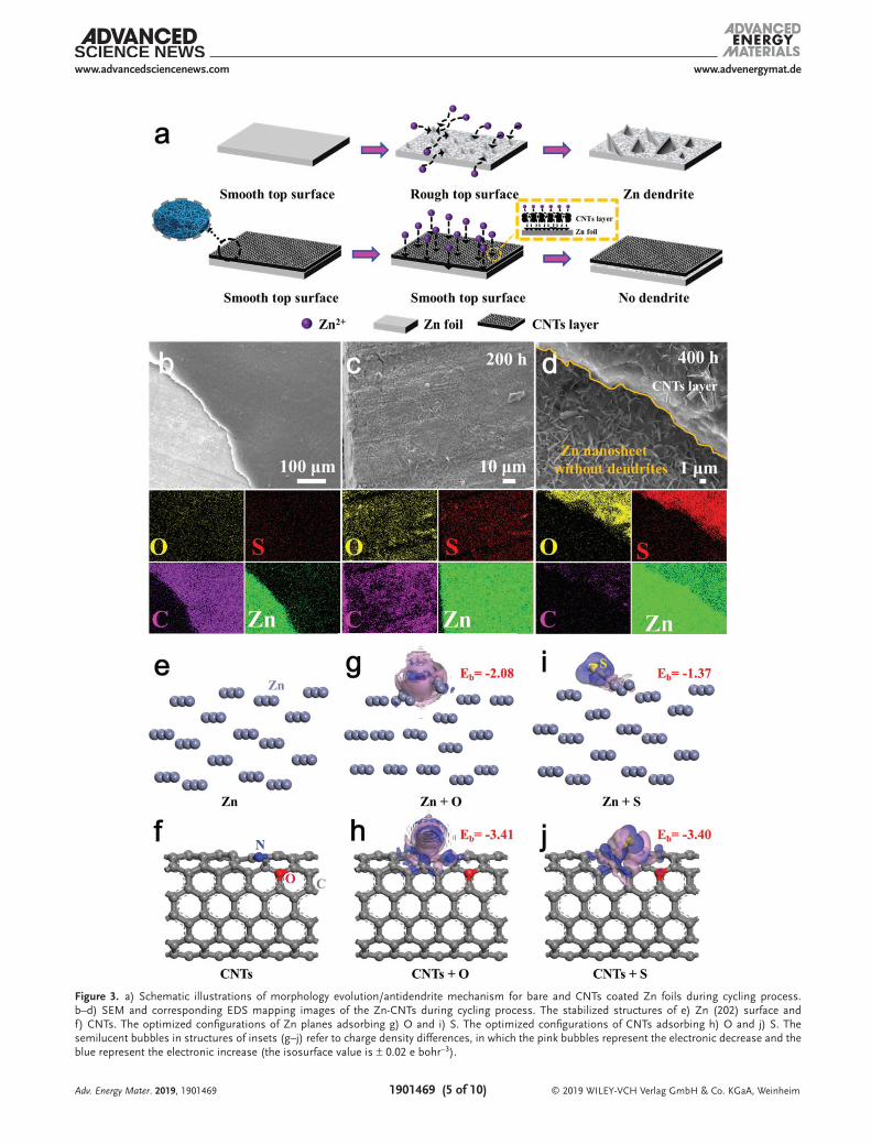
In order to evaluate the effect of CNTs protective layer on the stability of Zn anode, CR 2016 coin-type cells were assem-bled, 2 m ZnSO4 and 1 m MnSO4 mixed solution was used as electrolyte. The galvanostatic cycling performance of Zn sym-metric cells with bare Zn foil (black lines) or CNTs coated Zn (red lines) electrodes were tested at 0.5 mA cm−2. The Zn-CNTs||Zn-CNTs symmetrical battery exhibits a small original polarization, which is equal with bare Zn foil at the first cycle (Figure S9a,b, Supporting Information). It can be attributed to the similar electrochemical impedance spectroscopy (EIS) results between Zn||Zn symmetrical battery (Rs = 18.3 Ω, Rct = 51.4 Ω, Zw = 7.17 Ω) and Zn-CNTs||Zn-CNTs symmetrical bat-tery (Rs = 17.63 Ω, Rct = 56.56 Ω, Zw = 22.5 Ω) in Figure S9c in the Supporting Information. However, under the high current density of 0.5 mA cm−2, the symmetrical battery with bare Zn foil show the unstable cycle performance and the significantly increased polarization from 80 to 210 mV over just a few cycles. After only 12 h cycle test, a sudden and profound polarization increase (≈2.4 V) was detected for the bare Zn||Zn symmetrical battery. On the contrary, the Zn-CNTs||Zn-CNTs symmetrical battery is much more stable and shows the stable cycling without obvious polarization for more than 400 h which are 33 times longer than the Zn||Zn symmetrical battery (Figure S9d, Supporting Information). Figure S10 (Supporting Informa-tion) shows the surface morphologies of Zn foil with different cycle numbers, displaying the obvious dendrite formation. To better understand the formation and suppression mechanism of Zn dendrites, the schematic illustrations are described in Figure 3a. In fact, the dendrite is controlled by reaction as
Zn 2e Zn2 K(E), charge+ →+ −
where K(E) = K0 exp[−αneF (E0 − E)/RT], α is the transfer coeffi-cient, ne is the number of transferred electrons, F is the Faraday constant, R is the gas constant.[21] Herein, K(E) determines the kinetics of Zn deposition on the surface of Zn foil, which is controlled by temperature (T) and overpotential (E0−E). Owing to the anisotropic deposition process of Zn during the charge process, the Zn nuclei with high overpotential appears on the surface of the Zn foil and further develop into dendrites with the increasing cycles. Benefiting from the charge redistribu-tion effect of CNTs on overpotential, the uniform Zn nanosheet under the CNTs layer on Zn foil surface can be observed without dendrite formation after 400 h experiment (Figure 3b–d).
Moreover, the significant amount of O and S elements on the surface of the Zn foil can be observed after cycling (Figure S10d–f, Supporting Information). The XRD patterns of Zn foil after cycling test are indexed to Zn4SO4(OH)6∙4H2O (3Zn2+ + 6OH− + ZnSO4 + 4H2O → Zn4SO4 (OH)6∙4H2O), indicating the presence of side reaction (Figure S11, Sup-porting Information). Moreover, a large amount of O and S elements present on the surface of CNTs can be observed. However, the surface of Zn foil only shows Zn element without other impurities (Figure 3b–d). The XRD results further prove a significant reduction of side reactions on Zn foil after CNTs coating. Through the density functional theory (DFT) calcula-tions, the CNTs protective layer containing N and O functional
groups (Figure S12, Supporting Information) shows a higher binding energy of 3.41/3.40 eV with O/S impurity atom than Zn foil of 2.08/1.37 eV, indicating strong oxygenophilic and sulfurophilic properties (Figure 3e–j). This particular atomic adsorption effect of the CNTs layer is illustrated in Figure S13 (Supporting Information). As a result, the adsorption effect of CNTs protective layer can guide the side reaction to occur only on the CNTs protective layer during the cycles, ensuring that the faster kinetics of Zn deposition/dissolution on the Zn foil is not affected by the side reaction. Inspired by these findings, we consider that the CNTs coating plays an important role on controlling Zn dendrites and side reaction. Compared with other strategies such as nanostructure design, the antidendrite Zn anode is simply fabricated, exhibiting low cost, excellent sta-bility improvement.
2.3. Electrochemical Performance of Mn2+/Zn2+ HB
On the basis of the stable Zn-CNTs anode and binder-free flex-ible polyester-CNTs@MnO2 cathode, an aqueous Mn2+/Zn2+ HB in mild electrolyte was assembled. The Mn2+/Zn2+ HBs with different electrolyte concentrations were studied to achieve the optimal electrochemical performance. The mixed solution with 2 m ZnSO4 and 0, 0.2, 0.5, 1, or 2 m MnSO4 were applied as the electrolytes, respectively. In particular, MnSO4 is selected as the soluble Mn2+ salt due to its low cost, high solubility in water (≈4.2 m at room temperature) and good electrochemical stability of SO4
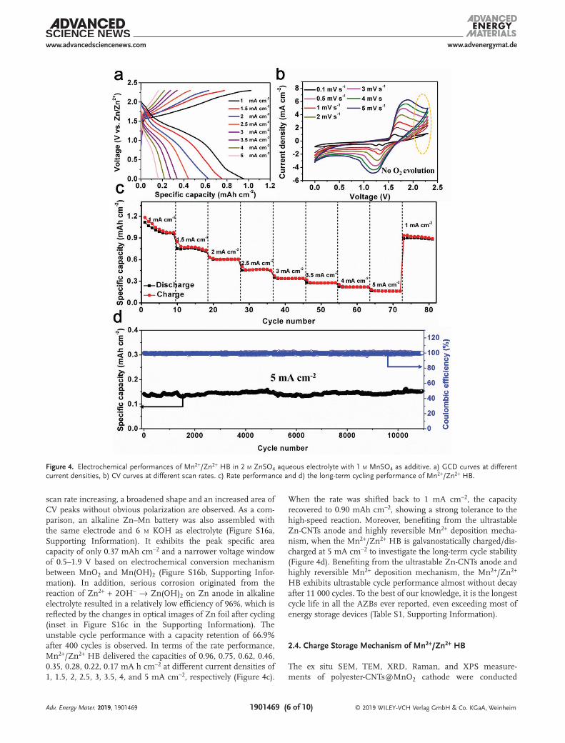
2−.[22] According to the galvanostatic charge–discharge (GCD) curves, the voltage window rose significantly with the increase of concentration of Mn2+. When the electrolyte is pure 2 m ZnSO4 without Mn2+ addition, the voltage window is only 2.0 V. With the addition of Mn2+ in the electrolyte, the voltage window can be lifted to 2.3 V. A high specific areal capacity of 0.96 mAh cm−2 and almost 100% of Coulombic efficiency are achieved when the Mn2+ ion concentration in electrolyte is 1 m. As further increasing the Mn2+ ion concentration to 2 m, the Mn2+/Zn2+ HB can achieve a higher capacity of 1.0 mAh cm−2 but with a low Coulombic efficiency of 63.9% (Figure S14, Supporting Information). Hence, the mild solution of 2 m ZnSO4 + 1 m MnSO4 was used as the optimal electrolyte in Mn2+/Zn2+ HB.
The electrochemical stability window with different concen-trations of electrolytes is evaluated using linear cyclic voltam-metry (LSV) test. The Mn2+/Zn2+ HB starts to produce oxygen due to water splitting at 2.32 V (vs Zn/Zn2+) in the mixed aqueous electrolyte, which is significantly higher than that in the alkaline medium or pure ZnSO4 (1.93 V) (Figure S15, Supporting Information). Thus, the electrochemical window of Mn2+/Zn2+ HB can be expected to extend up to 2.3 V, which is supported by the GCD curve in Figure 4a. Moreover, the almost 100% Coulombic efficiency also proved that there is no water oxidation occurring. The wide voltage window of 2.3 V is higher than all other AZBs and most of aqueous batteries based on mild electrolytes that have been reported (Table S1, Supporting Information), as far as we know. The cyclic voltammetry (CV) curves in Figure 4b show the typical peaks (reduction peaks of 1.25 and 1.4 V, oxidation peak of 1.6 V) at a low scan rate of 0.1 mV s−1, which are consistent with the reported insertion and extraction mechanism of Zn2+ ions into α-MnO2.[23] With the
Adv. Energy Mater. 2019, 1901469
www.advenergymat.dewww.advancedsciencenews.com
© 2019 WILEY-VCH Verlag GmbH & Co. KGaA, Weinheim1901469 (5 of 10)Adv. Energy Mater. 2019, 1901469
Figure 3. a) Schematic illustrations of morphology evolution/antidendrite mechanism for bare and CNTs coated Zn foils during cycling process. b–d) SEM and corresponding EDS mapping images of the Zn-CNTs during cycling process. The stabilized structures of e) Zn (202) surface and f) CNTs. The optimized configurations of Zn planes adsorbing g) O and i) S. The optimized configurations of CNTs adsorbing h) O and j) S. The semilucent bubbles in structures of insets (g–j) refer to charge density differences, in which the pink bubbles represent the electronic decrease and the blue represent the electronic increase (the isosurface value is ± 0.02 e bohr−3).
www.advenergymat.dewww.advancedsciencenews.com
© 2019 WILEY-VCH Verlag GmbH & Co. KGaA, Weinheim1901469 (6 of 10)
scan rate increasing, a broadened shape and an increased area of CV peaks without obvious polarization are observed. As a com-parison, an alkaline Zn–Mn battery was also assembled with the same electrode and 6 m KOH as electrolyte (Figure S16a, Supporting Information). It exhibits the peak specific area capacity of only 0.37 mAh cm−2 and a narrower voltage window of 0.5–1.9 V based on electrochemical conversion mechanism between MnO2 and Mn(OH)2 (Figure S16b, Supporting Infor-mation). In addition, serious corrosion originated from the reaction of Zn2+ + 2OH− → Zn(OH)2 on Zn anode in alkaline electrolyte resulted in a relatively low efficiency of 96%, which is reflected by the changes in optical images of Zn foil after cycling (inset in Figure S16c in the Supporting Information). The unstable cycle performance with a capacity retention of 66.9% after 400 cycles is observed. In terms of the rate performance, Mn2+/Zn2+ HB delivered the capacities of 0.96, 0.75, 0.62, 0.46, 0.35, 0.28, 0.22, 0.17 mA h cm−2 at different current densities of 1, 1.5, 2, 2.5, 3, 3.5, 4, and 5 mA cm−2, respectively (Figure 4c).
When the rate was shifted back to 1 mA cm−2, the capacity recovered to 0.90 mAh cm−2, showing a strong tolerance to the high-speed reaction. Moreover, benefiting from the ultrastable Zn-CNTs anode and highly reversible Mn2+ deposition mecha-nism, when the Mn2+/Zn2+ HB is galvanostatically charged/dis-charged at 5 mA cm−2 to investigate the long-term cycle stability (Figure 4d). Benefiting from the ultrastable Zn-CNTs anode and highly reversible Mn2+ deposition mechanism, the Mn2+/Zn2+ HB exhibits ultrastable cycle performance almost without decay after 11 000 cycles. To the best of our knowledge, it is the longest cycle life in all the AZBs ever reported, even exceeding most of energy storage devices (Table S1, Supporting Information).
2.4. Charge Storage Mechanism of Mn2+/Zn2+ HB
The ex situ SEM, TEM, XRD, Raman, and XPS measure-ments of polyester-CNTs@MnO2 cathode were conducted
Adv. Energy Mater. 2019, 1901469
Figure 4. Electrochemical performances of Mn2+/Zn2+ HB in 2 m ZnSO4 aqueous electrolyte with 1 m MnSO4 as additive. a) GCD curves at different current densities, b) CV curves at different scan rates. c) Rate performance and d) the long-term cycling performance of Mn2+/Zn2+ HB.
www.advenergymat.dewww.advancedsciencenews.com
© 2019 WILEY-VCH Verlag GmbH & Co. KGaA, Weinheim1901469 (7 of 10)
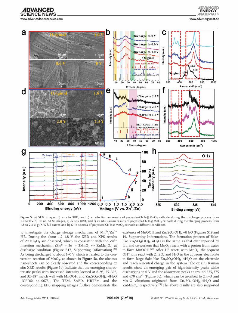
to investigate the charge storage mechanism of Mn2+/Zn2+ HB. During the about 1.2–1.8 V, the XRD and XPS results of ZnMn2O4 are observed, which is consistent with the Zn2+ insertion mechanism (Zn2+ + 2e− + 2MnO2 ↔ ZnMn2O4) at discharge condition (Figure S17, Supporting Information).[24] As being discharged to about 1–0 V which is related to the con-version reaction of MnO2, as shown in Figure 5a, the obvious nanosheets can be clearly observed and the corresponding ex situ XRD results (Figure 5b) indicate that the emerging charac-teristic peaks with increased intensity located at 8–9°, 25–30°, and 32–38° match well with MnOOH and Zn4SO4(OH)6∙4H2O (JCPDS: 44–0673). The TEM, SAED, HRTEM, and the corresponding EDS mapping images further demonstrate the
existence of MnOOH and Zn4SO4(OH)6∙4H2O (Figures S18 and 19, Supporting Information). The formation process of flake-like Zn4SO4(OH)6∙4H2O is the same as that ever reported by Liu and co-workers that MnO2 reacts with a proton from water to form MnOOH.[20] After H+ reacts with MnO2, the sequent OH− ions react with ZnSO4 and H2O in the aqueous electrolyte to form large flake-like Zn4SO4(OH)6∙4H2O on the electrode and reach a neutral charge in the system. The ex situ Raman results show an emerging pair of high-intensity peaks while discharging to 0 V and the absorption peaks at around 325/375 and 670 cm−1 (Figure 5c), which can be ascribed to Zn–O and Mn–O vibrations originated from Zn4SO4(OH)6∙4H2O and ZnMn2O4, respectively.[25] The above results are also supported
Adv. Energy Mater. 2019, 1901469
Figure 5. a) SEM images, b) ex situ XRD, and c) ex situ Raman results of polyester-CNTs@MnO2 cathode during the discharge process from 1.0 to 0 V. d) Ex situ SEM images, e) ex situ XRD, and f) ex situ Raman results of polyester-CNTs@MnO2 cathode during the charging process from 1.8 to 2.3 V. g) XPS full curves and h) O 1s spectra of polyester-CNTs@MnO2 cathode at different conditions.
www.advenergymat.dewww.advancedsciencenews.com
© 2019 WILEY-VCH Verlag GmbH & Co. KGaA, Weinheim1901469 (8 of 10)Adv. Energy Mater. 2019, 1901469
by the emerging strong Zn Auger and Zn 3s characteristic peaks due to Zn4SO4(OH)6∙4H2O,[26] and the increased Mn3+ species (MnOOH) are well supported (Figure S20, Supporting Information).[27] Hence, the reaction process can be described as below
Cathode: MnO H e MnOOH2 + + ↔+ −
12
Zn OH16
ZnSO46
H O16
Zn SO OH 4H O24 2 4 4 6 2( )+ + + ↔ ⋅+ −
Anode:1
2Zn
1
2Zn e2↔ ++ −
During the charge process from about 1.8 to 2.3 V, the ex situ SEM images show the obvious deposition product on the surface of cathode (Figure 5d; Figure S21, Supporting Information), indicating that a new mechanism of Mn2+ depo-sition occurs in this Mn2+/Zn2+ HB system. TEM and the cor-responding ex situ XRD (Figure 5e; Figure S22, Supporting Information) demonstrates that two types of MnO2 with dif-ferent crystal structures are deposited. The chain-structure MnO2 (Crystal system: Orthorhombic, with the space group of Pnma, space group number of 62; a = 9.26 Å, b = 2.86 Å, c = 4.51 Å, α = β = γ = 90°) is different from tunnel α-MnO2 (Figure S23, Supporting Information). Herein, the deposition mechanism can be described as below
Cathode: Mn 2H O MnO 4H 2e22 2+ ↔ + ++ + −
Anode: Zn 2e Zn2 + ↔+ −
Total reaction: Mn 2H O Zn MnO 4H Zn22
22+ + ↔ + ++ + +
The ex situ Raman spectra show the weakened Zn–O (325/375 cm−2) and Mn–O (670 cm−2) vibrations when charged to 1.8 V due to the extraction of Zn2+ from MnO2. It was consistent with ex situ XPS results that the obviously increased ratio of Mn4+/Mn3+ species can be observed at 1.8 V (Figure S20b, Supporting Information). As the charge process proceeds, the ex situ Raman spectra indicate the increasing intensity of characteristic peaks located at 499 and 564 cm−1, indicating the existence of MnO2 deposition (Figure 5f). Fur-thermore, the inductively coupled plasma atomic emission spectrometer (ICP-AES) display declining value of Mn/Zn ele-ment ratio at 2.3 V in electrolyte due to the deposition/dissolu-tion process of MnO2 (Figures S24 and S25, Supporting Infor-mation). As shown in Figure 5g, the ex situ XPS analyses in marked area display the periodic change of Zn Auger, Mn 2p, and Zn 2p characteristic peaks. In general, the significantly weakened peaks of Zn Auger and Zn 2p in polyester-CNTs@MnO2 cathode during the charge processes are due to the dis-solved Zn4SO4(OH)6∙4H2O and Zn2+ extraction from MnO2. In particular, the Zn4SO4(OH)6∙4H2O nanosheets uniformly grow on the surface of electrode when the cathode was dis-charged to 0 V, resulting in a low intensity peaks of Mn 2p due to the limited depth of detection.[28] Moreover, the O 1s spectra show the obvious change in Figure 5h during the charge-discharge process. It is caused by the valence change
of Mn species, which is reflected by the peak strength of Mn–O–Mn (MnO2), Mn–OH (MnOOH), and H–OH in Figure S26 in the Supporting Information. The highest intensity of Mn–O–Mn can be observed at 2.3 V which is due to MnO2 deposition. Correspondingly, the peak intensity of Mn–OH is highest when discharged to 0 V due to MnOOH. The increasing peak of H–OH is caused by crystal water from Zn4SO4(OH)6∙4H2O or absorbed H2O.[29] As a result, this work proposed a new hybrid reaction mechanism in AZBs to widen the voltage window by using a mixed electrolyte of ZnSO4 and MnSO4 which involves the oxidation deposition of Mn2+ from the electrolyte. It provides another simple way dif-ferent from that using the “water in salt” electrolyte to widen the voltage window in aqueous battery systems.[30]
3. Conclusion
In conclusion, we firstly fabricated a dendrite-free Zn anode by CNTs protective layer coating and demonstrated the posi-tive effect of CNTs layer in the inhibition of Zn dendrite and regulation of side reactions by the ex situ XRD and DFT cal-culations. In addition, a flexible bind-free integrated MnO2 electrode was produced based on insulating low-cost polyester cloth. After detailed characterizations and balanced evaluations, we have successfully assembled a novel Mn2+/Zn2+ HB with a wide voltage window (0–2.3 V) based on a new and highly reversible mechanism of Mn2+/MnO2 deposition/dissolution, which is much broader than all the AZBs in mild electrolyte ever reported to the best of our knowledge. Meanwhile, it can achieve an ultrastable performance after over 11 000 cycles without decay, high capacity of 0.96 mAh cm−2. Our research successfully develops the Mn2+/Zn2+ HB in a mild aqueous electrolyte battery system and brings great inspiration in devel-oping the high-performance AZBs.
4. Experimental SectionSynthesis of CNTs Ink: 2.5 g commercial CNTs powers (prepared by
CVD; purity: 96 wt%; 10–30 nm in diameter; Suzhou TANFENG graphene Tech Co., Ltd.) and 1 g PVP (K29–32) were added into 25 mL alcohol and 25 mL deionized water (DI water) by ultrasonication treatment for 1 h to form a uniformly dispersed slurry. As a contrast, the CNTs ink without PVP as surfactant was also configured by the same method.
Synthesis of Zn-CNTs Anode: Prior to the synthesis procedure, the Zn foil was polished to remove the oxide layer. A piece of Zn foil was then dipped the CNT ink and taken out to dry in a vacuum oven at 50 °C for 3 h. Finally, the dried Zn-CNTs was rinsed several times with DI water, alcohol to remove the residual surfactant and dried in an oven at 70 °C.
Synthesis of Polyester-CNTs Conductive Substrate: The typical process was carried out by the following steps. First, a piece of polyester cloth was cut off from clothes (5 × 3 cm2) and soaked in concentrated HNO3 for 5 h. Then washed with DI water and alcohol several times to remove the residual acid; and then the polyester cloth was dried in a vacuum oven at 70 °C. Next, the prewashed polyester cloth was dipped into the CNTs ink and dried in vacuum at 70 °C overnight. Finally, the dried polyester-CNTs conductive substrate was rinsed several times with DI water, alcohol to remove the residual surfactant and dried in an oven at 70 °C. The mass loading is 1.9 mg cm−2.
Synthesis of Polyester-CNTs@MnO2 Cathode: The MnO2 was in situ grown on the polyester-CNTs via a self-sacrifice reaction process, which
www.advenergymat.dewww.advancedsciencenews.com
© 2019 WILEY-VCH Verlag GmbH & Co. KGaA, Weinheim1901469 (9 of 10)Adv. Energy Mater. 2019, 1901469
can be interpreted the reaction as 4KMnO4 + 3C + H2O → 4MnO2 + K2CO3 + 2KHCO3.[31] Simply, the 0.5 g KMnO4 was dissolved in 50 mL DI water under constant magnetic stirring for a few minutes to form a dark purple solution. The solution containing a piece of pretreated polyester-CNTs substrate was then transferred to a Teflon-lined stainless-steel autoclave (100 mL). The autoclave was sealed and maintained at 120 °C for 0.5, 1, 1.5, and 2 h, respectively. And then it was cooled to room temperature. After the sample was taken out, it was rinsed several times with DI water and dried in an oven at 70 °C to obtain polyester-CNTs@MnO2.
Materials Characterization: To observe the morphology, SEM (and EDS)/TEM (and HRTEM) were performed with JEOL JSM-7100F scanning electron microscope and JEM-2100F/Titan G2 60–300 transmission electron microscope. X-ray diffractometer characterizations were carried out with a D8 Discover X-ray diffractometer with non-monochromated Cu Kα X-ray source (λ = 1.054056 Å). The ex situ electrochemistry-Raman measurements were recorded using a HORIBA HR EVO Raman system (633 nm laser). XPS measurements were performed using a VG MultiLab 2000 instrument. The contact angles of water drops deposited were measured using a contact angle meter (SL150, Kino industrial co., LTD, USA). The strength test were calculated by electromechanical universal testing machine (Mts Systems Co., LTD, China). The element contents were determined by ICP-AES on a PLASMA 300 apparatus, and its accuracy is 0.1%. EDS measurement was performed using an Oxford EDS IE250.The mass of the electrodes was also recorded by an AX/MX/UMX Balance (METTLER TOLEDO, maximum = 5.1 g; delta = 0.001 mg).
Theoretical Computation of DFT and Model: The binding energies of O and S with Zn (202) plane or CNTs are theoretically calculated by DFT, which is implemented by DMol3 module in Materials Studio software.[32] Zn (202) lattice plane was constructed according to the XRD pattern of Zn metal, which shows the highest intensity of reflection peak at (202) plane. The CNT model with a pyrrolic N atom and an O atom was designed in correspondence with the XPS tests. During the geometry optimization of structures, the Perdew–Burke–Ernzeh (PBE) generalized gradient approximation functional has been employed.[33] Besides, van der Waals interaction has been considered and corrected by Grimme method.[34] The electronic self-consistent field tolerance was set as 1 × 10⁻⁶ eV per atom, while the energy tolerance of geometry optimization was set as 1.0 × 10⁻⁵ eV per atom. The binding energies are calculated by minus the energies of the single parts from complex adsorption structure, which can be described by beneath equation
Absorbate/Absorbant Absorbate AbsorbantbE E E E)( ) )( (= − −
The energy of a single O atom is equal to half of an O2 molecular, and a single S is one-eighth of S8 molecular. A single Zn atom can be treated as one atom of Zn metal.
Intensity Calculation of Tension: The intensity of tension is calculated according to the formula: σt = p/(b × d), where σt is tensile strength (MPa); p is tension load (N); b is width of sample (mm); d is the thickness of sample (mm).
Electrochemical Characterization: Zinc foil or Zn-CNTs, filter paper, 2 m Zn zinc sulfate with 0.2 m manganese sulfate additive solution were employed as the anode, separator, and electrolyte, respectively. A CR2016-type coin symmetrical cell Zn-CNTs (or Zn foil) |2 m ZnSO4 + 0.2 m MnSO4|Zn-CNTs (or Zn foil) was assembled in air. The cells underwent galvanostatic charging-discharging cycling at a current density of 0.5 mA cm−2 and a total capacity of 0.15 mAh cm−2 to evaluate the stripping/plating behavior and cycling stability of Zn-CNTs or Zn foils with a LAND battery testing system (CT2001A). The EIS were recorded on a 760E Electrochemical Workstation (CH Instruments, China) with a frequency range from 100 kHz to 0.01 Hz. A Hg/HgO and a platinum foil (2 × 2 cm2) were employed as reference and counter electrodes, respectively. The measurements were carried out at room temperature in a three-electrode electrochemical cell with a bare or a CNTs coated Zn foil as the work electrode. The Mn2+/Zn2+ HB system was fabricated with polyester-CNTs@MnO2 cathode and Zn-CNTs anode. GCD and
CV curves and electrochemical impedance spectroscopy (EIS, 100 kHz to 0.01 Hz, 5 mV amplitude) are conducted by utilizing an 760E Electrochemical Workstation (CH Instruments, China) testing system with two-electrode configuration at room temperature.
Supporting InformationSupporting Information is available from the Wiley Online Library or from the author.
AcknowledgementsThis work was supported by the National Natural Science Fund for Distinguished Young Scholars (51425204), the National Natural Science Foundation of China (51521001, 51302203, 51832004), the National Key Research and Development Program of China (2016YFA0202603), the Programme of Introducing Talents of Discipline to Universities (B17034), the Yellow Crane Talent (Science & Technology) Program of Wuhan City and the National Basic Research Program of China (2013CB934103).
Conflict of InterestThe authors declare no conflict of interest.
Keywords11000-cycle lifespan, 2.3 V voltage window, dendrite-free, Mn2+/Zn2+ hybrid batteries
Received: May 4, 2019Revised: June 2, 2019
Published online:
[1] a) J. Rugolo, M. J. Aziz, Energy Environ. Sci. 2012, 5, 7151; b) M. Armand, J.-M. Tarascon, Nature 2008, 451, 652; c) P. Simon, Y. Gogotsi, Nat. Mater. 2008, 7, 845; d) H. K. Bruce Dunn, J.-M. Tarascon, Science 2011, 334, 928.
[2] a) L. Xu, S. Tang, Y. Cheng, K. Wang, J. Liang, C. Liu, Y.-C. Cao, F. Wei, L. Mai, Joule 2018, 2, 1991; b) H. Pan, Y.-S. Hu, L. Chen, Energy Environ. Sci. 2013, 6, 2338; c) Z. Yi, Z. Wang, Y. Cheng, L. Wang, Energy Environ. Mater. 2018, 1, 132.
[3] a) H. Li, C. Han, Y. Huang, Y. Huang, M. Zhu, Z. Pei, Q. Xue, Z. Wang, Z. Liu, Z. Tang, Y. Wang, F. Kang, B. Li, C. Zhi, Energy Environ. Sci. 2018, 11, 941; b) D. Ba, Y. Li, Y. Sun, Z. Guo, J. Liu, Sci. China Mater. 2019, 62, 487.
[4] a) J. Huang, Z. Guo, Y. Ma, D. Bin, Y. Wang, Y. Xia, Small Methods 2019, 3, 1800272; b) J. Qiu, M. Zhao, Q. Zhao, Y. Xu, L. Zhang, X. Lu, H. Xue, H. Pang, Sci. China Mater. 2017, 60, 577; c) X. Wu, A. Markir, Y. Xu, C. Zhang, D. P. Leonard, W. Shin, X. Ji, Adv. Funct. Mater. 2019, 29, 1900911; d) S. Gheytani, Y. Liang, F. Wu, Y. Jing, H. Dong, K. K. Rao, X. Chi, F. Fang, Y. Yao, Adv. Sci. 2017, 4, 1700465; e) C. Yang, X. Ji, X. Fan, T. Gao, L. Suo, F. Wang, W. Sun, J. Chen, L. Chen, F. Han, L. Miao, K. Xu, K. Gerasopoulos, C. Wang, Adv. Mater. 2017, 29, 1701972; f) Y. Li, Q. An, Y. Cheng, Y. Liang, Y. Ren, C.-J. Sun, H. Dong, Z. Tang, G. Li, Y. Yao, Nano Energy 2017, 34, 188.
[5] L. Ma, S. Chen, H. Li, Z. Ruan, Z. Tang, Z. Liu, Z. Wang, Y. Huang, Z. Pei, J. A. Zapien, C. Zhi, Energy Environ. Sci. 2018, 11, 2521.
www.advenergymat.dewww.advancedsciencenews.com
© 2019 WILEY-VCH Verlag GmbH & Co. KGaA, Weinheim1901469 (10 of 10)
[6] A. Konarov, N. Voronina, J. H. Jo, Z. Bakenov, Y.-K. Sun, S.-T. Myung, ACS Energy Lett. 2018, 3, 2620.
[7] a) M. Li, J. Meng, Q. Li, M. Huang, X. Liu, K. A. Owusu, Z. Liu, L. Mai, Adv. Funct. Mater. 2018, 28, 1802016; b) C. Li, Q. Zhang, J. Sun, T. Li, S. E, Z. Zhu, B. He, Z. Zhou, Q. Li, Y. Yao, ACS Energy Lett. 2018, 3, 2761.
[8] J. Pan, Y. Y. Xu, H. Yang, Z. Dong, H. Liu, B. Y. Xia, Adv. Sci. 2018, 5, 1700691.
[9] G. Li, Z. Yang, Y. Jiang, C. Jin, W. Huang, X. Ding, Y. Huang, Nano Energy 2016, 25, 211.
[10] J. F. Parker, C. N. Chervin, E. S. Nelson, D. R. Rolison, J. W. Long, Energy Environ. Sci. 2014, 7, 1117.
[11] a) M. Song, H. Tan, D. Chao, H. J. Fan, Adv. Funct. Mater. 2018, 28, 1802564; b) N. Zhang, Y. Dong, M. Jia, X. Bian, Y. Wang, M. Qiu, J. Xu, Y. Liu, L. Jiao, F. Cheng, ACS Energy Lett. 2018, 3, 1366; c) M. Yan, P. He, Y. Chen, S. Wang, Q. Wei, K. Zhao, X. Xu, Q. An, Y. Shuang, Y. Shao, K. T. Mueller, L. Mai, J. Liu, J. Yang, Adv. Mater. 2018, 30, 1703725. d) J. Huang, Z. Wang, M. Hou, X. Dong, Y. Liu, Y. Wang, Y. Xia, Nat. Commun. 2018, 9, 2906.
[12] C. N. Chervin, J. F. Parker, I. R. Pala, M. Machler, M. F. Burz, J. W. Long, D. R. Rolison, Science 2017, 356, 415.
[13] N. Zhang, F. Cheng, Y. Liu, Q. Zhao, K. Lei, C. Chen, X. Liu, J. Chen, J. Am. Chem. Soc. 2016, 138, 12894.
[14] L. Kang, M. Cui, F. Jiang, Y. Gao, H. Luo, J. Liu, W. Liang, C. Zhi, Adv. Energy Mater. 2018, 8, 1801090.
[15] D. Chao, C. R. Zhu, M. Song, P. Liang, X. Zhang, N. H. Tiep, H. Zhao, J. Wang, R. Wang, H. Zhang, H. J. Fan, Adv. Mater. 2018, 30, 1803181.
[16] W. Chen, G. Li, A. Pei, Y. Li, L. Liao, H. Wang, J. Wan, Z. Liang, G. Chen, H. Zhang, J. Wang, Y. Cui, Nat. Energy 2018, 3, 428.
[17] J. C. M. J. L. Salager, R. S. Schechter, W. H. Wade, M. Spe-Aime, E. Vasquez, Soc. Pet. Eng. J. 1979, 19, 107.
[18] J. K. Seung Woo Lee, S. Chen, P. T. Hammond, Y. Shao-Horn, ACS Nano 2010, 4, 3889.
[19] B. Wu, G. Zhang, M. Yan, T. Xiong, P. He, L. He, X. Xu, L. Mai, Small 2018, 14, 1703850.
[20] H. Pan, Y. Shao, P. Yan, Y. Cheng, K. S. Han, Z. Nie, C. Wang, J. Yang, X. Li, P. Bhattacharya, K. T. Mueller, J. Liu, Nat. Energy 2016, 1, 16039.
[21] X. Wang, F. Wang, L. Wang, M. Li, Y. Wang, B. Chen, Y. Zhu, L. Fu, L. Zha, L. Zhang, Y. Wu, W. Huang, Adv. Mater. 2016, 28, 4904.
[22] F. G. Cottrell, J. Phys. Chem. 1899, 4, 637.[23] W. Sun, F. Wang, S. Hou, C. Yang, X. Fan, Z. Ma, T. Gao, F. Han,
R. Hu, M. Zhu, C. Wang, J. Am. Chem. Soc. 2017, 139, 9775.[24] N. Zhang, F. Cheng, J. Liu, L. Wang, X. Long, X. Liu, F. Li, J. Chen,
Nat. Commun. 2017, 8, 405.[25] a) N. Hammouda, H. Chadli, G. Guillemot, K. Belmokre, Adv.
Chem. Eng. Sci. 2011, 01, 51; b) C.-C. Hu, Y.-T. Wu, K.-H. Chang, Chem. Mater. 2008, 20, 2890.
[26] a) J. Duchoslav, R. Steinberger, M. Arndt, D. Stifter, Corros. Sci. 2014, 82, 356; b) B. R. Strohmeier, D. M. Hercules, J. Catal. 1984, 86, 266.
[27] N. Jabeen, A. Hussain, Q. Xia, S. Sun, J. Zhu, H. Xia, Adv. Mater. 2017, 29, 1700804.
[28] a) F. Bensebaa, F. Zavaliche, P. L'Ecuyer, R. W. Cochrane, T. Veres, J. Colloid Interface Sci. 2004, 277, 104; b) L. Xu, M. Salmeron, Lang-muir 1998, 14, 5841.
[29] G. Fang, C. Zhu, M. Chen, J. Zhou, B. Tang, X. Cao, X. Zheng, A. Pan, S. Liang, Adv. Funct. Mater. 2019, 29, 1808375.
[30] L. Suo, O. Borodin, W. Sun, X. Fan, C. Yang, F. Wang, T. Gao, Z. Ma, M. Schroeder, A. von Cresce, S. M. Russell, M. Armand, A. Angell, K. Xu, C. Wang, Angew. Chem., Int. Ed. 2016, 55, 7136.
[31] X. Jin, W. Zhou, S. Zhang, G. Z. Chen, Small 2007, 3, 1513.[32] a) B. Delley, J. Chem. Phys. 1990, 92, 508; b) B. Delley, J. Chem. Phys.
2000, 113, 7756.[33] J. P. Perdew, K. Burke, M. Ernzerhof, Phys. Rev. Lett. 1996, 77, 3865.[34] S. Grimme, J. Antony, S. Ehrlich, H. Krieg, J. Chem. Phys. 2010, 132,
154104.
Adv. Energy Mater. 2019, 1901469