a novel octagonal wound core for distribution …users.ntua.gr/pgeorgil/files/j47.pdf · a novel...
TRANSCRIPT

IEEE TRANSACTIONS ON MAGNETICS, VOL. 46, NO. 5, MAY 2010 1251
A Novel Octagonal Wound Core for Distribution TransformersValidated by Electromagnetic Field Analysis and Comparison
With Conventional Wound CoreIván Hernández���, Juan C. Olivares-Galván�, Pavlos S. Georgilakis�, and José M. Cañedo�
Department of Electrical and Computer Engineering, Power Electric System Polytechnic Institute of NYU,Brooklyn, NY 11201 USA
Departamento de Sistemas Eléctricos de Potencia, CINVESTAV Unidad Guadalajara, Zapopan, JAL 45015, MexicoDepartamento de Energía, Universidad Autónoma Metropolitana-Azcapotzalco, Ciudad de México, D.F. 02200, Mexico
School of Electrical and Computer Engineering, National Technical University of Athens, GR 15780 Athens, Greece
This paper analyzes a novel configuration of transformer core, called octagonal wound core (OWC), and shows the minimization ofthe excitation current and the reduction of the eddy-current losses. The OWC is compared with the conventional wound core (CWC)configuration. The comparison is based on two-dimensional and three-dimensional finite-element method (FEM) simulations, taking intoaccount the nonlinear properties of the magnetic material of the core. The results show that the OWC reduces the excitation current andthe eddy-current losses when compared with CWC. Moreover, several combinations of grades of the grain-oriented silicon steel (GOSS)were investigated so as to further reduce the eddy-current losses and the excitation current.
Index Terms—Eddy currents, electromagnetic field, finite-element methods, laminations, octagonal wound cores, rolling direction,transformer core, wound core.
I. INTRODUCTION
C ONVENTIONAL WOUND CORE (CWC) emerged withthe necessity of reducing the size and weight of the dis-
tribution transformer, which leads to cost minimization. Otherimportant advantages of CWC are [1]–[3]:
a) Improved distribution of the magnetic flux density in com-parison with the stacked core, since the rolling direction isnot cut with air gaps in the corners. Wound cores are madeof continuous strips so the complete path of the rollingdirection is usable and the magnetic flux saturation is re-duced.
b) Because of the uniformity of the magnetic flux densityalong the lamination and the minimization of weight,the eddy-current losses and excitation current are alsoreduced.
c) Improved performance and increased efficiency.d) A manufacturer who builds large quantities of identical
designs will benefit from the automated processing ofCWC.
In the mid-1990s, engineers at AEM developed an innovativecore design, called octagonal wound core (OWC). The OWCemerged from CWC with the purpose of reducing cost of man-ufacturing while preserving all the advantages of the CWC [4].This paper analyzes this OWC and shows that it helps to reducethe size and the weight of core, the excitation current, and theeddy-current losses.
Manuscript received August 19, 2009; revised November 17, 2009; acceptedJanuary 02, 2010. First published March 08, 2010; current version publishedApril 21, 2010. Corresponding author: I. Hernandez (e-mail: [email protected]).
Color versions of one or more of the figures in this paper are available onlineat http://ieeexplore.ieee.org.
Digital Object Identifier 10.1109/TMAG.2010.2040623
The manufacturing process of the CWC consists of woundingthe laminations in one circular mandrel, during this process thelaminations are cut and the air gaps are formed. This processdamages the characteristics of the cores and their properties arerestored through a process of annealing at a temperature be-tween 780–820 C inside of an environment that protects the ma-terial (nitrogen mixed with hydrogen). Readers are referred to[5] for more details about annealing process of CWC.
The manufacturing process of the OWC is as follows. Eachlamination is cut according to the required length and then everylamination is bent at each of the four corners. Then, the most in-ternal laminations are arranged first and the most external lami-nations at the end. Only in case that very low no-load loss is re-quired, the OWC is annealed using the same annealing processas in the case of CWC [6].
The process of bending every lamination to achieve theoctagonal shape is laborious, but OWC process eliminates thecore pressing process in order to form the core rectangularwindow and OWC in some cases eliminates the core annealingprocess. The technology of OWC, called Unicore technology[4], is very flexible, highly accurate, repeatable, and reliable.Unlike the production of CWC, Unicore does not require anyfixed tools, such as mandrels. Unicore laminations are fullyformed by the Unicore machine. Authors know that more than120 Unicore machines have been manufactured until 2008 andUnicores are now being produced or used in many countries.Besides, according to the knowledge of the authors, the OWCpermits the mixing of laminations of different grade; withCWC is difficult to mix laminations of different grade (M4and M5, for example). Authors have visited some transformermanufacturers in Mexico; these manufacturers usually havetwo Unicore machines, and when one of the machines presentsa failure, they continue the manufacturing of cores with theother Unicore machine.
0018-9464/$26.00 © 2010 IEEE
Authorized licensed use limited to: National Technical University of Athens. Downloaded on May 06,2010 at 05:25:29 UTC from IEEE Xplore. Restrictions apply.

1252 IEEE TRANSACTIONS ON MAGNETICS, VOL. 46, NO. 5, MAY 2010
Fig. 1. (a) CWC geometry with its design parameters. (b) OWC geometry withits design parameters. (c) Joint zone in both cores.
The geometry and the design parameters of CWC are shownin Fig. 1(a), where the window height is , the window width is
, the lamination width is , and the core width is . The OWCgeometry and design parameters are shown in Fig. 1(b), wherethe exterior frame height is , the interior frame height is ,the exterior frame width is , the interior frame width is , theexterior corner length is , the interior corner length is ,the core width is , and the lamination width is . Fig. 1(c)shows the joint zone parameters, i.e., overlap length , air gaplength , lamination thickness , and interlamination space .Appendix A presents the values of core design parameters usedin this paper and Appendix B presents the calculations of coreweight and core mean length.
Numerical techniques, especially FEM, have been provenvery efficient in solving transformer analysis and designproblems [1], [7]–[12]. This paper validates the OWC by
performing a rigorous electromagnetic comparison betweenOWC and CWC, launching with details the magnetic fluxdistribution, excitation current, and eddy-current losses. Thenumerical results were obtained from two-dimensional andthree-dimensional FEM simulations that have taken into ac-count the saturation and the magnetic anisotropy of the core.
II. ELECTROMAGNETIC ANALYSIS AND SIMULATIONS
An electromagnetic analysis with FEM was realized with thegoal to determinate the magnetic flux distribution and computeeddy-current losses in CWC and OWC. The studies were madeusing two and three-dimensional simulations, taking into ac-count the saturation and anisotropy, and several grade of grainoriented silicon steel (GOSS), i.e., M4 (0.28 mm), M5 (0.30mm), M6 (0.35 mm), and a super GOSS M5H2 (0.30 mm).
The magnetic flux density distribution and eddy-currentlosses were determined by the solution of the vector potentialformulation in the frequency domain [13], [14]:
(1)
where represents a tensor of the permeability of the dif-ferent GOSS used and is its conductivity. For the magneticanisotropy, the permeability in the rolling direction planevaries in accordance with the saturation curves shown inAppendix C, while for the perpendicular direction to the rollingplane a relative permeability three times lower than the rela-tive permeability of the rolling direction is considered, e.g.,
for the M5 GOSS [18]. The nonlinearcharacteristics of the GOSS laminations in the frame of thetime harmonic analysis produce often high computational cost;the technique adopted to reduce the computational cost wasestablished in [15], where authors consider an effective –curve based on the energy equivalence for a time period cycle T.
In case of conductivity, the manufacturer specifies only avolume resistivity ( ohm-cm at 20 C); therefore thisvalue was considered to be isotropic.
The distribution of the dissipated power can be calculatedfrom [16]:
(2)
where represents the number of elements, is a diagonaltensor of resistivity of the GOSS, is the eddy-current densityvector of the element , and is the volume of the element .Eddy-current density is given by
(3)
where represents the element shape functions for the vectorpotential .
Commercial finite-element software [14] was used to per-form the simulations shown in this paper. In particular, 2-DFEM models were used to simulate every lamination on the core
Authorized licensed use limited to: National Technical University of Athens. Downloaded on May 06,2010 at 05:25:29 UTC from IEEE Xplore. Restrictions apply.

HERNÁNDEZ et al.: A NOVEL OCTAGONAL WOUND CORE FOR DISTRIBUTION TRANSFORMERS 1253
width. Three-dimensional FEM models were used to verify thatthe perpendicular component of the magnetic flux density on therolling direction is negligible by simulating only groups of max-imum 12 laminations due to the computational memory con-sumed. Moreover, 3-D FEM models were used to validate theaccuracy of the 2-D FEM models. In particular, in the 3-D FEMmodel, we used about 423 800 tetrahedral elements producingapproximately 212 466 nodes. It is also important to mentionthat for the mesh volume we used the technique of extrudingthe meshed area and special care is taken in the laminations el-ement size to be fine, i.e., the maximum sides size must not ex-ceed the thickness of laminations, so as to capture the skin depthand obtain accurate calculation of the losses and excitation cur-rent. An important parameter in eddy-current calculation is theskin depth :
(4)
The skin depth considered was function of the total width ofthe number of laminations used [17].
The boundary conditions are on tanks walls on which mag-netic insulation is set.
The excitation current is determined as follows: from themagnetic flux density value obtained in each lamination weobtained for each lamination the exciting power (volt-ampereper kilogram), , using the GOSS manufacturer curves[18]. The total exciting power was obtained by the sum ofthe exciting power of each lamination; therefore the excitingcurrent percentage is given by
% (5)
where is the exciting power in each lamination, is thenumber of laminations, and is the transformer rating(volt-ampere).
III. RESULTS AND DISCUSSION
A. Distribution of the Magnetic Flux Density
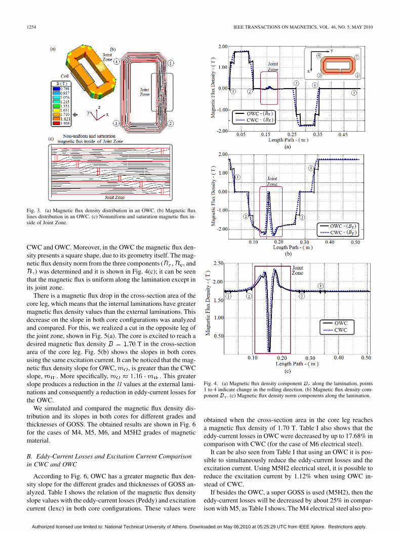
The magnetic flux density in CWC is shown in Fig. 2. Forthis simulation we used GOSS M5 (0.30 mm). We excite thecore to reach an average T in the core cross sec-tion. This value is our reference value that permitted the com-parison and verification with the eddy losses calculated with thevalues specified by the GOSS manufacturer; for example in theM5 case for T the maximum core loss specified bythe manufacturer is about 1.83 W/kg, but only about 73% ofthis value could be considered eddy losses [18]. Fig. 2(a) showsthat the magnetic flux density is smaller and useless in the cor-ners of the CWC, and from this conclusion, it is possible to trimthe CWC, thereby reducing the cost of manufacturing and im-proving the transformer efficiency through innovate core designOWC [4]. Fig. 2(b) shows the magnetic flux lines distribution ina CWC and Fig. 2(c) illustrates the magnetic flux distribution inits joint zone, where the magnetic flux distortion is evident. This
Fig. 2. (a) Magnetic flux density distribution in a CWC. (b) Magnetic flux linesdistribution in a CWC. (c) Nonuniform and saturation magnetic flux inside ofJoint Zone.
magnetic flux distribution on the CWC was compared with theresults obtained for the OWC, using the same GOSS (M5), andthe same excitation. Fig. 3(a) shows the magnetic flux densityin an OWC. It is evident that the magnetic flux density increaseswith respect to the CWC values [see Figs. 2(a) and 3(a)]. Thesame excitation current produces a T in the OWC,and T in the CWC. This means that an OWC is ableto reach greater magnetic flux density than the CWC using thesame excitation current. Therefore, it is possible to get a reduc-tion in the excitation current of OWC to obtain the same mag-netic flux density. This reduction in the excitation current is be-cause the core length in an OWC is smaller than in the CWCand this causes a reduction of core reluctance.
However, there is an inconvenience in the OWC with respectto the CWC: there is a bigger zone in the OWC in the interiorframe corner where the magnetic flux density raises to saturationvalues (in this example T). Figs. 2(c) and 3(c) showthat there is no significant difference between the magnetic fluxin the joint zone of both CWC and OWC configurations. Wecompared also the magnetic flux density along the lamination.For this we made a path along the lamination in the middle ofone random lamination. We denoted the rolling direction changeby the consecutive numbers 1 to 4 clearly specified in Figs. 2(b)and 3(b). The transformer coils are in the opposite leg to thejoint zone.
Figs. 4(a) and (b) show the magnetic flux density componentand , respectively, along the lamination, and Fig. 4(c)
presents the norm of the magnetic flux density. The was alsodetermined, however, it was found that its magnitude was neg-ligible in comparison with and components, which isreasonable since component is perpendicular to the rollingplane. It can be observed from Figs. 4(a) and (b) that and
components have only a small difference on magnitude for
Authorized licensed use limited to: National Technical University of Athens. Downloaded on May 06,2010 at 05:25:29 UTC from IEEE Xplore. Restrictions apply.
1254 IEEE TRANSACTIONS ON MAGNETICS, VOL. 46, NO. 5, MAY 2010
Fig. 3. (a) Magnetic flux density distribution in an OWC. (b) Magnetic fluxlines distribution in an OWC. (c) Nonuniform and saturation magnetic flux in-side of Joint Zone.
CWC and OWC. Moreover, in the OWC the magnetic flux den-sity presents a square shape, due to its geometry itself. The mag-netic flux density norm from the three components ( and
) was determined and it is shown in Fig. 4(c); it can be seenthat the magnetic flux is uniform along the lamination except inits joint zone.
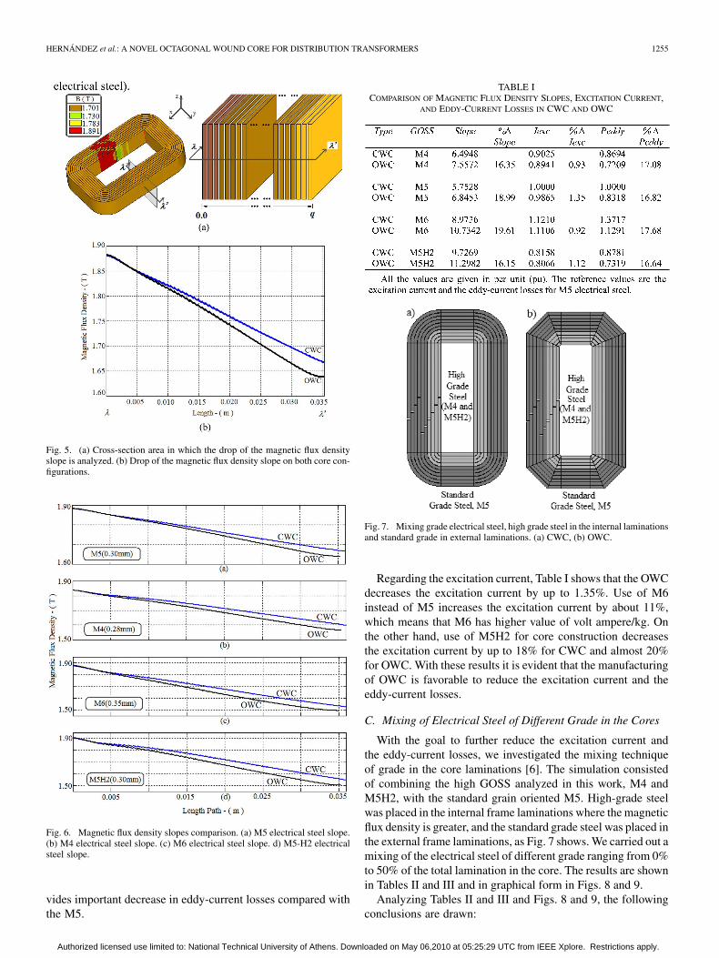
There is a magnetic flux drop in the cross-section area of thecore leg, which means that the internal laminations have greatermagnetic flux density values than the external laminations. Thisdecrease on the slope in both core configurations was analyzedand compared. For this, we realized a cut in the opposite leg ofthe joint zone, shown in Fig. 5(a). The core is excited to reach adesired magnetic flux density T in the cross-sectionarea of the core leg. Fig. 5(b) shows the slopes in both coresusing the same excitation current. It can be noticed that the mag-netic flux density slope for OWC, , is greater than the CWCslope, . More specifically, . This greaterslope produces a reduction in the values at the external lami-nations and consequently a reduction in eddy-current losses forthe OWC.
We simulated and compared the magnetic flux density dis-tribution and its slopes in both cores for different grades andthicknesses of GOSS. The obtained results are shown in Fig. 6for the cases of M4, M5, M6, and M5H2 grades of magneticmaterial.
B. Eddy-Current Losses and Excitation Current Comparisonin CWC and OWC
According to Fig. 6, OWC has a greater magnetic flux den-sity slope for the different grades and thicknesses of GOSS an-alyzed. Table I shows the relation of the magnetic flux densityslope values with the eddy-current losses (Peddy) and excitationcurrent (Iexc) in both core configurations. These values were
Fig. 4. (a) Magnetic flux density component � along the lamination, points1 to 4 indicate change in the rolling direction. (b) Magnetic flux density com-ponent � . (c) Magnetic flux density norm components along the lamination.
obtained when the cross-section area in the core leg reachesa magnetic flux density of 1.70 T. Table I also shows that theeddy-current losses in OWC were decreased by up to 17.68% incomparison with CWC (for the case of M6 electrical steel).
It can be also seen from Table I that using an OWC it is pos-sible to simultaneously reduce the eddy-current losses and theexcitation current. Using M5H2 electrical steel, it is possible toreduce the excitation current by 1.12% when using OWC in-stead of CWC.
If besides the OWC, a super GOSS is used (M5H2), then theeddy-current losses will be decreased by about 25% in compar-ison with M5, as Table I shows. The M4 electrical steel also pro-
Authorized licensed use limited to: National Technical University of Athens. Downloaded on May 06,2010 at 05:25:29 UTC from IEEE Xplore. Restrictions apply.
HERNÁNDEZ et al.: A NOVEL OCTAGONAL WOUND CORE FOR DISTRIBUTION TRANSFORMERS 1255
Fig. 5. (a) Cross-section area in which the drop of the magnetic flux densityslope is analyzed. (b) Drop of the magnetic flux density slope on both core con-figurations.
Fig. 6. Magnetic flux density slopes comparison. (a) M5 electrical steel slope.(b) M4 electrical steel slope. (c) M6 electrical steel slope. d) M5-H2 electricalsteel slope.
vides important decrease in eddy-current losses compared withthe M5.
TABLE ICOMPARISON OF MAGNETIC FLUX DENSITY SLOPES, EXCITATION CURRENT,
AND EDDY-CURRENT LOSSES IN CWC AND OWC
Fig. 7. Mixing grade electrical steel, high grade steel in the internal laminationsand standard grade in external laminations. (a) CWC, (b) OWC.
Regarding the excitation current, Table I shows that the OWCdecreases the excitation current by up to 1.35%. Use of M6instead of M5 increases the excitation current by about 11%,which means that M6 has higher value of volt ampere/kg. Onthe other hand, use of M5H2 for core construction decreasesthe excitation current by up to 18% for CWC and almost 20%for OWC. With these results it is evident that the manufacturingof OWC is favorable to reduce the excitation current and theeddy-current losses.
C. Mixing of Electrical Steel of Different Grade in the Cores
With the goal to further reduce the excitation current andthe eddy-current losses, we investigated the mixing techniqueof grade in the core laminations [6]. The simulation consistedof combining the high GOSS analyzed in this work, M4 andM5H2, with the standard grain oriented M5. High-grade steelwas placed in the internal frame laminations where the magneticflux density is greater, and the standard grade steel was placed inthe external frame laminations, as Fig. 7 shows. We carried out amixing of the electrical steel of different grade ranging from 0%to 50% of the total lamination in the core. The results are shownin Tables II and III and in graphical form in Figs. 8 and 9.
Analyzing Tables II and III and Figs. 8 and 9, the followingconclusions are drawn:
Authorized licensed use limited to: National Technical University of Athens. Downloaded on May 06,2010 at 05:25:29 UTC from IEEE Xplore. Restrictions apply.

1256 IEEE TRANSACTIONS ON MAGNETICS, VOL. 46, NO. 5, MAY 2010
Fig. 8. Excitation current as a function of the percentage of grade steel mixed,given in Tables II and III. Curves 1 and 2 show the results for an OWC, whilecurves 3 and 4 present the results for a CWC. The reference values are the ex-citation current for M5 electrical steel.
Fig. 9. Eddy-current losses as a function of the percentage of grade steel mixed,given in Tables II and III. Curves 1 and 2 show the results for an octagonal core,while curves 3 and 4 present the results for a wound core. The reference valuesare the eddy-current losses for M5 electrical steel.
TABLE IICOMPARISON OF EXCITATION CURRENT AND EDDY-CURRENT LOSSES IN CWC
AND OWC FOR MIXING M4 & M5
1) The excitation current is decreased in both cores with theincrease of the percentage mixed of different grades ofGOSS.
2) The mixing technique of different grades of GOSS is morebeneficial for a CWC than for an OWC, in order to reducethe excitation current (curves 3 and 4 of Fig. 8).
3) The mixing of M4 and M5 in an OWC has a minimum ef-fect in order to reduce the eddy-currents (curve 1 of Figs. 8and 9).
4) The eddy-current losses are decreased in both cores withthe increase of the percentage mixed of different grades
TABLE IIICOMPARISON OF EXCITATION CURRENT AND EDDY-CURRENT LOSSES IN CWC
AND OWC FOR MIXING M5H2 AND M5
of GOSS, except for the case when the percentage mixedexceeds the 40%–60% in an OWC.
5) The best mixing to decrease the excitation current is therelation 50% M5H2–50% M5 in a CWC, which providesa reduction of about 33%.
6) The best mixing to decrease the eddy-current losses is therelation 40% M5 H2–60% M5 in an OWC, which providesa reduction of about 28%.
IV. CONCLUSION
This paper investigates the OWC with the aim to reduce theexcitation current and the eddy-current losses. The analysis andsimulation results introduced in this paper show the advantagesof the OWC in comparison with the CWC in terms of reducedexcitation current and eddy-current losses. Moreover, this paperinvestigates the mixing of GOSS of different grades in OWC,which mixing can be much easier implemented for the OWCthan the CWC technology.
The results show that the OWC decreases the eddy-currentlosses by about 16% and the excitation current by 1.3%. It hasbeen also found that the GOSS mixing technique in the CWCis more beneficial to decrease eddy-current losses and excita-tion current than in the OWC. The mixing of high grades ofGOSS in the internal laminations with standard grades of GOSSreduces considerably the eddy-current losses. The reduction ofeddy-current losses and excitation current depends on the per-centage of GOSS steel mixed. The research work and the resultspresented in this paper are very useful for the design and man-ufacturing of transformer cores.
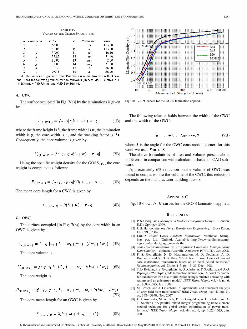
APPENDIX AVALUES OF CORE DESIGN PARAMETERS
Table IV Shows the Values of the 16 Core Design Parameters.
APPENDIX BCALCULATION OF WEIGHT AND MEAN LENGTH OF WOUND
CORES
The following equations are used to determine the coreweight and the core mean length for the analyzed core con-figurations. These equations have been verified with computeraided design (CAD) software as well as with measurements.
Authorized licensed use limited to: National Technical University of Athens. Downloaded on May 06,2010 at 05:25:29 UTC from IEEE Xplore. Restrictions apply.
HERNÁNDEZ et al.: A NOVEL OCTAGONAL WOUND CORE FOR DISTRIBUTION TRANSFORMERS 1257
TABLE IVVALUES OF THE DESIGN PARAMETERS
A. CWC
The surface occupied [in Fig. 7(a)] by the laminations is givenby
(1B)
where the frame height is , the frame width is , the laminationwidth is , the core width is , and the stacking factor is .Consequently, the core volume is given by
(2B)
Using the specific weight density for the GOSS, , the coreweight is computed as follows:
(3B)
The mean core length for a CWC is given by
(4B)
B. OWC
The surface occupied [in Fig. 7(b)] by the core width in anOWC is given by
(5B)
The core volume is
(6B)
The core weight is
(7B)The core mean length for an OWC is given by
(8B)
Fig. 10. �–� curves for the GOSS lamination applied.
The following relation holds between the width of the CWCand the width of the OWC:
(9B)
where is the angle for the OWC construction corner; for thiswork we used .
The above formulations of area and volume present about% error in comparison with calculations based on CAD soft-
ware.Approximately 6% reduction on the volume of OWC was
found in comparison to the volume of the CWC; this reductiondepends on the manufacturer building factors.
APPENDIX C
Fig. 10 shows – curves for the GOSS lamination applied.
REFERENCES
[1] P. S. Georgilakis, Spotlight on Modern Transformer Design. London,U.K.: Springer, 2009.
[2] J. H. Harlow, Electric Power Transformer Engineering. Boca Raton,FL: CRC, 2004.
[3] CRGO Wound Cores Products Information, Vardhman Stamp-ings pvt. Ltd. [Online]. Available: http://www.vardhmanstamp-ings.com/product_crgo_wounds.thm
[4] Aem Unicore-Innovation in Transformer Cores and ManufacturingData Catalog. Gillman, Australia: Aem cores PTY, LTD., Oct. 2008.
[5] P. S. Georgilakis, N. D. Hatziargyriou, N. D. Doulamis, A. D.Doulamis, and S. D. Kollias, “Prediction of iron losses of woundcore distribution transformers based on artificial neural networks,”Neurocomputing, vol. 23, no. 1–3, pp. 15–29, Dec. 1998.
[6] T. D. Kefalas, P. S. Georgilakis, A. G. Kladas, A. T. Souflaris, and D. G.Paparigas, “Multiple grade lamination wound core: A novel techniquefor transformer iron loss minimization using simulated annealing withrestarts and an anisotropy model,” IEEE Trans. Magn., vol. 44, no. 6,pp. 1082–1085, Jun. 2008.
[7] M. Breschi and A. Cristofolini, “Experimental and numerical analysisof stray field from transformers,” IEEE Trans. Magn., vol. 43, no. 11,pp. 3984–3990, Nov. 2007.
[8] E. I. Amoiralis, M. A. Tsili, P. S. Georgilakis, A. G. Kladas, and A.T. Souflaris, “A parallel mixed integer programming-finite elementmethod technique for global design optimization of power trans-formers,” IEEE Trans. Magn., vol. 44, no. 6, pp. 1022–1025, Jun.2008.
Authorized licensed use limited to: National Technical University of Athens. Downloaded on May 06,2010 at 05:25:29 UTC from IEEE Xplore. Restrictions apply.
1258 IEEE TRANSACTIONS ON MAGNETICS, VOL. 46, NO. 5, MAY 2010
[9] S. L. Ho, Y. Li, R. Y. Tang, K. W. E. Cheng, and S. Y. Yang, “Calcula-tion of eddy current field in the ascending flange for the bushings andtank wall of a large power transformer,” IEEE Trans. Magn., vol. 44,no. 6, pp. 1522–1525, Jun. 2008.
[10] G. Stumberger, S. Seme, B. Stumberger, B. Polajzer, and D. Dolinar,“Determining magnetically nonlinear characteristics of transformersand iron core inductors by differential evolution,” IEEE Trans. Magn.,vol. 44, no. 6, pp. 1570–1573, Jun. 2008.
[11] J. V. Leite, A. Benabou, N. Sadowski, and M. V. F. da Luz, “Finiteelement three-phase transformer modeling taking into account a vectorhysteresis model,” IEEE Trans. Magn., vol. 45, no. 3, pp. 1716–1719,Mar. 2009.
[12] E. I. Amoiralis, P. S. Georgilakis, M. A. Tsili, and A. G. Kladas,“Global transformer optimization method using evolutionary designand numerical field computation,” IEEE Trans. Magn., vol. 45, no. 3,pp. 1720–1723, Mar. 2009.
[13] O. Biro, K. Preis, and K. R. Richter, “Various FEM formulations forthe calculation of transient 3D eddy currents in nonlinear media,” IEEETrans. Magn., vol. 31, no. 3, pp. 1307–1312, May 1995.
[14] ANSYS Reference Manual, 8th ed. Canonsburg, PA: SAS IP INC.,2003.
[15] N. A. Demerdash and D. H. Gillott, “A new approach for determinationof eddy currents and flux penetration in nonlinear ferromagnetic mate-rials,” IEEE Trans. Magn., vol. MAG-10, no. 3, pp. 682–685, 1974.
[16] J. Xu, A. Lakhsasi, Z. Yao, and V. Rajagopalan, “A practical modelingmethod for eddy-current losses computation in laminated magneticcores,” in Proc. IEEE 31st Industry Applications Soc. Annu. Meet.,Oct. 1996, vol. 3, pp. 1532–1537.
[17] A. Bermudez, D. Gomez, and P. Salgado, “Eddy-current losses in lam-inated cores and the computation of an equivalent conductivity,” IEEETrans. Magn., vol. 44, no. 12, pp. 4730–4738, Dec. 2008.
[18] Armco Oriented and Tran-Cor H Electrical Steels Data Catalog.Middletown, Ohio: Armco Steels Inc., 1979.
Iván Hernández (S’06) was born in Salamanca, Guanajuato, México, in 1979.He received the B.Sc. degree in electrical engineering from the University ofGuanajuato, Mexico, in 2002, and the M.Sc. degree in electrical engineeringfrom the CINVESTAV Guadalajara, México, in 2005. He is a Ph.D. student atCINVESTAV Guadalajara and currently a visitor at Polytechnic Institute of NewYork University.
He was an electrical engineer designer for two years in FMS Ingeniería,Guadalajara, México. His research interests are the numerical analysis applied
to electrical machine design, and software simulation tools particularly for elec-tromagnetic fields.
Juan Carlos Olivares-Galván (M’04) was born in Michoacán, México, in1969. He received the B.Sc. and M.Sc. degrees in electrical engineering fromInstituto Tecnológico de Morelia, Mexico, in 1993 and 1997, respectively, andthe Ph.D. degree in electrical engineering from CINVESTAV, Guadalajara,México, in 2003.
He is currently a Professor at the Departamento de Energía of UniversidadAutónoma Metropolitana (UAM). He was with Electromanufacturas S.A. deC.V., where he was a transformer design engineer for eight years. He was aVisiting Scholar at Virginia Tech, Blacksburg, in 2001. His main interests arerelated to the experimental and numerical analysis of transformers.
Pavlos S. Georgilakis (M’01) was born in Chania, Greece, in 1967. He receivedthe Diploma in electrical and computer engineering and the Ph.D. degree fromthe National Technical University of Athens (NTUA), Athens, Greece, in 1990and 2000, respectively.
He is currently a Lecturer at the School of Electrical and Computer Engi-neering of NTUA. From 2004 to 2009, he was an Assistant Professor in theProduction Engineering and Management Department of the Technical Univer-sity of Crete, Greece. From 1994 to 2003, he was with Schneider Electric AE,where he worked in the transformer industry as transformer design engineer forfour years, and research and development manager for three years. He is theauthor of the book Spotlight on Modern Transformer Design (Springer, 2009).His current research interests include transformer design and power systemsoptimization.
Jose Manuel Cañedo (M’96) was born in Mazatlan, Sinaloa, Mexico, in 1950.He received the B.Sc. degree from the University of Guadalajara in 1971, theM.Sc. degree in electrical engineering from the National Polytechnic Institute(IPN) of Mexico in 1980, and the Ph.D. degree from the Moscow Power Insti-tute, URSS, in 1985.
From 1988 to 1994, he was a researcher at CFE Mexico. From 1994 to 1997,he was at the University of Guadalajara and since 1997, he has been with CIN-VESTAV Guadalajara Campus, Mexico, as a Professor in the graduate programsin Electrical Engineering. His research interests include nonlinear robust con-trol of power systems, electric machines, and electromagnetic fields.
Authorized licensed use limited to: National Technical University of Athens. Downloaded on May 06,2010 at 05:25:29 UTC from IEEE Xplore. Restrictions apply.