a null test for null correctors: error analysis proc... · a layout of the cgh null test, shown in...
TRANSCRIPT

A null test for null correctors: error analysis
Jim BurgeSteward Observatory Mirror Laboratory, University of Arizona
Tucson, Arizona 85721
ABSTRACT
An optical test has been devised to test and qualify null correctors that are used formeasuring highly aspheric primary mirrors. The technique employs a rotationallysymmetric computer-generated hologram (CGH) that tests the null corrector directly bysynthesizing a wavefront that would be returned by a perfect priznaiy mirror. A descriptionof the test and summary of the error analysis are given. The error analysis includeshologram errors from pattern distortion, substrate flatness, and etch depth variations. Italso includes the effects of errors in the wavelength and data analysis errors. This resultinganalysis shows ppm accuracy for measuring the conic constant of null correctors builtfor measuring 3.5-rn f/l.75 primary mirrors.
1. INTRODUCTION
Aspheric optical surfaces are often measured using null correctors to allpw a null mterferometric test. Since the opticalsurfaces are fabricated based on the results ofthe test, the null correctors define the shapes ofthe final optics. There is always apossibility that the null corrector could be flawed, resulting in the final shape of the optic being incorrect. Two recenttelescopes had their primaiy mirrors made to the wrong shape because of errors in the null correctors - the Hubble SpaceTelescope' and the European New Technology Telescope. If accurate testing of the null correctors had been performed, theerrors would have been discovered and corrected in the shop. Instead, the errors were not discovered until the finished mirrorswere in their operational telescopes.
A new, highly accurate test for null correctors is described that uses circularly symmetric computergenerated holograms. Thispaper gives a general description and error analysis of this new method of testing null correctors. The derivations are givenmore completely by Burge, also the results and more detailed analyses of actual measurements are given in another pap&.Some useful background information on CGH and optical testing is given in Section 2. The design and fabrication of thehologram are described in Section 3. An error analysis is presented in Section 4 that includes errors in the fabrication of theCGH, errors in performing the test, and errors in the data analysis. The CGH null lens test was successfully performed on nullcorrectors for two 3.5-rn /11.75 primary mirrors, and the error analysis for these tests is given as an example in Section 5.
In the CGH null lens test, a computergenerated hologram of the mirror is tested by the null lens. The hologram is made so itwill appear to the test lenses as if it were a perfect primary mirror. The test is insensitive to alignment errors, and uses nooptics other than the hologram. The hologram is designed and fabricated independently from the null corrector, so agreementbetween the two indicates a high probability that both are correct.
The hologram is simply a circular grating or reflective zone plate fabricated onto a flat glass substrate. The holograms used atSteward Observatoiy were made by etching concentric grooves into fused silica substrates and coating with reflectivealuminum. The CGH patterns were fabricated using electron beam lithography that has been developed for the production ofintegrated circuits. The spacing of the grooves is determined analytically to synthesize a wavefront reflected by a perfectminor. The groove depth and width are optimized to minimize fabrication costs while giving the correct intensity of thediffracted light.
86 / SP!E Vol. 1993 0-8 194-1242-2/93/$6.0O

A layout of the CGH null test, shown in Fig. 1, depictsan Offner null lens3'5 and CGH. No modifications aremade to the null lens for performing this test; the nullcorrector tests the hologram exactly as if a real mirrorwas being measured. The use of the hologram to testthe null corrector is surprisingly simple. The CGH ispositioned at the paraxial focus of the null corrector.Once the CGH is near the correct position, the shapeof the fringes in the interferometer is used to align thehologram. Since the CGH appears to the nullcorrector to be a complete primaiy mirror th thecorrect shape, the alignment of the hologram is exactlylike that of the actual primary. The lateral translation,axial translation, and tilt of the null lens are adjustedto eliminate tilt, focus, and coma from theinterferogram.
The azimuthal errors in the holograms were removedfrom the null lens measurements by averaging manydata maps taken th the CGH at different rotationalpositions. When an average of many maps is takenwith the CGH at equally spaced rotational positions,the non-axisymmetric errors in the CGH average outwhile the errors in the null lens remain. it is easy torapidly make many measurements with the CGHbecause of the short optical path length.
NULL CORRECTOR
HOLOGRAM
Figure 1. Layout of CGH test of null lens. The use of the CGHinvolves simply positioning the hologram at the correct locationand making the measurement as if testing the mirror itself.
The holograms are designed to give about 4% diffraction efficiency into the desired order. This matches the intensity from thereference surface to give a high-contrast interference pattern. A pinhole positioned near the Shack cube rejects the stray ordersof diffraction and lets only the desired order through. The size ofthe pinhole is optimized so that the area corresponding to theentire tested region ofthe mirror is free from spurious orders, but the spatial frequency cutoff is acceptable.
2. OPTICAL TESTING WITH COMPUTERGENERATED HOLOGRAMS
2. 1 . BACKGROUND ON CGH AND OPTICAL TESTINGOptical testing of aspheric surfaces using computer-generated holograms (CGffs) has been used for over twenty years. Anexcellent summary of CGH optical testing is given by Loomis6. Some more recent work in the field is given in a thoroughreview by Creath and Wyant7.
A hologram is generally used to modulate the phase or amplitude of a wavefront, causing it to propagate such that it forms adesired phase front or intensity distribution. A photographically produced hologram may be used to store and play back anexisting wavefront8. Synthetic holograms may also be specified by a computer and written with an electronic plotter9. Thecomputer-generated hologram is a diffraction grating that uses a spatial variation in ruling frequency to create a desired changein wavefront. The CGH may be interpreted as changing ray directions according to the grating equation,
where °O' O,, = incident and diffracted angle
s(sin 9o + Sfl 9m)= mZ(1)
A, =wavelengthm order of diffractions = local ruling center-to-center spacing.
SPIE Vol. 1993/87
SHACK CUBEINTERFEROMETER
Equivalently, the hologram changes the wavefront phase. When used in mth order, the CGH adds m waves of optical path tothe wavefront for each ruling cycle.
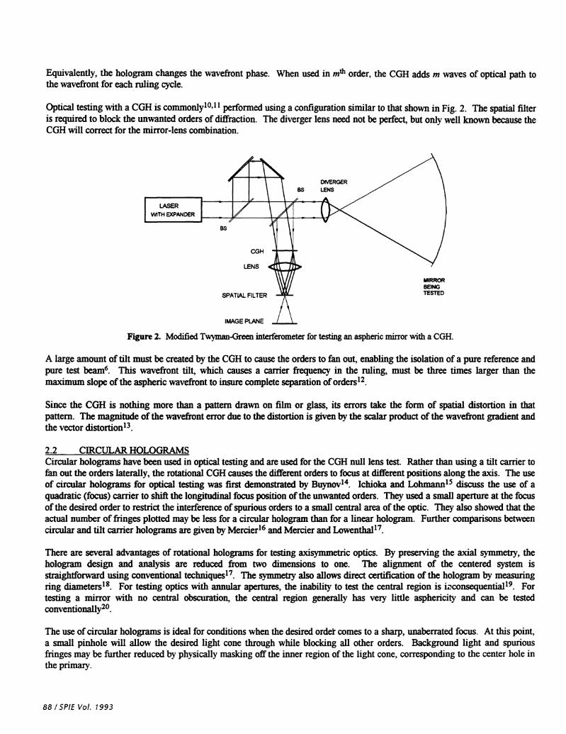
Optical testing with a CGH is commonly10'1' performed using a configuration similar to that shown in Fig. 2. The spatial filteris required to block the unwanted orders of diffraction. The diverger lens need not be perfect, but only well known because theCGH will correct for the mirrorlens combination.
LENS
SPATLAL FILTER
IMAGE PLANE
Figure 2. Modified Nyxnan-Green interferometer for testing an asphenc mirror with a CGH.
A large amount oftilt must be created by the CGH to cause the orders to fan out, enabling the isolation of a pure reference andpure test 'j' wavefront tilt, which causes a earner frequency in the ruling, must be three times larger than themaximum slope ofthe aspheric wavefront to insure complete separation of orders12.
Since the CGH is nothing more than a pattern drawn on film or glass, its errors take the form of spatial distortion in thatpattern. The magnitude ofthe wavefront error due to the distortion is given by the scalar product of the wavefront gradient andthe vector distortion13.
2.2 CIRCULAR HOLOGRAMSCircular holograms have been used in optical testing and are used for the CGH null lens test. Rather than using a tilt carrier tofan out the orders laterally, the rotational CGH causes the different orders to focus at different positions along the axis. The useof circular holograms for optical testing was first demonstrated by Buynov14. Ichioka and LlijlS discuss the use of aquadratic (focus) carrier to shift the longitudinal focus position ofthe unwanted orders. They used a small aperture at the focusofthe desired order to restrict the interference of spurious orders to a small central area of the optic. They also showed that theactual number offringes plotted may be less for a circular hologram than for a linear hologram. Further comparisons betweencircular and tilt carrier holograms are given by Mercier16 and Mercier and Lowenthal17.
There are several advantages of rotational holograms for testing axisymmetric optics. By preserving the axial symmetry, thehologram design and analysis are reduced from two dimensions to one. The alignment of the centered system isstraighiforward using conventional techniques17. The symmetry also allows direct certification of the hologram by measuringring diainete&8. For testing optics with annular apertures, the inability to test the central region is iiconsequential19. Fortesting a mirror with no central obscuration, the central region generally has very little asphericity and can be testedconventionally20.
The use of circular holograms is ideal for conditions when the desired order comes to a sharp, unaberrated focus. At this point,a small pinhole will allow the desired light cone through while blocking all other orders. Background light and spuriousfringes may be further reduced by physically masking off the inner region of the light cone, corresponding to the center hole inthe primary.
88/SPIE Vol. 1993
DIVERGER
as LENS
as
CGH
MIRRORBEINGTESTED

The size of the pinhole is optimized to rejectthe stray orders without limiting resolution.The pinhole is positioned at the center ofcurvature of the interferometer referencesurface where the light comes to a sharp focus.Figure 3 shows how a stray order is blocked bythe pinhole. The light from the desired ordercomes to a sharp focus at the pinhole. Theunwanted orders are out of focus and aberratedso they do not make it through the aperture.Since an annular pupil is used, an out-of-focusstray order will cause an annular image. Aslong as the pinhole is smaller than the innerdiameter of this annulus, the light in this strayorder will be completely blocked.
The pinhole may not be made arbitrarily smallhowever because it acts as a low-pass spatialfilter with cutoff spatial frequency derivedusing Fourier optics3'21. For the null lens forthe WIYN 3.5-rn primaiy that uses a 0.332 NAbeam, a 200-jim pinhole gives 30 cycle-per-meter resolution or 105 full cycles across themirror diameter. This frequency optimallymatches the Nyquist sampling rate determinedby the digitization of 200 pixels across themirror. This pinhole also completely rejects allbut the desired orders of diffraction in the clearaperture.
unwanted order
(defocused from pinhole)
Figure 3. Rejection of stray diffraction orders. The order rejection relies ontwo principles. (1) The desired order comes to a sharp focus where all otherorders are out of focus, and (2) An annular pupil is used. There is a centraluntested region that is blocked elsewhere.
3. DESIGN AND FABRICATION OF CGH FOR NULL LENS TEST
3.1. CGH DESIGNThe CGH design is defined only by the shape ofthe primaiy mirror and not any specific null lens. The radial ring positions arechosen based on an exact analytical model of the rays normal to the primaiy mirrors. The normal rays are propagatedanalytically to intersect a plane at the paraxial center of curvature of the mirror. The intercept positions define the mapping ofthe mirror position onto the hologram plane (See Fig. 4.) The path length variation across the mirror defines the hologramphase function. This model gives an exact expression for the wavefront function that the CGH must create to synthesize aperfect primaiy mirror. Approximations are used only for the error analysis.
The exact relationships were expanded in power series and truncated for the error analysis. The following definitions aremade:
r = radialmirror positionR =vertex (paraxial) radius of curvature of mirrorK = conic constant of mirrorx(r) =ray intercept position on hologram corresponding to r on mirror.
The CGH is encoded by specifying a phase function for the diffraction to create. For use in the mth order, this CGH will consistof one plotted fringe for every m waves in the phase function. The holograms for testing the null correctors are used inreflection, so the phase functions must be twice the OPD given above. This gives ring positions for every m x?2 of the OPD.
SPIE Vol. 1993 /89
desired order
mask withaperture at focusof desired order
image of mirrorfrom only theselected order

The shape of the OPD function (see Fig. 5)looks conical with little slope change over most of the CGH. This fortunate shapeallows the CGH to work with no carrier at all. The radial slope in the wavefront itself is sufficient to act as a circular carrierwith ring spacing nearly constant over most of the hologram. The CGH function shown in Fig. 5 shows why the conventionalmethod of specifying CGH functions as a power series with even terms fails to converge for designing this hologram. There isa cusp at the center that is poorly modeled using a power series with a reasonable number of terms.
Mapping of mirror to CGH OPD at CGH
For a hologram at paraxial focus, themirror to the CGH according to
rays map from the The wavefront created by the CGH is approximated as
Kr3x(r)
2R2
3KOPD-8R3
Mapped into CGH coordinates, this takes the form below.
EE
C.,
0.2N0a.NN
NN
0N
I
Kr4Surface Asphere —
8R3
20
10
0
-10
-1000 0 1000radial position on rvrror(mm)
-20 -10 0 10radial position at CGH (mm)
-2000 2000 20
Figure 4. CGH mapping function showing the relationship Figure 5. Wavefront phase function required of a paraxial-focusbetween mirror position and position on hologram. This plot is for CGH to test a null corrector for a 3.5-rn f/l.75 pnmaiy mirror.
a CGH used to test a null corrector for a 3.5-rn ff1.75 primarymirror.
It is interesting that this OPD for the null corrector test has minus three times the aspheric deviation of the primaxy mirror,
(2)
The surface aspheric departure represents the surface deviation from a reference sphere centered at paraxial focus. The aboveOPD is the path difference for a normal ray that intersects the CGH plane.
3.2. CGH FABRICATIONThe fabrication of holograms using electron beam lithography is now quite common1 1,22• There are firms that specialize in theencoding and printing of CGffs. They have software that evaluates a phase function, usually specified with polynomialcoefficients, to create a data file that will drive the plotter. This involves approximating the continuous fringes as chains oftrapezoids that the plotter can directly write3. The error in the approximation is negligible if small enough trapezoids areused.
90/SPIEVoI. 1993

The fabrication of the holograms for testing the null correctors at SOML uses electron beam lithography to write a master,which is then printed to the final substrate. This allows the usual practice of writing the master onto a thin, pre-coated glassslide, while the final CGH is on a thick, optically flat glass substrate. This method can severely limit the accuracy of the CGHifthe printing is flawed. For this reason, it may be preferable to have the final CGH written directly by the c-beam writer.The CGH is contact printed by holding the master in direct contact with the photoresist-coated blank and exposing withcollimated light. The master can be certified as accurate to 15 jim, and the errors from well-controlled contact printing areless than 1 24 Since it is difficult to verify the final printing to sub-micron accuracy, an error in the printing could goundetected, leading to an inaccurate optical test.
By using the CGH in third order, the number of rings required to test a null lens is reduced and the smallest feature size isincreased by a factor of three. This makes the part easier and less costly to fabricate. To get the desired diffraction efficiencyfrom the third order, the CGH is made into a pure phase element by etching grooves into the glass and coating the entiresurface with reflective aluminum.
4. ERROR ANALYSIS
The error terms, as analyzed in this section, originate from three sources: the CGH itsell the implementation of the test, andthe analysis of the data. These terms are described and analyzed below. The derivations are given more completelyelsewhere.
4. 1 . ERRORS FROM FABRICATION OF CGHThe most obvious errors in the CGH null lens test come from the errors in the CGH itself All possible error sources areevaluated and added to estimate the uncertainty in the CGH. The CGH errors can come from the substrate surface figure, ebeam writing errors, printing to the final substrate, or phase etching. They are separated as either figure or hologram errorsdepending on whether the phase error is caused by the surface reflection or diffraction. The figure errors affect the wavefrontfrom all diffracted orders equally, and the effects of the hologram distortion errors are proportional to the order number. Thehologram distortion does not affect the wavefront from the zero-order specular reflection. However, the variations in etchwidth and depth strongly affect the zero-order reflection, but have a minimal effect on the other orders.
4. 1. 1 . SURFACE FLATNESSThe figure error in the hologram surface adds a phase error to the diffracted wavefront that is twice the surface error of theCGH. The wavefront phase errors due to small-amplitude low-frequency figure errors are identical for all diffracted orders. Inthe absence of other errors, this fact would enable the direct measurement of the figure errors using a Fizeau interferometerwith a flat reference. The measured figure errors could then be subtracted from the null lens measurement. However,variations in the etch depth and duty cycle cause irregularities in the zero-order or specular wavefront that are much larger thanthose in the non-zero-order diffracted wavefronts. The flatness of the CGH substrate must be measured before the hologram isapplied. The error in the null lens test due to the CGH surface flatness is quite small. The substrates are specified flat to X/20at 546 nm and the majority of this error is likely to be astigmatism that is removed from the null lens measurement by rotatingthe hologram.
4.1.2. HOLOGRAM DISTORTIONThe most severe errors in this test are the hologram errors consisting of distortion in the ruling pattern. The distortion may becaused by limitations in the e-beam writing or in the printing onto the final substrate. Distortion causes an error in thediffracted wavefront, approximated for the null lens test as
2 rX
(3)R
where, LW = wavefront error (twice surface error in measurement)= radial CGH error (actual radial position of groove -desired position)
SPIEVo!. 1993/91

r virtual radial position in mirror coordinatesR = radius of curvature ofprimaiy mirror.
The first order approximation is independent ofthe order m and wavelength.
The effect ofthe CGH error for the null lens test is analyzed by making the above approximations for W(r) and x(r). The mostsignificant radial error in the CGH is the linear scale of the hologram. A scale error C gives a shift in the patternproportional to radial position, Cx.
This causes the diffracted wavefront to have an error, which is simply spherical aberration W,
(4)R2R2) R3
The conic constant change in the pnmaiy mirror that would cause this W is
4R3LK=——xW=—4KxC. (5)r
This result is interesting; it is only the linear component of the CGH distortion, which is a scale error, that causes an error inthe measured conic constant.
The magnitude of the hologram errors is estimated from knowledge of the encoding, writing, and priming process accuracy.The CGH encoding is performed with sufficient resolution to insure digitization errors less than the ebeam pixel size. The e-beam writers are verified to be accurate to 15 sun. The accuracy of the printing depends on the method used and theexpertise ofthe technician.
The form of the hologram errors determines the type of wavefront errors induced. Most of the encoding and writing errorsoccur over small spatial scales causing high frequency errors that are filtered out25. Since azimuthal errors average out whenrotating the CGH, the error budget must only include spherical aberration. The magnitude of the third-order sphericalaberration (which has a fourth order dependence on r) is estimated by assuming the distortion can cause pure W. Thistranslates into a scale error given by the ratio of the maximum shift ç over the radius of the CGH. The resulting wavefronterror is given by Eq. (4).
The higher.order spherical aberration is assumed to be much smaller than the low-order error described above. The hologramsare written and printed using equipment for making integrated circuits, so the higher-order writing and printing errors shouldhave no tendency to be axisymmetric. An upper limit on the magnitude of the higher-order errors may be obtained assumingall of the grating error occurs where period is minimal. Assuming the maximum distortion occurs near the edge of thehologram, the maximum wavefront error tW is given by
(6)
For the CGH null lens test for a 3.5-zn ff1.75 primaiy mirror, a 0.2 jim maximum hologram error can cause a maximumwavefront error of 56 nmat the edge of the clear aperture.
4.1.3. ETCHING ERRORSVariations in the depth of the etched grooves and the ruling duty cycle must also be considered as potential error sources. Thevariations in duty cycle or errors in the width of the etched grooves cause only variation in diffraction efficiency for the non-zero diffracted orders. These errors do cause phase variations for the zero order diffraction. The etch depth variations cause
92/SPIE Vol. 1993
phase variations for all orders. For grooves nominally 2J4 deep, the wavefront variations are equal to the variations in etchdepth. Groove depth variation of will give wavefront errors of
4.2. ERRORS FROM USE OF CGHA CGH manufactured without figure or writing errors does not guarantee a perfect null lens test. The test of the null correctorwill only give a null result for a flawless null lens and CGH that are designed for the same radius of curvature, conic constant,and wavelength oflight. Also, a change in the temperature of the CGH will cause it to expand and induce spherical aberration.Since the CGH emulates a perfect primary mirror, the alignment does not significantly affect the test accuracy. Noise in themeasurements due to vibration, seeing, random electronic noise, and digital round-off errors are negligible in the average ofmany measurements.
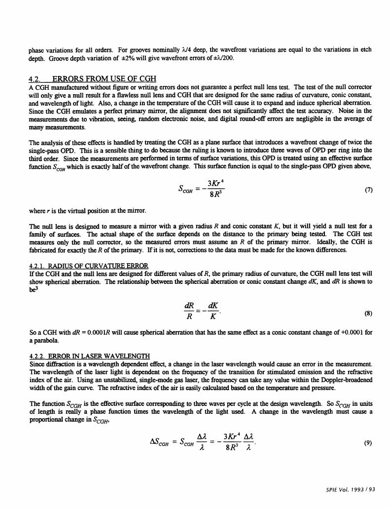
The analysis of these effects is handled by treating the CGH as a plane surface that introduces a wavefront change of twice thesingle-pass OPD. This is a sensible thing to do because the ruling is known to introduce three waves of OPD per ring into thethird order. Since the measurements are performed in terms of surface variations, this OPD is treated using an effective surfacefunction SCGH which is exactly half ofthe wavefront change. This surface function is equal to the single-pass OPD given above,
SCGH —334 (7)
where r is the virtual position at the mirror.
The null lens is designed to measure a mirror with a given radius R and conic constant K, but it will yield a null test for afamily of surfaces. The actual shape of the surface depends on the distance to the priznaiy being tested. The CGH testmeasures only the null corrector, so the measured errors must assume an R of the primary mirror. Ideally, the CGH isfabricated for exactly the R ofthe primary. If it is not, corrections to the data must be made for the known differences.
4.2. 1 . RADIUS OF CURVATURE ERRORlithe CGH and the null lens are designed for different values ofR, the primaiy radius of curvature, the CGH null lens test willshow spherical aberration. The relationship between the spherical aberration or conic constant change dK, and dl? is shown tobe
dR dK(8)
So a CGH with dl? =0.000lR will cause spherical aberration that has the same effect as a conic constant change of +0.0001 fora parabola.
4.2.2. ERROR IN LASER WAVELENGTHSince diffraction is a wavelength dependent effect, a change in the laser wavelength would cause an error in the measurement.The wavelength of the laser light is dependent on the frequency of the transition for stimulated emission and the refractiveindex of the air. Using an unstabiized, single-mode gas laser, the frequency can take any value within the Doppler-broadenedwidth of the gain curve. The refractive index of the air is easily calculated based on the temperature and pressure.
The function SCGH is the effective surface corresponding to three waves per cycle at the design wavelength. So SCGH in unitsof length is really a phase function times the wavelength of the light used. A change in the wavelength must cause aproportional change in SCGH,
i2 3Kr4 2CGH = SCGH
= —
8R3(9)
SPIEVo!. 1993/93

This leads to
LK = 3K—.2 (10)
4.2.3. ALIGNMENT OF CGH TO NULL LENSThe procedure for aligning the CGH to the null lens is identical to the alignment for the null test of primary mirrors. Thelateral translation, axial translation, and tilt of the null lens are adjusted to eliminate tilt, focus, and coma from theinterferograrn. This was derived analytically3 and verified experimentally. The alignment is easily performed to about aneighth of a fringe and the rest is subtracted in software.
4.2.4. RANDOM MEASUREMENT ERRORSThe individual measurements of the CGH have small errors due to environmental effects, electronic noise, digital sampling,and phase calculation errors. These errors become negligible in the average of many measurements since the errors are smallin amplitude and uncorrelated. The environmental effects, caused by air motion in the optical path and vibration, are muchsmaller for the CGH test than they are for the test of the primaiy mirror since the path length is so much shorter for theCGHtest. For a null lens measurement consisting of 15 azimuthal rotations, 5 maps per angle, and 0.O2 rms random errors, therandom component oferror in the average is less than 1.5 urn rms, which is negligible.
4.3 . ERRORS iN DATA REDUCTIONThe last remaining type of error is due to possible errors in the interpretation of the data. This type of error is minimized forthe null test a null result is absolute and requires no interpretation. The actual errors in the null lens and the CGH result in ameasured figure that must be evaluated. Also, known errors in the CGH that are subtracted from the data cause an uncertaintyin the final map from both the CGH errors and the mapping between these errors and the measured data.
The errors in the CGH are calculated in the coordinates at the real mirror. To subtract these from the data, the errors must betransformed into the data coordinates. This transfonnation requires knowing the imaging distortion of the null corrector andthe exact relationship between the edge of the data and the edge of the mirror. The imaging distortion of the null lens ismeasured to about and the edge is determined to within 1 pixel. A computer program was written to remap the CGHerrors according to the imaging distortion, and then fit Zernike polynomial coefficients using least squares. The fitting errordue to distortion was directly assessed by simulating errors in the mapping function. The uncertainty in mapping the CGHerror is independent ofthe uncertainty in the CGH error itseli
5. ERROR ANALYSIS FOR NULL LENS TEST FOR 3.5m fIl.75 PRIMARY MIRRORSTwo null correctors for 3.5-m f/1.5 priniaiy mirrors were measured using the holographic test. The results showed the conicconstants of the null correctors to be correct within the measurement uncertainty of ppm. The error terms that comprisethe measurement uncertainty originate from three sources: the CGH itself, the implementation of the test, and the analysis ofthe data. A single error analysis for two null lens tests was performed taking the worst case from both tests for each error term.
5. 1 . UNCERTAINTIES IN NULL LENS TESTThe errors in the hologram come from the surface figure, groove pattern thstortion, and etch depth variations. The substrateswere specified to be flat to XJ2O P-V. The component of this error that causes pure third-order spherical aberration (fourth-or-der dependence on r) in the null lens test has a cone-shaped appearan&'4. For the error analysis, it was assumed that thiscomponent of the figure error is less than ?J20. The e-beam writer has errors as large as pm and printing errors can beas large as pm. The encoding and digitization errors are not considered because they cause high-frequency errors that donot affect the conic constant. The grooves were specified to be etched to a depth of XJ4 with less than 5% depth variation overthe entire aperture. The error analysis assumes the worst case of 5%depth variation causing pure spherical aberration. Thegross errors discussed below are not included here because they cause phase discontinuities that are easily recognizable.
94/SPIE Vol. 1993

The uncertainty of the laser wavelength has several components. The uncertainty in the laser frequency is determined by thewidth of Dopp1erbroadened gain of the neon transition. The frequency of a single-mode, unstabilized HeNe laser will be473612 1 GHZ26. Errors in the refractive index of air caused by the uncertainty in the temperature and pressure measurementwill cause an error in the wavelength. The thermal expansion of the fused silica holograms will also cause measurement errorsproportional to the temperature difference between fabrication and use.
The errors in thta analysis are due to the uncertainty of the Zernike polynomial fit to the data and the uncertainty of themapping between the mirror and the image. The Zernike polynomial fit of spherical aberration is estimated to be uncertain to
An error in the distortion coefficient of 0.5% would cause an error of 0.0001?. in the 0.06X spherical aberrationcorrection to the WIYN data. A 1% error in the definition of the edge, corresponding to 1 pixel, would cause an additional0.0O24?. error.
These errors are summarized in Table 1 in terms of the uncertainty in the Zernike spherical aberration coefficient Z8 and theconic constant dK. The estimated uncertainty of the test is found by taking a root-sum-square (RSS) of the independent terms.
Table 1. Error budget for CGH null lens measurements for 3.5-rn /11.75 primary mirrors.
Error term Value uncertainty *Z8 (waves) (ppm)
Manufacturing errorswrite errorsprint errorssubstrate flatnessetch depth variations
jim over 20 mm radiusjim over 20 nun radius
?J205% of?./4
0.00540.00720.00830.00 10
3243506
Errors in use
CGH temperaturelaser frequencyair pressureairtemperature
21 C473612 1 GHz697±5 nun Hg21 C
0.00 140.00110.00 100.0011
8666
Data analysis errormapping distortion erroredge definition errorfit error &Z8
6.7 0.5 %1 pixel
0.000 10.00240.0030
1
1418
RSS 0.0131 78
A gross flaw that appears as a sharp step in the diffracted wavefront has been present in several holograms. This error, whichoccurs during the replication of the c-beam written master to the final substrate, is not treated in this analysis. A hologramwith this printing error has the well-defined step that makes the hologram unusable.
5.2. RESULTS FROM TESTING TWO NULL CORRECTORSThe two null correctors for 3.5-rn primary mirrors, for the ARC and WIYN telescopes, were measured at 11 and 15 equallyspaced rotational positions. Small corrections to the data were required to compensate for changes in wavelength and radius ofcurvature between the hologram and null corrector designs. The CGH measurement of the ARC null lens found -11.4 mnspherical aberration corresponding to a conic constant error of -72 ppm. The measured spherical aberration in the W1YN nullcorrector was only -3 nm, corresponding to a conic constant error of -19 ppm. These are within the expected errors of 80 ppm,as determined by the null corrector tolerance analysis.
SPIE Vol. 1993/95

Figure 6. Contour map showing measured null lens error of7.6 urn rms for ARC primary mixror as represented by a 36-tenn Zernike polynomial fit. Surface contours are piotted at 5nm intervals over a range from -20 nm to 20 nrn.
Figure 7. Contour map showing measured null lens error of5.1 nm mis for WIYN primary mirror. The surface errors,computed from a 36-term Zernike fit to the data, are plottedwith contours at 3 urn intervals over a range from -12 urn to 12urn
A visual comparison between measurements of the ARC null lens (Fig. 4)and the WJYN null lens (Fig. 5) shows a strongcorrelation. This is expected because the largest source of error in the null lenses, the refractive index inhomogeneity, is thesame for both systems. The alignment errors are expected to be different.
6. CONCLUSION
A null lens test using a computer-generated hologram is presented including a background on CGH testing, a detaileddescription ofthe CGH null test design and optimization, and a thorough error analysis. This new test works by using the nullcorrector to test a small circular hologram or zone plate that is placed at the paraxial focus of the null lens. The zone platediffracts light back into the -null corrector that precisely matches the light that would be reflected by a perfect primary mirrormany meters away. The CGH null lens test is used to certify a Critical and precise instrument, so a thorough error analysis hasbeen performed. The test has three types of error sources: errors in the CGH, errors in the implementation of the test, anderrors in the interpretation of the results. An effort has been made to understand and minimize all three types of errors.
The test was performed on two null correctors for 3.5-rn mirrors, and it verified the null correctors as having the correct conicconstants within the measurement uncertainty of ppm.
ACKNOWLEDGMENTS
This research was part of the author's Ph. D. dissertation in Optical Sciences at the University of Arizona under Prof. RogerAngel.
96 / SPIE Vol. 1993

L6/1661 7°flIdS
(896L) Z6Z68Z 'L idO jddy 'uw 9 2g sm2uPAM isj UOU-UIflijqjO iiiqionpoithj1 'pmqp&i pu 'uosji j 'ipoj j p 'uUPN N i 'zui u (8861) ZZ-EI 'P88 RIdS °°'d '1021P3 ' H S 'II (ZfdVJ2OlOH pa, V4dUaD-a,flduioJ
U! CSjTSap HO3J UPPOW sotdo '12SaH d c pu 'iaa d 'uunui 0 'siaoj j 'P!3 •1 T 'UUflfl Q V cz (E661) PZZI9tZI 'Z idO jdc!y 4'siq aAtIOIIJIP 2urmnuitp uOiwuruint paoujq :samaj 3rqdi2oqiJJo ojora 'uaia N d
(886L) 9Z-EZ 'P88 3IdS 01d '10!P 'aa'-I H 'S 'II e(ydv.&oloH paJDJaUa-JaJfldWOJ U! 'SUiiOOq uIq-Uo123ap Jo upooua iandwoo dopsaj1 'pioury j s z
(6861) 96E-L8IE 'SZ idO iddV 'uoiouqj uiq uoip .IoJ SWO!Oq pa11aua2 ianduioo Jo uisap papi iandwo3 'isooipj H PU 'UUIppJ j 'SaTL o ''i n s iimnbi s r (8961 '0P1d '1mi-MooN) 's'apd 4aunofJ o uoipnpo.ijuj 'muipoocj '
(o861) 0L9L99 'LI' 11°L idO F AOS 'suIiojoq paz!s1wIics simaui cq sa3J.Ins j3uatjdsJo uqsaj 'AO)pJ y j pirn 'urrrj A V 'ouomi d N o
(cL6L) 6Lt'€ 'Zt' •lPJ idO i AOS 'SWiOjOq 1jnaip iaqus Jo suaui icq 'AO)tJ)J T pU JSflJI •)J 'UI3jIYJ A V 'AOUOUJ d M 'AOU1A 0 61
(6L61) t't'ZLZ '91' •qj •2d0 i os 'saoJins jouaqds utsaijo spotpau' 'misw s i pr urn'1 A V (0861) 9Z-1Z '€T U11U03 id(J 'ursa ouaqds m sumi2ojoi ouanbaij iaui auq-rnjo uosudtuo 'juaio'j S pu iaioia j
(LL6I) t18OZ '9E1 HIdS °°'d 'sio1!p3 'SILZi(} d P" IIuuIsoJD N '(&;lo4afl 0J pa!lddV sozjd0 uo aauaafuoj uvadong js.aj rn 'saj.ms uaids jo 2ursa 3njdiojo "°'N T 91
(zL61) zo9z-L6cz 'ii •dO idd 'swi2ojoq ino.no qji suauoduioo jodo aijo ouauxoiapaiq 'uuuiqo'j y pim onp A ct
(1L61) L6N'61 'si: 4oouqaaj vapd 'saopns ioiiids jo uoiioadsrn uawoiajiaui onjdEiojo4 'oui V u 'mjesn s i 'uiui A v 'AOUOUR'J d N 'AOnH N o Pt
(9L61) S9€ -LP 'Z 3V •2dO 'uoi.suaduioo .iona ptt sisu ioiia :suamap jndo &rnsa ioj swaz2ojoq paiaua-ia2nduio3 'atpiaj j y
(6L61) £66-S86 '9Z ido 'saojins tiids 2msa ioj sumiojoq paiaua-iandwo jni-j 'ou H PU j. •zt
(6861) L.6t-t6L 'ZOI 3tdS °1d 'S10!P ''1 H S P' P!'P"D N 1 'paWJdUaf 4andwo; put, aiivcwdO :sazldQ azqdvi2oo 'wa2oioi paiaua2-ianduio3 qit azaqds u isa o MOHM 'pjOUi }'
(zL61) 6E8Z-I8Z 'H i'O iddV 'SUO1JaAM 3UaqdS sa o suxiooq piaua-ianduioo rnsç 'ijamxa d A P' c r (9961) 696-L96 ' ido idd 'ssw £irnq qi uuau tds xatdwo4 'uuunto'i i v p" uoi .j
(z961) O€1 t-EZII 'ZS 1uIV °S idO f 4'i(ioai UOTOUmUIIUO3 pU S2UO1AM paptU1sUOa', 'S)pmWdfl f P-' P!'1 N 3 •8
1S9-66S dd (z661 'I°A 'N "!!M) 1oip 'up'aj doqg ivaudO UI 'ssa appads UE orqd12ojo 'UThch% ) I P" t1'D )1 1.
(0861) c89-6L,9 '61 1113 idO 1UT2Sa2 j11oI2do pu icqd1112ooq pa1aua8-1a2nduIo34 'S f 'SIUIO(YJ 9
96t) sci-ict 'z do iddV 'siomui jpiojoq.md ioj iopano jinu v 'wo v c
66t) ssaid U 'P661 BIdS 301d 'pa '.iaqo ç 'j upsaj puo &4unpvfnuvyj jvoqd0 paoumtp w 'siomw £ruiud .ioj s.iooanoo jjnu jo uoIIJI2.Ia3 'a8ma H 1 P
(66t 'uoztiyjo i(iS1aAWfl 'saouai,g j11orid(J 'uoi.Iassiu j qj) 'sadoos'apj /vzuiouw .iofsJof.qJyi(.wwu uunsvajyoJsanbzuipaj paaumtp' 'a8in H r i
(1661) EPZ-61Z '8t S312d0 PON f 'iüoiuasqo aq ui (jjiJ adoosapj iojouqo osa ai jo sotido jo aouuuojiad pu dn j soido aA!2OVH '!UOaIPUV 0 pU '1lON '1 'ZU1d 1 't1051!M N 1
0661 'A0N iiodj VSVN iiodai amji11j swasAs joiido adoos1aj. ao1 ajqqn otuaods d 'uouuq j 'Aaupoj y 'sn8uoN U f '!'v d i I 'U11V 1 1
SaDNIUaIaU