a passive thermography approach to bearing condition ... · a passive thermography approach to...
TRANSCRIPT
Mini ReviewVolume 1 Issue 4 - May 2017DOI: 10.19080/JOJMS.2017.01.555567
JOJ Material SciCopyright © All rights are reserved by Wael Moussa
A Passive Thermography Approach to Bearing Condition Monitoring
Wael Moussa*Pharos University in Alexandria, Egypt
Submission: March 24, 2017; Published: June 05, 2017
*Corresponding author: Wael Moussa, Pharos University in Alexandria, Egypt, Tel: ; Email:
IntroductionTemperature monitoring has been adopted for machine
health assessment over the last few decades. Although, most of temperature sensors are designed following similar physical principles, they differ in terms of complexity and precision. Thermography is one of the most advanced methods for temperature monitoring. Traditional systems that monitor the equilibrium temperature have found many applications including food and drug temperature monitoring. However, other applications such as high speed rotary machines need more sensitive health assessment systems that can detect faults in early stages. Therefore, instead of monitoring the equilibrium temperature, the temperature transient behaviour for some applications is used for inspection and non-destructive testing. Transient thermography, which employs pulse surface heating of an inspected component followed by acquisition of the thermal decay, was used for aircraft body inspection [1]. Thermography offers non-contact, wide area detection of subsurface defects, and can be used as an alternative or complement to conventional inspection technologies [2]. Passive thermography has been widely used in production, predictive maintenance, medicine, fire forest detection, building thermal efficiency survey, road traffic monitoring, agriculture and biology, medicine, gas detection and non-destructive testing [2].
Rolling element bearings are widely used machine elements. Their failures are among the most frequently reported reasons for machine breakdowns [3]. Though the vibration-
based approaches have often been used for bearing condition monitoring, they are effective mainly in the detection of physical damages such as cracks and spalls. Such approaches may not be easily used to detect several other undesirable conditions, in particular the lack of lubrication which eventually leads to physical damages of the bearing components. Even though, the vibration-based methods are still the most popular approaches whereas temperature readings are used only for complementary purposes. Recent studies on the application of thermography for bearing fault detection include those in [4,5]. Researchers also worked on the development of wireless sensors for direct measuring bearing cage temperature for bearing fault detection [6-8]. The work related to modeling the thermo-mechanical behaviour of rotating machines or the heat transfer mechanisms inside bearings has also been reported in the literature [9-11]. However, the potential of using temperature monitoring for the detection of both the physical bearing damages and lubrication problems has not yet been adequately addressed. The underlying cause that is hindering the use of thermal information for early fault detection for rotary machines in general and for bearings in particular is yet to be examined.
As such, this paper first examines the factors that contribute to various thermal behaviours of the bearing in operation based on the thermal images taken by a passive thermal camera. The mutual effects of the thermal behaviour and bearing health conditions are analyzed accordingly. A method based
JOJ Material Sci 1(4): JOJMS.MS.ID.555567 (2017) 001
Abstract
Passive thermography is a non-contact monitoring approach with a great potential to be used for early bearing fault detection. However, to date, it has only been used to complement vibration-based approaches. However, the vibration-based methods are effective only in detecting physical damages such as bearing cracks and spalls. They cannot be easily used to monitor other unwanted conditions including the lack of lubrication. As such, this paper proposes a method based on temperature rise differences for the detection of both physical bearing damages and lubrication problems based on the mechanisms of the heat sources generated during a bearing operation as well as the mutual effects between these sources and bearing faults. The performance of the proposed method has been examined experimentally. The results have shown that the proposed method has a promising potential to be used for the detection of both physical bearing damages and lubrication related problems.

How to cite this article: Wael M. A Passive Thermography Approach to Bearing Condition Monitoring. JOJ Material Sci. 2017; 1(4): 555567. DOI: 10.19080/JOJMS.2017.01.555567002
Juniper Online Journal Material Science
on temperature rise differences is then proposed to monitor lubrication conditions and to detect bearing physical damage simultaneously using on-line acquired thermal images. Five bearing conditions, i.e., healthy (reference), inner race fault, outer race fault, reduced lubrication, as well as the combined lubrication shortage and seal distortion are used to examine the performance of the proposed method. Our experimental results have shown that both inner race and outer race bearing faults can be detected within a short period of time. The proposed method has also demonstrated a very promising potential for the detection of lubrication shortage and the combined lubrication and seal problems.
This paper hereafter is organized as follows. In section 2, the sources of the generated heat during bearings operation and the mutual effects between these sources and bearing conditions are explored. Sections 3 and 4 present the experimental setup and experiments procedures. The experimental results are then discussed in section 5. The conclusion of this paper is drawn in section 6.
TheoryTemperature monitoring and detection horizon
The detection horizon is defined as the elapsed time between the first detection of a fault and the resultant mechanical failure [2]. In most mechanical systems a long detection horizon is highly desirable. The longer is the detection horizon, the earlier the faults in mechanical systems can be detected. This early fault detection is required to protect mechanical systems from severe failures. This is especially important for high speed rotary machines in which faults may progress very fast causing catastrophic failures. Temperature monitoring is generally not considered as a preferable condition monitoring method for high speed rotating machinery as it doesn’t have a sufficiently long detection horizon for early fault detection. For this reason, temperature monitoring is not highly ranked in terms of the detection horizon among various fault detection methods [12]. Figure 1 shows the ranking of different fault detection methods regarding the detection horizon. There are two cases for bearing fault occurrence, prior to or during the current operation. In both cases, short detection horizon degrades fault detection system efficiency, as detailed below:
Figure 1: Detection horizons for different fault detection methods [15].
For a pre-existing fault, reaching the steady-state temperature can be preceded by a failure of the system. This is because
reaching steady state or thermal equilibrium temperature may require long time and may exceed several minutes. In high speed rotary machines, a catastrophic failure of the system can occur before reaching this equilibrium state and before the fault is detected.
For an in-process occurring fault, the substantial rise in temperature only occurs in the last stage of component life [13]. In this case, it would not be appropriate to wait till the system equilibrium temperature gives an indication of the fault.
As it can be seen in both cases, temperature monitoring has a slow response for fault detection. The reason of this slow response hasn’t been thoroughly investigated and the methods for addressing this important issue are yet to be developed. The following subsections will examine the sources of generated heat during bearing operation and possible effects of common bearing faults on these heat sources.
Heat sources in antifriction ball bearingsAntifriction ball bearings are commonly used to offer lower
resistance to motion than sliding bearings. However, the heat generated during an antifriction bearing operation is of great importance. Most of this heat is generated by friction torque caused by the resistance to rolling elements rotation. Although, rolling friction or rolling resistance is of small magnitude, it is a complicated phenomenon and does contribute to the temperature rise, particularly in the presence of a fault. The accessible literature has not provided a comprehensive theory for predicting the magnitude of the rolling resistance under all possible conditions of bearing operations due to the complexity of the issue [14]. This complexity is largely attributed to the different natures of sources of friction torque generated during a bearing operation. The generated friction torque represents an energy loss that is mostly converted into heat. The higher the generated friction moment, the higher the energy loss and hence the more heat will be generated during a bearing operation. This torque consists of several constituents that can be considered as different sources of friction torque components of different nature or different sources of heat energy. An equation to calculate the friction torque, encompassing all involved constituents, would be rather complex. The simplest representation of this fiction torque is given as follows [14]:
(1)
Where MF is the total generated friction torque, Mv is the generated torque when the load is zero, mainly due to the drag force caused by lubricant viscosity, MG is the resistance to sliding motion and MD is the damping resistance caused by elastic hysteresis of the material [12].
For the same bearing dimensions and when operating at constant speed and contact angle, both MG and MD depend only on bearing operating load. In this case, the last two terms in Equation (1) can be combined and hence one obtains [13]:

How to cite this article: Wael M. A Passive Thermography Approach to Bearing Condition Monitoring. JOJ Material Sci. 2017; 1(4): 555567. DOI: 10.19080/JOJMS.2017.01.555567003
Juniper Online Journal Material Science
(2)
Where MV is the torque due to lubricant viscous friction it can be calculated using following empirical equations [13].
(3)
Where n is the shaft speed in rpm, VO is the lubricant viscosity in centistoke, dm is the mean diameter of the bearing in millimeters and fo is a factor depends on the type of bearing and the method of lubrication [13]. The above equation shows that the torque due to lubricant viscous friction is constant for bearing operating at low speeds. At moderate to high speeds the torque is proportional to (vo n)(2⁄3) and when the bearing is operating with constant speed, the torque is only proportional to(vo )(2⁄3). M1is the friction torque due to applied load given by:
(4)
Where Fβ is the equivalent load that is depending on the magnitude and direction of the applied load. It can be expressed in equation form as follows for radial ball bearing:
(5)
Where Fa is the axial load, Fr is the radial load and a is the angle of contact Of Equations (5a) and 5(b), the one yielding larger value of Fβ is used. For deep groove ball bearings for which the nominal value for the angle of contact a is zero, the equivalent load is given by:
(6)
f1 In equation (4) is a factor depending on the bearing design and relative bearing load [13].
(7)
where z and y are constants specified based on bearing type and design, FS is the static equivalent load efined as the pure radial or pure axial load that causes the same permenant deformation at the heaviest loaded contact point as that of the applied combined loads, and CS is the bearing static load rating. The bearing basic load rating is defined as the load applied to a non-rotating bearing that will result in a permanent deformation of 0.0001D at the weaker of the inner or outer raceway contacts occurring at the position of the maximum loaded rolling element. D is the rolling element diameter. In the case of radial bearings, Fs=Fβ=Fr Then ,equations (4) and (7) can be combined, resuling in a relation between the friction torque and the load, i.e.,
(8)
Where f2 is a constant depending on bearing size, construction and material, as well as the lubricant characteristic, F is the bearing operating load, and c is the exponent dependent on bearing type and design. It was found empirically that c varies
between 1.0 and 1.2 for roller bearings with good roller guiding, and between 1.2 and 1.6 for various types of ball bearings under different load conditions. The value of c is essentially dependent on the sliding loss caused by the curvature in the contact surfaces. Despite the simplification made on the above equations, they show the sensitivity of the bearing friction torque and generated heat during bearing operation to changes in both lubricant viscosity and applied load. Because of this sensitivity, a small change in these two factors can affect the generated heat in different and sometimes opposite ways. The following subsection shows how the fault can have contradicting effects on the resultant friction torque, and hence on the generated heat during bearing operation.
Fault effect on friction torqueThe above equations (1-8) show that for a given bearing
design and a fixed operating speed, the friction torque will change exponentially with changes of the load and lubricant viscosity. However, the effect of bearing faults on heat generated during bearing operation is not straight forward. This is because different and often opposite effects the same fault can have on different friction torque constituents or friction torque sources. A good example of fault effects on friction sources is the spall on an inner or outer raceway. Although the presence of such a fault can increase the heat generated due to impact energy generated when rolling elements passes over this spall fault, the increase of temperature will decrease the lubricant viscosity. As a result, the net change of a friction torque constituent will depend on the combined effect of the increase in the torque due to the existence of the spall and the decease of the torque caused by the drop in the lubricant viscosity. The challenge in calculating the temperature effect of a bearings fault can also be illustrated when there is a small amount of lubricant leak which leads to two opposite effects on bearing viscous friction Mv. One is the decrease of the drag force caused by reduced lubricant viscosity and the other is increased friction coefficients between the rollers and the raceways due to the lack of lubrication. Obviously, the first effect causes decrease of the generated heat while the second does just the opposite.
The complexity of fault effects on heat generation sources and trends causes the late response of equilibrium temperature to fault occurrence. After the fault becomes matured and the difference of its effects on heat sources gets larger, the generated heat and bearing temperature increase. However, such an increase in equilibrium temperature only happens when the bearing is approaching its end of life [14]. As such, it is not appropriate to monitor bearing conditions based on the rise of the equilibrium temperature. Nevertheless, despite the long time required for the bearing equilibrium temperature to increase, it is observed that the transient behaviour of bearing temperature before reaching equilibrium varies rapidly with the bearing conditions. This observation motivates the development of a new temperature-based bearing fault detection method.

How to cite this article: Wael M. A Passive Thermography Approach to Bearing Condition Monitoring. JOJ Material Sci. 2017; 1(4): 555567. DOI: 10.19080/JOJMS.2017.01.555567004
Juniper Online Journal Material Science
The next section presents our experimental work to examine the different transient temperature behaviours of the faulty and healthy bearings operating under the same speed and load conditions. This result will then be used to detect bearing fault.
Experimental Setup
Figure 2: Bearing test rig.
Figure 3: 1-AC motor (up to 20,000 rpm), 2-Two-step 1566 steel shaft, 3-Anti-vibration flexible couplings (2), 4-Radial load (Disc), 5-Shaft-Hub Locking Device (SHLD).6-Bearing and bearing Housings (2 each), 7-Motor base, 8-Sliding base, 9-HD-810 dynamometer and 10-Sliders (4).
Figure 4: Temperature rise curves for different bearing faults as recorded by thermal camera.
The experiments are conducted on a high speed bearing test rig. The test rig is driven by a high speed motor having a speed range up to 20,000rpm. The speed of the motor is controlled using a SJ-200 Hitachi VFD (variable frequency drive). Six SKF 6202/16 deep groove ball bearings are used for the test. Two of them is kept in healthy condition, the third has an outer race fault, the fourth has an inner race fault, the fifth is short of lubrication and the last one suffers from both lubrication shortage and twisted seal problem. One radial load is supported by a two-step shaft mounted on two bearings. A HD-810 Magtroll dynamometer is connected to the shaft to apply and control torque load. The interfaces between the motor and the shaft and between the dynamometer and the shaft are achieved using high speed anti-vibration flexible couplings. A FLIR E-40 thermal camera is used for thermal video capturing. Figure 2 shows a photo of the test rig and the HD-810 Magtroll dynamometer.
The seeded inner and outer race bearing faults are displayed in Figure 3 respectively. In Figure 4 a schematic drawing for the bearing test rig is presented. The thermal camera is set to record the temperature changes on the bearing side surface by choosing the Rectangle Box option. This option allows recording of maximum and minimum temperatures in the chosen area instead of tracking the temperature of one point done by the Spot option. In order to suppress the high reflection effect of the unwanted areas, the bearing housing and the shaft areas close to the target area are covered by low reflectivity tapes [15,16].
Table 1: Different experimental setup configurations.
Config.No. Configuration Config No. Configuration
1Healthy
bearing at FE side
4Inner race
faulty bearing at DE side
2Healthy
bearing at DE side
5
Bearing with lubricant
problem at DE side
3Outer race
faulty bearing at DE side
6
Seal fault added to a
bearing with lubricant
problem at DE side.
Figure 5
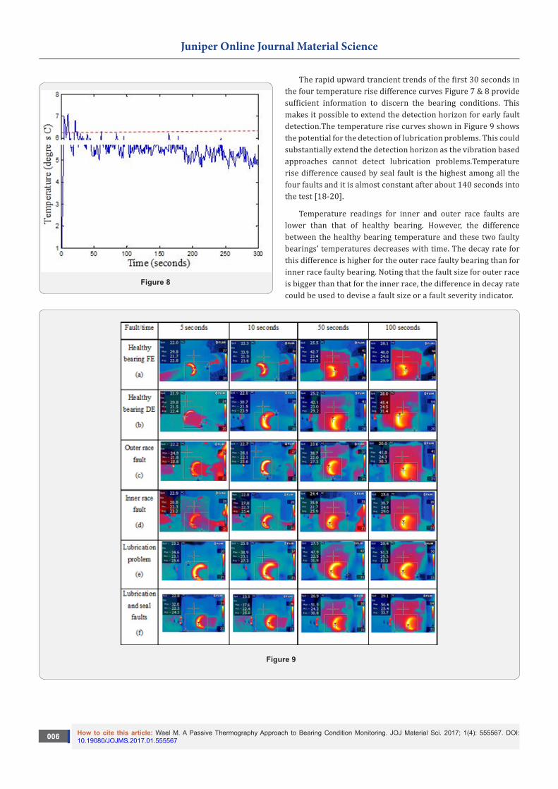
The thermal videos were taken for six different setup configurations as listed in Table 1. A five-minute video is recorded for each configuration while aiming the camera using the Rectangular Box tool on the targeted area as shown in Figure 5. The thermal images at 5, 10, 50 and 100 seconds into the test are also presented in Figure 5 for the four different bearing health conditions. The images for the two healthy bearings located at the drive end (DE, close to the motor) and far end (FE, close to the dynamometer are displayed separately, Then the maximum temperature in the rectangular box tool is sampled at a rate of 1 Hz to draw the temperature rise curve Figure 6. For each

How to cite this article: Wael M. A Passive Thermography Approach to Bearing Condition Monitoring. JOJ Material Sci. 2017; 1(4): 555567. DOI: 10.19080/JOJMS.2017.01.555567005
Juniper Online Journal Material Science
configuration, the temperature rise curve during the transient phase but before the targeted area reaches thermal equilibrium state is plotted in Figure 7. The temperature rise for the healthy bearing at FE is firstly captured and then followed by the healthy bearing at DE. After that, four configurations for the four bearings with different faults are set up. Before seeding the fault, the temperature rise for each bearing of the four faulty bearings is checked with that of its own at healthy condition to assure that the four bearings are identical in terms of their thermal behaviours while they are healthy and hence the difference in their temperature signature after the faults are seeded is due to the fault only. Also, the used lubricant is the same for all bearings and its quantity is also the same except for faults related to lack of lubricant, i.e., configurations #5 and #6. The camera distance and angle with respect to the targeted area in all measurement configurations are kept the same to ensure that the temperature trend change is only caused by bearing faults. The radial disc load is moved during FE bearing filming to a distance equal to the distance between the disc and the DE bearings. This is to maintain the ventilation effect due to disc rotation the same as that on the bearing at DE [17].
Figure 6
Results and Discussion The temperature rise signature is videoed for the six
configurations presented in the previous section. Figure 5 shows four snapshots for each configuration captured at 5, 10, 50 and 100 seconds into the test. The temperature rise curves for the six configurations are shown in Figure 6. The following can be observed from the first glance of the snapshots Figure 5 and trend curves (Figure 6):
• Temperature rise curves for both healthy bearings at DE and FE are almost identical.
• Inner and outer race faulty bearings which can be considered as mechanically faulted bearings
• Have lower temperature rise than the healthy ones.
• Lubricant related faults cause a higher temperature rise than healthy bearings.
The temperature measurements recorded at seven specific times for the six different videoed configurations are listed in Table 2.
Table 2: Temperature readings at selected times.
Bearing Configuration
Healthy bearing FE, temperature oC
Healthy bearing DE, temperature oC
Outer race fault, temperature oC
Inner race fault, temperature oC
Lubrication problem, temperature oC
Lubrication and seal faults, temperature oC
Figure 7
The results show that bearing faults change the temperature rise signature on the bearing side surfaces at the transient stage in different ways. Some faults in their early stages reduces the temperature rise rate [18-20]. This is the case for inner and outer race incipient spall faults. On the other hand, lubrication shortage and the combined lubricant and seal problems cause this rate to increase. Comparing the temperature rise signature curves in Figure 6 can be accomplished by using one of the two curves of healthy bearings as a reference curve as they are practically identical. Then subtracting the curves related to the inner and outer race faults from it leading to the results shown in Figure 7 and subtracting the same reference curve from the curves of the other two faults (i.e., the lack of lubrication plus seal problem, and lack of lubrication only) yields Figure 8. As the behaviors of the two healthy bearings are almost identical, only the results for the four faulty bearings are plotted in the two figures. The following conclusions can be extracted from these two figures.
How to cite this article: Wael M. A Passive Thermography Approach to Bearing Condition Monitoring. JOJ Material Sci. 2017; 1(4): 555567. DOI: 10.19080/JOJMS.2017.01.555567006
Juniper Online Journal Material Science
Figure 8
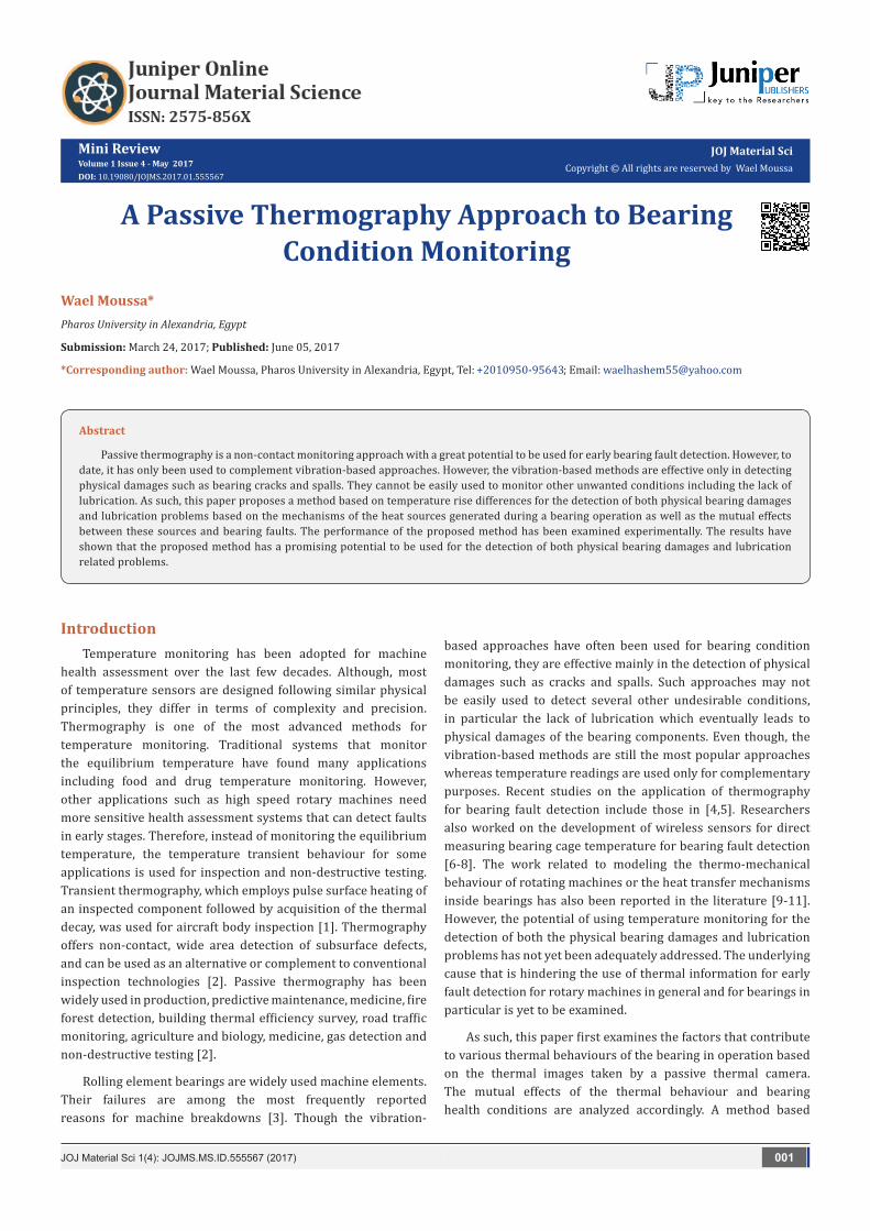
The rapid upward trancient trends of the first 30 seconds in the four temperature rise difference curves Figure 7 & 8 provide sufficient information to discern the bearing conditions. This makes it possible to extend the detection horizon for early fault detection.The temperature rise curves shown in Figure 9 shows the potential for the detection of lubrication problems. This could substantially extend the detection horizon as the vibration based approaches cannot detect lubrication problems.Temperature rise difference caused by seal fault is the highest among all the four faults and it is almost constant after about 140 seconds into the test [18-20].
Temperature readings for inner and outer race faults are lower than that of healthy bearing. However, the difference between the healthy bearing temperature and these two faulty bearings’ temperatures decreases with time. The decay rate for this difference is higher for the outer race faulty bearing than for inner race faulty bearing. Noting that the fault size for outer race is bigger than that for the inner race, the difference in decay rate could be used to devise a fault size or a fault severity indicator.
Figure 9

How to cite this article: Wael M. A Passive Thermography Approach to Bearing Condition Monitoring. JOJ Material Sci. 2017; 1(4): 555567. DOI: 10.19080/JOJMS.2017.01.555567007
Juniper Online Journal Material Science
ConclusionA passive thermography apporach has been proposed for
bearing condition monitoring. The main bearing condition indicator is the trancient behavior of the temperature rise difference at the early stage. The experimental results of five different bearing conditions have demonstated the potential of the proposed method in the detection of both bearing physical damages and lubrication shortage. Consequently, the proposed method can be used for early bearing fault detection because of its capability in monitoring the lubrication problem before it causes physical damages, if the heat generation mechanisms are well understood. It is also observed: a) for most bearing faults in its early stages, the bearing equilibrium temperature approaches its value for healthy bearings; and b) most incipient faults have opposite effects on bearing temperature and can lead to a temperature rise rate that is lower than that of a healthy bearing. These observations explain why most of the temperature monitoring methods have a short detection horizon and lead motivate the development of our method based on the trancient behavior of the temperature rise difference at the early stage. It is worthwhile to point out that the decay rate of temperature difference between the faulty and healthy bearings could be used to device a fault severity index in future.The difference between the temperatures of the bearing that is short of lubricant and the healthy one decreases very slowly and it will take very long time till the temperature for both bearings reach the same equilibrium temperature.
can enhance ambient and high temperature strength, ductility, creep resistance, wear resistance, damping, fatigue, ignition and dry and wet corrosion resistance of magnesium. Similarly, use of metastable/amorphous reinforcement provides another option to enhance hardness, strength and tribological response of magnesium even in micron length scale without significantly affecting ductility unlike their ceramic counterparts. Yet another option is to use hollow reinforcement such as cenospheres (hollow fly ash particles- an industrial waste) which have shown excellent capability to enhance compressive deformation of magnesium. These materials are commonly known as syntactic foams and are targeted for impact prone applications.
While multiple options are available in open literature for expanding the use of magnesium based materials, the bottleneck appears to be the adoption of such technology and up scaling to industrial level. Progress is being made but the pace is slow. It is sincerely hoped that such challenges will be taken up by investors and industrialists to relieve the technological stress imposed on planet earth and its inhabitants.
References1. Plotinkov YA, Winfree WP (2000) Temporal treatment of a thermal
response for defect depth estimation. In: Chimenti DO, Thompson DE
(Eds.), Review of Progress in QNDE AIP. AIP Conference Proceedings, USA, pp. 509-587 .
2. Maldague X (2001) Theory and Practice of Infrared Technology for Non Destructive Testing. John-Wiley & Sons, New Jersey, USA.
3. Randall RB, Antoni J (2011) Rolling element bearing diagnostics-A tutorial. Mechanical Systems and Signal Processing 25(2): 485-520.
4. Wontae KIM, Jinju SEO, Dongpyp H (2012) Infrared Thermographic Inspection of Ball Bearing; Condition Monitoring. In 18th World Conference of Non Destructive Testing 16-20 Durban, South Africa.
5. Seo J, Yoon H, Ha H, Hong H, Kim W (2011) Inferarred thermographic diagnosis mechanism for fault detection of ball bearing under dynamic loading conditions. Advanced materials research 295-297: 1544-1547.
6. Sean Marble, David Tow (2006) Bearing Health Monitoring and Life Extension in Satellite Momentum/Reaction Wheels. IEEEAC paper, USA.
7. Scott S, Kovacs A, Gupta LA, Katz J, Sadeghi F (2011) Wireless Temperature Microsensors Integrated on Bearings for Health Monitoring Applications. In IEEE MEMS, Cancun, Mexico, USA.
8. Jhon AHS, Manuel TQ, Jia Y (2005) Contactless Monitoring of Ball Bearing Temperature. In Instrumentation and Measurement Technology Conference, Ottawa, Canada.
9. Azad D, Ramji K (2012) Identification of bearing assembly defects using Finite Element Analysis and Condition Monitoring Techniques. International Journal of Engineering Research & Technology (IJERT) 1(6): 2278-0181.
10. Cao Y (2006) Modeling of High-Speed Machine-Tool Spindle Systems.
11. Mizuta K (2003) Heat Transfer Characteristics Between Inner and Outer Rings of Heat Transfer. Asian Research 32(1).
12. Stolarski TA, Tobe S (2000) Rolling Contacts. Professional Engineering, London, UK.
13. Harris TA, Kotzalas MN (2007) Advanced Concepts of Bearing Technology. (5th edn), CRC Press, USA.
14. Randall RB (2011) Vibration-Based Condition Monitoring. West Sussex, A John Wiley and sons ltd., New Jersey, USA.
15. Watson MJ, Byngton CS, Behbahani A (2007) Very High Frequency Monitoring System for Engine Gearbox. In 07ATC-268, SAE international conference, doi:10.4271/2007-01-3878.
16. Piersol AG, Paez TL (2010) Harris Shock and Vibration Handbook. (6th edn), New York, USA.
17. Kaplan H (2007) Practical Applications of Infrared Thermal Sensing and Imaging Equipment. (3rd edn), Bellingham, Washington, USA.
18. Patrick R (2009) Diagnostic Enhancements for Air Vehicle HUMS to Increase Prognostic System Effectiveness IEEEAC paper, no. #1608 USA.
19. Rodriguez RI, Jia Y (2011) A wireless inductive-capacitive (L-C) sensor for rotating component temperature monitoring. International Journal on Smart Sensing and Intelligent Systems 4(2).
20. Ashtekar A, Kovacs A, Sadeghi F, Peroulis D (2010) Bearing Cage Telemeter for the Detection of Shaft Imbalance. In IEEE, USA.

How to cite this article: Wael M. A Passive Thermography Approach to Bearing Condition Monitoring. JOJ Material Sci. 2017; 1(4): 555567. DOI: 10.19080/JOJMS.2017.01.555567008
Juniper Online Journal Material Science
Your next submission with Juniper Publishers will reach you the below assets
• Quality Editorial service• Swift Peer Review• Reprints availability• E-prints Service• Manuscript Podcast for convenient understanding• Global attainment for your research• Manuscript accessibility in different formats
( Pdf, E-pub, Full Text, Audio) • Unceasing customer service
Track the below URL for one-step submission https://juniperpublishers.com/online-submission.php
This work is licensed under CreativeCommons Attribution 4.0 LicensDOI: 10.19080/JOJMS.2017.01.555567