the dynamic stability of a rotor passive magnetic bearing with an
TRANSCRIPT

40
�������� � ���������� ����� ���������
���� � ������ �������� � ��� �� ������ ����!����"������ ������"������ ��� �������#����
$ ��%�&'(�)*���%+�,�%�&��,-�,����,-�����&(')��.,�/���'(�)*���%+,)&)-(�����&(')��� )&�,�0��12('�)3��4561���15&0
&���1�26�)���4-2��&1%)2
���������� ���� �������!)&1� 78��)1� 8� 9:89 +''5;<<�=1�)�1)�-<8:1>?@?<2�%+19:89178181?:
��������� ��������$����������������
$
����� �������������� ������������ ����!����"������������"���������������#����
�������
��� � ��� ��������� ��� ����� �������� ������ ����������� ��� ��� ��������� �������� ������� ������ ���� � ������� ��� ��� ���� ������ � � ������ �!����"� #�� ������ ��� �������� ��� ������ ��������� ��� ��� ���$� ��� %�����&����!����� ������ ��� ��� ��������� �������� '��� ���"� ��� �������� �� (� �����!� ��� ��� ���� '��� ����������� � �� ������ "� ��� ����� ��� '�� ��� ������ �������� � � ������ �� ������� �!� ���� ������ ���� ��� ���� ���� ��� ��� �����"��� ������ � �� ������ ���� ��������� ���� ��������� ������� ��������$� ���� ������ ���������'���� ��������"
�������)� ������ �������� ������$� %�����&����!$� �������� � � �����
����*+,� -./��0.� ��1+,��23+,� .� 0.+4#1���25#� ���6#2� %�6��2%�5�0.� 7�+��#23+�� �0-�7� ����#6#3�25#� *#�+#0�
*� ���!� �8�����'���� ����89� �������:'� ��!'����� ;�<!�=�� ������!�8����$� '!=����>� 8�� ����>� �����!� ���&����:'� �=�?�8��!�� ���8� 8� ��8����'���� '!�=� ����?� �=� ��!�������!�� ��!'����� 8�'��8���� ������!�8��&��� '��=�� '� � � � ������'!�"� *� ��� � 8'9=�8���� �8�!'��@�� ������'�A� ;�<!�=�� 8� ��'������ 8� ������:'��'�;!�� 8������'���� ������� %������"� 3� ��8����'���� ��8=;��� ��� ����� ������!�8����� ���� �:<�!�� �8���=�&@�� �8�8���!� �'���8��A� ;�<!�=�"� *!=������ ����!� �!���=� ��!'����� 8�'��8���� ������!�8����"
���� ��������)� ��!'��� ;�<!�=�� ������!�8��$� ������� %������$� 8�'��8���� ������!�8��
��� ���������
Nowadays, permanent magnet types of magnetic bearingsare applied in many applications e.g. non-contact suspen-sions or bearingless drive systems. The passive magneticbearings despite their instability (Earnshaw 1842); not re-strict their technical use, especially in a clean environmentand bio-compliance appliances. The most important ad-vantage of passive magnetic bearings is “zero power” con-trol (Fremerey 1988, Yakushi et al. 2000). The solid magnettype of application has a small size, null friction, and light-weight, high power-factor, high reliability, and efficiency. Inopposite to active magnetic bearings, the permanent-ma-gnets built bearings have no ability to stiffness control be-cause of the static magnetic field. However, they overcomethe active magnetic bearings by an unlimited bandwidth.In the active magnetic bearings, which have negative stiff-ness, energy is consumed to ensure the bias point. While thisbiasing tends to linearize the actuator, the bias current fielditself does no work. Therefore, in many applications passivemagnetic bearings provide the bias field, where external di-sturbances are controlled by magnetic forces generated byactively controlled electromagnets (Wilson and Struder1981, Maslen et al. 1996). The primary advantage of thisconfiguration is the elimination of power loss which is asso-ciated with the generation of the bias field. Other applica-tions are compact-structure active magnetic bearings withsolid magnets e.g. homopolar active magnetic bearings(Ehman et al. 2004). The other rotational machines consistof bearingless electric motors, e.g. permanent magnet syn-
chronous bearingless motors (Satoh et al. 2000, Ohsawa etal. 2000, Redemann et al. 2000a, Redemann et al. 2000b).
In this paper the finite element method model of the pas-sive magnetic bearing (PMB) and the spin tests of the rotormagnetic suspension system based on the PMB were per-formed. The test rig with the magnetic suspension providedby one radial permanent magnetic bearings on one end ofthe rotor is presented. The dynamic model of the radial per-manent magnetic bearing is shown. Next, the discrete mo-del of the PMB is investigated by using the finite elementmethod (FEM). The finite element model was analysed byusing COMSOL Multiphysics software. The magnetic fluxloss and airgap flux density in the case of airgap change arepresented for the Halbach configuration. Also, the nonline-ar effect of the discrete 3D model of the PMB was analyzed.
This work mainly refers to the dynamic stability of passi-ve magnetic suspension and rotor vibration control by thepermanent magnetic bearing. The spin test of the rotor isconducted due to the transient stability of permanent ma-gnets type of the rotor suspension. The rotor was success-fully operated to speed of 4000 rpm. The load capacity ofthe passive magnetic bearing and the vibration damping isdepicted due to the desired unbalanced mass of the rotor.Finally, the experimental tests, analytical calculations, andfinite element results were compared and carried out.
� ��������������������������������
The passive magnetic bearing is designed based on Hal-bach-arrays configuration. The Halbach-array is a special
41
����������������������!)&1� 78� �)1� 8� 9:89
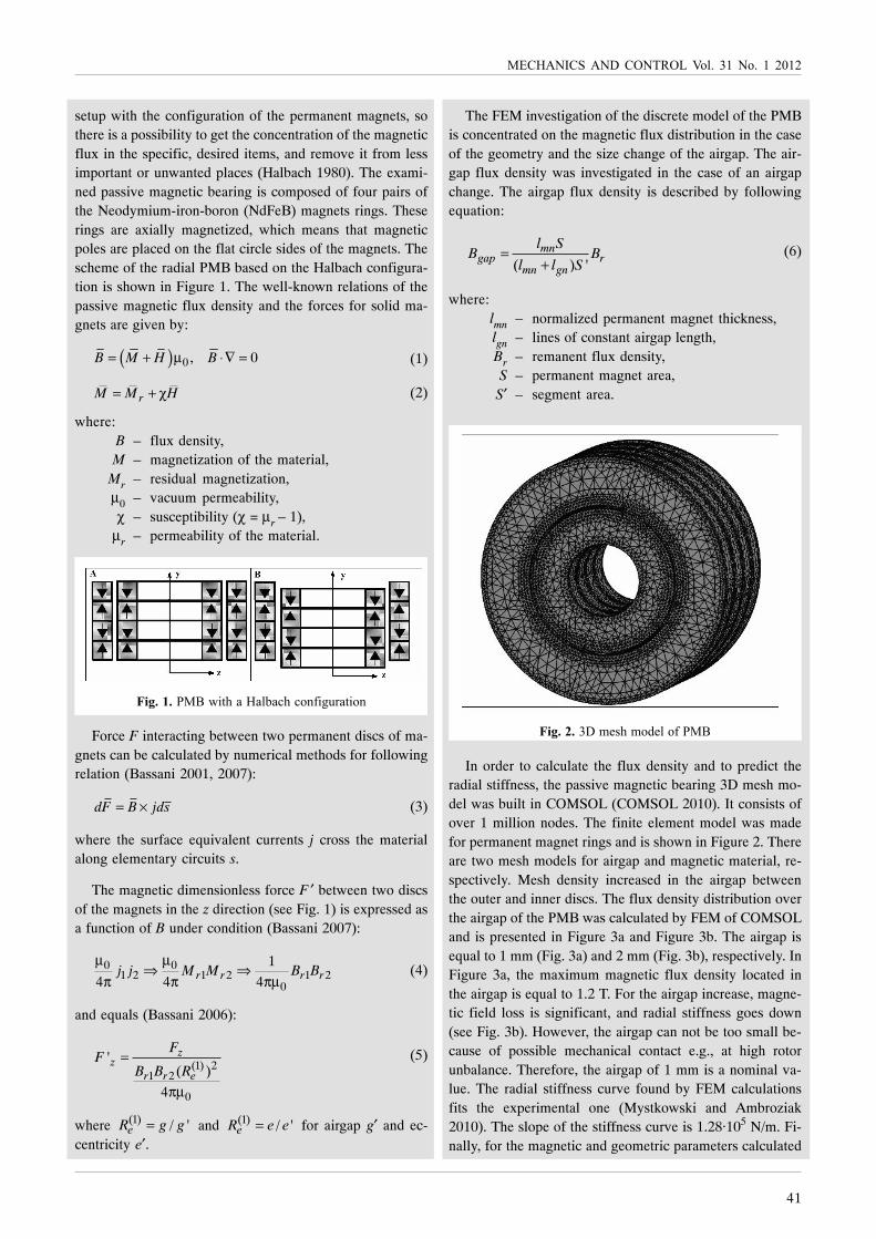
setup with the configuration of the permanent magnets, sothere is a possibility to get the concentration of the magneticflux in the specific, desired items, and remove it from lessimportant or unwanted places (Halbach 1980). The exami-ned passive magnetic bearing is composed of four pairs ofthe Neodymium-iron-boron (NdFeB) magnets rings. Theserings are axially magnetized, which means that magneticpoles are placed on the flat circle sides of the magnets. Thescheme of the radial PMB based on the Halbach configura-tion is shown in Figure 1. The well-known relations of thepassive magnetic flux density and the forces for solid ma-gnets are given by:
( ) 0 , 0B M H B= + μ ⋅∇ = (1)
rM M H= + χ (2)
where:B – flux density,M – magnetization of the material,
Mr – residual magnetization,μ0 – vacuum permeability,χ – susceptibility (χ = μr – 1),
μr – permeability of the material.
�������� ���3�'+�����&6�%+�%),*�-���'�),
Force F interacting between two permanent discs of ma-gnets can be calculated by numerical methods for followingrelation (Bassani 2001, 2007):
dF B jds= × (3)
where the surface equivalent currents j cross the materialalong elementary circuits s.
The magnetic dimensionless force F ′ between two discsof the magnets in the z direction (see Fig. 1) is expressed asa function of B under condition (Bassani 2007):
0 01 2 1 2 1 2
0
1
4 4 4r r r rj j M M B Bμ μ
⇒ ⇒π π πμ
(4)
and equals (Bassani 2006):
(1) 21 2
0
'( )
4
zz
r r e
FF
B B R=
πμ
(5)
where (1) / 'eR g g= and (1) / 'eR e e= for airgap g′ and ec-centricity e′.
The FEM investigation of the discrete model of the PMBis concentrated on the magnetic flux distribution in the caseof the geometry and the size change of the airgap. The air-gap flux density was investigated in the case of an airgapchange. The airgap flux density is described by followingequation:
( ) 'mn
gap rmn gn
l SB B
l l S=
+(6)
where:lmn – normalized permanent magnet thickness,lgn – lines of constant airgap length,Br – remanent flux density,S – permanent magnet area,
S′ – segment area.
����� ��7��2�+�2)��&�)*� ��
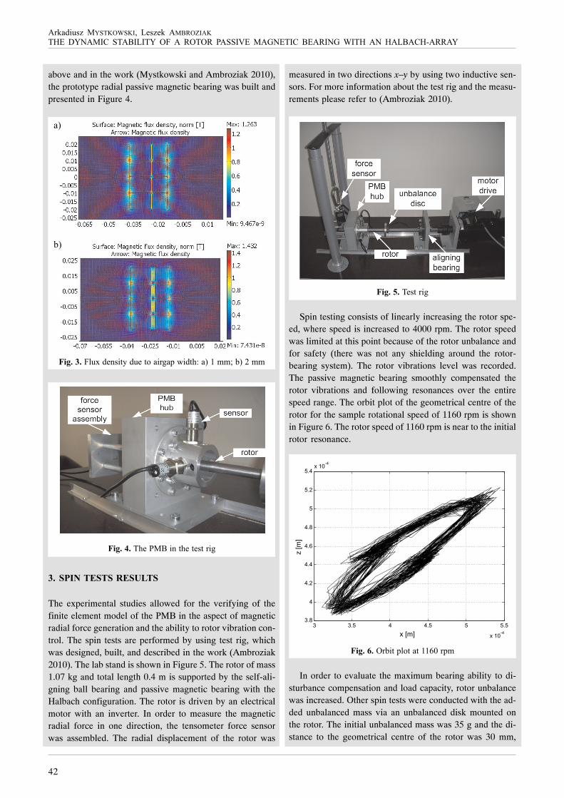
In order to calculate the flux density and to predict theradial stiffness, the passive magnetic bearing 3D mesh mo-del was built in COMSOL (COMSOL 2010). It consists ofover 1 million nodes. The finite element model was madefor permanent magnet rings and is shown in Figure 2. Thereare two mesh models for airgap and magnetic material, re-spectively. Mesh density increased in the airgap betweenthe outer and inner discs. The flux density distribution overthe airgap of the PMB was calculated by FEM of COMSOLand is presented in Figure 3a and Figure 3b. The airgap isequal to 1 mm (Fig. 3a) and 2 mm (Fig. 3b), respectively. InFigure 3a, the maximum magnetic flux density located inthe airgap is equal to 1.2 T. For the airgap increase, magne-tic field loss is significant, and radial stiffness goes down(see Fig. 3b). However, the airgap can not be too small be-cause of possible mechanical contact e.g., at high rotorunbalance. Therefore, the airgap of 1 mm is a nominal va-lue. The radial stiffness curve found by FEM calculationsfits the experimental one (Mystkowski and Ambroziak2010). The slope of the stiffness curve is 1.28·105 N/m. Fi-nally, for the magnetic and geometric parameters calculated
42
�������� � ���������� ����� ���������
���� � ������ �������� � ��� �� ������ ����!����"������ ������"������ ��� �������#����
above and in the work (Mystkowski and Ambroziak 2010),the prototype radial passive magnetic bearing was built andpresented in Figure 4.
���������&�=���,�'(�����')����-�5�3��'+;��A�8�220�6A�9�22
���������+�� ����,�'+��'�'���-
�� ������������������
The experimental studies allowed for the verifying of thefinite element model of the PMB in the aspect of magneticradial force generation and the ability to rotor vibration con-trol. The spin tests are performed by using test rig, whichwas designed, built, and described in the work (Ambroziak2010). The lab stand is shown in Figure 5. The rotor of mass1.07 kg and total length 0.4 m is supported by the self-ali-gning ball bearing and passive magnetic bearing with theHalbach configuration. The rotor is driven by an electricalmotor with an inverter. In order to measure the magneticradial force in one direction, the tensometer force sensorwas assembled. The radial displacement of the rotor was
measured in two directions x–y by using two inductive sen-sors. For more information about the test rig and the measu-rements please refer to (Ambroziak 2010).
����������'���-
Spin testing consists of linearly increasing the rotor spe-ed, where speed is increased to 4000 rpm. The rotor speedwas limited at this point because of the rotor unbalance andfor safety (there was not any shielding around the rotor-bearing system). The rotor vibrations level was recorded.The passive magnetic bearing smoothly compensated therotor vibrations and following resonances over the entirespeed range. The orbit plot of the geometrical centre of therotor for the sample rotational speed of 1160 rpm is shownin Figure 6. The rotor speed of 1160 rpm is near to the initialrotor resonance.
����������6�'�5&)'��'�88B:��52
In order to evaluate the maximum bearing ability to di-sturbance compensation and load capacity, rotor unbalancewas increased. Other spin tests were conducted with the ad-ded unbalanced mass via an unbalanced disk mounted onthe rotor. The initial unbalanced mass was 35 g and the di-stance to the geometrical centre of the rotor was 30 mm,
6A
�A

43
����������������������!)&1� 78� �)1� 8� 9:89
next the unbalanced mass value was increased to 70 g. Thecorresponding orbit plot is presented in Figure 7. The maxi-2�&� �25&�'���� C5���� �)')�� �,6�&�,%�� �D��&� 8EF� )*� �)')�
2��� 6�'� '+�� �)')�� /�6��'�),� #')#5���A� �)�� ,)'� �=%���
:18?�22��3+�%+�2��,� >F�of the airgap. When the rotorspeed was increased to 4000 rpm, peak-to-peak amplitudeequalled to 0.16 mm (Ambroziak 2010).
����������6�'�5&)'��'�88B:��52�3�'+��='����,6�&�,%��
2��)*�>:�-
�� ��������
Based on the design and calculations, permanent magnettypes of magnetic bearings were built and tested due to vi-bration control at a prepared rotor suspension lab rig. Thespin tests were conducted to 4000 rpm, and the rotor vibra-tes in a stable mode. Passive bearing load capacity dependson the arrangement/configuration, the energy density of themagnetic material and the geometry of the solid magnets.However, the implementation of the passive magnetic be-aring requires a careful analysis of the magnetic field gene-rated by permanent magnets, and assesses their materialaspects. The introduction of the Halbach-arrays allows us toorient the magnetic field adequately, and to reduce the nega-tive impact of the active component forces. Finally, theexperimental results show the effectiveness of the passive
bearing system in minimizing radial instability and rotor vi-brations with limited unbalance force.
���� �!"�#
�26�)�����1�9:8:�����A��������� ���������� �����������������������'��� '+������%�&'(�)*���%+�,�%�&��,-1�����&(')��.,�/���'(�)*
��%+,)&)-(�C�,� )&�+A1
���,���1�9::8���������������������������������������!����,�1����61��%�)#��%�)����&/����551�E?>GEE?1
���,���1��9::B��,�����'��"��BCDEFBCCC���������������������6��&���������%%�,�%��?8��551�7>EG7H@1
���,���1� 9::>��7!����� ������!� ��� ������������������������),#&�,�����(,���)�E:��551�8B8G8BH1
������� /��1� 717� 9::B�� �2G72� ��� ��� ������ �����!�� .��� -��������������1
���,+�3��1�8H?9��.�������� ����������� �����������'����� ������������� �������� ������� ����������������26���-�� +�&)1��)%1��>�551�@>G8891
�+2�,,��1�����&�**��1���)��2�,,��1�9::?��2�� ������������������������������'������'�� �� ��������������������� �)%1�)*�'+����,'+�,'��,�'�),�&� �(25)��2� ),� ��-,�'�%� �����,-�� ��=�,-'),�� � �
.������-1
���2���(�I1�1�8@HH������������������� ������������������������!����'��8���& �'����(��������������� ��������������� �����,� �)%18'� �,'��,�'1� �(251� ),���-,�'�%� �����,-�� ��������%+�� �5��,-��#
#!��&�-��551�9EG791
��&6�%+��1�8@H:��7�������� ���������� �� ������������'�������������������������������������%&1��,'�1���'+1��/)&1�8B@��551�8G8:1
��&�,��1�1���&&����� 1�1���)+��1���)�')����1�1�8@@B����������������������������� ���� �'������� � ����������I)��,�&�)*����6)&)-(�
/)&1�88H���)1�?��551�H7@GH?B1
�('�)3��� �1�� �26�)���� �1� 9:8:�� #����������� ��� ������ ��������������'��%�����&����!���%'����%+�,�%���'���')2�'�%���/)&1�?�
�)�?1
�+�3������)����1����')+��1�9:::���� �!��������� ������! ������������������� >'+� �,'1��(25)��2�),���-,�'�%������,-� C����A������%+�
551�7H@G7@?����-�'�9:::1
����2�,,� �1�� ���'��� 1�� ��2�&&�� �1�� "�255� �1� 9:::�� 7����� �������� �����! �� ��� �� HD� =*� ����������� ������������� � �� � ���I�5�,���5��&��551�7>>G7H91
����2�,,��1������1�9:::��HD�=*������������������������� � ����������������>'+��,'1��(25)��2�),���-,�'�%������,-�C����A������%+�
��-�'��551�8H@G8@?1
��')+��1���)����1���+�3���1�9:::���� �!������ ����&�! ������������������� ������ � $� #���� ��� ��� ,��������� ,��������� ��� 5� ���#,,5����,'��,�'�),�&� )3����&�%'�),�%��),*���,%��C� ��A���)�()�I�5�,���5��&�7G>��551�7H@G7@?1
��&),��1���'����� 1�1�8@H8��6���������������������� E'+� �,'1��)��#
+)5�),���������'+G�)6�&'� ��2�,�,'���-,�'� �,�� '+�����55&�%�#
'�),���)�,)����!���>G8:�I�,��8@H81
���+���1���)�����1���),���1�9:::�������������&��&��������8���� �'�����&�����������������������!���I& �����! ������������������,� �)%1�,'��,�'1� )3����&�%'�),�%��),*���,%��� �����)�()1