a pore-scale hydro-mechanical coupled model for …
TRANSCRIPT

II International Conference on Particle-based Methods - Fundamentals and ApplicationsPARTICLES 2011
E. Onate and D.R.J. Owen (Eds)
A PORE-SCALE HYDRO-MECHANICAL COUPLEDMODEL FOR GEOMATERIALS
E. CATALANO∗, B. CHAREYRE∗, A. CORTIS† AND E. BARTHELEMY ††
∗Grenoble INP, UJF Grenoble I, CNRS UMR 5521, 3SR labBP53, 38041 Grenoble Cedex 9, France
e-mail: [email protected]: www.3s-r.hmg.inpg.fr/3sr/
†Earth Sciences DivisionLawrence Berkeley National Laboratory
Berkeley, CA, 94806, U.S.A.
††Grenoble INP, UMR CNRS 5519, LEGIBP 53, 38041 Grenoble Cedex 9, France
Key words: DEM, Fluid-solid coupling, Pore network, Consolidation
Abstract. We present a model for fluid-saturated granular media coupled flow andmechanical deformation. The fluid is assumed to be incompressible and the solid part isassumed to be a cohesive granular material. Forces exerted by the fluid in motion aredeterminated and applied to solid particles. We derive a finite volumes formulation of theflow problem and we couple it to a discrete element method (DEM) formulation of thesolid deformation.
The ability of the algorithm to solve transient problems is tested by simulating anoedometer test on a soil sample. The numerical solution of our model is in good agreementwith Terzaghi’s analytical solution.
1 INTRODUCTION
Discrete element modelling is a tool to study the phenomena that take place at the scaleof elementary components of materials. Such a technique is of great interest when appliedto geomechanics problems. Modelling the hydro-mechanical coupled response of saturatedporous media is indeed one of the main topics of rock and soil mechanics, and inspiredone of the main contributions of Karl Von Terzaghi, whose theory of consolidation of soils“[..]has been one of the strongest incentives in the creation of a science of soil mechanics.(M.A.Biot)”. The model presented in this work aims at providing an effective tool for theanalysis of the mutual influence between internal flow and deformation in geomaterials,
1

E. Catalano, B. Chareyre, A. Cortis and E. Barthelemy
by modelling the interactions that take place at the particles scale. Depending on thetype of problem, various strategies can be adopted for coupling the solid-fluid interaction,which differ essentially on how the fluid phase is being modelled.
At the microscopic (sub-pore) scale, the solid and fluid phases occupy different portionof the spatial domain and interact at their common interface. Thus, the microscopic fieldswhich describe the properties of costituents may be considered as continua within a singlephase, while exhibit discontinuities at the interfaces between phases. At such scale, fluidflow is governed by Stokes equations, which express fluid mass and moment conservationat small Reynolds and Stokes numbers
Op = µO2u− ρOΦ (1)
O · u = 0 (2)
where u, and p are the microscopic fluid velocity and piezometric pressure, respectively,µ is the fluid dynamic viscosity, and Φ is a potential field (e.g., gravitational field). Thepiezometric pressure p is related to the absolute pressure p∗ via p = p∗ − ρΦ. A no-slip boundary condition for the fluid velocity at the grain boundaries is specified, u = 0,which is essentially responsible for the microscopic viscous energy losses (drag) that trans-late in a net loss of the macroscopic piezometric pressure, p, over the length of a porouscolumn. The numerical solution of Stokes equations in spheres assemblies is computation-ally expensive, especially for complex three-dimensional pore geometries. Finite ElementMethods (FEMs) [13] or Lattice-Boltzmann (LB) [14] methods follow a microscopical ap-proach but often find limitations (on the problem size, i.e.) linked to a heavy demand interms of computer memory and computational cost.
The continuum approach is often adopted at the macroscopic level when modellingthe fluid phase in order to get acceptable computational costs [8]. In such approach,there is no direct coupling at the local scale, and flow-induced forces on particles aredefined as function of meso-scale averaged fluid velocity obtained from porosity-basedestimations of the permeability. The use of phenomenological laws for the estimation of thepermeability, however, limits severely the predictive power of these models, in conditionswhere parameter are poorly calibrated. Moreover the adoption of such approach doesnot allow the analysis of the individual particle behaviour, and so cannot be appliedto problems whose nature is purely micromechanical, like strain localization or internalerosion.
The model we propose represents a middle way between the abovementioned ap-proaches: the solid phase is characterized by a sphere packing DEM model, while thefluid phase moves through finite volumes in a pore network built upon a discretization ofthe spheres packing void space, referred hereafter as “Pore scale Finite Volumes’ (PFV).
Pore network models are based on a simplified representation of porous media as anetwork of pore and throats. They have been primarly developed to predict permeabilityof materials [11],[9] or in modelling multiphase flow effects from microstructure geometry[10], [15], [6], provided an appropriate interpretation on how fluids are exchanged between
2

E. Catalano, B. Chareyre, A. Cortis and E. Barthelemy
pores and how such fluxes interact with the solid grains. These aspects will be developedand discussed in what follows. The ability of the model to reproduce the consolidationprocess will be finally tested.
2 THE GRAINS
The Discrete Element Method (DEM), as it is implemented in the open-source codeYADE [19], was used to model the mechanics of the solid phase. The approach is fullymicromechanical, the soil behaviour being modelled by defining the mechanical propertiesof the interaction between the grains [5]. Here, the soil grain’s shape is assumed to bespherical. This is a quiet usual assumption in DEM works, except in cases when thespecific influence of the grain shape on the soil behaviour is under investigation. In othercircumstances, use of polydisperse sphere packings is sufficient to reliably reproduce thesoil behaviour [16].
At each DEM simulation time step, particles in contact are detected and then subjectedto a repulsive force according to an elasto-plastic interaction law. The particles are thenaccelerated according to the second Newton’s law of motion, and their position is updatedfor the next step. A detailed description of YADE DEM implementation in YADE isavailable in the code’s documentation [20].
3 THE PORES
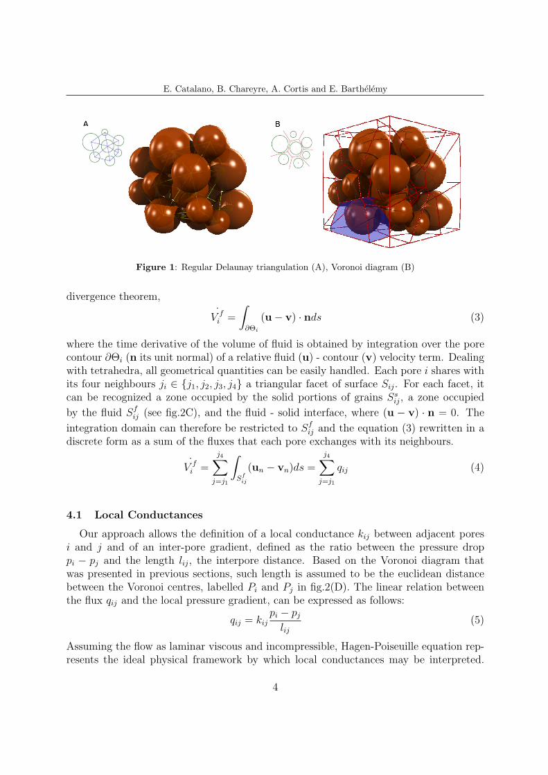
Delaunay triangulation and its dual Voronoi graph were used to discretize the voidspace and formulate the flow problem. Such geometrical representations are commonlyused in soil mechanics for the definition of microscale stresses and strains [12] or in pore-scale modelling of single-phase or multi-phase flow [10]. The C++ library CGAL [17]is used for the triangulation procedure. Here, the generalization to weighted points ofthe Delaunay triangulation (Regular Delaunay triangulation) was adopted, where weightsaccount for the radius of spheres [17]. A system of tetrahedra arises in a 3D framework,each one representing a pore (see fig.1(A) and fig.2). Such scheme constitutes a discretiza-tion of the void space in finite volumes, which will allow the approximation of the flowequations. The dual Voronoi diagram constitutes a network whose edges never cross non-void regions (see fig.1(B)) and form closed regions each one containing exactly one grain(coloured in fig.1(B)). Such network ideally represents the flow path of fluid within theporous sample and allows the formulation and resolution of the flow problem, as it willbe detailed in the following.
4 FLUXES
The porous medium is assumed to be saturated with an incompressible fluid. Foreach tetrahedron of the triangulation, the volume of fluid coincides with the total volumeΘi (see fig.2) which is not occupied by any portion of the spheres. As a consequence,the continuity equation for pore i, can be recast into a surface integral form using the
3
E. Catalano, B. Chareyre, A. Cortis and E. Barthelemy
Figure 1: Regular Delaunay triangulation (A), Voronoi diagram (B)
divergence theorem,
˙V fi =
∫∂Θi
(u− v) · nds (3)
where the time derivative of the volume of fluid is obtained by integration over the porecontour ∂Θi (n its unit normal) of a relative fluid (u) - contour (v) velocity term. Dealingwith tetrahedra, all geometrical quantities can be easily handled. Each pore i shares withits four neighbours ji ∈ {j1, j2, j3, j4} a triangular facet of surface Sij. For each facet, itcan be recognized a zone occupied by the solid portions of grains Ss
ij, a zone occupied
by the fluid Sfij (see fig.2C), and the fluid - solid interface, where (u − v) · n = 0. The
integration domain can therefore be restricted to Sfij and the equation (3) rewritten in a
discrete form as a sum of the fluxes that each pore exchanges with its neighbours.
˙V fi =
j4∑j=j1
∫Sfij
(un − vn)ds =
j4∑j=j1
qij (4)
4.1 Local Conductances
Our approach allows the definition of a local conductance kij between adjacent poresi and j and of an inter-pore gradient, defined as the ratio between the pressure droppi − pj and the length lij, the interpore distance. Based on the Voronoi diagram thatwas presented in previous sections, such length is assumed to be the euclidean distancebetween the Voronoi centres, labelled Pi and Pj in fig.2(D). The linear relation betweenthe flux qij and the local pressure gradient, can be expressed as follows:
qij = kijpi − pjlij
(5)
Assuming the flow as laminar viscous and incompressible, Hagen-Poiseuille equation rep-resents the ideal physical framework by which local conductances may be interpreted.
4

E. Catalano, B. Chareyre, A. Cortis and E. Barthelemy
Figure 2: Volume of fluid in a pore (A), adjacent pores and local connections (B), fluid domain of porecontour (C), pore partition for hydraulic radius definition (D)
Considerable efforts have been devoted in the literature to the generalization of Poiseuille’slaw to pores of complex shape [7], and to the definition of a ngeneralized hydraulic radius[3]. By analogy with the Hagen-Poiseuille relation, kij may therefore be defined as follows:
kij = αSfijR
hij2
µ(6)
where α is a non-dimensional conductance factor which reflects the throat’s shape. Forα = 1/2, Hagen-Poiseuille equation takes the classical form which can be obtained forcircular shaped conduits. µ is the fluid dynamic viscosity. Sf
ij is the fluid domain of
equation (4). The hydraulic radius Rhij is defined as the ratio between a volume filled
with liquid and a wetted surface,
Rhij =
V olumefluidSurfacewetted
=Θij
γij(7)
for each pore connection, ij. As already seen in previous sections, neighbouring poreshave three grains in common, and thus three vertices of the triangulation resulting in atriangular plane facet. Those three vertices, together with the Voronoi centres (Pi, Pj, seefig.2(D)) that are defined for the two pores, define a relevant pore partitioning and allowto access the total fluid volume Θij and the wetted surface γij, and the correspondinghydraulic radius (see fig.2(D)).
4.2 Forces
We will give very few details on the definition of forces exerted by the fluid to thesolid particles. For a complete description on how the expressions that will be presentedhereafter have been obtained, refer to Chareyre et al. [1].
The total force F k on particle k can be defined as follows:
5

E. Catalano, B. Chareyre, A. Cortis and E. Barthelemy
Figure 3: Coupled DEM-Flow computation cycle
F k =
∫∂Γk
(p∗n+ τn)ds (8)
where ∂Γk denotes the solid surface of the particle k, p∗ the absolute pressure and τ theshear stress. As detailed in the introduction, the piezometric pressure p governing theflow problem is defined as p = p∗− ρΦ(x). By this definition, the F k term can be splittedin three components:
F k =
∫∂Γk
ρΦ(x)nds+
∫∂Γk
pnds+
∫∂Γk
τnds = F b,k + F p,k + F v,k (9)
where F b,k denotes the buoyancy force, that can be computed indipendently, while F p,k
and F v,k are those forces which result from viscous flow, respectively due to losses ofpiezometric pressure and to viscous shear stress.
5 PROBLEM SOLUTION
The resolution of the flow problem can now be integrated into the algorithm presentedin section 2. Combining equations (4) and (5), we obtain:
˙V fi =
j4∑j=j1
qij = kijpi − pjlij
= Kij(pi − pj) (10)
At each cycle of computation, once the positions of the spheres are updated, new contactsare detected and the volumetric variation of pores is computed. The contact law andthe fluid problem resolution give the contact forces and the fluid forces to be applied toparticles, whose positions is again updated according to the law of motion (see fig.3). Thematrix Kij is sparse, symmetric and positive defined. The linear system is then solved byusing an over-relaxed Gauss-Seidel algorithm.
6

E. Catalano, B. Chareyre, A. Cortis and E. Barthelemy
Figure 4: Predicted permeabilities. Comparison with experimental/analytical/numerical results (a).Pressure field (b).
6 PERMEABILITY MEASUREMENTS
The first tests that have been prepared to verify the relevance of the model implemen-
tation were based on the analysis of a flow trough a fixed solid skeleton (˙V fi = 0 in eq.10).
A pressure gradient was then applied to the granular sample. The flow boundary condi-tions are the ones shown in fig. 5: pressure is imposed on top and bottom boundaries,while a no-flux condition is imposed on lateral boundaries. Thus, on top and bottomboundaries the pressure was imposed and fixed (p = 1 and p = 0 respectively). Inlet Qi
and outlet Qo flow rates can be then measured. It was found that Qi − Qo < 106 ' 0,which indicates a good convergence of the numerical solver. An estimation of a macro-scopic Darcy-like permeability [m2] of the sample is then possible, being possible to assessthe Darcy velocity of fluid flowing within the sample, VDarcy = Q/S, with S the sectionof the sample and Q = Qi = Qo. Permeability can be thus estimated from the followingrelation:
K = µQ
S
h0
∆p[m2] (11)
where h0 is the height of the sample, ∆p the pressure drop and µ the viscosity of the fluid.Figure 4(a) compares the assessed permeability values with experimental data by Willieand Gregory [18], the Ergun equation and numerical results obtained by Thompson [11].Figure 4(b) shows the pressure field associated to the given boundary conditions.
Table 1 shows a comparison between the PFV solution with the solution obtained bysmall scale Stokes flow FEM computations in terms of degrees of freedom to computethe pressure field and CPU time for solving. It can be seen how in the case of PFVcalculation, the total number of DOFs and CPU time required for calculating flow andforces acting on the particles are reduced drastically with respect to small scale Stokes flowFEM calculations. Not available values are relative to computations whose occupancy of
7

E. Catalano, B. Chareyre, A. Cortis and E. Barthelemy
memory was out the computer’s capacity. The pressure fields and effective permeabilitiesthat were computed had been compared to FEM solutions and found in good agreement.For details, see Chareyre et al.[1].
Table 1: Comparison of DOF’s and CPU time between FEM and PFV (one iteration).
Nb of spheres FEM dof’s PFV dof’s FEM time [s] PFV time [s]9 1.7e5 45 300 0.00022200 1.2e6 1093 5400 0.00462e3 not available (n.a.) 12e3 n.a. 0.0912e4 n.a. 11e4 n.a. 2.21
7 MONODIMENSIONAL CONSOLIDATION
The ability of the algorithm to solve transient problems was finally tested by analyzingthe consolidation process of a sample subjected to axial load. Grains are free to move, sothe system to be solved is the one expressed in eq.(10). Boundary conditions are set inorder to reproduce an oedometer test, as it will be detailed hereafter. The analysis of theevolution of settlement and excess pore pressure in space and time and the comparisonof the numerical solution with the analytical solution obtained by Terzaghi in 1923 in his“Theory of consolidation of soils” will constitute a validation for the model.
7.1 The Terzaghi’s analytical solution
The consolidation process is a classical hydro-mechanical problem. The mechanismsthat govern the evolution of the deformation depend on a variation of effective stresses,coupled to processes of diffusion of the interstitial water. Such phenomenon dependstherefore on the properties of the porous medium, like permeability and deformability, andon the problem geometry, defined by the boundary conditions and the drainage patternswhich characterize the medium. The load applicated to a saturated medium is initiallyentirely carried by the fluid phase, as the water can not instantly flow out of the medium.An increase of pore pressure is induced, whose entity varies within the medium, whilethe external pressure keep a costant value u0. A gradient of pressure is then established,resulting in a filtration flux whose duration depend on the medium properties. As thewater progressively flows out of the medium, the load is transferred from to liquid to thesolid phase, and the medium starts to deform. The process ends once the excess porewater pressure is fully dissipated.
The equation of monodimensional consolidation reads:
∂u
∂t= Cv
∂2u
∂z2(12)
8

E. Catalano, B. Chareyre, A. Cortis and E. Barthelemy
where u is the fluid pressure, z the height of the sample, Cv the consolidation coefficient,defined as follows:
Cv =K
mvgρw(13)
where K is the permeability of the soil expressed in m/s, mv = ∆εv/∆σ′v the coefficient
of volume compressibility, g the gravity acceleration and ρw the density of the fluid.Terzaghi’s analytical solution is usually given in terms of consolidation degree Uz, definedas the ratio between the excess pore pressure at instant t and the initial one, and averagedegree of consolidation Um, defined for a soil layer of heigth H as the ratio between thesettlement S at the instant t, (S(t) = ∆H(t)), and the final settlement Sc (Sc = ∆Hfinal).
Uz =u(z, t)
umax
(14)
Um =S(t)
Sc
(15)
A non-dimensional time parameter is introduced, Tv, defined as:
Tv =Cvt
L2(16)
where t is the effective time, and L the longest drainage path of the generic fluid particle.Tv = 0 at the begin of consolidation, whereas Tv = 1 (100%) at the end of the process.
7.2 Numerical results
Setting up the simulation, boundary conditions were defined according to the oedo-metric conditions, which mirror the main hypothesis of Terzaghi’s theory, briefly recalledhereafter: settlements and fluxes take place along one unique direction; the soil is ho-mogenous and saturated; stress-strain relation is linear; the liquid and solid phase areincompressible; small and time-independent strains; validity of Darcy’s Law. Boundaryconditions are shown in figure 5. Lateral strains are imposed to be none (εxx = εyy = 0).A slip condition was set at the boundaries. Both upward and downward drainage wayswere activated (L = H/2 in eq.16). A relative dense sample was created, to minimize thedispersion of pores’ dimension and avoid strong heterogeneities within the sample. 5000slightly polydispersed grains were employed to build a cubic sample (l = 0.1m) which wasthen subjected to an axial external load σext = 5kPa. The external fluid pressure was setto be none, u0 = 0.
The result that were obtained are shown in figure 6, with the evolution ef excesspore pressure (left diagram) which rose up to 5kPa (= σext = umax) and then graduallydecreased. A good agreement is found in terms of evolution of settlement and excess ofpore pressure. The central diagram shows the evolution of Uz, as defined in eq.14. Thefour curves are relative to four phases of the consolidation process, for Tv = 0.0 (0%
9

E. Catalano, B. Chareyre, A. Cortis and E. Barthelemy
Figure 5: Boundary Conditions (left). Pressure field (10% of consolidation completed) (right).
Figure 6: Oedometric Consolidation - Results obtained and comparison with Terzaghi solution
of consolidation completed), Tv = 0.25, Tv = 0.50, Tv = 0.75. The analytical solution(continued line) is compared to the numerical result (points) and found in good agreement.Similarly, the right curve shows the evolution of settlements.
8 CONCLUSIONS
We presented a pore-scale hydromechanical model for geomaterials that allows for areliable and computationall efficient of the force exchange between fluid phase and solidparticles, modeled a sphere packing. The pore-network model proved to be a relevantapproach to interprete the physical phenomena that take place at the microscopic scale.The adoption of spherical grains assures an easy-to-handle pore geometry, and simplifiesthe derivation of local conductivities and fluid forces.
Comparison with small-scale Stokes flow FEM calculation shows how the CPU timerequired for solving the flow problem is drastically reduced by 6 orders of magnitude inour PFV-DEM approach. A good agreement has been found both in terms of pressurefield and estimation of effective permeability. The ability of our approach to solve tran-
10

E. Catalano, B. Chareyre, A. Cortis and E. Barthelemy
sient problems was tested by analyzing the consolidation process of a saturated samplesubjected to axial load. The solution obtained is in good agreement with Terzaghi’sanalytical solution (both in time and space).
The application of the model to problems concerning internal erosion [2] and sedimenttransport in rivers are being tested. Current works focus on the reproduction of theliquefaction phenomenon as it takes place within a seabed under the action of naturalocean waves.
REFERENCES
[1] B. Chareyre, A. Cortis, E. Catalano, E. Barthelemy. Pore-scale Modeling of ViscousFlow and Induced Forces in Dense Sphere Packings. (submitted) (2011)
[2] H. Sari, B. Chareyre, E. Catalano, P. Philippe, E. Vincens. Investigation of internalerosion processes using a coupled DEM-Fluid method. Particles 2011 II InternationalConference on Particle-Based Methods, E. Oate and D.R.J. Owen (Eds), Barcelona(2011)
[3] Happel J., Brenner H. Low Reynolds Number Hydrodynamics. Martinuis NijhoffPublishers, Dordrecht (1986)
[4] M.A. Biot. General theory of three dimensional consolidation. Journal of AppliedPhysics (1941) 12:155–164.
[5] P.A. Cundall and O.D.L. Strack. A discrete numerical model for granular assemblies.Geotechnique (1979) 29:47–65.
[6] R. R. O. Bonilla. Numerical simulation of undrained granular media. PhD Thesis,University of Waterloo (2004)
[7] Hilpert M.,Glantz R. and Miller C.T. Calibration of a Pore-Network Model by aPore-Morphological Analysis. Transport in Porous Media (2003) 51:267–285.
[8] M Zeghal and U El Shamy. A continuum-discrete hydromechanical analysis of gran-ular deposit liquefaction Int. J. Numer. Anal. Meth. Geomech. (2004) 14:(28)1361–1383.
[9] Bryant S. and Blunt M. Prediction of relative permeability in simple porous media.Phys. Rev. A (1992) 4:(46)2004–2011.
[10] Steven Bryant and Anna Johnson. Wetting phase connectivity and irreducible sat-uration in simple granular media. Journal of Colloid and Interface Science (2003)2:(263)572–579.
[11] K. E. Thompson and H. S. Fogler. Modeling flow in disordered packed beds frompore-scale fluid mechanics. AIChE Journal (1997) 6:(15)1377–1389.
11

E. Catalano, B. Chareyre, A. Cortis and E. Barthelemy
[12] Katalin Bagi. Analysis of microstructural strain tensors for granular assemblies In-ternational Journal of Solids and Structures (2006) 43:(10)3166–3184.
[13] R. Glowinski and T. W. Pan and T. I. Hesla and D. D. Joseph and J. Periaux. AFictious Domain Approach to the Direct Numerical Simulation of IncompressibleViscous Flow past Moving Rigid Bodies: Application to Particulate Flow. Journalof Computational Physics (2001) 2:(169)363–426.
[14] Han K., Feng Y.T., Owen D.R.J.Coupled Lattice-Boltzmann and discrete elementmodelling of fluid-particle interaction problems. Computer and Structures (2007)85:1080–1088
[15] Nordhaug H.F., Celia M., Dahle H.K. A pore network model for calculation of inter-facial velocities. Advances in Water Resources (2003) 26:1061–1074.
[16] Chareyre B., Modelisation du comportement d’ouvrages composites sol-geosynthetique par element discrets - Application aux ancrages en tranchees en tetede talus. PhD Thesis, Universite de Grenoble I - Joseph Fourier (2003)
[17] Boissonnat J.D., Devillers O., Pion S., Teillaud M. and Yvinec M., Triangulations inCGAL Computational Geometry: Theory and Applications (2002) 22:5–19
[18] Wyllie M.R.J., Gregory A.R., Fluid Flow trough Unconsolidated Porous AggregatesIndustrial and Engineering Chemistry (1995) 47:(7)1379-1388
[19] Smilauer V. and Chareyre B., Yade Dem Formulation. Yade Documenta-tion (V. Smilauer, ed.), The Yade Project, 1st ed. (2010) (http://yade-dem.org/doc/formulation.html)
[20] V. Smilauer, E. Catalano, B. Chareyre, S. Dorofeenko, J. Duriez, A. Gladky, J. Koz-icki, C. Modenese, L. Scholtes, L. Sibille, J. Stransky, and K. Thoeni. Yade ReferenceDocumentation. Yade Documentation (V. Smilauer, ed.), The Yade Project, 1st ed.(2010) (http://yade-dem.org/doc/.)
12