a practical approach in the cfd simulation of off-shore
TRANSCRIPT
A practical approach in the CFD simulation of off-shore wind farms
through the actuator disc technique
F. Castellani, A. Gravdahl, G. Crasto, E. Piccioni, A. Vignaroli
Presenter: Dr. Giorgio Crasto, WindSim AS Contact author: Prof. Francesco Castellani, University of Perugia
Trondheim, 24-25 January 2013

THE WindSim MODEL Key features • WindSim (WS) is commercial software package for wind flow
simulations based on Computational Fluid Dynamics (CFD)
• WS provides a user-friendly interface for the CFD core PHOENICS (by CHAM)
• The code solves automatically the Reynolds Average Navier Stokes (RANS) equations (steady solution) on different direction sectors
Very easy to setup a simulation on a real terrain case
Easy grid control
Quite fast solution
Strictly Cartesian orthogonal grid
Solution with RANS and quite standard turbulence models

Using an orthogonal Cartesian grid WS is designed to operate on rectangular domains. This introduce different boundary layers conditions between orthogonal and skewed direction sectors.
Orthogonal flows: 1 inlet 1 outlet 2 frictionless walls
Skewed flows: 2 inlet 2 outlet
Vertical distribution
The Grid
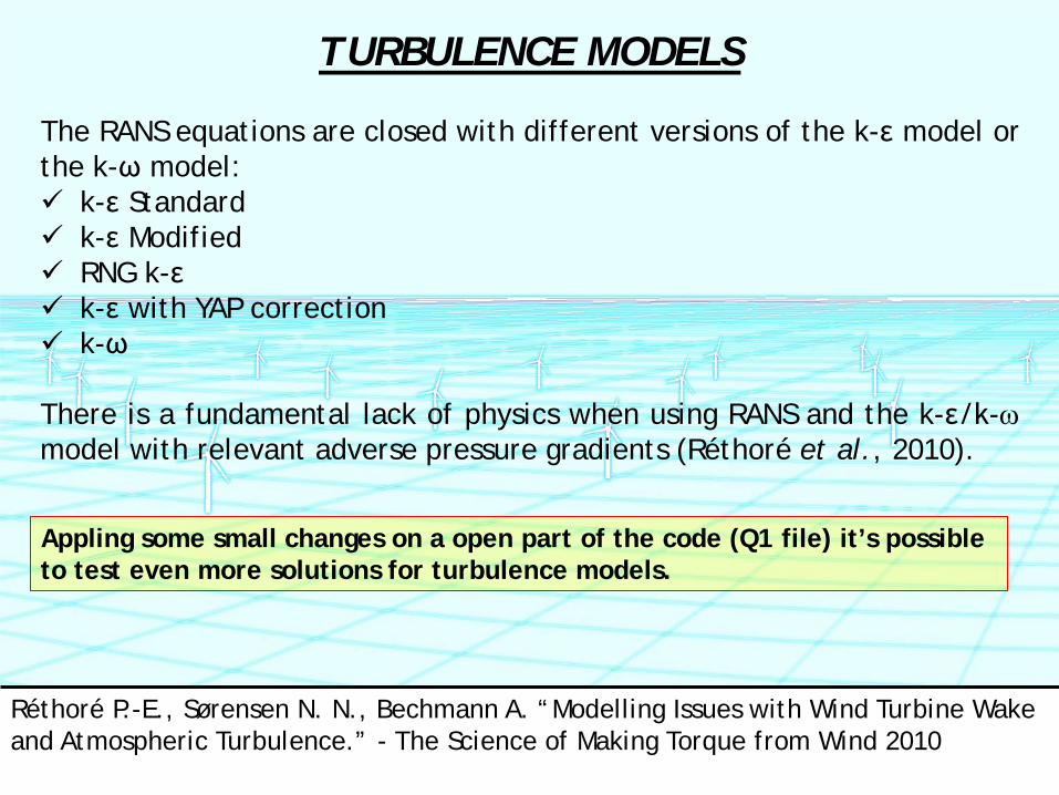
The RANS equations are closed with different versions of the k-ε model or the k-ω model: k-ε Standard k-ε Modified RNG k-ε k-ε with YAP correction k-ω There is a fundamental lack of physics when using RANS and the k-ε/k-ω model with relevant adverse pressure gradients (Réthoré et al., 2010).
Appling some small changes on a open part of the code (Q1 file) it’s possible to test even more solutions for turbulence models.
Réthoré P.-E., Sørensen N. N., Bechmann A. “Modelling Issues with Wind Turbine Wake and Atmospheric Turbulence.” - The Science of Making Torque from Wind 2010
TURBULENCE MODELS

WAKES MODELLING
WindSim provides two different ways to consider wakes in the numerical solution: 1. Using analytical models in the post-processing of the CFD/RANS
calculations a. Jensen model (momentum deficit theory) b. Larsen model (turbulent boundary layer equations) c. Model with a turbulent depending rate of wake expansion
2. Use the actuator disc (AD) model within the CFD/RANS calculations Only axial forces are applied on the disc All rotational effects are disregarded The thrust is applied according to the
thrust coefficient curve of the wind turbine using the actual speed calculated on the rotor (correction with axial induction).
USE OF THE TESTBATTERIES
• The test battery is a numerical tool designed to be used during the development of each new version of the code.
• With the test battery it is possible to run the model in a batch/silent mode, changing the calculation parameters automatically and check all monitored outputs.
• The test battery can be very useful also for research purpose. A good part of the development of the test battery was carried-out at the WindSim headquarter in Norway by Emanuele Piccioni, a PhD student from the University of Perugia during his four-months stage within the Erasmus Placement project.

TESTING A NEW SOLVER WITH THE TESTBATTERIES
Adjusting the convergence criteria for the new GCV, a SIMPLE-C solver acting on a collocated,
BFC grid.

TESTING A NEW SOLVER WITH THE TESTBATTERIES
Assessing the performance on complex-terrain
Coupled solver with staggered grid GCV solver with collocated grid
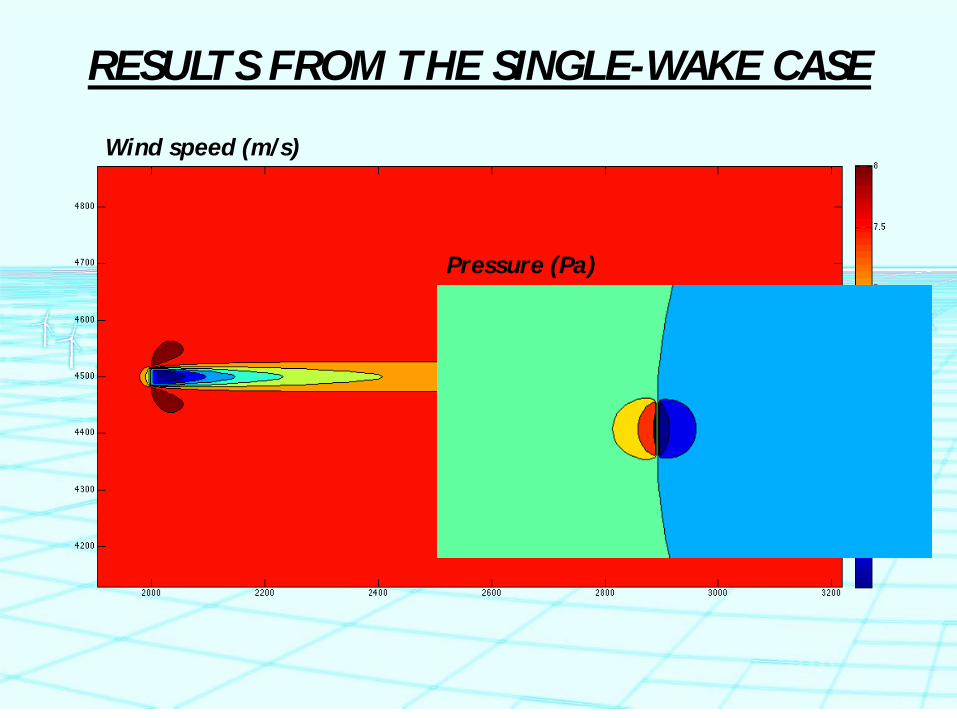
RESULTS FROM THE SINGLE-WAKE CASE
m/s
Wind speed (m/s)
Pressure (Pa)

RESULTS FROM THE SINGLE-WAKE CASE Using the testbattery to reach the upstream wind speed conditions:
Velocity upstream (m/s)

RESULTS FOR THE DOUBLE WAKE CASE
m/s

DEALING WITH SKEWED FLOWS
SINGLE WAKE CASE
ROTOR
Due to the flow symmetry it is possible to move the sensor rather than changing the wind direction.

DEALING WITH SKEWED FLOWS
DOUBLE WAKE CASE
In this case it is necessary to rotate the layout (and the sensor positions). If the terrain is not flat also the rotation of the DTM is needed. This is the only possibility to have the rotors exactly facing the wind.

CALCULATING THE REYNOLDS STRESS TENSOR COMPONENTS
The eddy viscosity was estimated according to the chosen turbulence model (RNG k-ε) in order to solve the equations:
The turbulence is modeled as isotropic; the partial derivate of the wind speed components were evaluated using a discrete approach.
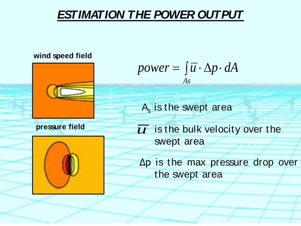
∫ ⋅∆⋅=As
dApupower
u is the bulk velocity over the swept area
Δp is the max pressure drop over the swept area
wind speed field
pressure field
As is the swept area
ESTIMATION THE POWER OUTPUT
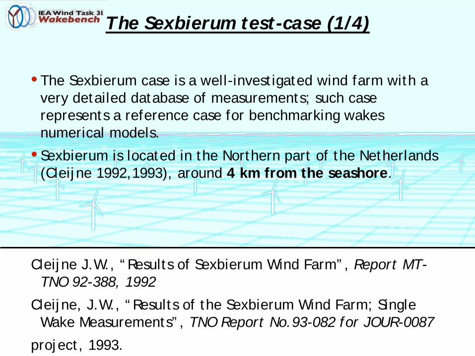
The Sexbierum test-case (1/4)
• The Sexbierum case is a well-investigated wind farm with a very detailed database of measurements; such case represents a reference case for benchmarking wakes numerical models.
• Sexbierum is located in the Northern part of the Netherlands (Cleijne 1992,1993), around 4 km from the seashore.
Cleijne J.W., “Results of Sexbierum Wind Farm”, Report MT-TNO 92-388, 1992
Cleijne, J.W., “Results of the Sexbierum Wind Farm; Single Wake Measurements”, TNO Report No.93-082 for JOUR-0087
project, 1993.
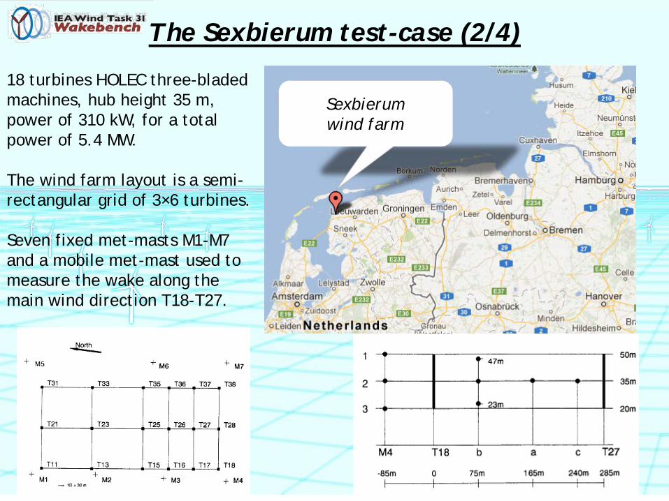
The Sexbierum test-case (2/4)
Sexbierum wind farm
18 turbines HOLEC three-bladed machines, hub height 35 m, power of 310 kW, for a total power of 5.4 MW. The wind farm layout is a semi-rectangular grid of 3×6 turbines. Seven fixed met-masts M1-M7 and a mobile met-mast used to measure the wake along the main wind direction T18-T27.
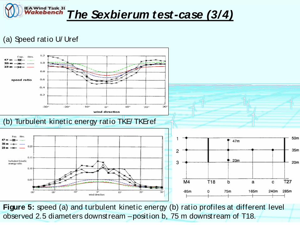
The Sexbierum test-case (3/4)
(a) Speed ratio U/Uref
(b) Turbulent kinetic energy ratio TKE/TKEref
Figure 5: speed (a) and turbulent kinetic energy (b) ratio profiles at different level observed 2.5 diameters downstream – position b, 75 m downstream of T18.
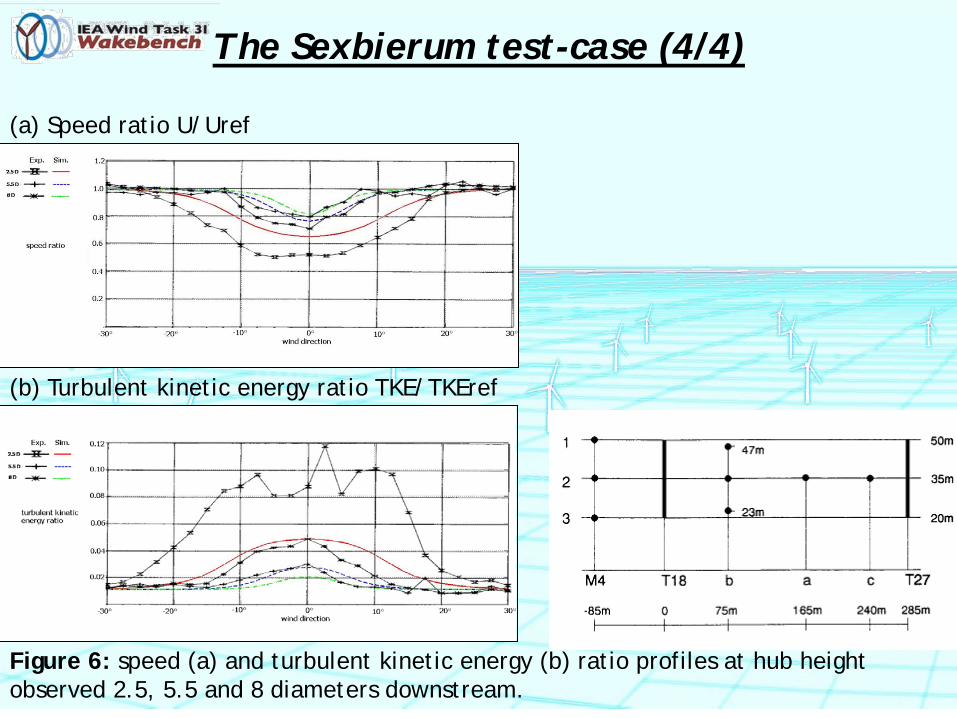
The Sexbierum test-case (4/4)
(a) Speed ratio U/Uref
(b) Turbulent kinetic energy ratio TKE/TKEref
Figure 6: speed (a) and turbulent kinetic energy (b) ratio profiles at hub height observed 2.5, 5.5 and 8 diameters downstream.
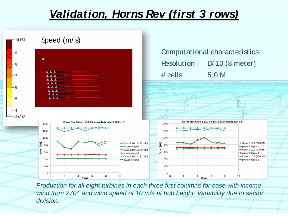
Validation, Horns Rev (first 3 rows)
Production for all eight turbines in each three first columns for case with income wind from 270° and wind speed of 10 m/s at hub height. Variability due to sector division.
Computational characteristics:
Resolution D/10 (8 meter)
# cells 5.0 M
0
200
400
600
800
1000
1200
1400
0 2 4 6 8 10
Pow
er [k
W]
Rows
Horns Rev Case 1.10.1 10 m/s at hub height 270° ± 1°
Case 1.10.1 (270°±1°)power integralCase 1.10.1 (270°±1°)power integralCase 1.10.1 (270°±1°)power integral
0
200
400
600
800
1000
1200
1400
0 2 4 6 8 10
Pow
er [k
W]
Rows
Horns Rev Case 1.10.2 10 m/s at hub height 270° ± 5°
Case 1.10.2 (270°±5°)power integral 1Case 1.10.2 (270°±5°)power integral 1Case 1.10.2 (270°±5°)power integral 1
Speed (m/s)
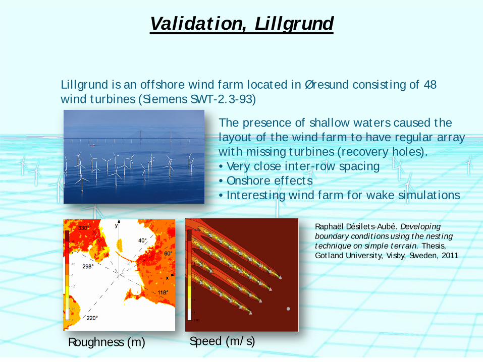
Validation, Lillgrund
Lillgrund is an offshore wind farm located in Øresund consisting of 48 wind turbines (Siemens SWT-2.3-93)
The presence of shallow waters caused the layout of the wind farm to have regular array with missing turbines (recovery holes). • Very close inter-row spacing • Onshore effects • Interesting wind farm for wake simulations
Raphaël Désilets-Aubé. Developing boundary conditions using the nesting technique on simple terrain. Thesis, Gotland University, Visby, Sweden, 2011
Roughness (m) Speed (m/s)
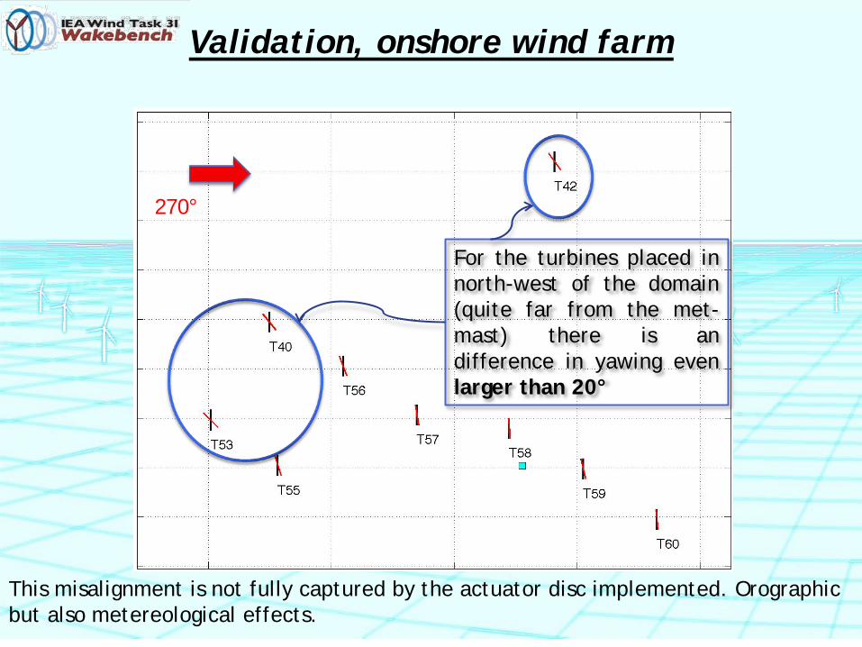
Validation, onshore wind farm
270°
For the turbines placed in north-west of the domain (quite far from the met-mast) there is an difference in yawing even larger than 20°
This misalignment is not fully captured by the actuator disc implemented. Orographic but also metereological effects.
Conclusions
1. WindSim with the Actuator disc model can be a useful tool for simulation of wakes on real cases (offshore and onshore);
2. Using RANS and the k-ε turbulence model can introduce some critical issue for the model not realizable (near wake);
3. Another critical part of the model can be connected with the lack of swirl in the wake (near wake);
4. Comparison with SCADA data is possible but a large uncertainty can be introduced by rotors yaw misalignments (this issue is more critical in onshore wind farms).

FUTURE WORK 1. ON THE MODEL SIDE
a. Complete the simulations with different wind speed conditions using the testbattery
b. Improving turbulence modeling (realizable models?) c. Define the best force distribution on the rotor d. Introduce thermal stratification e. Introduce swirl of wake
2. ON THE EXPERIMENTAL SIDE
a. Understand misalignments (for onshore application) b. Introduce much more information on the actual wind
direction c. Analyze seasonal behaviors

THANK YOU FOR YOUR ATTENTION
If you want to know more about this tool … Dr. Giorgio Crasto, WindSim AS (NO) [email protected]
Prof. Francesco Castellani, University of Perugia (IT) [email protected]