a practical guide to iec 62353 - rigel medicala practical guide to iec ΩΩµμµ pg 5 ∙ the...
TRANSCRIPT

A Practical Guide to IEC 62353
rigelmedical.com

RIGEL MEDICAL
PG 2 TESTED, TRUSTED… WORLDWIDE.
© Copyright 2019 - All rights reserved. Nothing from this edition may be multiplied, or made public in any form or manner, either electronically, mechanically, by photocopying, recording, or in any manner, without prior written consent from Seaward Electronic Ltd. This also applies to accompanying drawings and diagrams.
CONTENTS
03 Foreword
04 Introduction
07 Medical electronic equipment
11 IEC 60601
12 Introduction to IEC 62353: 2014
15 Visual inspection
15 Earth bond testing
18 Insulation resistance test
22 IEC 62353 leakage measurements
33 Record keeping
34 Conclusion
36 Appendix A: Pass/fail limits of IEC 62353
37 Appendix B: IEC 60601-1 collateral standards
38 Appendix C: IEC 60601 test standards
43 Appendix D: Patient environment
44 Appendix E: Example documentation
45 Products in the Rigel Medical range
46 Accessories and services from Rigel Medical
A PRACTICAL GUIDE TO IEC 62353
PG 3
43 Appendix D: Patient environment
44 Appendix E: Example documentation
45 Products in the Rigel Medical range
46 Accessories and services from Rigel Medical
Rigel Medical: Keeping medical industries safeWorld-leading biomedical test and measurement equipment
At Rigel Medical, we’ve been a pioneer of biomedical test and measurement instruments for more than four decades.
Since launching the world’s first IEC 601 electrical safety analyser in the 1970s, our user focused developments continue to place us at the forefront of the industry.
Our comprehensive suite of electrical safety analysers, performance analysers and vital signs simulators enable biomedical and clinical engineers to confirm their adherence to a series of industry standards, manufacturers’ specifications and most importantly, keeping patients, visitors, and staff safe in a healthcare environment.
Alongside our commitment to quality, we also offer peace of mind to our customers who know that help and advice is always available.
Foreword This booklet is written as a guideline for people involved in testing medical electrical (ME) equipment.
This booklet cannot be considered as a replacement for the IEC 62353 publication, which can be purchased through the official IEC website, http://webstore.iec.ch/.
All reasonable care has been taken to ensure the accuracy of the information, reference figures and data has been taken from the latest versions of various standards, guidance notes and recognised ‘best practices’ to establish the recommended testing requirements however, Rigel Medical, their agents and distributors, accept no responsibility for any error or omissions within this booklet, or for any misinterpretations by the user.
For clarification on any part of this booklet please contact Rigel Medical before operating any test instrument, under relevant legislation.
No part of this publication shall be deemed to form, or be part of any contract for training or equipment unless specifically referred to as an inclusion within such contract.
Rigel Medical assumes that the readers of this booklet are electronically technically competent and therefore, does not accept any liability arising from accidents or fatalities resulting directly or indirectly from the tests described in this booklet.
Author John Backes, MA
RIGEL MEDICAL
PG 4 TESTED, TRUSTED… WORLDWIDE.
IntroductionThis guide covers a basic introduction to electrical safety, definitions of a medical electronic device, the IEC 60601 standard and an in depth overview of the IEC 62353 publication.
The structure and topics discussed in this guide are written in a way such that the widest possible audience can benefit.
Electrical currentElectrical current is a secondary energy form consisting of the flow of charge (in coulomb) through a circuit over a certain time period, and is depicted in ampere.
I = Q/t or 1 Ampere = 1 Coulomb/1 second
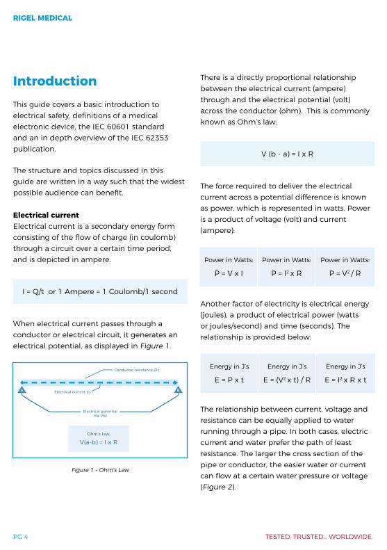
When electrical current passes through a conductor or electrical circuit, it generates an electrical potential, as displayed in Figure 1.
There is a directly proportional relationship between the electrical current (ampere) through and the electrical potential (volt) across the conductor (ohm). This is commonly known as Ohm’s law:
V (b - a) = I x R
The force required to deliver the electrical current across a potential difference is known as power, which is represented in watts. Power is a product of voltage (volt) and current (ampere):
Another factor of electricity is electrical energy (joules), a product of electrical power (watts or joules/second) and time (seconds). The relationship is provided below:
The relationship between current, voltage and resistance can be equally applied to water running through a pipe. In both cases, electric current and water prefer the path of least resistance. The larger the cross section of the pipe or conductor, the easier water or current can flow at a certain water pressure or voltage (Figure 2).
Conductor resistance (R)
Electrical current (I)
Electrical potential (Va-Vb)
Ohm’s law;
V(a-b) = I x R
A B
Ohm’s law;
V(a-b) = I x R
Figure 1 - Ohm’s Law
Power in Watts:
P = V x I
Power in Watts:
P = I2 x R
Power in Watts:
P = V2 / R
Energy in J’s
E = P x t
Energy in J’s
E = (V2 x t) / R
Energy in J’s
E = I2 x R x t

A PRACTICAL GUIDE TO IEC 62353
PG 5
∙ The thinner or longer the water pipe, the more water pressure is required to deliver the same litres per minute (flow or current)
∙ The thinner or longer the conductor (assuming a particular specific resistance of material), the more voltage is required to deliver the same current.
The human bodyA significant part of the human body is made up of water along with dissolved ions and minerals, which are capable of conducting electrical currents. Broadly speaking, the hazard of such electrical currents would depend on:
∙ Strength of the current ∙ Path of the current ∙ Total impedance for the current path ∙ Frequency of the current ∙ Duration of the current being applied
Electrical currents can be extremely dangerous to the human body. The energy released by electrical current passing through human tissue can generate burns and excite or stimulate muscles of the respiratory system (intercostal).
The most critical muscles are those in the human heart, which are driven (excited) by very tiny amounts of electrical currents. When the heart is exposed to external electrical currents (electrical shock), the heart can lose its normal sinus rhythm, required to sustain a healthy
Power in Watts:
P = V x I
Power in Watts:
P = I2 x R
Power in Watts:
P = V2 / R
Energy in J’s
E = P x t
Energy in J’s
E = (V2 x t) / R
Energy in J’s
E = I2 x R x t
Figure 2 - Example showing water following path of least resistance
Water Electricity
Current or flow Litre/second Current Ampere (coulomb second)
Pressure e.g. bar or psi Voltage Volt
Resistance Affected by pipe cross section and length
Resistance In ohm (Ω). Affected by conductor cross section, length and material

RIGEL MEDICAL
PG 6 TESTED, TRUSTED… WORLDWIDE.
blood circulation, and move into ventricular fibrillation. This stops the circulation of oxyhaemoglobin (oxygenated blood) to the brain and organs and when left untreated, will result in death within 15 minutes.
Ironically, the most common treatment of ventricular fibrillation is the use of a defibrillator which delivers a very high current pulse, up to 100A across the heart. The energy in that high current pulse is sufficient to temporarily clamp the heart muscles (i.e. stop the heart completely) before releasing it again and allowing the heart to resume its normal sinus rhythm.
Consider the following examples of a macro shock showing the effect of a 50/60 Hz current on the human body when applied to the skin for 1–3 seconds non-invasively:
0.5 -1.1 mA Current just noticeable when applied to the fingertip.
6 – 16 mA Painful shock, unable to let go, cannot be tolerated over 15 minutes.
75-400 mA Ventricular fibrillation, respiratory arrest, leading to death.
<1 A Serious burns and muscular contraction of such a degree that the thoracic muscles constrict the heart.
Figure 3 highlights the different effects of electrical current on the human body as understood by Dr. Howard M. Hochberg;
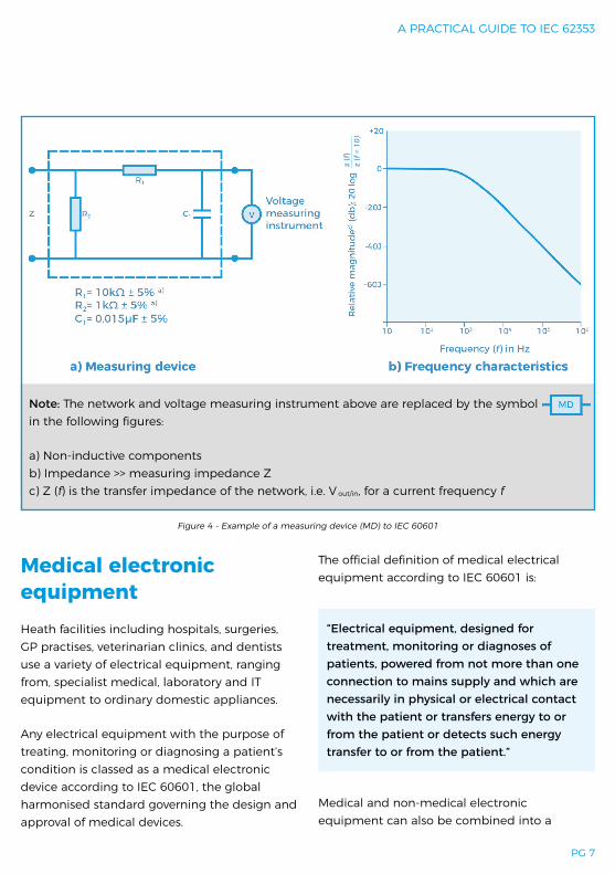
IEC 60601 body modelTo ensure a standardised method of simulating the impedance of the human body, measurement circuits have been designed to simulate the average, typical electrical characteristics of the human body. These measurement circuits are referred to as a body model or measuring device (MD in IEC 60601-1).
The main impedance is formed by a 1kΩ resistor, shown in Figure 4.
Figure 3 - Impact of current on the human body, adapted from research by Howard M. Hochberg, 1971
(Data adapted from published research by Professor C.F. Dalziel)
A PRACTICAL GUIDE TO IEC 62353
PG 7
Medical electronic equipment Heath facilities including hospitals, surgeries, GP practises, veterinarian clinics, and dentists use a variety of electrical equipment, ranging from, specialist medical, laboratory and IT equipment to ordinary domestic appliances.
Any electrical equipment with the purpose of treating, monitoring or diagnosing a patient’s condition is classed as a medical electronic device according to IEC 60601, the global harmonised standard governing the design and approval of medical devices.
The official definition of medical electrical equipment according to IEC 60601 is:
“Electrical equipment, designed for treatment, monitoring or diagnoses of patients, powered from not more than one connection to mains supply and which are necessarily in physical or electrical contact with the patient or transfers energy to or from the patient or detects such energy transfer to or from the patient.”
Medical and non-medical electronic equipment can also be combined into a
Figure 4 - Example of a measuring device (MD) to IEC 60601
z (f)
z (f
= 10
)
Note: The network and voltage measuring instrument above are replaced by the symbol in the following figures:
a) Non-inductive componentsb) Impedance >> measuring impedance Zc) Z (f) is the transfer impedance of the network, i.e. V out/in, for a current frequency f
f
RIGEL MEDICAL
PG 8 TESTED, TRUSTED… WORLDWIDE.
medical electronic system. To ensure safety of patient and operator, this system must meet the design requirements of IEC 60601.
The definition of a medical electronic system is:
“Combination of equipment of which at least one is classed as medical electrical equipment and as such specified by the manufacturer to be connected by functional connection or use of a multiple portable socket-outlet.”
Commonly used terms and definitions in IEC 62353Equipment under test - The equipment (EUT) which is the subject of testing.
Device under test (DUT) - The device which is the subject of testing.
Applied part - Part of the medical equipment, which is designed to come into physical contact with the patient, or parts that are likely to be brought into contact with the patient.
Patient connection - Individual physical connections and/or metal parts intended for connection with the patient, which form (part of) an applied part.
Patient environment - Volumetric area in which a patient can come into contact with medical equipment or contact can occur between other persons touching medical equipment and the patient, both intentional and unintentional. (see Appendix D).
F-Type applied part - Applied part which is electrically isolated from earth and other parts of the medical equipment, i.e. floating. F-Type applied parts are either type BF or type CF applied parts.
Type B applied part - Applied part complying with specified requirements for protection against electric shock. Type B applied parts are those parts, which are usually earth referenced. Type B are those parts not suitable for direct cardiac application.
Type BF applied part - F-Type applied part complying with a higher degree of protection against electric shock than type B applied parts. Type BF applied parts are those parts not suitable for direct cardiac application.
Type CF applied part - F-Type applied part complying with the highest degree of protection against electric shock. Type CF applied parts are those parts suitable for direct cardiac application.
Class I - Equipment protection against electric shock by (earthed) additional protection to basic insulation through means of connecting exposed conductive parts to the protective earth in the fixed wiring of the installation.
Class II - Also referred to as double insulated. Equipment protection against electric shock is achieved by additional protection to basic insulation through means of supplementary insulation, there being no provision for the connection of exposed metalwork of the equipment to a protective conductor and no reliance upon precautions to be taken in the fixed wiring of the installation.

A PRACTICAL GUIDE TO IEC 62353
PG 9
Protective earth - Dedicated circuit intended to carry the fault and leakage current in Class I equipment and to be connected to the protective earth terminal.
Functional earth - Dedicated circuit intended to provide an electrical screening and to be connected to a functional earth terminal.
Line to earth voltage - Applied voltage between the live wire and earth conductor, affecting the leakage current.
Leakage current - Current that is not functional.
Macroshock - Non-invasive applied current which passes from one side of the body to the other, typically hand to hand or hand to foot, and therefore crossing through the heart.
Microshock - Invasively applied current which passes directly across the heart tissue.
Note: Class II equipment may be provided with a functional earth terminal or a functional earth conductor.
Symbols and markingsThe IEC 60601 defines the requirements for information/data to be present on the medical equipment’s nameplate, in order to form an unambiguous identification of the equipment.
Information must include; manufacturers name, model number, serial number, electrical requirements.
The IEC 60601 standard refers to a large variety of symbols for use on medical equipment,
medical systems, accessories and other related parts. A full overview of the symbols used in IEC 60601 is provided in table D1 of the standard.
For the purpose of this booklet, a selection of the most commonly used symbols is displayed below:
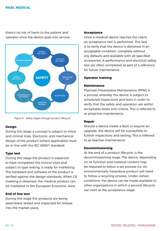
Product lifecycleFor many years, ME equipment has been subject to extensive approval processes from clinical trials, to type testing all the way through to end of production line testing, to ensure it operates properly before leaving the factory. In addition, manufacturers recommend that regular electrical safety and essential performance checks are carried out to ensure
Protective Earth
Earth reference point
Functional Earth Class II
i.e. “Conformité Européenne”
Type B applied part
Defibrillation-proof type B applied part
Type BF applied part
Defibrillation-proof type BF applied part
Type CF applied part
Defibrillation-proof type CF applied part
RIGEL MEDICAL
PG 10 TESTED, TRUSTED… WORLDWIDE.
there’s no risk of harm to the patient and operator once the device goes into service.
DesignDuring this stage a concept is subject to initial and clinical trials. Electronic and mechanical design of the product (where applicable) must be in line with the IEC 60601 standard.
Type testDuring this stage the product is expected to have completed the clinical trials and, subject to type testing, is ready for marketing. The hardware and software of the product is verified against the design standards. When CE marking is obtained, the medical product can be marketed in the European Economic Area.
End of line testDuring this stage the products are being assembled, tested and inspected for release into the market place.
AcceptanceOnce a medical device reaches the client, an acceptance test is performed. This test is to verify that the device is delivered in an acceptable condition, complete without any defaults and available with all specified accessories. A performance and electrical safety test are often completed as part of a reference for future maintenance.
Operator training
MaintenancePlanned Preventative Maintenance (PPM) is a process whereby the device is subject to scheduled inspections and tests in order to verify that the safety and operation are within acceptable levels and criteria. This is referred to as proactive maintenance.
RepairShould a device create a fault or require an upgrade, the device will be susceptible to further inspections and testing. This is referred to as reactive maintenance.
DecommissioningAt the end of a product lifecycle, is the decommissioning stage. The device, depending on its function and material content may be required to follow a set process (i.e. An environmentally hazardous product will need to follow a recycling process. Under certain conditions, the device can be made available to other organisations in which a second lifecycle can start at the acceptance stage.
SAFETY
DESIGN(IEC 60601)
TYPE TEST(IEC 60601)
END OF LINETEST
ACCEPTANCE
OPERATORTRAINING
MAINTENANCE(IEC 62353)
REPAIR(IEC 62353)
DECOMMISSIONING
Figure 5 - Safety stages through product lifecycle
A PRACTICAL GUIDE TO IEC 62353
PG 11
IEC 60601ME equipment must meet the design requirements as set out by the IEC 60601 (a harmonised standard), which has been adopted by all IEC member states. This sets out all the design criteria for producing equipment that is electrically and mechanically safe, as well as placing the onus on the manufacturer to understand how to reduce the risk of harm when patient and operators are exposed to their medical devices. All tests relating to the electrical safety of ME equipment and devices can be categorised into two categories:
∙ Means of operator protection (MOOP) - Means of protection for reducing the risk of electric shock to persons other than the patient
∙ Means of patient protection (MOPP) - Means of protection for reducing the risk of electric shock to the patient
To ensure that ME equipment does not pose an electrical hazard to the patient, or any other person, it is designed with sufficient levels of isolation (dielectrics) to reduce the amount of electrical leakage current to an acceptable and safe level - as low as 10µA . This is achieved by separating high electrical potentials from any conductive parts, accessible to the operator or patient. Dielectric strength is proven by applying a high voltage between high and low electrical potentials. However, this could lead to a breakdown of the isolation and would therefore be referred to as a destructive test.
A safer way to test the effectiveness of dielectrics is to perform a number of electrical leakage tests, such as leakage originating from
the power supply to the enclosure (MOOP) or protective earth wire (MOOP and MOPP) or even to the patient connected parts (MOPP).
In IEC 60601, the test requirements for electrical leakage must be carried out under the worst possible conditions to ensure maximum safety. This is achieved using an elevated mains at 110% of the highest expected voltage (i.e. at 240V mains this would mean testing at 264V) and also by preconditioning the ME equipment prior to testing, before performing tests under normal condition (no fault conditions), and including any one of the specific and relevant fault conditions.
Testing the protective earth circuit design for sufficient current carrying capabilities is achieved by stressing the design, passing a minimum test current of 25 ampere RMS through the circuit for a minimum of 10 seconds. At these current levels, time duration and resistance values (<0.1 Ohm internal equipment resistance), enough energy will be created to convert current into thermal heat. By observing the thermal profile of a design, one can establish parts of the design that might need to alter in order to reduce the electrical resistance and therefore the converted energy is:
E = I2 x R x t
Conducting such tests during the development and approval stages of a product life cycle provides sufficient levels of confidence that the ME equipment meets the design requirements of IEC 60601. Once a design is approved for
RIGEL MEDICAL
PG 12 TESTED, TRUSTED… WORLDWIDE.
manufacturing and marketing, a subset of tests will suffice to ensure the product has been built and assembled to the required product quality and safety requirements. This subset of tests is commonly referred to as routine tests and are not clearly defined in IEC 60601, and can therefore vary between manufacturers and product designs. It’s for this reason that the IEC 62353:2014 makes a recommendation that IEC 62353 is used during final testing and before putting a piece of ME equipment into service.
In-service test requirementsIEC 60601-1 does not provide any guidance on routine test requirements. This has led to different interpretations on how to apply IEC 60601 to routine test scenarios.
Once a medical device leaves the factory, a number of potential test scenarios arise, including:
Acceptance testing also referred to as an initial or reference test. This test is carried out prior to a new medical device being authorised for use and is undertaken to ensure correct and complete delivery. Acceptance testing is often not limited to an electrical safety test, with some basic function tests also being applied to verify correct performance.
Routine testing also referred to as planned preventative maintenance (PPM). This form of testing is often conducted at fixed time intervals, which vary between types of equipment, manufacturers’ recommendations and risk assessment procedures undertaken by individual biomedical/clinical engineering or medical physics departments. Routine testing is not limited to safety testing and often includes the verification of correct functionality.
After service and repair testing this is carried out following a repair or product upgrade and is often part of a service carried out by in-hospital mechanical or clinical engineering teams. In many cases, more rigorous electrical safety testing is needed after the replacement of components or reconfiguration of medical devices.
Introduction to IEC 62353: 2014As its full name implies, IEC 62353 Medical Electrical Equipment - recurrent test and test after repair of ME equipment defines the requirements for electrical safety testing of medical electrical (ME) equipment and systems during routine intervals.
Following the need for a unified approach to routine testing, the first edition of IEC 62353 brought together a set number of tests to allow its users to test the MOOP and MOPP dielectric integrity via two distinct leakage current tests:
∙ Equipment leakage - Testing the total leakage generated from the incoming mains to the rest of the equipment (confirming integrity of the MOOP)
∙ Applied part leakage - Testing that floating applied parts (Type BF and Type CF) remain at an acceptable floating level (confirming integrity of the MOPP)
In meeting this requirement the IEC 62353 incorporates tests beyond those of type testing. Specifically, it seeks to provide a uniformed and unambiguous means of assessing the safety of medical equipment, whilst maintaining the relevance to IEC 60601-1 and minimising the
A PRACTICAL GUIDE TO IEC 62353
PG 13
risks to the person conducting the assessment.
Importantly, the IEC 62353 standard recognises that the laboratory conditions described in the IEC 60601, such as elevated mains, isolated TN (terre neutral) supply, temperature and humidity conditions cannot always be guaranteed when in-service testing of medical devices is undertaken. More commonly, secondary earth connections caused by data cables and systems, provided measurement errors that can now be overcome by IEC 62353. Another factor raised is that equipment could potentially be damaged by applying type test specifications (IEC 60601) when in service and could therefore represent a potential danger to users.
One of the most significant changes to the 2014 edition is the recommendation to test according to IEC 62353 at the final production line stage and also before equipment goes into service. This will allow recurrent testing to be directly comparable with factory tests, providing for easier greater observation of any variations in leakage measurement. New in the IEC 62353:2014 edition is a number of suggested leakage tests that would isolate the touch leakage current or patient leakage current. Both tests form part of the equipment leakage current.
However, if a manufacturer wants to provide a specific measurement, the IEC 62353:2014 now provides guidance for these tests to be conducted in the informative section of the standard, which might be considered when the equipment leakage values have changed from previous measurements. The 500V DC insulation tests in the 2014 edition have also been supplied with recommended
pass/fail limits, taken from internationally accepted practices for insulation testing of electrical equipment. While insulation tests are optional, it’s recommended to check with the equipment manufacturer if this can be conducted without damaging the equipment under test.
The strength of IEC 62353 enables those who carry out testing to conduct a summary of tests on the input of medical devices (equipment leakage) and on the output of the medical equipment (applied part leakage). As will become evident from the following chapters, the time saving associated with IEC 62353 will also allow for more time to be spent on visual and functional testing.
How does IEC 62353 compare with IEC 60601?Although IEC 60601 is a type test standard governing the safety of the design and manufacture of ME equipment, for decades biomedical and clinical engineers have used the IEC 60601 as the basis for regular testing or after service/repair of medical devices. Local variants of IEC 60601 have also been adopted and used as a basis for routine testing.
It is clear that most commonly used electrical safety analysers will only provide means of testing to a subset of tests described in IEC 60601 and often exclude destructive tests such as high voltage dielectric testing, constant current 25A testing and SIP/SOP fault condition testing to aid portability and safety of the operator.
So what are the main implications of testing to IEC 62353 and how does it differ from the very well established and widely understood
RIGEL MEDICAL
PG 14 TESTED, TRUSTED… WORLDWIDE.
requirements of IEC 60601?
Test frequencyTo ensure safety and performance is managed throughout the lifecycle of medical electrical equipment, manufacturers must specify the intervals for testing and inspecting their devices. The basis for this is risk assessment: the likelihood of occurrence and severity of incorrect operation. Consideration has to also be given to the application of the product, frequency of use, the operational environment and operator competency. IEC 62353:2014 recommends following the manufacturer’s instructions on test intervals. If this is not available, a test interval between of between 6 and 36 months is suggested depending on risk assessment.
Technical considerationsThe aim of IEC 62353 is to provide a uniform standard that ensures safe practices and reduces the complexity of the current IEC 60601-1 standard. All tests are based on leakage testing to IEC 60601, but a number of aspects to improve safety and practicality have been removed.
The most significant changes are:
∙ No pre-conditioning of equipment under test
∙ No elevated mains ∙ No destructive testing ∙ Testing under single fault condition only ∙ Summarising leakage into input and output
safety ∙ Testing at applied part level rather than at
patient connection - Different methods for conducting leakage
tests subject to practicality
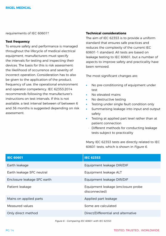
Many IEC 62353 tests are directly related to IEC 60601 tests, which is shown in Figure 6.
IEC 60601 IEC 62353
Earth leakage Equipment leakage DIR/DIF
Earth leakage SFC neutral Equipment leakage ALT
Enclosure leakage SFC earth Equipment leakage DIR/DIF
Patient leakage Equipment leakage (enclosure probe disconnected)
Mains on applied parts Applied part leakage
Measured values Some are calculated
Only direct method Direct/Differential and alternative
Figure 6 - Comparing IEC 60601 with IEC 62353
A PRACTICAL GUIDE TO IEC 62353
PG 15
Vital preparationAlthough IEC 62353 was first published in May 2007, many companies and organisations are still in the process of making changes to their approach to electrical safety testing. To incorporate the IEC 62353 test philosophy into any organisation requires necessary preparation. Options for choosing the correct set of tests requires an understanding of the purpose and benefits of using the different tests available.
Although the onus will inevitably fall on the manufacturers of medical devices to advise on appropriate in-service test procedures for their own equipment, IEC 62353 clearly has an impact on medical service companies, biomedical engineering, medical physics, clinical engineering and other technical departments.
To help all those likely to be affected by the introduction of IEC 62353 tests, a summary of the test requirements is provided within this guidance booklet.
This IEC 62353 guidance booklet is intended for general information only and cannot be considered a substitute for the full version of the standard.
Visual inspectionThe process of visual inspection is not clearly defined by IEC 60601, however visual inspections form a critical part of the general safety inspections during the functional life of medical equipment. In most cases, 70% of all faults are detected during visual an inspection.
A visual inspection is a relatively easy procedure, which is carried out to ensure that the ME equipment in use still conforms to the specifications released by the manufacturer and has not suffered from any external damage and/or contamination.
The following inspections can be included:
∙ Housing/enclosure - look for damage, cracks etc.
∙ Contamination - look for obstruction of moving parts, connector pins etc.
∙ Cabling (supply, applied parts etc.) - look for cuts, wrong connections etc.
∙ Fuse rating - check correct values after replacement
∙ Marking and labelling - check the integrity of safety markings
∙ Integrity of mechanical parts - check for any obstructions
Earth bond testingProtective earth conductors are designed to allow a safe and easy path (low resistance) for electrical leakage and fault currents to flow, which allows the protective fuses or line current monitors (RCDs, GFIs) to operate and interrupt the supply voltage. This provides an important means to reduce the risk of injury by electric shock and also stops the release of energy which may ultimately lead to fires.
In Class I electrical equipment, the protective earth conductor resistance needs to be of sufficiently low value in order to prevent the voltage on external metal parts rising to a level where the shock potential presents a hazard to life.
RIGEL MEDICAL
PG 16 TESTED, TRUSTED… WORLDWIDE.
Although many Class I medical devices are supplied with an earth reference point, most if not all medical devices require multiple earth bond tests to validate the connections of additional metal accessible parts on the enclosure.
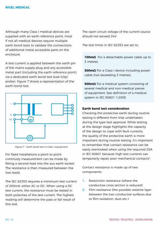
A test current is applied between the earth pin of the mains supply plug and any accessible metal part (including the earth reference point) via a dedicated earth bond test lead (clip/probe). Figure 7 shows a representation of the earth bond test.
For fixed installations a point-to-point continuity measurement can be made by fitting a second lead into the aux earth socket. The resistance is then measured between the two leads.
The IEC 62353 requires a minimum test current of 200mA, either AC or DC. When using a DC test current, the resistance must be tested in both polarities of the test current. The highest reading will determine the pass or fail result of this test.
The open circuit voltage of the current source should not exceed 24V.
The test limits in IEC 62353 are set to:
100mΩ For a detachable power cable up to 3 metres.
300mΩ For a Class I device including power cable (not exceeding 3 metres).
500mΩ For a medical system consisting of several medical and non-medical pieces of equipment. See definition of a medical system in IEC 60601-1:2005.
Earth bond test consideration Checking the protective earth during routine testing is different from that undertaken during the type test approval. While testing at the design stage highlights the capacity of the design to cope with fault currents, the quality of the protective earth is more important during routine testing. It’s important to remember that contact resistance can be easily overlooked when using the required 25A in IEC 60601 because high test currents can temporarily repair poor mechanical contactsiii.
Contact resistance is made up of two components:
1. Restriction resistance (where the conductive cross section is reduced)
2. Film resistance (the possible resistive layer between the two conductive surfaces due to film oxidation, dust etc.)
L
N
PE
Ω
Figure 7 - Earth bond test in Class I equipment

A PRACTICAL GUIDE TO IEC 62353
PG 17
Lower test currents, typically less than 8A RMS, are unable to temporarily overcome contact resistance (both film and restriction resistance) and therefore highlight problems as a result of aging: increased restriction resistance due to softening of spring loaded force on the contacts typically found in removable power cords, as illustrated in Figure 8.
High test currents (10A or more) tend to provide a more constant reading (high precision) even if there is a potential constriction in the protective earth path. High test currents might also be destructive to parts of the DUT which are connected to the protective earth but have a functional purpose (e.g. screening).
Therefore, IEC 62353 recommends that protective earth connections are tested with a 200mA test current to highlight aging power cords, although high readings could be as a result of film resistance which can be removed.
Combining a high pre-pulse (to clean the film resistance) and measuring with a low current to show up any restriction resistance is the most accurate way to determine the quality of
the protective earth path.
Precision vs accuracyWhen performing an earth bond test, remember that accuracy must take precedence over precision as having a consistently wrong measurement is precise but not very accurate.
Using a high test current might provide a higher precision (see Figure 9), but would not necessarily give you a more accurate representation of the quality of the protective earth circuit due to its capability to temporarily repair constriction resistance.
Lower currents are not able to provide a false positive and are therefore fail-safe.
Low test current only (see Figure 9) - Possible low accuracy and low precision as high readings could be due to film or constriction resistance.
High test current only (see Figure 10) - Possible high precision but low accuracy as aging cables with poor contact resistance will give the same readings as a brand new good cable.
Low pressure appliedIncreased pressure
(High resistance) (Low resistance)
Figure 8 - Example of increased contact resistance in spring loaded contacts

RIGEL MEDICAL
PG 18 TESTED, TRUSTED… WORLDWIDE.
Figure 9 - Low accuracy - low precision Figure 10 - Low accuracy - high precision Figure 11 - High accuracy - high precision
Low test current with high current pre-test (see Figure 11) - Cleans film resistance, any high readings would be down to poor contact resistance, therefore high accuracy and high precision.
Insulation resistance testThe risk of unacceptably high electrical fault currents can be minimised through design criteria i.e. through effective levels of electrical insulation/isolation between the operator or patient and live parts or potentially live parts in a fault condition. Such insulation can be achieved through physical spacing (creepage and clearance) of components, choice of components, and dielectric materials in order to achieve the required levels of insulation while ensuring the device operates properly.
The effectiveness of electrical insulation is tested through electrical leakage measurements (results in mA or μA) while the level of isolation is often tested using a dielectric or insulation test. During a dielectric, or hipot test, a potentially high voltage (up to 4000V AC) is applied across different parts
of the electronic design in order to stress the dielectrics. Results are displayed in mA or μA - similar to that of leakage current measurements. An insulation resistance test applies a lower DC voltage, typically between 250-500V DC, across different parts of the electronic design. The results are displayed in megaohms (MΩ).
Insulation resistance is normally checked by applying 500V DC between:
∙ Input (live conductors, both phase and neutral, connected together) and enclosure (protective earth in class 1). (See Insulation resistance: EUT to earth).
∙ Output (applied parts) and enclosure (protective earth in class 1). (See Insulation resistance: applied parts).
A PRACTICAL GUIDE TO IEC 62353
PG 19
∙ Input (phase and neutral) and output (applied parts) for floating type applied parts (BF and CF). (See Insulation resistance: applied parts to mains).
The resistance is measured and then compared with the minimum acceptable value to assess pass or fail conditions, which can vary greatly depending on design and test voltage variations.
With all measurements of insulation resistance, the appliance under test must have the power switch in the “ON” position before performing the test otherwise the test voltage does not pass beyond the mains switch, in which case only the mains in the cord will be tested.
However, since the insulation resistance test does not power up the appliance, which could be seen as an advantage (reducing the time taken to test and eliminating the danger of moving hazardous parts), extra care should be taken to ensure the equipment switch is in the ‘on’ position to complete a meaningful test.
In addition, appliances fitted with electronic mains switches or RCD plugs cannot be tested in this manner because it is not possible to close the mains switch (as they require mains to be present).
In some cases, sensitive electronic devices and particularly older IT equipment, which does not comply with EN60950, may be damaged by 500V. However, in practice, this may not be a significant issue as EN 60950 has been around longer than most IT equipment currently in use.
While the outcome of a 500V DC insulation test is quick and safe to do, in most cases it does
not provide a real indication of the effectiveness of the insulation in modern medical devices or the expected leakage values that may be experienced during normal or typical operation. This is due to the increased use of switch mode power supplies that may indicate very high DC insulation resistance (>100MΩ), when measured with AC indicate high leakage. This is due to the greater influence of capacitive and inductive leakage experienced in these devices rather than resistive leakage as in a heating element.
Infinity readings are common when performing DC insulation tests and provide no information as to whether the unit was actually switched on or off. This makes the test results meaningless from a safety point of view.
It is a matter of debate as to whether a 50 MΩ (higher) result is ‘safer’ than a 10 MΩ (lower) result, considering the equipment has been exposed to a voltage it was not designed to operate at. Furthermore, the 50 MΩ (higher) device might have been designed to measure 100 MΩ and has therefore lost 50% of its insulation level. This could lead to higher leakage currents and unsafe conditions.
Finally, in some electrical equipment, components connected to the live/neutral conductors for EMC filtering or surge protection can significantly influence the measurement, indicating an erroneous failure of the test. On the plus side, the insulation resistance test is relatively quick and easy to perform, which is why it is probably the most widely used.
Insulation resistance test: EUT to earthThis test is used to verify that the mains parts are adequately insulated from earth (Class I)
RIGEL MEDICAL
PG 20 TESTED, TRUSTED… WORLDWIDE.
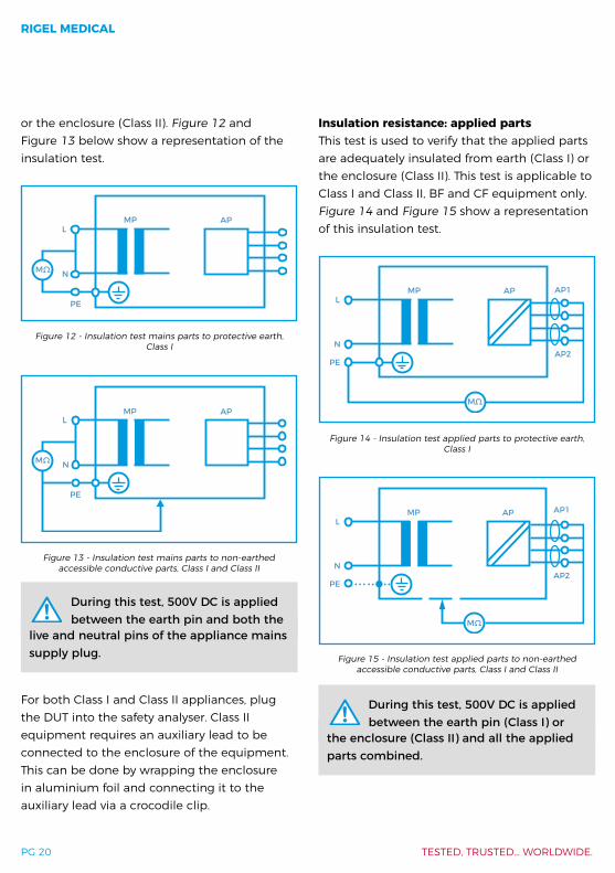
or the enclosure (Class II). Figure 12 and Figure 13 below show a representation of the insulation test.
During this test, 500V DC is applied between the earth pin and both the
live and neutral pins of the appliance mains supply plug.
For both Class I and Class II appliances, plug the DUT into the safety analyser. Class II equipment requires an auxiliary lead to be connected to the enclosure of the equipment. This can be done by wrapping the enclosure in aluminium foil and connecting it to the auxiliary lead via a crocodile clip.
Insulation resistance: applied partsThis test is used to verify that the applied parts are adequately insulated from earth (Class I) or the enclosure (Class II). This test is applicable to Class I and Class II, BF and CF equipment only. Figure 14 and Figure 15 show a representation of this insulation test.
During this test, 500V DC is applied between the earth pin (Class I) or
the enclosure (Class II) and all the applied parts combined.
APMPL
N
PE
MΩ
Figure 12 - Insulation test mains parts to protective earth, Class I
APMPL
N
PE
MΩ
Figure 13 - Insulation test mains parts to non-earthed accessible conductive parts, Class I and Class II
Figure 14 - Insulation test applied parts to protective earth, Class I
AP AP1
AP2
MPL
N
PE
MΩ
AP AP1
AP2
MPL
N
PE
MΩ
Figure 15 - Insulation test applied parts to non-earthed accessible conductive parts, Class I and Class II
A PRACTICAL GUIDE TO IEC 62353
PG 21
For both Class I and Class II appliances, connect the patient connections or applied parts to the corresponding terminals of your safety analyser. For Class I equipment, plug the mains plug into the safety analyser. Class II equipment requires an auxiliary lead to be connected to the enclosure of the equipment. This can be done by wrapping the enclosure in aluminium foil and connecting the auxiliary lead via a crocodile clip.
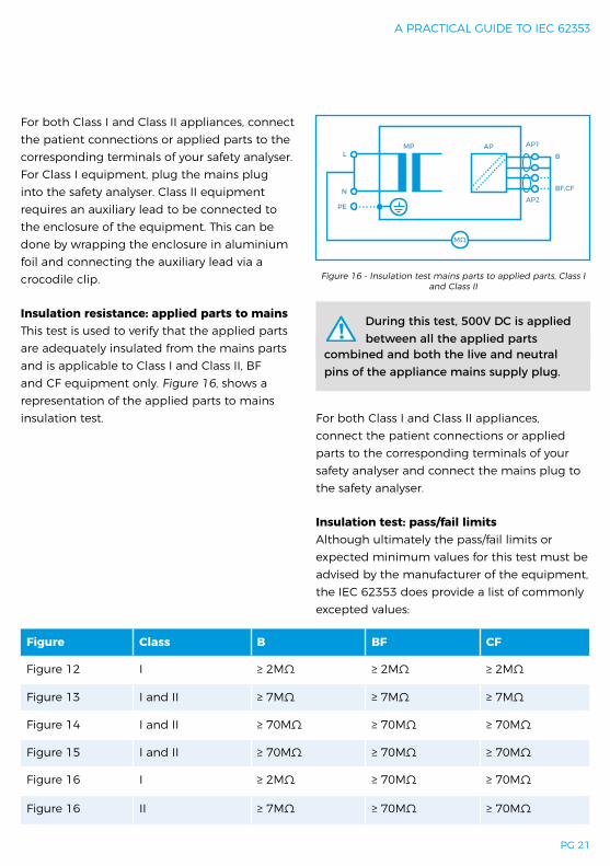
Insulation resistance: applied parts to mainsThis test is used to verify that the applied parts are adequately insulated from the mains parts and is applicable to Class I and Class II, BF and CF equipment only. Figure 16, shows a representation of the applied parts to mains insulation test.
During this test, 500V DC is applied between all the applied parts
combined and both the live and neutral pins of the appliance mains supply plug.
For both Class I and Class II appliances, connect the patient connections or applied parts to the corresponding terminals of your safety analyser and connect the mains plug to the safety analyser.
Insulation test: pass/fail limitsAlthough ultimately the pass/fail limits or expected minimum values for this test must be advised by the manufacturer of the equipment, the IEC 62353 does provide a list of commonly excepted values:
Figure 16 - Insulation test mains parts to applied parts, Class I and Class II
APB
BF,CF
MPL
N
PE
MΩ
AP1
AP2
Figure Class B BF CF
Figure 12 I ≥ 2MΩ ≥ 2MΩ ≥ 2MΩ
Figure 13 I and II ≥ 7MΩ ≥ 7MΩ ≥ 7MΩ
Figure 14 I and II ≥ 70MΩ ≥ 70MΩ ≥ 70MΩ
Figure 15 I and II ≥ 70MΩ ≥ 70MΩ ≥ 70MΩ
Figure 16 I ≥ 2MΩ ≥ 70MΩ ≥ 70MΩ
Figure 16 II ≥ 7MΩ ≥ 70MΩ ≥ 70MΩ

RIGEL MEDICAL
PG 22 TESTED, TRUSTED… WORLDWIDE.
IEC 62353 leakage measurementsAs covered in The human body, it is the level of electrical current rather than level of voltage which is the criteria for safety due to the impact of electrical currents on the human tissues. Small amounts of current which are undetectable by sensation can have a significant impact on our safety.
IEC 62353 defines two different kinds of leakage current tests:
∙ Equipment leakage current - total leakage deriving from the power supply to earth via the applied parts and enclosure, see Equipment leakage
∙ Applied part leakage current - leakage current flowing from an applied part to the enclosure or earth as a result of an external voltage on the applied part, see Applied part leakage
Method characteristicsTo ensure that a valid leakage measurement can be obtained, the IEC 62353 describes the following methods:
∙ Direct leakage - measurement of leakage current via a measuring device, placed directly in the path of the leakage current (see Direct leakage)
∙ Differential leakage - measuring the imbalance between current in the live conductor and the neutral conductor as a result of leakage current (see Differential method)
∙ Alternative Method - measurement of leakage when mains voltage is both on
the live and neutral wire (see Alternative method)
Direct leakageThe direct leakage method is identical to the method used in the IEC 60601-1 standard; measuring the true leakage through a body model (measuring device) to earth.
Benefits: ∙ Means of measuring both AC and DC
leakage current ∙ Highest accuracy compared to other
methods ∙ Potential leakage through a human body
via measuring device ∙ Direct comparison with measurements
made in accordance with IEC 60601-1
To consider: ∙ The 1kΩ resistor forming the measuring
device is interrupting the low resistance protective earth conductor, therefore causing a potential hazard when testing faulty equipment
∙ Secondary earth path(s) could lead to zero current readings (see Method characteristics)
∙ A difference in polarity of the live and neutral conductors might alter the leakage readings, as such leakage measurements must be done in each polarity of mains supply
∙ A TN (terre – neutral) system is required to ensure that the measurements are done at maximum live to earth voltage. Any voltage between neutral and earth might result in a lower reading, potentially passing faulty equipment
A PRACTICAL GUIDE TO IEC 62353
PG 23
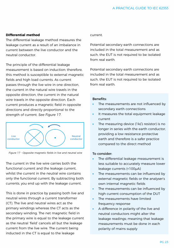
Differential methodThe differential leakage method measures the leakage current as a result of an imbalance in current between the live conductor and the neutral conductor.
The principle of the differential leakage measurement is based on induction; therefore, this method is susceptible to external magnetic fields and high load currents. As current passes through the live wire in one direction, the current in the natural wire travels in the opposite direction, the current in the natural wire travels in the opposite direction. Each current produces a magnetic field in opposite directions and directly proportional to the strength of current. See Figure 17.
The current in the live wire carries both the functional current and the leakage current, whilst the current in the neutral wire contains only the functional current. By subtracting both currents, you end up with the leakage current.
This is done in practice by passing both live and neutral wires through a current transformer (CT). The live and neutral wires act as the primary windings whereas the CT acts as the secondary winding. The net magnetic field in the primary wire is equal to the leakage current as the neutral ‘field’ cancels all but the leakage current from the live wire. The current being inducted in the CT is equal to the leakage
current.
Potential secondary earth connections are included in the total measurement and as such, the EUT is not required to be isolated from real earth.
Potential secondary earth connections are included in the total measurement and as such, the EUT is not required to be isolated from real earth.
Benefits: ∙ The measurements are not influenced by
secondary earth connections ∙ It measures the total equipment leakage
current ∙ The measuring device (1kΩ resistor) is no
longer in series with the earth conductor, providing a low resistance protective earth and therefore is a safer practice compared to the direct method
To consider: ∙ The differential leakage measurement is
less suitable to accurately measure lower leakage currents (<100µA)
∙ The measurements can be influenced by external magnetic fields or the analyser’s own internal magnetic fields
∙ The measurements can be influenced by high current consumption of the DUT
∙ The measurements have limited frequency response
∙ A difference in polarity of the live and neutral conductors might alter the leakage readings; meaning that leakage measurements must be done in each polarity of mains supply
Neutral conductor
Liveconductor
Figure 17 - Opposite magnetic fields in live and neutral wire
RIGEL MEDICAL
PG 24 TESTED, TRUSTED… WORLDWIDE.
83VU=230V50HZ
RI= 66kΩ
±2.2mA
Figure 18 - Example of current limited mains supply during alternative leakage
∙ Both direct and alternative methods provide higher accuracy and broader frequency response which is required for measuring trends in low leakage conditions
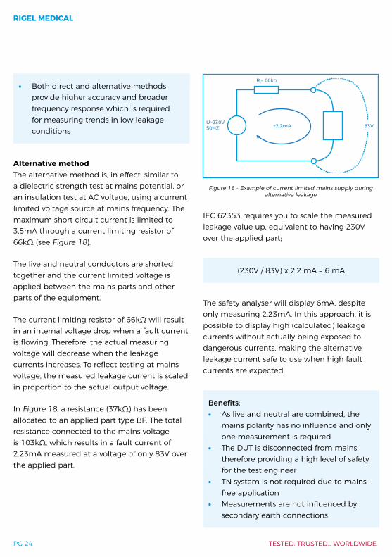
Alternative methodThe alternative method is, in effect, similar to a dielectric strength test at mains potential, or an insulation test at AC voltage, using a current limited voltage source at mains frequency. The maximum short circuit current is limited to 3.5mA through a current limiting resistor of 66kΩ (see Figure 18).
The live and neutral conductors are shorted together and the current limited voltage is applied between the mains parts and other parts of the equipment.
The current limiting resistor of 66kΩ will result in an internal voltage drop when a fault current is flowing. Therefore, the actual measuring voltage will decrease when the leakage currents increases. To reflect testing at mains voltage, the measured leakage current is scaled in proportion to the actual output voltage.
In Figure 18, a resistance (37kΩ) has been allocated to an applied part type BF. The total resistance connected to the mains voltage is 103kΩ, which results in a fault current of 2.23mA measured at a voltage of only 83V over the applied part.
IEC 62353 requires you to scale the measured leakage value up, equivalent to having 230V over the applied part;
(230V / 83V) x 2.2 mA = 6 mA
The safety analyser will display 6mA, despite only measuring 2.23mA. In this approach, it is possible to display high (calculated) leakage currents without actually being exposed to dangerous currents, making the alternative leakage current safe to use when high fault currents are expected.
Benefits: ∙ As live and neutral are combined, the
mains polarity has no influence and only one measurement is required
∙ The DUT is disconnected from mains, therefore providing a high level of safety for the test engineer
∙ TN system is not required due to mains-free application
∙ Measurements are not influenced by secondary earth connections

A PRACTICAL GUIDE TO IEC 62353
PG 25
∙ Tests can be performed from a battery powered instrument
∙ Measurements are highly repeatable and provide a good indication of deterioration in the dielectrics of the medical device under test
To consider: ∙ Equipment will not be activated,
preventing the measurement of actual leakage currents on equipment with switched circuits
Equipment leakageEquipment leakage current - total leakage deriving from the power supply to earth via the applied parts and enclosure. The equipment leakage test is applicable to Class I, Class II, type B, type BF, and type CF equipment.
Leakage measurements to IEC 62353 are done using the RMS value instead of the separate AC and DC values used in the IEC 60601-1 standard.
The IEC 62353 specifies three different methods for measuring the equipment leakage current:
∙ Direct method ∙ Differential method ∙ Alternative method
Equipment leakage: Direct methodThe direct method is identical to the method used in the IEC 60601-1.
Figure 19 and Figure 20 show a representation of the direct method.
The DUT must be positioned floating to avoid secondary earth connections influencing the measuring process.
All applied parts (B, BF & CF) and earthed (e.g. enclosure class I) and non-earthed accessible conductive parts or non-conductive accessible parts (enclosure class II) are grouped together and connected to the earth via the 1kΩ measuring device (body model).
The 1kΩ measuring device (MD – equivalent to that used in the IEC 60601 standard – see IEC 60601 body model) is positioned in the leakage return path to earth.
The test is conducted with the protective earth connection ‘interrupted’, to ensure the
APMPL(N)L
N
PE
N(L)
MD
Figure 19 - Equipment leakage direct - Class I
APMPL(N)L
N
PE
N(L)
MD
Figure 20 - Equipment leakage direct – Class II
RIGEL MEDICAL
PG 26 TESTED, TRUSTED… WORLDWIDE.
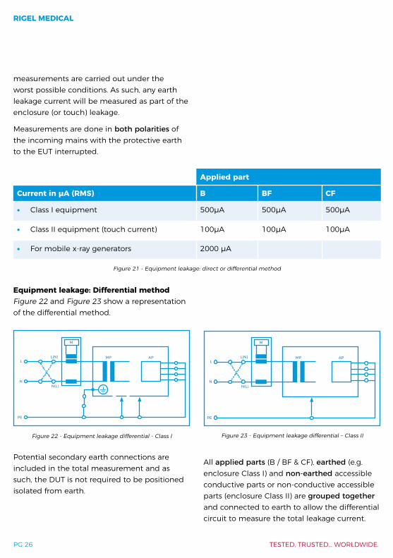
measurements are carried out under the worst possible conditions. As such, any earth leakage current will be measured as part of the enclosure (or touch) leakage.
Measurements are done in both polarities of the incoming mains with the protective earth to the EUT interrupted.
Equipment leakage: Differential methodFigure 22 and Figure 23 show a representation of the differential method.
Potential secondary earth connections are included in the total measurement and as such, the DUT is not required to be positioned isolated from earth.
All applied parts (B / BF & CF), earthed (e.g. enclosure Class I) and non-earthed accessible conductive parts or non-conductive accessible parts (enclosure Class II) are grouped together and connected to earth to allow the differential circuit to measure the total leakage current.
Applied part
Current in µA (RMS) B BF CF
∙ Class I equipment 500µA 500µA 500µA
∙ Class II equipment (touch current) 100µA 100µA 100µA
∙ For mobile x-ray generators 2000 µA
Figure 22 - Equipment leakage differential - Class I Figure 23 - Equipment leakage differential – Class II
Figure 21 - Equipment leakage: direct or differential method
APMP
M
L(N)L
N
PE
N(L)
APMP
M
L(N)L
N
PE
N(L)
A PRACTICAL GUIDE TO IEC 62353
PG 27
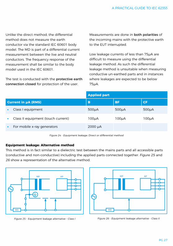
Unlike the direct method, the differential method does not measure the earth conductor via the standard IEC 60601 body model. The MD is part of a differential current measurement between the live and neutral conductors. The frequency response of the measurement shall be similar to the body model used in the IEC 60601.
The test is conducted with the protective earth connection closed for protection of the user.
Measurements are done in both polarities of the incoming mains with the protective earth to the EUT interrupted.
Low leakage currents of less than 75µA are difficult to measure using the differential leakage method. As such the differential leakage method is unsuitable when measuring conductive un-earthed parts and in instances where leakages are expected to be below 75µA.
Figure 24 - Equipment leakage: Direct or differential method
Applied part
Current in µA (RMS) B BF CF
∙ Class I equipment 500µA 500µA 500µA
∙ Class II equipment (touch current) 100µA 100µA 100µA
∙ For mobile x-ray generators 2000 µA
Figure 26 - Equipment leakage alternative - Class IIFigure 25 - Equipment leakage alternative - Class I
Equipment leakage: Alternative methodThis method is in fact similar to a dielectric test between the mains parts and all accessible parts (conductive and non-conductive) including the applied parts connected together. Figure 25 and 26 show a representation of the alternative method.
APMP
MD
APMP
MD

RIGEL MEDICAL
PG 28 TESTED, TRUSTED… WORLDWIDE.
The test is performed using a current limited (3.5mA) mains potential sinusoidal 50Hz signal (60Hz where this is the mains frequency).
As live and neutral are shortened, the DUT is not directly connected to the mains potential. As such, mains reversal is not applicable and the EUT is not required to be positioned isolated from earth.
All applied parts, and earthed (e.g. enclosure Class I) and non-earthed accessible conductive parts or non-conductive accessible parts (enclosure Class II) are grouped together and connected to the mains parts via the 1kΩ measuring device (body model) and voltage source.
Applied part leakageThe applied part leakage test measures the total leakage deriving from the combined patient connections within an applied part to earth and any conductive or non-conductive parts on the enclosure (either connected or isolated from earth) under the fault condition mains on the applied parts.
The applied part leakage test is applicable to floating type (BF & CF) applied parts only either Class I or Class II.
All patient connections of a single function within an applied part shall be connected together (BF & CF) and measured one at the time.
Applied parts (and patient connections) are not part of the measurement and shall be left floating i.e. not connected to real earth.
The test is conducted by applying a current limited (3.5mA) mains potential sinusoidal 50Hz signal (60Hz where this is the mains frequency) between the applied part, the enclosure and earth connection of the EUT that is connected to real earth.
Leakage measurements to IEC 62353 are done using the RMS value instead of the separate AC and DC values used in the IEC 60601-1 standard.
The IEC 62353 / applied part leakage can be performed in two different methods;
∙ Direct method ∙ Alternative method
Applied part
Current in µA (RMS) B BF CF
∙ Class I equipment 1000µA 1000µA 1000µA
∙ Class II equipment (touch current) 500µA 500µA 500µA
∙ For mobile x-ray generators 5000 µA
Figure 27 - Equipment leakage: Alternative method
A PRACTICAL GUIDE TO IEC 62353
PG 29
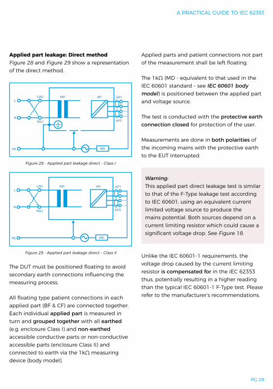
Applied part leakage: Direct methodFigure 28 and Figure 29 show a representation of the direct method.
The DUT must be positioned floating to avoid secondary earth connections influencing the measuring process.
All floating type patient connections in each applied part (BF & CF) are connected together. Each individual applied part is measured in turn and grouped together with all earthed (e.g. enclosure Class I) and non-earthed accessible conductive parts or non-conductive accessible parts (enclosure Class II) and connected to earth via the 1kΩ measuring device (body model).
Applied parts and patient connections not part of the measurement shall be left floating.
The 1kΩ (MD - equivalent to that used in the IEC 60601 standard – see IEC 60601 body model) is positioned between the applied part and voltage source.
The test is conducted with the protective earth connection closed for protection of the user.
Measurements are done in both polarities of the incoming mains with the protective earth to the EUT interrupted.
Warning: This applied part direct leakage test is similar to that of the F-Type leakage test according to IEC 60601, using an equivalent current limited voltage source to produce the mains potential. Both sources depend on a current limiting resistor which could cause a significant voltage drop. See Figure 18.
Unlike the IEC 60601-1 requirements, the voltage drop caused by the current limiting resistor is compensated for in the IEC 62353 thus, potentially resulting in a higher reading than the typical IEC 60601-1 F-Type test. Please refer to the manufacturer’s recommendations.
Figure 28 - Applied part leakage direct - Class I
Figure 29 - Applied part leakage direct – Class II
APMPL(N)L
NN(L)
MD
AP2
PE
AP1
APMPL(N)L
NN(L)
MDPE
AP2
AP1
RIGEL MEDICAL
PG 30 TESTED, TRUSTED… WORLDWIDE.
Applied part
Current in µA (RMS) B BF CF
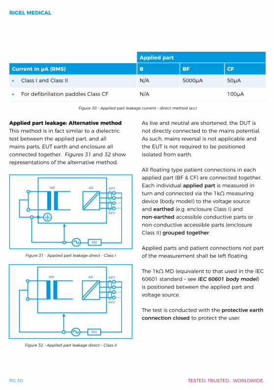
∙ Class I and Class II N/A 5000µA 50µA
∙ For defibrillation paddles Class CF N/A 100µA
Figure 30 - Applied part leakage current - direct method (a.c)
Applied part leakage: Alternative method This method is in fact similar to a dielectric test between the applied part, and all mains parts, EUT earth and enclosure all connected together. Figures 31 and 32 show representations of the alternative method.
As live and neutral are shortened, the DUT is not directly connected to the mains potential. As such, mains reversal is not applicable and the EUT is not required to be positioned isolated from earth.
All floating type patient connections in each applied part (BF & CF) are connected together. Each individual applied part is measured in turn and connected via the 1kΩ measuring device (body model) to the voltage source and earthed (e.g. enclosure Class I) and non-earthed accessible conductive parts or non-conductive accessible parts (enclosure Class II) grouped together.
Applied parts and patient connections not part of the measurement shall be left floating.
The 1kΩ MD (equivalent to that used in the IEC 60601 standard – see IEC 60601 body model) is positioned between the applied part and voltage source.
The test is conducted with the protective earth connection closed to protect the user.
Figure 31 - Applied part leakage direct - Class I
Figure 32 - Applied part leakage direct – Class II
APMP
MD
AP2
AP1
APMP
MD
AP2
AP1

A PRACTICAL GUIDE TO IEC 62353
PG 31
Secondary earth problemsDue to the fact that electrical currents follow the path of least resistance (much like water does), it is important to realise that secondary earth path connections could influence the measurements of leakage currents.
∙ Secondary connections are typical with: - Equipment bolted to steel enforced
concrete floor (e.g. dentist chairs, MRI) - Equipment connected to gas or water
supply - Equipment that is part of a medical
electrical system - Equipment connected to PC or printer
Compared to the 1kΩ resistance of the body model, a secondary earth path is substantially lower. As such, electrical currents are mostly flowing down the secondary earth path, away from the safety analyser, as shown in Figure 34, which represents an example of a secondary earth connection via a data cable.
This will result in a zero reading on the safety analyser and could potentially pass a dangerous medical device.
In case a secondary earth path exists, the Rigel 288+ and Rigel 62353+ devices will provide the user with an error message as shown in Figure 35.
Applied part
Current in µA (RMS) B BF CF
∙ Class I and Class II N/A 5000µA 50µA
∙ For defibrillation paddles class CF N/A 100µA
Figure 33 - Applied part leakage current - alternative method (a.c)
Figure 34 - Example showing leakage current flowing away via a secondary earth connection
AP
<5Ω
MPL
N
Display1000Ω
MD
Figure 35 - Secondary earth path error message on Rigel 288+ and Rigel 62353+ devices
A]
IEC 62353Direct Equipment Lkg
AlertSecondary earth path
detected. Please verify testsetup.
0008
2s
RIGEL MEDICAL
PG 32 TESTED, TRUSTED… WORLDWIDE.
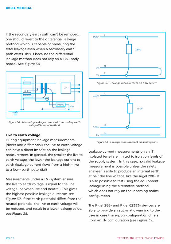
Figure 36 - Measuring leakage current with secondary earth using differential method
AP
<5Ω
L
N
Display
Differential
If the secondary earth path can’t be removed, one should revert to the differential leakage method which is capable of measuring the total leakage even when a secondary earth path exists. This is because the differential leakage method does not rely on a 1kΩ body model. See Figure 36.
Live to earth voltageDuring equipment leakage measurements (direct and differential), the live to earth voltage can have a direct impact on the leakage measurement. In general, the smaller the live to earth voltage, the lower the leakage current to earth (leakage current flows from a high – live to a low – earth potential).
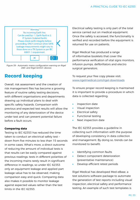
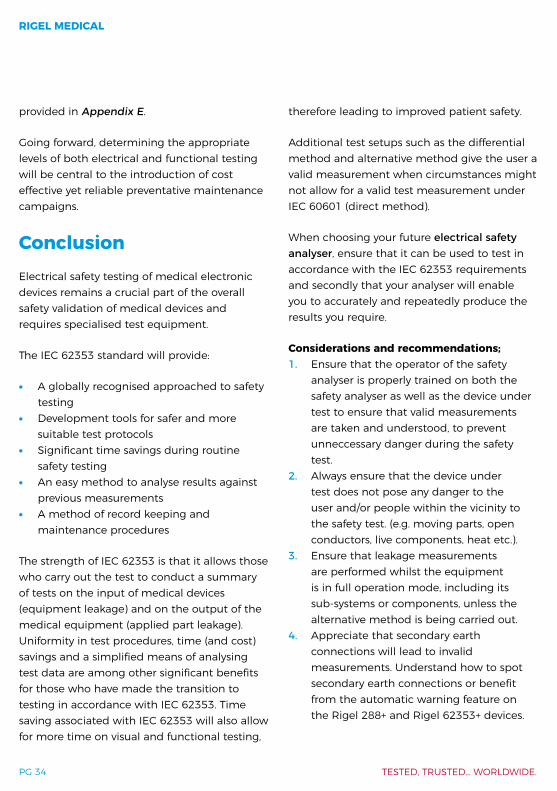
Measurements under a TN (system ensure the live to earth voltage is equal to the line voltage (between live and neutral). This gives the highest possible leakage outcome, see Figure 37. If the earth potential differs from the neutral potential, the live to earth voltage will be reduced, and result in a lower leakage value, see Figure 38.
Leakage current measurements on an IT (isolated terre) are limited to isolation levels of the supply system. In this case, no valid leakage measurement is possible unless the safety analyser is able to produce an internal earth at half the line voltage, like the Rigel 288+. It is also possible to test using the equipment leakage using the alternative method which does not rely on the incoming mains configuration.
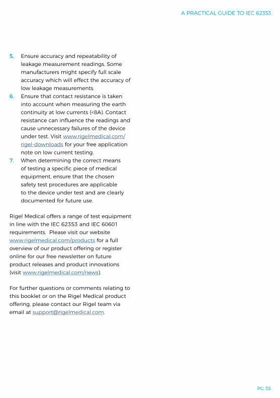
The Rigel 288+ and Rigel 62353+ devices are able to provide an automatic warning to the user in case the supply configuration differs from an TN configuration (see Figure 39).
Figure 37 - Leakage measurement on a TN system
L
230V
230V
0V
0V
N
E
Figure 38 - Leakage measurement on an IT system
L
130V
230V
100V
0V
E
N
A PRACTICAL GUIDE TO IEC 62353
PG 33
Record keepingOverall, risk assessment and the creation of risk management files has become a growing feature of routine safety testing decisions, with different organisations and departments drawing up individual plans to deal with specific safety hazards. Comparison with previous and expected test results will allow the monitoring of any deterioration of the device under test and can prevent potential failure before a fault occurs.
Comparing dataTesting to IEC 62353 has reduced the time taken to conduct an electrical safety test – down from five minutes to less than 15 seconds in some cases. What’s more, a direct outcome of reducing the amount of individual tests is that results can be easily compared against previous readings: tests in different polarities of the incoming mains rarely result in significant difference in readings, so under IEC 62353 only an equipment leakage and applied part leakage value has to be observed, making comparison easy and quick. Comparing data also makes it possible to monitor leakage against expected values rather than the test limits in the IEC 62353.
Electrical safety testing is only part of the total service carried out on medical equipment. Once the safety is accessed, the functionality is verified and recorded before the equipment is returned for use on patients.
Rigel Medical has produced a range of informative booklets that cover the performance verification of vital signs monitors, infusion pumps, defibrillators and electro surgical generators.
To request your free copy please visit: www.rigelmedical.com/rigel-downloads
To ensure proper record keeping is maintained it is important to provide a procedure in which data is collected regarding:
∙ Inspection date ∙ Visual inspection ∙ Electrical safety ∙ Functional testing ∙ Next inspection date
The IEC 62353 provides a guideline in collecting such information with the purpose of developing consistency in data collection and management. By doing so, trends can be monitored to benefit:
∙ Identifying common faults ∙ Detect component deterioration
(preventative maintenance) ∙ Develop efficient retest periods
Rigel Medical has developed Med-eBase, a test solutions software package to automate the generation of test reports including visual inspection, electrical safety and performance testing. An example of such test templates is
Figure 39 - Automatic mains configuration warning on Rigel 288+ and Rigel 62353+ devices
WarningNo incoming Earth line.
Can be used by:- 1. Earth Fault or 2.IT System (Isolated Earth)
Please check earth integrity before proceeding. ONLY continue when SAFE.Leakage measurements might vary to those done on a TN System as per IEC
60601-1 requirement.
RIGEL MEDICAL
PG 34 TESTED, TRUSTED… WORLDWIDE.
provided in Appendix E.
Going forward, determining the appropriate levels of both electrical and functional testing will be central to the introduction of cost effective yet reliable preventative maintenance campaigns.
ConclusionElectrical safety testing of medical electronic devices remains a crucial part of the overall safety validation of medical devices and requires specialised test equipment.
The IEC 62353 standard will provide:
∙ A globally recognised approached to safety testing
∙ Development tools for safer and more suitable test protocols
∙ Significant time savings during routine safety testing
∙ An easy method to analyse results against previous measurements
∙ A method of record keeping and maintenance procedures
The strength of IEC 62353 is that it allows those who carry out the test to conduct a summary of tests on the input of medical devices (equipment leakage) and on the output of the medical equipment (applied part leakage). Uniformity in test procedures, time (and cost) savings and a simplified means of analysing test data are among other significant benefits for those who have made the transition to testing in accordance with IEC 62353. Time saving associated with IEC 62353 will also allow for more time on visual and functional testing,
therefore leading to improved patient safety.
Additional test setups such as the differential method and alternative method give the user a valid measurement when circumstances might not allow for a valid test measurement under IEC 60601 (direct method).
When choosing your future electrical safety analyser, ensure that it can be used to test in accordance with the IEC 62353 requirements and secondly that your analyser will enable you to accurately and repeatedly produce the results you require.
Considerations and recommendations;1. Ensure that the operator of the safety
analyser is properly trained on both the safety analyser as well as the device under test to ensure that valid measurements are taken and understood, to prevent unneccessary danger during the safety test.
2. Always ensure that the device under test does not pose any danger to the user and/or people within the vicinity to the safety test. (e.g. moving parts, open conductors, live components, heat etc.).
3. Ensure that leakage measurements are performed whilst the equipment is in full operation mode, including its sub-systems or components, unless the alternative method is being carried out.
4. Appreciate that secondary earth connections will lead to invalid measurements. Understand how to spot secondary earth connections or benefit from the automatic warning feature on the Rigel 288+ and Rigel 62353+ devices.
A PRACTICAL GUIDE TO IEC 62353
PG 35
5. Ensure accuracy and repeatability of leakage measurement readings. Some manufacturers might specify full scale accuracy which will effect the accuracy of low leakage measurements.
6. Ensure that contact resistance is taken into account when measuring the earth continuity at low currents (<8A). Contact resistance can influence the readings and cause unnecessary failures of the device under test. Visit www.rigelmedical.com/rigel-downloads for your free application note on low current testing.
7. When determining the correct means of testing a specific piece of medical equipment, ensure that the chosen safety test procedures are applicable to the device under test and are clearly documented for future use.
Rigel Medical offers a range of test equipment in line with the IEC 62353 and IEC 60601 requirements. Please visit our website www.rigelmedical.com/products for a full overview of our product offering or register online for our free newsletter on future product releases and product innovations (visit www.rigelmedical.com/news).
For further questions or comments relating to this booklet or on the Rigel Medical product offering, please contact our Rigel team via email at [email protected].
RIGEL MEDICAL
PG 36 TESTED, TRUSTED… WORLDWIDE.
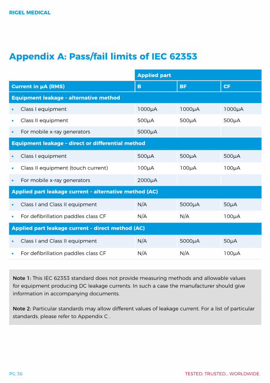
Appendix A: Pass/fail limits of IEC 62353
Note 1: This IEC 62353 standard does not provide measuring methods and allowable values for equipment producing DC leakage currents. In such a case the manufacturer should give information in accompanying documents.
Note 2: Particular standards may allow different values of leakage current. For a list of particular standards, please refer to Appendix C .
Applied part
Current in µA (RMS) B BF CF
Equipment leakage – alternative method
∙ Class I equipment 1000µA 1000µA 1000µA
∙ Class II equipment 500µA 500µA 500µA
∙ For mobile x-ray generators 5000µA
Equipment leakage – direct or differential method
∙ Class I equipment 500µA 500µA 500µA
∙ Class II equipment (touch current) 100µA 100µA 100µA
∙ For mobile x-ray generators 2000µA
Applied part leakage current – alternative method (AC)
∙ Class I and Class II equipment N/A 5000µA 50µA
∙ For defibrillation paddles class CF N/A N/A 100µA
Applied part leakage current – direct method (AC)
∙ Class I and Class II equipment N/A 5000µA 50µA
∙ For defibrillation paddles class CF N/A N/A 100µA

A PRACTICAL GUIDE TO IEC 62353
PG 37
Appendix B: IEC 60601-1 collateral standardsTable 1 – IEC 60601 Collateral Standards(© IEC Geneva, Switzerland)
IEC 60601-1 Medical electrical equipment - Part 1: General requirements for basic safety and essential performance
IEC 60601-1-2 Medical electrical equipment - Part 1-2: General requirements for basic safety and essential performance - Collateral Standard: Electromagnetic disturbances - Requirements and tests
IEC 60601-1-3 Medical electrical equipment - Part 1-3: General requirements for basic safety and essential performance - Collateral Standard: Radiation protection in diagnostic X-ray equipment
EC 60601-1-6 Medical electrical equipment - Part 1-6: General requirements for basic safety and essential performance - Collateral standard: Usability
IEC 60601-1-8 Medical electrical equipment - Part 1-8: General requirements for basic safety and essential performance - Collateral Standard: General requirements, tests and guidance for alarm systems in medical electrical equipment and medical electrical systems
IEC 60601-1-9Medical electrical equipment - Part 1-9: General requirements for basic safety and essential performance - Collateral Standard: Requirements for environmentally conscious design
IEC 60601-1-10Medical electrical equipment - Part 1-10: General requirements for basic safety and essential performance - Collateral Standard: Requirements for the development of physiologic closed-loop controllers
IEC 60601-1-11Medical electrical equipment – Part 1-11: General requirements for basic safety and essential performance – Collateral Standard: Requirements for medical electrical equipment and medical electrical systems used in the home healthcare environment
RIGEL MEDICAL
PG 38 TESTED, TRUSTED… WORLDWIDE.
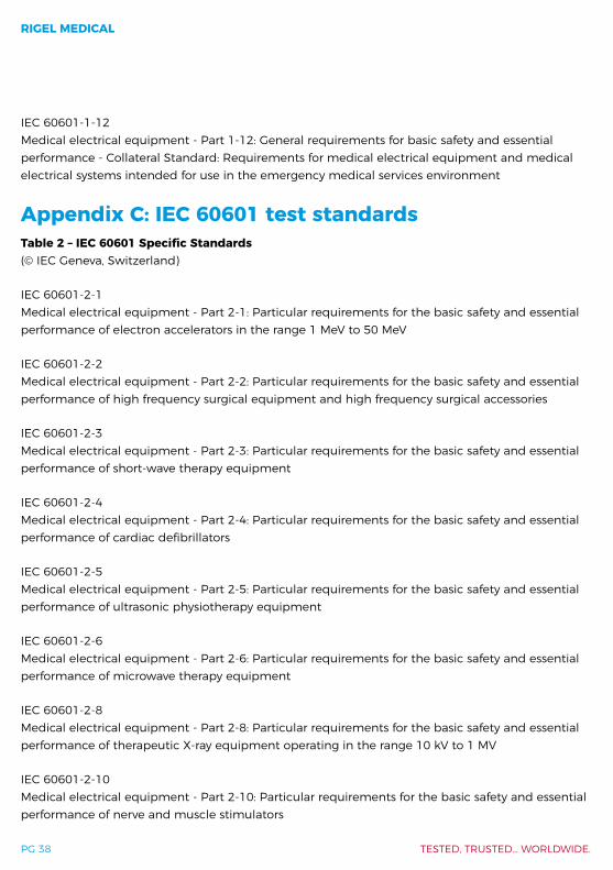
IEC 60601-1-12Medical electrical equipment - Part 1-12: General requirements for basic safety and essential performance - Collateral Standard: Requirements for medical electrical equipment and medical electrical systems intended for use in the emergency medical services environment
Appendix C: IEC 60601 test standardsTable 2 – IEC 60601 Specific Standards(© IEC Geneva, Switzerland)
IEC 60601-2-1 Medical electrical equipment - Part 2-1: Particular requirements for the basic safety and essential performance of electron accelerators in the range 1 MeV to 50 MeV
IEC 60601-2-2Medical electrical equipment - Part 2-2: Particular requirements for the basic safety and essential performance of high frequency surgical equipment and high frequency surgical accessories
IEC 60601-2-3Medical electrical equipment - Part 2-3: Particular requirements for the basic safety and essential performance of short-wave therapy equipment
IEC 60601-2-4 Medical electrical equipment - Part 2-4: Particular requirements for the basic safety and essential performance of cardiac defibrillators
IEC 60601-2-5Medical electrical equipment - Part 2-5: Particular requirements for the basic safety and essential performance of ultrasonic physiotherapy equipment
IEC 60601-2-6Medical electrical equipment - Part 2-6: Particular requirements for the basic safety and essential performance of microwave therapy equipment
IEC 60601-2-8 Medical electrical equipment - Part 2-8: Particular requirements for the basic safety and essential performance of therapeutic X-ray equipment operating in the range 10 kV to 1 MV
IEC 60601-2-10 Medical electrical equipment - Part 2-10: Particular requirements for the basic safety and essential performance of nerve and muscle stimulators
A PRACTICAL GUIDE TO IEC 62353
PG 39
IEC 60601-2-11Medical electrical equipment - Part 2-11: Particular requirements for the basic safety and essential performance of gamma beam therapy equipment
IEC 60601-2-16Medical electrical equipment - Part 2-16: Particular requirements for basic safety and essential performance of haemodialysis, haemodiafiltration and haemofiltration equipment
IEC 60601-2-17 Medical electrical equipment - Part 2-17: Particular requirements for the basic safety and essential performance of automatically-controlled brachytherapy after loading equipment
IEC 60601-2-18Medical electrical equipment - Part 2-18: Particular requirements for the basic safety and essential performance of endoscopic equipment
IEC 60601-2-19 Medical electrical equipment - Part 2-19: Particular requirements for the basic safety and essential performance of infant incubators
IEC 60601-2-20Medical electrical equipment - Part 2-20: Particular requirements for the basic safety and essential performance of infant transport incubators
IEC 60601-2-21 Medical electrical equipment - Part 2-21: Particular requirements for the basic safety and essential performance of infant radiant warmers
IEC 60601-2-22Medical electrical equipment - Part 2-22: Particular requirements for basic safety and essential performance of surgical, cosmetic, therapeutic and diagnostic laser equipment
IEC 60601-2-23Medical electrical equipment - Part 2-23: Particular requirements for the basic safety and essential performance of transcutaneous partial pressure monitoring equipment
IEC 60601-2-24Medical electrical equipment - Part 2-24: Particular requirements for the basic safety and essential performance of infusion pumps and controllers

RIGEL MEDICAL
PG 40 TESTED, TRUSTED… WORLDWIDE.
IEC 60601-2-25Medical electrical equipment - Part 2-25: Particular requirements for the basic safety and essential performance of electrocardiographs
IEC 60601-2-26Medical electrical equipment - Part 2-26: Particular requirements for the basic safety and essential performance of electroencephalographs
IEC 60601-2-27Medical electrical equipment - Part 2-27: Particular requirements for the basic safety and essential performance of electrocardiographic monitoring equipment
IEC 60601-2-28Medical electrical equipment - Part 2-28: Particular requirements for the basic safety and essential performance of X-ray tube assemblies for medical diagnosis
IEC 60601-2-29Medical electrical equipment - Part 2-29: Particular requirements for the basic safety and essential performance of radiotherapy simulators
IEC 60601-2-31Medical electrical equipment - Part 2-31: Particular requirements for the basic safety and essential performance of external cardiac pacemakers with internal power source
IEC 60601-2-33 Medical electrical equipment - Part 2-33: Particular requirements for the basic safety and essential performance of magnetic resonance equipment for medical diagnosis
IEC 60601-2-34Medical electrical equipment - Part 2-34: Particular requirements for the basic safety and essential performance of invasive blood pressure monitoring equipment
IEC 60601-2-36Medical electrical equipment - Part 2-36: Particular requirements for the basic safety and essential performance of equipment for extra corporeally induced lithotripsy
IEC 60601-2-37Medical electrical equipment - Part 2-37: Particular requirements for the basic safety and essential performance of ultrasonic medical diagnostic and monitoring equipment
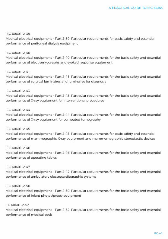
A PRACTICAL GUIDE TO IEC 62353
PG 41
IEC 60601-2-39 Medical electrical equipment - Part 2-39: Particular requirements for basic safety and essential performance of peritoneal dialysis equipment
IEC 60601-2-40Medical electrical equipment - Part 2-40: Particular requirements for the basic safety and essential performance of electromyographs and evoked response equipment
IEC 60601-2-41Medical electrical equipment - Part 2-41: Particular requirements for the basic safety and essential performance of surgical luminaires and luminaires for diagnosis
IEC 60601-2-43Medical electrical equipment - Part 2-43: Particular requirements for the basic safety and essential performance of X-ray equipment for interventional procedures
IEC 60601-2-44 Medical electrical equipment - Part 2-44: Particular requirements for the basic safety and essential performance of X-ray equipment for computed tomography
IEC 60601-2-45Medical electrical equipment - Part 2-45: Particular requirements for basic safety and essential performance of mammographic X-ray equipment and mammomagraphic stereotactic devices
IEC 60601-2-46 Medical electrical equipment - Part 2-46: Particular requirements for the basic safety and essential performance of operating tables
IEC 60601-2-47Medical electrical equipment - Part 2-47: Particular requirements for the basic safety and essential performance of ambulatory electrocardiographic systems
IEC 60601-2-50Medical electrical equipment - Part 2-50: Particular requirements for the basic safety and essential performance of infant phototherapy equipment
EC 60601-2-52 Medical electrical equipment - Part 2-52: Particular requirements for the basic safety and essential performance of medical beds

RIGEL MEDICAL
PG 42 TESTED, TRUSTED… WORLDWIDE.
IEC 60601-2-54Medical electrical equipment - Part 2-54: Particular requirements for the basic safety and essential performance of X-ray equipment for radiography and radioscopy
IEC 60601-2-57 Medical electrical equipment - Part 2-57: Particular requirements for the basic safety and essential performance of non-laser light source equipment intended for therapeutic, diagnostic, monitoring and cosmetic/aesthetic use
IEC 60601-2-62Medical electrical equipment - Part 2-62: Particular requirements for the basic safety and essential performance of high intensity therapeutic ultrasound (HITU) equipment
IEC 60601-2-63Medical electrical equipment - Part 2-63: Particular requirements for the basic safety and essential performance of dental extra-oral X-ray equipment
IEC 60601-2-64Medical electrical equipment - Part 2-64: Particular requirements for the basic safety and essential performance of light ion beam medical electrical equipment
IEC 60601-2-65 Medical electrical equipment - Part 2-65: Particular requirements for the basic safety and essential performance of dental intra-oral X-ray equipment
IEC 60601-2-66Medical electrical equipment - Part 2-66: Particular requirements for the basic safety and essential performance of hearing instruments and hearing instrument systems
IEC 60601-2-68Electrical medical equipment - Part 2-68: Particular requirements for the basic safety and essential performance of X-ray-based image-guided radiotherapy equipment for use with electron accelerators, light ion beam therapy equipment and radionuclide beam therapy equipment
IEC 60601-2-75Medical electrical equipment - Part 2-75: Particular requirements for the basic safety and essential performance of photodynamic therapy and photodynamic diagnosis equipment
IEC 60601-2-76Medical electrical equipment - Part 2-76: Particular requirements for the basic safety and essential performance of low energy ionized gas haemostasis equipment
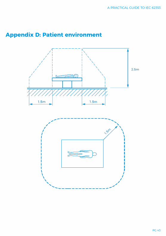
A PRACTICAL GUIDE TO IEC 62353
PG 43
Appendix D: Patient environment

RIGEL MEDICAL
PG 44 TESTED, TRUSTED… WORLDWIDE.
Appendix E: Example documentation template
i “Harm” is a defined term in ISO 14971:2000 as “physical injury or damage to the health of people or animals, or damage to property or the Environment”ii In IEC 60601, safe levels of current are defined as 10µA AC / DC for CF applied parts and 100µA AC / DC for B / BF applied parts and touch current. Earth leakage limits are higher at 500µA RMS for equipment with conductive accessible parts that may become live under a fault condition and 5000µA RMS for earthed devices with no conductive accessible parts. Under fault conditions, higher values are allowed.iii A free application note on this subject is available at; www.rigelmedical.com/rigel-downloads
iv Comparing the tests of a 12 lead ECG (CF) monitor which requires 290 AC and DC leakage readings under IEC 60601 (excluding SIP-SOP) and only 4 leakage readings in IEC 62353.v Information gathered by Rigel Medical during over 40 international seminars on IEC 62353.
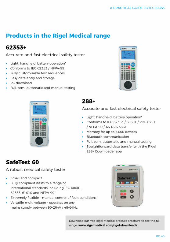
A PRACTICAL GUIDE TO IEC 62353
PG 45
288+Accurate and fast electrical safety tester
∙ Light, handheld, battery operation* ∙ Conforms to IEC 62353 / 60601 / VDE 0751
/ NFPA-99 / AS-NZS 3551 ∙ Memory for up to 5,000 devices ∙ Bluetooth communication ∙ Full, semi-automatic and manual testing ∙ Straightforward data transfer with the Rigel
288+ Downloader app
62353+Accurate and fast electrical safety tester
∙ Light, handheld, battery operation* ∙ Conforms to IEC 62353 / NFPA-99 ∙ Fully customisable test sequences ∙ Easy data entry and storage ∙ PC download ∙ Full, semi-automatic and manual testing
Products in the Rigel Medical range
SafeTest 60A robust medical safety tester
∙ Small and compact ∙ Fully compliant (tests to a range of
international standards including IEC 60601,62353, 61010 and NFPA-99)
∙ Extremely flexible - manual control of fault conditions ∙ Versatile multi voltage - operates on any
mains supply between 90-264V / 48-64Hz
Download our free Rigel Medical product brochure to see the full range: www.rigelmedical.com/rigel-downloads

RIGEL MEDICAL
PG 46 TESTED, TRUSTED… WORLDWIDE.
Accessories and services from Rigel Medical
AccessoriesHaving the right accessories can streamline your testing processes and help you get the most from your instrument. Our range of accessories includes scanners, Bluetooth enabled printers, a variety of leads and adaptors, pass/fail labels and verification units.
To see the full range of Rigel Medical accessories available, visit www.rigelmedical.com/accessories
TrainingAlongside our commitment to quality, we also offer peace of mind to our customers who know that help and advice is always available. Part of that offering includes training to support and help you get the most from your instrument.
Contact us directly to find out more.
Online resources & supportAt Rigel Medical we take pride in giving you all of the tools to make your life easier. We have a host of online resources and technical support features on our website including, FAQs, interactive videos and helpful how-to guides.
www.rigelmedical.com/support
Service, calibration & repairRigel Medical can also take care of your test and measurement equipment by providing calibration services (including on-site calibration), service, spares and repairs. Extend the life and quality of your instruments by contacting us for a no-obligation quote, wherever you are in the world.
www.rigelmedical.com/service-centre

A PRACTICAL GUIDE TO IEC 62353
PG 47
Notes

www.rigelmedical.com Rev 4.1
Seaward, 15 -18 Bracken Hill, South West Industrial Estate, Peterlee, County Durham, SR8 2SW. United Kingdom
T: +44 (0) 191 586 3511 E: [email protected]
Rigel Medical Rigel Medical Rigel Medical Rigel Medical