a prototype of fine granularity lead-scintillating fiber
TRANSCRIPT

P. Branchini High granularity Pb-SciFi calorimeter 1
A prototype of fine granularity lead-scintillatingfiber calorimeter with imaging read-out
P.Branchini, F.Ceradini, B.Di Micco, A. PasseriINFN Roma Tre and Dipartimento di Fisica Università Roma Tre
and G.CorradiINFN, Laboratori Nazionali di Frascati
11° Topical Seminar On Innovative Particle and Radiation Detectors1-4 October 2008, Siena Italy

P. Branchini 2
Sampling fraction 12 %
The starting point: the KLOE Calorimeter
σE/E = 5.7% / √E(GeV)σT = 54 ps / √E(GeV) ⊕ 50 ps PID mostly from TOF
Light readout in 4.4x4.4 cm2 cells on both sides via light-guides + fine mesh PMs
Excellent performances :

P. Branchini 3
MotivationExploit the KLOE calorimeter homogeneity to build a dense imaging device.Accurate cluster shape reconstruction would allow:
• efficient PID• near energy depositions separation• study details of the energy release process for different particles types and tune clustering algorithms accordingly.
Note: this idea has started in the KLOE-2 project, but its implementation into an upgrade of the KLOE calorimeter turned ou to be very difficult. Then it has to be considered an independent development.
two electrons200 MeVspaced by 4.4 cm
two muons200 MeVspaced by 4.4 cm
Example from detailed FLUKAsimulation:

The concept : thin light guides + multi-anode PMs
3 x 5 4.2x4.2 cm2 cells → 240 small cells 1.05x1.05 cm2
A KLOE calorimeter prototype was availableStandard light readout already present on one side: 15 cells 4.2 x 4.2 cm2 over 5 planes,each instrumented with a standard 1” PM.
23 cm13
cm52 cm
Standard readout side
Our project:
• Collect the light with segmented guides• Detect the light with multianode PMs 1 KLOE cell → 16 pixels

P. Branchini 5
Hamamatsu R8900-M16
Window material: Borosilicate glassArrangement and Type: 4 x 4 grid Number of channels: 16 (each 5.7x5.7mm2)Effective Window Area: 23.5x23.5mm2
Photocathode material: BialkaliSpectral response range: 300 to 650 nm
The multi-anode PM
Compact designOperation HV: 800-900 VA signal with sum of all the 16 last dynodesis also providedUp to 30% gain variation between the 16 pixels
We purchased 12 standard R8900 + 3 with higher quantum efficiency

A.Passeri 6
Multi anode signal pre-amplification stage
A dedicated 16+1 channel pre-amplification stage has been developedusing simple inverting x10 amplifiers.Positive signals are needed to be able to use the KLOE electronic chain.
16 ch HV distribution board also produced
PMsocket
Preamp stage
Test version

P. Branchini 7
A ps laser pulse used toilluminate single pixels and studythe multi-anode response.
Single channel
Multi anode characterization
Laser pulse
Linearity
colle
cted
cha
rge
(pC
)
Laser power (a.u.)

P. Branchini 8
Gain (non) uniformity
For each channel the response has been measured relatively to the one @ 500 V
• Slopes with HV are essentially the same• Offset is quite different from channel to channel

P. Branchini 9
Gain variation @ 800 V
Gain non-uniformity measured for all our multianodes. Similar behaviour always found
Two sample cases :

P. Branchini 10
Cross talkLaser pulse injected in individual pixels, Charge response measured in all the others.
1 8 161
8
16 1
10-1
10-2
For each PM we obtain a 16x16 cross talk matrix:
Electronic cross talk between nearby channels can be as much as few %
Non adjacent channels have almostnegligible cross talk

P. Branchini 11
Want to map 16 contiguous cells 1.05x1.05 cm2
into 16 cells 0.53x0.53 cm2 each separated by a 0.11 cm dead zone(multinode cell area is indeed 0.57x0.57 cm2).UV transparent plexiglass BC800 has been used, to fully match the R8900 spectral response
Not trivial mechanics: • all surfaces at different angles• guides are 6 cm long and touch each other only on the calorimeter surface.• a small aluminum grid keeps the 16 guides in place at the PM side
Light guides

P. Branchini 12
Light guides: final product
No black painting or envelopes on individual guides. Air/plexiglass surface considered the best compromise.Optical cross talk will have to be checked out.

P. Branchini 13
Final assembly in a 3 x 5 matrixReady to be glued on the calorimeter surface

P. Branchini 14
calorimeter
Segmented light guides
PM case
Multianode
socket
electronics
Full mechanical design

P. Branchini 15
PM case holds also HV distribution and preamp board
The full case is light tight

P. Branchini 16
Prototype mounted on a support thatallows 1800 rotation

P. Branchini 17
Finally the optical contact !

P. Branchini 18
Cross talk : electronic vs optical
We dismantled the opposite side light readout system (later on we reinstalled it).
We injected the ligh pulse on individual fibers on this now free calo side andstudy the response of the pixels on the other side:
Single multi anode cross talkconfirms what previously observed:few % on nearby channels.
The response of the two nearest rowof the adjacent PM show reallyNegligible optical cross talk !!!

P. Branchini 19
Readout and Data acquisition
It is fully made with KLOE electronics:
• signals are first splitted, discriminatedand summed (SDS boards)
• KLOE ADCs and TDCs are then usedto digitize them
• DAQ goes via asyncronous readoutUsing 2 custom buses and a chain ofROCKs (read out controller for KLOE)
• online CPU is the only new element:a Motorola MVME6100
• Trigger exploits the signal sums provided By SDS, but it is simply done by NIM

P. Branchini 20
First cosmic rays !Calorimeter in auto-trigger on the coincidence of first and last plane of m-anodes:
Simple event display shows the imaging power of the detector
Interesting topology can be searched for (muon range, muon decay, protons…)
P. Branchini 21
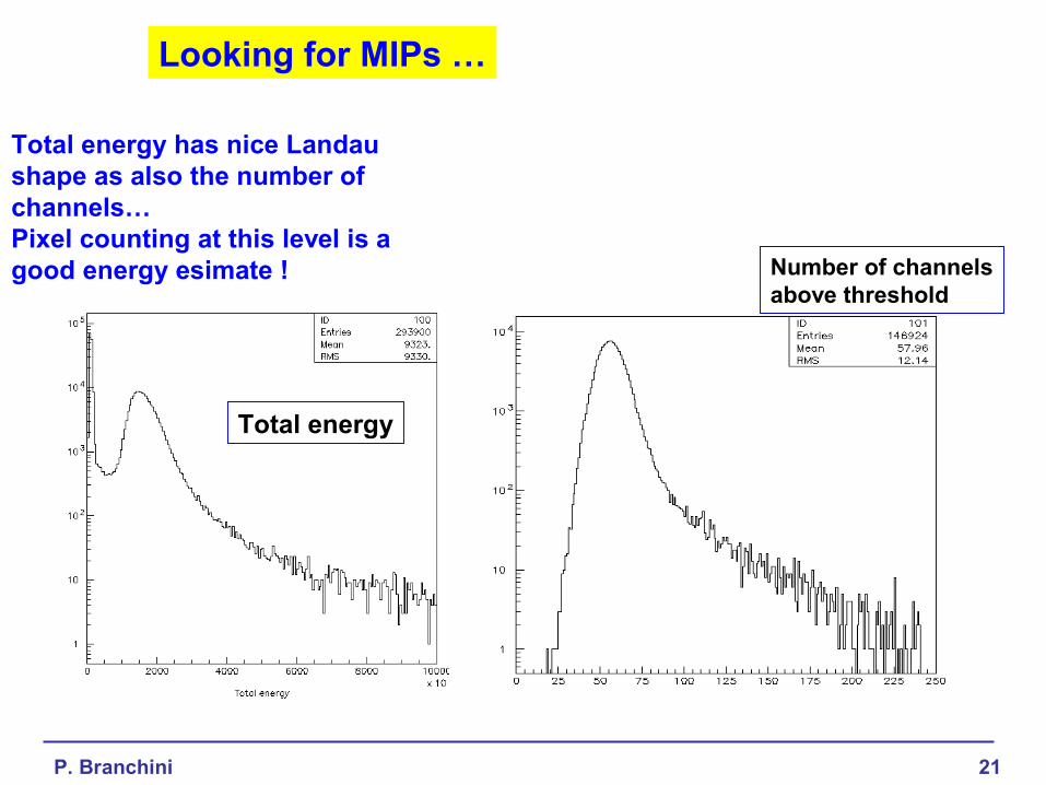
Looking for MIPs …
Total energy
Number of channelsabove threshold
Total energy has nice Landau shape as also the number of channels…Pixel counting at this level is agood energy esimate !
P. Branchini 22
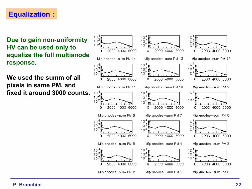
Equalization :
Due to gain non-uniformityHV can be used only toequalize the full multianoderesponse.
We used the summ of allpixels in same PM, andfixed it around 3000 counts.

P. Branchini 23
cm
Fitted track and residual distribution
A DC A .U .
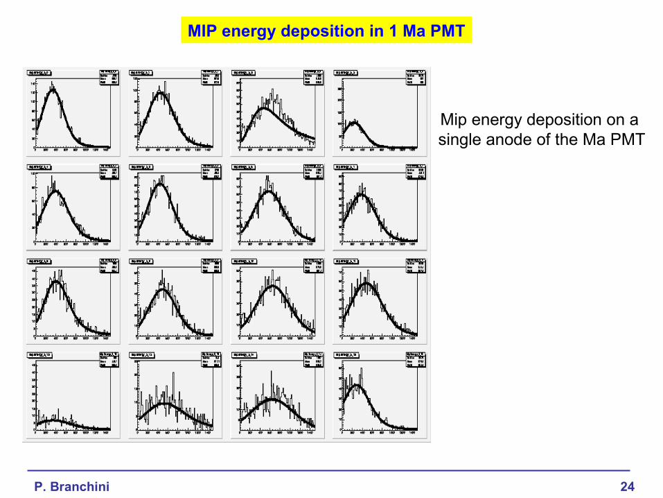
The MIP energy distribution isclearly visible also on single anode
P. Branchini 24
MIP energy deposition in 1 Ma PMT
Mip energy deposition on a single anode of the Ma PMT
P. Branchini 25
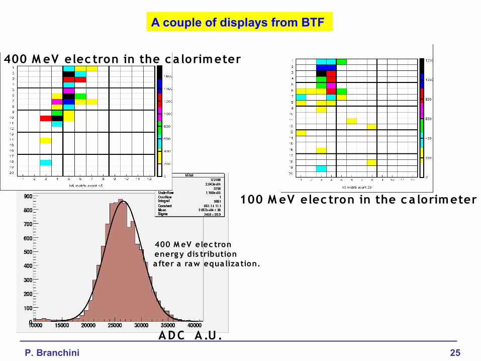
A couple of displays from BTF
400 M eV elec tron in the c a lorimeter
100 M eV elec tron in the c a lorimeter
ADC A .U .
400 M eV elec tron energ y dis tribution a fter a raw equa liza tion.

P. Branchini 26
Electron energy reconstruction and resolution
Single and double 100 MeV electron impingingthe calorimeter
ADC vs beam energy
Adc = 68*energy(MeV)+569
Resolution vs beam energy
Beam energy (MeV)
res = 0.06/sqrt(energy(GeV))+0.03

P. Branchini 27
Conclusions
A fine granularity calorimeter prototype has been realizedusing a KLOE calorimeter piece with segmented light guides andHamamatsu multianode PMs.
The response of individual channels has been studied with a laser pulseand the cross talk measured. Optical cross talk is negligible.
A full system is now operating. Many cosmics rays have been acquired and are being analyzed.
A test beam with electron at BTF is now over and data are being analysed