a r wireless power transfer in free s … 03, number 02/1-doi 10.5455-jjcit.71... · the benefits...
TRANSCRIPT

71
.Jordanian Journal of Computers and Information Technology (JJCIT), Vol. 3, No. 2, August 2017
R. Alrawashdeh is with Electrical Engineering Department, Mutah University, Alkarak, Jordan. Email: [email protected].
A REVIEW ON WIRELESS POWER TRANSFER IN FREE
SPACE AND CONDUCTING LOSSY MEDIA
Rula Alrawashdeh
(Received: 29-Dec.-2016, Revised: 08-Mar.-2017, Accepted: 02-Apr.-2017)
ABSTRACT
Recently, the interest in wireless power transfer (WPT) has significantly increased due to its attractive
applications. The power transfer efficiency and communication range of most of the existing WPT systems are
still limited, which is due to many technical challenges and regulation limitations. This requires more research
and technical efforts to overcome the current limitations and make WPT systems much more efficient and widely
used. This paper aims at reviewing recent advances and research progress in the area of WPT for the purposes
of addressing current challenges and future research directions. To obtain these purposes, an introduction to
WPT is provided. Also, main research themes of WPT in free space and lossy media are discussed. Additionally,
the benefits of using split ring resonators WPT in conducting lossy media are investigated. This will be very
helpful to boost WPT in lossy media and inspire more optimized structures for further improvement.
KEYWORDS
ICPT, MPT, PTE, UWICPT, WPT.
1. INTRODUCTION
Wireless power transfer (WPT) is a process of transferring electrical energy from transmitter to
receiver ends without wires. It can be applied to power and charge different devices, such as mobile
phones. Such applications will be very beneficial to increase the life time of devices and save their
internal space which is mainly occupied by batteries. Additionally, WPT is green for the environment,
as no batteries may be used [1]. The principle of WPT has been introduced since the days of Nikola
Tesla and WPT has been adopted for commercial use for some small items, such as phones,
toothbrushes and cochlear implants [2]-[4]. However, power transfer efficiency and range for most of
commercial systems are still limited. Due to the promising applications of WPT in different media,
research is ongoing to improve the efficiency and feasibility of WPT despite its challenges.
WPT techniques fall mainly into two categories: non-radiative and radiative techniques [2]. Most of
research themes of all WPT types focus mainly on increasing power transfer efficiency and range. The
research progress in the area of WPT has been reviewed in this paper. Compared to other related
review papers, this paper elaborates the challenges of WPT in conducting lossy media, such as the
human body. Further, it summarizes the work that has been conducted in the area of WPT to
implantable and underwater devices. Additionally, it indicates the beneficial effect of using a layer
inspired by split rings around antennas in a lossy medium on the WPT process. This paper is arranged
as follows: First, an introduction to the principle and types of WPT is provided. Then, the research that
has been conducted in the areas of inductive and microwave-based WPT in free space and lossy media
(the human body and underwater devices) is reviewed and related challenges are summarized. Finally,
the beneficial effect of using a layer inspired by split ring resonators on boosting WPT in lossy media
is indicated and demonstrated by measurements.
2. TYPES AND PRINCIPLE OF OPERATION
The principle of operation and main characteristics of different types of WPT are discussed and
summarized in this section.
2.1 Non-Radiative WPT
In non-radiative techniques, power is transferred by the following methods:

72
"A Review on Wireless Power Transfer in Free Space and Conducting Lossy Media", Rula Alrawashdeh.
2.1.1 Inductive Coupling Power Transfer (ICPT)
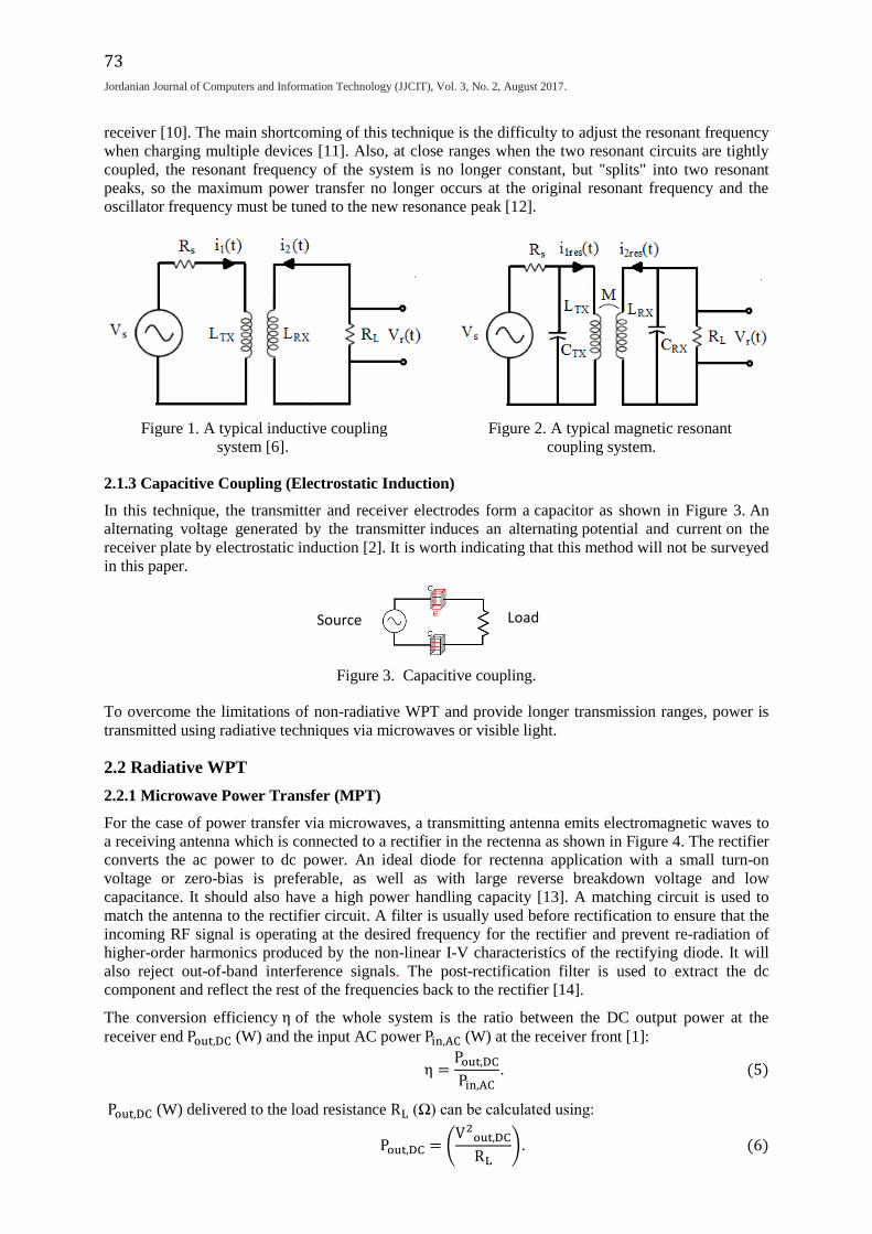
A typical inductive coupling system is shown in Figure 1. It is composed of transmitter and receiver
coils (TC and RC, respectively) of self-inductances of LTX and LRX (H), respectively. The TC is
connected to an AC source of Vs (V) voltage and Rs (Ω) internal resistance and the RC is connected to
a load resistance RL (Ω). A current i1(t) = I1 sin (ωt) passing through the primary coil produces a
magnetic field as explained by Ampere's law given in Equation (1). Most of this magnetic field links
the secondary coil which induces a voltage and current as explained by Faraday's law given in
Equation (2). Hence, power can be delivered to the load.
∮ H . dL = i . (1)
H (A/m) is the magnetic field intensity and dL (m) is a differential length element along the closed
path that encloses the current i (A) [5].
emf = −NdΦ
dt . (2)
emf (V) is the electromotive force (induced voltage), N is the number of turns of the secondary coil
and Φ (Wb) is the magnetic flux [5].
The flux linkage between coils is proportional to the current i1(t)and mutual inductance between coils
(M); Φ = M i1(t). Hence, the voltage at the receiver terminals Vr(t) (V) can be expressed as [6]:
Vr(t) = Mdi1(t)
dt≡ M ωI1 cos(ωt). (3)
This technique offers the advantages of simplicity and safety. Also, energy is stored in the region
between coils and no radiation will be lost to the surrounding area. Therefore, it has been widely used
in different applications, such as charging medical implants. However, this technique has the
shortcomings of short transmission range and sensitivity to misalignment between transmitter and
receiver coils. Additionally, strong electromagnetic fields can be harmful to the human health.
Therefore, it is important to evaluate the resonant system for WPT applications where humans are
exposed to electromagnetic fields to ensure that the safety levels enacted by the European Union [7]
are satisfied. If the distance between coils increases, the induced voltage at the receiver decreases. To
increase the power transmission efficiency (PTE) over a longer distance, resonant circuits are used as
will be discussed in the following section.
2.1.2 Magnetic Resonant Coupling (Electrodynamic Induction)
A typical magnetic resonant coupling system is shown in Figure 2. It is composed of transmitter and
receiver coils and capacitors. For simplicity, the self-inductance for each coil is supposed to be (L (H))
and the capacitance of each capacitor is (C (F)). Maximum power transfer occurs at the resonant
frequency to which the resonant circuits in the transmitter and receiver are tuned. If the distance
between coils increases, the mutual coupling between coils decreases and thus Vr(t) decreases
accordingly (see Equation (4)). The frequency or TC current can be increased to compensate for any
reduction in the induced voltage [6], [8]. However, the current in the transmitter coil is usually utilized
to increase Vr(t) as electromagnetic radiation and hence power dissipation around the system is
possibly generated at very high frequency [6]. When a resonant frequency of ωres = 1/√LC is
approached, the currents in coils grow to the huge resonant currents i1res(t) and i2res(t) (A) at the
transmitter and receiver coils, respectively. These currents produce a noticeable voltage at the receiver
(Vr(t)) and hence enough power can be delivered to a proper load [6]:
Vr(t) = Mdi1res(t)
dt+ L
di2res(t)
dt . (4)
Another effective parameter of the magnetic resonant power transfer system is the quality factor (Q-
factor), which is a measure of the ratio between the energy stored by L and C and the energy loss rate
(the loss is represented by R in the circuit) [9]. In general, resonators of high Q-factors are required for
an efficient power transfer at small coupling levels and longer distance between the transmitter and
73
.Jordanian Journal of Computers and Information Technology (JJCIT), Vol. 3, No. 2, August 2017
receiver [10]. The main shortcoming of this technique is the difficulty to adjust the resonant frequency
when charging multiple devices [11]. Also, at close ranges when the two resonant circuits are tightly
coupled, the resonant frequency of the system is no longer constant, but "splits" into two resonant
peaks, so the maximum power transfer no longer occurs at the original resonant frequency and the
oscillator frequency must be tuned to the new resonance peak [12].
Figure 1. A typical inductive coupling Figure 2. A typical magnetic resonant
system [6]. coupling system.
2.1.3 Capacitive Coupling (Electrostatic Induction)
In this technique, the transmitter and receiver electrodes form a capacitor as shown in Figure 3. An
alternating voltage generated by the transmitter induces an alternating potential and current on the
receiver plate by electrostatic induction [2]. It is worth indicating that this method will not be surveyed
in this paper.
Figure 3. Capacitive coupling.
To overcome the limitations of non-radiative WPT and provide longer transmission ranges, power is
transmitted using radiative techniques via microwaves or visible light.
2.2 Radiative WPT
2.2.1 Microwave Power Transfer (MPT)
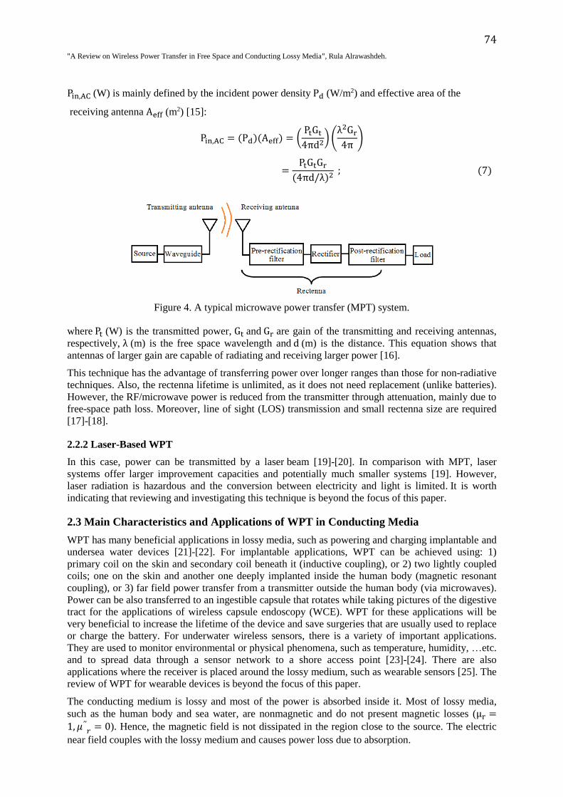
For the case of power transfer via microwaves, a transmitting antenna emits electromagnetic waves to
a receiving antenna which is connected to a rectifier in the rectenna as shown in Figure 4. The rectifier
converts the ac power to dc power. An ideal diode for rectenna application with a small turn-on
voltage or zero-bias is preferable, as well as with large reverse breakdown voltage and low
capacitance. It should also have a high power handling capacity [13]. A matching circuit is used to
match the antenna to the rectifier circuit. A filter is usually used before rectification to ensure that the
incoming RF signal is operating at the desired frequency for the rectifier and prevent re-radiation of
higher-order harmonics produced by the non-linear I-V characteristics of the rectifying diode. It will
also reject out-of-band interference signals. The post-rectification filter is used to extract the dc
component and reflect the rest of the frequencies back to the rectifier [14].
The conversion efficiency η of the whole system is the ratio between the DC output power at the
receiver end Pout,DC (W) and the input AC power Pin,AC (W) at the receiver front [1]:
η =Pout,DC
Pin,AC. (5)
Pout,DC (W) delivered to the load resistance RL (Ω) can be calculated using:
Pout,DC = (V2
out,DC
RL). (6)
Source Load
74
"A Review on Wireless Power Transfer in Free Space and Conducting Lossy Media", Rula Alrawashdeh.
Pin,AC (W) is mainly defined by the incident power density Pd (W/m2) and effective area of the
receiving antenna Aeff (m2) [15]:
Pin,AC = (Pd)(Aeff) = (PtGt
4πd2)(
λ2Gr
4π)
=PtGtGr
(4πd/λ)2 ; (7)
Figure 4. A typical microwave power transfer (MPT) system.
where Pt (W) is the transmitted power, Gt and Gr are gain of the transmitting and receiving antennas,
respectively, λ (m) is the free space wavelength and d (m) is the distance. This equation shows that
antennas of larger gain are capable of radiating and receiving larger power [16].
This technique has the advantage of transferring power over longer ranges than those for non-radiative
techniques. Also, the rectenna lifetime is unlimited, as it does not need replacement (unlike batteries).
However, the RF/microwave power is reduced from the transmitter through attenuation, mainly due to
free-space path loss. Moreover, line of sight (LOS) transmission and small rectenna size are required
[17]-[18].
2.2.2 Laser-Based WPT
In this case, power can be transmitted by a laser beam [19]-[20]. In comparison with MPT, laser
systems offer larger improvement capacities and potentially much smaller systems [19]. However,
laser radiation is hazardous and the conversion between electricity and light is limited. It is worth
indicating that reviewing and investigating this technique is beyond the focus of this paper.
2.3 Main Characteristics and Applications of WPT in Conducting Media
WPT has many beneficial applications in lossy media, such as powering and charging implantable and
undersea water devices [21]-[22]. For implantable applications, WPT can be achieved using: 1)
primary coil on the skin and secondary coil beneath it (inductive coupling), or 2) two lightly coupled
coils; one on the skin and another one deeply implanted inside the human body (magnetic resonant
coupling), or 3) far field power transfer from a transmitter outside the human body (via microwaves).
Power can be also transferred to an ingestible capsule that rotates while taking pictures of the digestive
tract for the applications of wireless capsule endoscopy (WCE). WPT for these applications will be
very beneficial to increase the lifetime of the device and save surgeries that are usually used to replace
or charge the battery. For underwater wireless sensors, there is a variety of important applications.
They are used to monitor environmental or physical phenomena, such as temperature, humidity, …etc.
and to spread data through a sensor network to a shore access point [23]-[24]. There are also
applications where the receiver is placed around the lossy medium, such as wearable sensors [25]. The
review of WPT for wearable devices is beyond the focus of this paper.
The conducting medium is lossy and most of the power is absorbed inside it. Most of lossy media,
such as the human body and sea water, are nonmagnetic and do not present magnetic losses (μr =1, 𝜇′′
𝑟 = 0). Hence, the magnetic field is not dissipated in the region close to the source. The electric
near field couples with the lossy medium and causes power loss due to absorption.
75
.Jordanian Journal of Computers and Information Technology (JJCIT), Vol. 3, No. 2, August 2017
The absorbed power (Pabs) increases with the magnitude of the electric near field intensity (|E|) [26]:
Pabs = ω
2∭ε0ε
′′r|E|2dV; (8)
where ω (rad/s) is the angular frequency, ε0 (F/m) is the free space permittivity and εr′′ is related to the
imaginary part of the tissue permittivity which accounts for the electric losses of the medium [26]-
[27].
𝜀 = 𝜀0(𝜀′𝑟 − 𝑗𝜀 ′′𝑟). (9)
Conductivity and permittivity of these lossy media are frequency -and temperature- dependent. The
main challenge in all these applications is to mitigate the negative effect of the lossy medium on the
power transfer system as much as possible. Requirements of the inductive coupling WPT for
implantable applications in the lossy human body can be summarized as follows:
1. Small coil dimensions that fit into the available space inside the small implantable device.
2. Large inductance and quality factor Q over the frequency range of interest given the limited
available space and size. This represents a challenge as an implantable coil of small size has
usually a small inductance [28].
3. Robust performance with the other internal components of the implant (the performance should
not be altered with the overall device package).
4. Robustness against misalignments.
5. Satisfaction of safety limitations.
Some of these requirements are contradictory as indicated in point 2. Thus, design parameters should
be carefully adjusted to obtain the largest possible inductive coupling for a compact size. The
probability of misalignment to happen is high for this case because of the changing and time-variant
human body environment. For the case of underwater sea applications, size and safety requirements
are less restricted. For the case of MPT for implants, antennas of magnetic type, such as loop antennas
are preferred, because non-magnetic lossy media do not present magnetic losses. It is very important
to satisfy the safety limitations of the specific absorption rate (SAR) and current density in order not to
heat up the human body tissues [29]-[30]. The SAR can be calculated using Equation (10); where σ
(S/m) and ρ (kg/m3) are the tissue conductivity and mass density, respectively, and |E| is the
magnitude of electric near field intensity. Excessive received power may cause overheating of the
receiver coil, but according to the Japan Society of Medical Electronics and Biological Engineering
(JSMEBE), temperatures below 42.5 °C are safe for the tissues surrounding the RC [31].
SAR =σ|E|2
ρ. (10)
3. RESEARCH PROGRESS AND CHALLENGES
In this section, the main contributions and challenges in the area of WPT are reviewed.
3.1 Inductive WPT
3.1.1 In Free Space
Many WPT systems based on inductive coupling were presented in literature for both of low (mill
watts) and high power (multiple kilowatts) applications, such as charging mobile phones and
powering electric vehicles, respectively [32]-[33]. A PTE of more than 75% was obtained for these
systems at a distance of less than 10 cm between the transmit and receive coils [34]. A mobile phone
charger was developed in [32] at 1.2 MHz. For this system, an output DC voltage of 3.79 V was
obtained at the load when the distance between the TC and RC was 5 cm. An inductive coupling
system was also proposed in [35] for a radio frequency identification (RFID) system. However, PTE
decreases with distance and when misalignment happens. Moreover, the receiver mobility is very
restricted. Research has been directed to overcome these shortcomings as summarized in Table 1.
76
"A Review on Wireless Power Transfer in Free Space and Conducting Lossy Media", Rula Alrawashdeh.
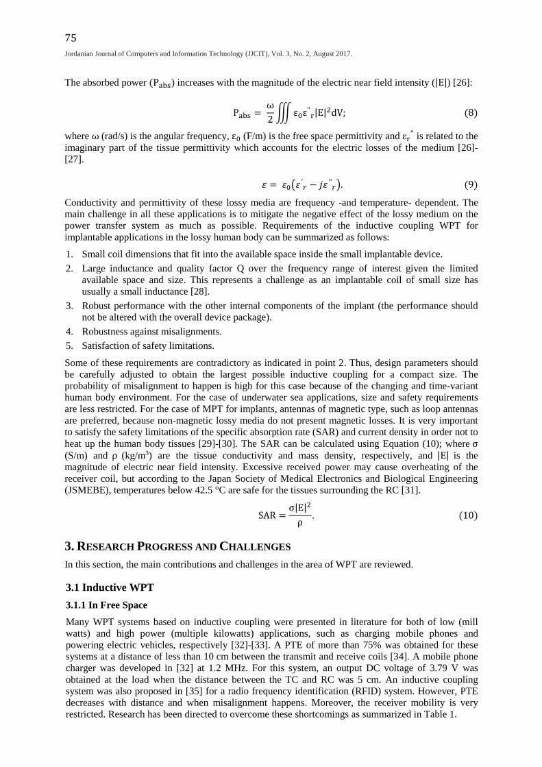
(a) (b) (c)
Figure 5. Proposed designs of multiple coils and resonators in: (a) [36], (b) [37] and (c) [38].
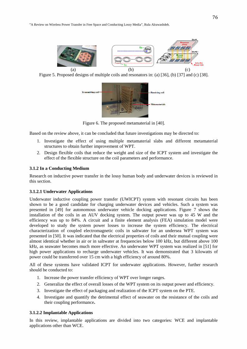
Figure 6. The proposed metamaterial in [40].
Based on the review above, it can be concluded that future investigations may be directed to:
1. Investigate the effect of using multiple metamaterial slabs and different metamaterial
structures to obtain further improvement of WPT.
2. Design flexible coils that reduce the weight and size of the ICPT system and investigate the
effect of the flexible structure on the coil parameters and performance.
3.1.2 In a Conducting Medium
Research on inductive power transfer in the lossy human body and underwater devices is reviewed in
this section.
3.1.2.1 Underwater Applications
Underwater inductive coupling power transfer (UWICPT) system with resonant circuits has been
shown to be a good candidate for charging underwater devices and vehicles. Such a system was
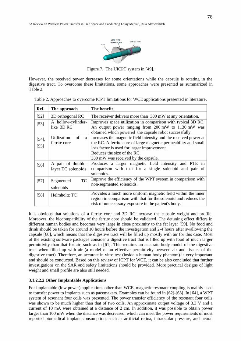
presented in [49] for autonomous underwater vehicle docking applications. Figure 7 shows the
installation of the coils in an AUV docking system. The output power was up to 45 W and the
efficiency was up to 84%. A circuit and a finite element analysis (FEA) simulation model were
developed to study the system power losses to increase the system efficiency. The electrical
characterization of coupled electromagnetic coils in saltwater for an undersea WPT system was
presented in [50]. It was indicated that the electrical properties of coils and their mutual coupling were
almost identical whether in air or in saltwater at frequencies below 100 kHz, but different above 100
kHz, as seawater becomes much more effective. An underwater WPT system was realized in [51] for
high power applications to recharge underwater vehicles. It was demonstrated that 3 kilowatts of
power could be transferred over 15 cm with a high efficiency of around 80%.
All of these systems have validated ICPT for underwater applications. However, further research
should be conducted to:
1. Increase the power transfer efficiency of WPT over longer ranges.
2. Generalize the effect of overall losses of the WPT system on its output power and efficiency.
3. Investigate the effect of packaging and realization of the ICPT system on the PTE.
4. Investigate and quantify the detrimental effect of seawater on the resistance of the coils and
their coupling performance.
3.1.2.2 Implantable Applications
In this review, implantable applications are divided into two categories: WCE and implantable
applications other than WCE.

77
.Jordanian Journal of Computers and Information Technology (JJCIT), Vol. 3, No. 2, August 2017
3.1.2.2.1 WCE Applications
Magnetic resonant WPT is mainly used for this case, as the distance between TC and RC is relatively
long. Low power levels are usually required to power or charge wireless capsules.
Table 1. A summary of main design approaches for inductive WPT in free space in literature.
Facility of improvement: Multiple coils. See Figure 5. Ref. and proposed approach [36] Multiple overlapped transmitter coils
Achievements Mitigation of misalignment.
Multiple receiver coils can be powered at the same time.
Shortcomings Increase of design size and complexity as a control IC is used to
detect which coil is the best for WPT.
Ref. and proposed approach [37] Array of coils of similar resonant frequency
Achievements Increase of mobility range of the receiver.
Increase of power transfer range.
Multiple receiver coils can be powered at the same time.
PTE of around 85% at f= 25 MHz for 10 resonant loops.
Shortcomings Increase of design size and complexity.
Ref. and proposed approach [38] Planar spiral coils are designed using a 0.13µm
CMOS process and vertically stacked.
Achievements Increase of the amount of the transferred power which depends on
the coil's diameter and distance between coils. PTE of 52% for a
power transfer density of 49 mW/mm2.
Shortcomings Increase of design size.
Facility of improvement: Metamaterials. See Figure 6.
Ref. and proposed approach [39] An NIM slab used between two resonators
Achievements Improvement of magnetic coupling and hence power transfer
efficiency due to enhancement of the evanescent wave coupling.
PTE of around 50% at f= 10 MHz.
Shortcomings Complicated to design and fabricate, because both of 𝜀 and µ are
required to be negative.
Large loss, as it responses to both of electric and magnetic fields.
Ref. and proposed approach [40], [41] A single negative ( μ = −1 ) metamaterial slab
between resonators.
Achievements Increases PTE with smaller losses and complexity in comparison
with those of the NIM slab.
[40] PTE of 50% at f= 27.12 MHz which is 42% larger than that
when no metamaterial slab is used.
[41] PTE of 18.2% at f= 26.65 MHz which is 61% larger than that
when no metamaterial slab is used.
Shortcomings Larger losses than those when no slab is used.
Facility of improvement: Techniques for mitigating frequency splitting.
Ref. and proposed approach [42], [43], [44], [45], [46] Frequency tracking/ tuning
techniques.
Achievements The driving frequency of the ICPT link is maintained at an
optimum value to ensure that the link is working at resonance and
the output voltage is maximized.
[42] PTE of over 70% for a range of 0-70 cm.
[46] PTE of 15% at f= 4.5-5.5 MHz.
Shortcomings Additional space and power consumption are introduced because a
series of complex control circuits -such as phase compensator
phase-locked loop- is required.
Ref. and proposed approach [47], [48] Anti-parallel resonant loops,
Non-identical resonant coils (NIRCs)
Achievements Offset of excess mutual inductance (magnetic over coupling)
which is the reason of frequency splitting.
Shortcomings Further investigations on the system stability and impact of coil
parameters on the overall system performance are required.
78
"A Review on Wireless Power Transfer in Free Space and Conducting Lossy Media", Rula Alrawashdeh.
Figure 7. The UICPT system in [49].
However, the received power decreases for some orientations while the capsule is rotating in the
digestive tract. To overcome these limitations, some approaches were presented as summarized in
Table 2.
Table 2. Approaches to overcome ICPT limitations for WCE applications presented in literature.
Ref. The approach The benefit
[52] 3D orthogonal RC The receiver delivers more than 300 mW at any orientation.
[53] A hollow-cylinder-
like 3D RC Improves space utilization in comparison with typical 3D RC. An output power ranging from 206 mW to 1130 mW was
obtained which powered the capsule robot successfully.
[54],
[55]
Utilization of a
ferrite core
Increases the magnetic field intensity and the received power at
the RC. A ferrite core of large magnetic permeability and small
loss factor is used for larger improvement.
Reduces the size of the RC.
330 mW was received by the capsule.
[56] A pair of double-
layer TC solenoids Produces a larger magnetic field intensity and PTE in
comparison with that for a single solenoid and pair of
solenoids.
[57] Segmented TC
solenoids
Improve the efficiency of the WPT system in comparison with
non-segmented solenoids.
[58] Helmholtz TC Provides a much more uniform magnetic field within the inner
region in comparison with that for the solenoid and reduces the
risk of unnecessary exposure in the patient's body.
It is obvious that solutions of a ferrite core and 3D RC increase the capsule weight and profile.
Moreover, the biocompatibility of the ferrite core should be validated. The detuning effect differs in
different human bodies and becomes very large in close proximity to the fat layer [59]. No food and
drink should be taken for around 10 hours before the investigation and 2-4 hours after swallowing the
capsule [60], which means that the digestive tract will be filled up mostly with air for this case. Most
of the existing software packages consider a digestive tract that is filled up with food of much larger
permittivity than that for air, such as in [61]. This requires an accurate body model of the digestive
tract when filled up with air (a model of an effective permittivity between air and tissues of the
digestive tract). Therefore, an accurate in vitro test (inside a human body phantom) is very important
and should be conducted. Based on this review of ICPT for WCE, it can be also concluded that further
investigations on the SAR and safety limitations should be provided. More practical designs of light
weight and small profile are also still needed.
3.1.2.2.2 Other Implantable Applications
For implantable (low power) applications other than WCE, magnetic resonant coupling is mainly used
to transfer power to implants such as pacemakers. Examples can be found in [62]-[63]. In [64], a WPT
system of resonant four coils was presented. The power transfer efficiency of the resonant four coils
was shown to be much higher than that of two coils. An approximate output voltage of 3.3 V and a
current of 10 mA were obtained at a distance of 2 cm. In addition, it was possible to obtain power
larger than 100 mW when the distance was decreased, which can meet the power requirements of most
reported biomedical implant consumption, such as artificial retina, intraocular pressure, and neural

79
.Jordanian Journal of Computers and Information Technology (JJCIT), Vol. 3, No. 2, August 2017
recording system. Printed coils for magnetic resonant coupling were designed in [26], [65]. In [65], a
procedure to design the geometries of a pair of lithographically planar printed spiral coils was
presented. This procedure optimized the mutual inductance and quality factor of printed coils in a way
that the PTE was maximized. A flexible coil design was also presented in [66]. The transmitter and
receiver coils were realized by inkjet printing. Wireless power transfer efficiencies of 55% and 35% at
13.56 MHz were obtained for the air and water (for testing purposes) surrounding environments,
respectively. The printed and flexible designs help in providing more conformity and reducing the
device size, weight and profile. However, further studies are still needed to: characterize the effect of
the lossy human body on the design parameters and performance of printed or flexible coils, derive
formulae of the design parameters for different structures of printed or flexible coils and evaluate the
performance of flexible coils when they get bent.
3.2 Microwave-Based Systems
3.2.1 In Free Space
Research in this area has been mainly focused on optimizing the design of the receiving antenna and
rectifier circuit. For the rectifier circuit, different rectifier diodes were used. Examples can be found
in [67] and [68], where (HSMS-8101) and (HSMS2860) Schottky diodes were used, respectively
because of their high speed and low voltage drop. A novel wide dynamic range and high-efficiency
rectifier was proposed in [69]. The proposed rectifier consisted of two rectifying circuits in parallel,
an asymmetrical output impedance power divider which adaptively divided the RF input signal to the
rectifying circuits according to a signal power level and a DC combiner. More than 27 dB dynamic
range with an RF-DC conversion efficiency of higher than 50% was obtained. A maximum
conversion efficiency of 76.8% at 2.45 GHz was obtained at an input power of 5dBm. In [70],
metasurfaces composed of different types of resonators were used instead of antennas in the rectenna,
as they were found to be more efficient than classical antennas in energy harvesting. However, no in-
depth study has been provided to explain the overall benefits of metasurfaces for the WPT process in
general (not for harvesting purposes only). Antenna optimization techniques proposed in literature
are summarized in Table 3. Metamaterials and metamaterial-based structures are found to be very
advantageous for ICPT. Therefore, it is important to investigate them for MPT in depth.
3.2.2 In a Lossy Medium
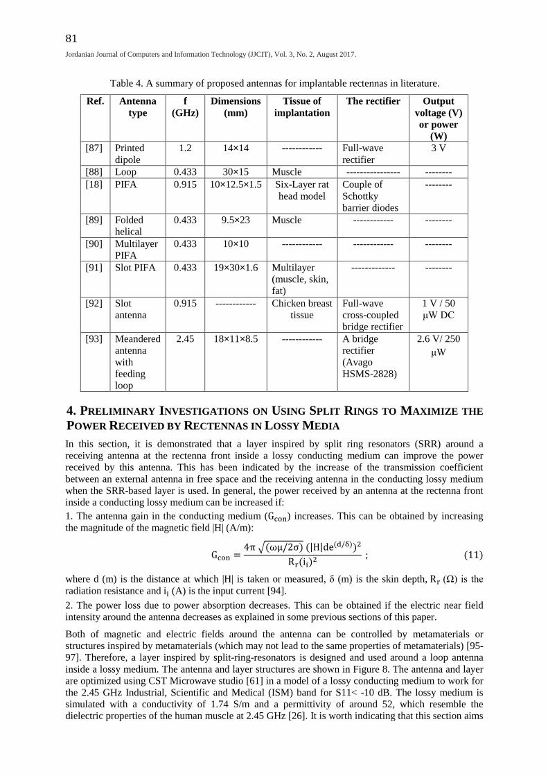
For implantable rectennas, different types of antenna were designed and presented as summarized in
Table 4. It is worth indicating that the comparison between different implantable rectennas can be
considered accurate only if the properties of the medium of implantation is the same for all of them.
Magnetic type antennas, such as loop antennas, are popular for this type of application, because they
are of smaller SAR and larger radiation efficiency and gain. PIFAs have the advantages of small size
and low profile in addition to relatively small electric near field and SAR. 0.433 GHz is mainly
exploited for the applications of implantable rectennas, because it enables size reduction of the
rectenna system in comparison with that at lower frequencies. At the same time, the human body loss
around this frequency is smaller than that at higher frequencies. For the rectifier design, it is preferred
to facilitate low turn-on voltage and very low leakage current. Different rectifier designs in literature
are summarized in Table 4.
It is very important to evaluate and validate the implantable rectenna performance with the overall
package which may alter the overall antenna performance. This has been done in some research
studies such as in [93]. However, further deep related investigations are still needed. Based on this
survey of proposed designs in literature, future research should be focused on:
1. Introducing new techniques and designs that further increase the magnetic field or decrease
the electric field in close proximity to the implantable antenna, in order to boost the power
received at the rectenna.
2. Introducing new techniques to maintain matching (of the receiving antenna and between the
receiving antenna and rectifier) in the time-variant human body.
3. Investigating the effect of the implantable device packaging on the WPT process.
4. Validating the WPT system by both of in-vitro and in-vivo tests.
80
"A Review on Wireless Power Transfer in Free Space and Conducting Lossy Media", Rula Alrawashdeh.
5. Evaluating the WPT system using actual design parameters (load resistance, available diodes,
…etc.) for actual implantable chips in the market.
6. Characterizing the WPT channel of the human body in different areas of implantation for
different implantable applications.
7. Investigating metamaterials or structures inspired by metamaterials for MPT in lossy media.
The benefits of these structures will be indicated in the following section.
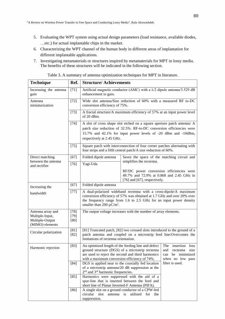
Table 3. A summary of antenna optimization techniques for MPT in literature.
Technique Ref. Structure/ Achievements
Increasing the antenna
gain
[71] Artificial magnetic conductor (AMC) with a λ/2 dipole antenna/3.529 dB
enhancement in gain.
Antenna
miniaturization
[72] Wide slot antenna/Size reduction of 60% with a measured RF to-DC
conversion efficiency of 75%.
[73] A fractal structure/A maximum efficiency of 57% at an input power level
of 20 dBm.
[74] A slot of cross shape slot etched on a square aperture patch antenna/ A
patch size reduction of 32.5%. RF-to-DC conversion efficiencies were
15.7% and 42.1% for input power levels of -20 dBm and -10dBm,
respectively at 2.45 GHz.
[75] Square patch with interconnection of four corner patches alternating with
four strips and a fifth central patch/A size reduction of 60%.
Direct matching
between the antenna
and rectifier
[67] Folded dipole antenna Saves the space of the matching circuit and
simplifies the rectenna.
RF/DC power conversion efficiencies were
49.7% and 72.9% at 0.868 and 2.45 GHz in
[76] and [67], respectively.
[76] Yagi-Uda
Increasing the
bandwidth
[67] Folded dipole antenna
[77] A dual-polarized wideband rectenna with a cross-dipole/A maximum
conversion efficiency of 57% was obtained at 1.7 GHz and over 20% over
the frequency range from 1.6 to 2.5 GHz for an input power density
smaller than 200 µC/m2.
Antenna array and
Multiple-Input,
Multiple-Output
(MIMO) elements
[78]
[79]
[80]
The output voltage increases with the number of array elements.
Circular polarization [81]
[82]
[81] Truncated patch, [82] two crossed slots introduced to the ground of a
patch antenna and coupled on a microstrip feed line/Overcomes the
limitations of rectenna orientation.
Harmonic rejection [83] An optimized length of the feeding line and defect
ground structure (DGS) of a microstrip rectenna
are used to reject the second and third harmonics
with a maximum conversion efficiency of 74%.
The insertion loss
and rectenna size
can be minimized
when no low pass
filter is used. [84] DGS is applied near to the coaxially fed location
of a microstrip antenna/20 dB suppression at the
2nd and 3rd harmonic frequencies.
[85] Harmonics were suppressed with the aid of a
spur-line that is inserted between the feed and
short line of Planar Inverted-F Antenna (PIFA).
[86] A single slot on a ground conductor of a CPW-fed
circular slot antenna is utilized for the
suppression.
81
.Jordanian Journal of Computers and Information Technology (JJCIT), Vol. 3, No. 2, August 2017
Table 4. A summary of proposed antennas for implantable rectennas in literature.
Ref. Antenna
type
f
(GHz)
Dimensions
(mm)
Tissue of
implantation
The rectifier Output
voltage (V)
or power
(W) [87] Printed
dipole
1.2 14×14 ------------ Full-wave
rectifier
3 V
[88] Loop 0.433 30×15 Muscle ---------------- --------
[18] PIFA 0.915 10×12.5×1.5 Six-Layer rat
head model
Couple of
Schottky
barrier diodes
--------
[89] Folded
helical
0.433 9.5×23 Muscle ------------ --------
[90] Multilayer
PIFA
0.433 10×10 ------------ ------------ --------
[91] Slot PIFA 0.433 19×30×1.6 Multilayer
(muscle, skin,
fat)
------------- --------
[92] Slot
antenna
0.915 ------------ Chicken breast
tissue
Full-wave
cross-coupled
bridge rectifier
1 V / 50
μW DC
[93] Meandered
antenna
with
feeding
loop
2.45 18×11×8.5 ------------ A bridge
rectifier
(Avago
HSMS-2828)
2.6 V/ 250
μW
4. PRELIMINARY INVESTIGATIONS ON USING SPLIT RINGS TO MAXIMIZE THE
POWER RECEIVED BY RECTENNAS IN LOSSY MEDIA
In this section, it is demonstrated that a layer inspired by split ring resonators (SRR) around a
receiving antenna at the rectenna front inside a lossy conducting medium can improve the power
received by this antenna. This has been indicated by the increase of the transmission coefficient
between an external antenna in free space and the receiving antenna in the conducting lossy medium
when the SRR-based layer is used. In general, the power received by an antenna at the rectenna front
inside a conducting lossy medium can be increased if:
1. The antenna gain in the conducting medium (Gcon) increases. This can be obtained by increasing
the magnitude of the magnetic field |H| (A/m):
Gcon =4π √(ωμ/2σ) (|H|de(d/δ))2
Rr(ii)2
; (11)
where d (m) is the distance at which |H| is taken or measured, δ (m) is the skin depth, Rr (Ω) is the
radiation resistance and ii (A) is the input current [94].
2. The power loss due to power absorption decreases. This can be obtained if the electric near field
intensity around the antenna decreases as explained in some previous sections of this paper.
Both of magnetic and electric fields around the antenna can be controlled by metamaterials or
structures inspired by metamaterials (which may not lead to the same properties of metamaterials) [95-
97]. Therefore, a layer inspired by split-ring-resonators is designed and used around a loop antenna
inside a lossy medium. The antenna and layer structures are shown in Figure 8. The antenna and layer
are optimized using CST Microwave studio [61] in a model of a lossy conducting medium to work for
the 2.45 GHz Industrial, Scientific and Medical (ISM) band for S11< -10 dB. The lossy medium is
simulated with a conductivity of 1.74 S/m and a permittivity of around 52, which resemble the
dielectric properties of the human muscle at 2.45 GHz [26]. It is worth indicating that this section aims
82
"A Review on Wireless Power Transfer in Free Space and Conducting Lossy Media", Rula Alrawashdeh.
to show the advantages of using SRR layer for WPT in lossy media and not to optimize the design for
maximum power transfer.
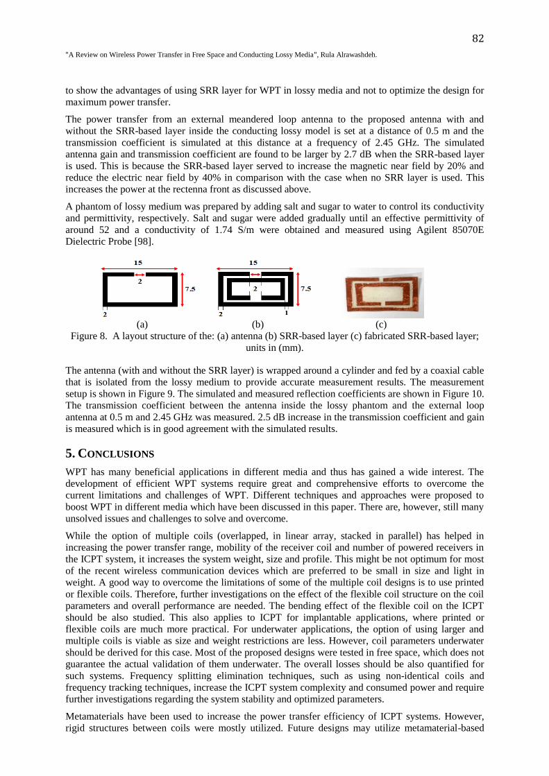
The power transfer from an external meandered loop antenna to the proposed antenna with and
without the SRR-based layer inside the conducting lossy model is set at a distance of 0.5 m and the
transmission coefficient is simulated at this distance at a frequency of 2.45 GHz. The simulated
antenna gain and transmission coefficient are found to be larger by 2.7 dB when the SRR-based layer
is used. This is because the SRR-based layer served to increase the magnetic near field by 20% and
reduce the electric near field by 40% in comparison with the case when no SRR layer is used. This
increases the power at the rectenna front as discussed above.
A phantom of lossy medium was prepared by adding salt and sugar to water to control its conductivity
and permittivity, respectively. Salt and sugar were added gradually until an effective permittivity of
around 52 and a conductivity of 1.74 S/m were obtained and measured using Agilent 85070E
Dielectric Probe [98].
(a) (b) (c)
Figure 8. A layout structure of the: (a) antenna (b) SRR-based layer (c) fabricated SRR-based layer;
units in (mm).
The antenna (with and without the SRR layer) is wrapped around a cylinder and fed by a coaxial cable
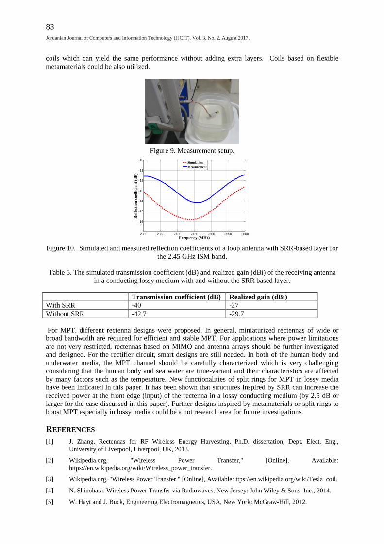
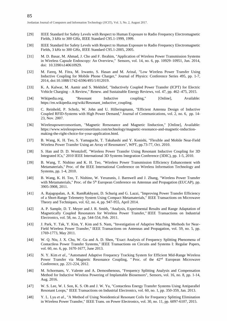
that is isolated from the lossy medium to provide accurate measurement results. The measurement
setup is shown in Figure 9. The simulated and measured reflection coefficients are shown in Figure 10.
The transmission coefficient between the antenna inside the lossy phantom and the external loop
antenna at 0.5 m and 2.45 GHz was measured. 2.5 dB increase in the transmission coefficient and gain
is measured which is in good agreement with the simulated results.
5. CONCLUSIONS
WPT has many beneficial applications in different media and thus has gained a wide interest. The
development of efficient WPT systems require great and comprehensive efforts to overcome the
current limitations and challenges of WPT. Different techniques and approaches were proposed to
boost WPT in different media which have been discussed in this paper. There are, however, still many
unsolved issues and challenges to solve and overcome.
While the option of multiple coils (overlapped, in linear array, stacked in parallel) has helped in
increasing the power transfer range, mobility of the receiver coil and number of powered receivers in
the ICPT system, it increases the system weight, size and profile. This might be not optimum for most
of the recent wireless communication devices which are preferred to be small in size and light in
weight. A good way to overcome the limitations of some of the multiple coil designs is to use printed
or flexible coils. Therefore, further investigations on the effect of the flexible coil structure on the coil
parameters and overall performance are needed. The bending effect of the flexible coil on the ICPT
should be also studied. This also applies to ICPT for implantable applications, where printed or
flexible coils are much more practical. For underwater applications, the option of using larger and
multiple coils is viable as size and weight restrictions are less. However, coil parameters underwater
should be derived for this case. Most of the proposed designs were tested in free space, which does not
guarantee the actual validation of them underwater. The overall losses should be also quantified for
such systems. Frequency splitting elimination techniques, such as using non-identical coils and
frequency tracking techniques, increase the ICPT system complexity and consumed power and require
further investigations regarding the system stability and optimized parameters.
Metamaterials have been used to increase the power transfer efficiency of ICPT systems. However,
rigid structures between coils were mostly utilized. Future designs may utilize metamaterial-based
83
.Jordanian Journal of Computers and Information Technology (JJCIT), Vol. 3, No. 2, August 2017
2300 2350 2400 2450 2500 2550 2600
-16
-15
-14
-13
-12
-11
-10
Frequency (MHz)
Refl
ecti
on
coeff
icie
nt
(dB
)
Simulation
Measurement
coils which can yield the same performance without adding extra layers. Coils based on flexible
metamaterials could be also utilized.
Figure 9. Measurement setup.
Figure 10. Simulated and measured reflection coefficients of a loop antenna with SRR-based layer for
the 2.45 GHz ISM band.
Table 5. The simulated transmission coefficient (dB) and realized gain (dBi) of the receiving antenna
in a conducting lossy medium with and without the SRR based layer.
Transmission coefficient (dB) Realized gain (dBi)
With SRR -40 -27
Without SRR -42.7 -29.7
For MPT, different rectenna designs were proposed. In general, miniaturized rectennas of wide or
broad bandwidth are required for efficient and stable MPT. For applications where power limitations
are not very restricted, rectennas based on MIMO and antenna arrays should be further investigated
and designed. For the rectifier circuit, smart designs are still needed. In both of the human body and
underwater media, the MPT channel should be carefully characterized which is very challenging
considering that the human body and sea water are time-variant and their characteristics are affected
by many factors such as the temperature. New functionalities of split rings for MPT in lossy media
have been indicated in this paper. It has been shown that structures inspired by SRR can increase the
received power at the front edge (input) of the rectenna in a lossy conducting medium (by 2.5 dB or
larger for the case discussed in this paper). Further designs inspired by metamaterials or split rings to
boost MPT especially in lossy media could be a hot research area for future investigations.
REFERENCES
[1] J. Zhang, Rectennas for RF Wireless Energy Harvesting, Ph.D. dissertation, Dept. Elect. Eng.,
University of Liverpool, Liverpool, UK, 2013.
[2] Wikipedia.org, "Wireless Power Transfer," [Online], Available:
https://en.wikipedia.org/wiki/Wireless_power_transfer.
[3] Wikipedia.org, "Wireless Power Transfer," [Online], Available: ttps://en.wikipedia.org/wiki/Tesla_coil.
[4] N. Shinohara, Wireless Power Transfer via Radiowaves, New Jersey: John Wiley & Sons, Inc., 2014.
[5] W. Hayt and J. Buck, Engineering Electromagnetics, USA, New York: McGraw-Hill, 2012.

84
"A Review on Wireless Power Transfer in Free Space and Conducting Lossy Media", Rula Alrawashdeh.
[6] H. Sugiyama, "Performance Analysis of Magnetic Resonant System Based on Electrical Circuit
Theory," in: Tech., pp. 95-116, Jan. 2012.
[7] ICNIRP Guidelines for Limiting Exposure to Time-Varying Electric, Magnetic and Electromagnetic
Fields (up to 300 GHz), Health Physics, vol. 74, no. 4, pp. 494‐522, 1998.
[8] M. A. Hassan and A. Elzawawi, "Wireless Power Transfer through Inductive Coupling," Proc. of 19th
International Conference on Circuits (part of CSCC '15), pp.115-118, 2015.
[9] D. M. Pozar, Microwave Engineering, USA, New Jersey, John Wiley & Sons, Inc., 2015.
[10] M. Kesler, "Highly Resonant Wireless Power Transfer: Safe, Efficient and over Distance," Witricity
Corporation-White Paper, pp. 1-13, 2017.
[11] X. Mou and H. Sun, "Wireless Power Transfer: Survey and Roadmap," Proc. of 81st Vehicular
Technology Conference (VTC2015- Spring), pp. 1-13, 2015.
[12] M. Biswal, P. Sharma, N. Shete, S. Sokande and P. Tayade, "Study and Survey of Wireless Charging
Technologies," International Journal of Advanced Research in Computer Engineering & Technology
(IJARCET), vol. 5, no. 5, pp. 1450–1453, May 2016.
[13] L. M. M. Tan, Efficient Rectenna Design for Wireless Power Transmission for MAV Applications,
Master thesis, Dept. Elect. and Computer Eng., Naval Postgraduate School, California, Dec. 2005.
[14] C-H. Hung, Design and Development of Wireless Power Transmission for Unmanned Air Vehicles,
Master thesis, Dept. Elect. and Computer Eng., Naval Postgraduate School, California, Sep. 2012.
[15] Antenna-theory.com, "The Friis Equation," [Online], Available: http://www.antenna-
theory.com/basics/friis.php.
[16] Y. Huang and K. Boyle, Antennas from Theory to Practice, UK, John Wiley & Sons, Ltd., 2008.
[17] R. Mehrotra, "Cut the Cord: Wireless Power Transfer, Its Applications and Its Limits," pp. 1-11. 2014,
[Online], Available: http://www.cse.wustl.edu/~jain/cse574-14/ftp/power.pdf, [Accessed: 5- May-
2014].
[18] M. K. Hosain et al., "Development of a Compact Rectenna for Wireless Powering of a Head-Mountable
Deep Brain Stimulation Device," IEEE Journal of Translational Engineering in Health and Medicine,
vol. 2, pp. 1-13, 2014.
[19] L. Summerer and O. Purcell, "Concepts for Wireless Energy Transmission via Laser," [Online],
Available: http://www.esa.int/gsp/ACT/doc/POW/ACT-RPR-NRG-2009-SPS-ICSOS-concepts-for-
laser-WPT.pdf.
[20] A. W. Bett, F. Dimroth, R. Lockenhoff, E. Oliva and J. Schubert, "III–V Solar Cells under
Monochromatic Illumination," Proc. of 33rd IEEE Photovoltaic Specialists Conference, pp. 1-5, 2008.
[21] A. Yakovlev, S. Kim and A. Poon, "Implantable Biomedical Devices: Wireless Powering and
Communication," IEEE Communications Magazine, vol. 50, no. 4, pp. 152-159, April 2012.
[22] N. W. Bergmann, J. Juergens, L. Hou, Y. Wang and J. Trevathan, "Wireless Underwater Power and
Data Transfer," Proc. of 38th Annual IEEE Conference on Local Computer Networks- Workshops, pp.
104-107, 2013.
[23] E. A. Karagianni, "Electromagnetic Waves under Sea: Bow-Tie Antenna Design for Wi-Fi Underwater
Communications, " Progress in Electromagnetics Research M, vol. 41, pp. 189–198, 2015.
[24] W. Dargie and C. Poellabauer, Fundamentals of Wireless Sensor Networks: Theory and Practice, USA,
New Jersey, John Wiley and Sons, Ltd., 2010.
[25] C. M. Nguyen et al., "Wireless Power Transfer for Autonomous Wearable Neurotransmitter Sensors,''
Sensors, vol. 15, no. 9, pp. 24553-24572, Sep. 2015, doi:10.3390/s150924553.
[26] F. Merli, Implantable Antennas for Biomedical Applications, Ph.D. dissertation, Dept. Elect. Eng.,
EPFL Univ., Lausanne, Switzerland, 2011.
[27] R. W. P. King and G. S. Smith, Antennas in Matter: Fundamentals, Theory and Applications,
Cambridge, Mass: MIT Press, 1981.
[28] Allaboutcircuits.com, "Factors Affecting Inductance," [Online], Available:
http://www.allaboutcircuits.com/textbook/direct-current/chpt-15/factors-affecting-inductance/ .
85
.Jordanian Journal of Computers and Information Technology (JJCIT), Vol. 3, No. 2, August 2017
[29] IEEE Standard for Safety Levels with Respect to Human Exposure to Radio Frequency Electromagnetic
Fields, 3 kHz to 300 GHz, IEEE Standard C95.1-1999, 1999.
[30] IEEE Standard for Safety Levels with Respect to Human Exposure to Radio Frequency Electromagnetic
Fields, 3 kHz to 300 GHz, IEEE Standard C95.1-2005, 2005.
[31] M. D. Basar, M. Ahmad, J. Cho and F. Ibrahim, "Application of Wireless Power Transmission Systems
in Wireless Capsule Endoscopy: An Overview," Sensors, vol. 14, no. 6, pp. 10929–10951, Jun. 2014,
doi: 10.3390/s140610929.
[32] M. Fareq, M. Fitra, M. Irwanto, S. Hasan and M. Arinal, "Low Wireless Power Transfer Using
Inductive Coupling for Mobile Phone Charger," Journal of Physics: Conference Series 495, pp. 1-7,
2014, doi:10.1088/1742-6596/495/1/012019.
[33] K. A. Kalwar, M. Aamir and S. Mekhilef, "Inductively Coupled Power Transfer (ICPT) for Electric
Vehicle Charging – A Review," Renew. and Sustainable Energy Reviews, vol. 47, pp. 462–475, 2015.
[34] Wikipedia.org, "Resonant Inductive coupling," [Online], Available:
https://en.wikipedia.org/wiki/Resonant_inductive_coupling.
[35] C. Reinhold, P. Scholz, W. John and U. Hilleringmann, "Efficient Antenna Design of Inductive
Coupled RFID-Systems with High Power Demand,'' Journal of Communications, vol. 2, no. 6, pp. 14-
23, Nov. 2007.
[36] Wirelesspowerconsortium, "Magnetic Rresonance and Magnetic Iinduction," [Online], Available:
https://www.wirelesspowerconsortium.com/technology/magnetic-resonance-and-magnetic-induction-
making-the-right-choice-for-your-application.html.
[37] B. Wang, K. H. Teo, S. Yamaguchi, T. Takahashi and Y. Konishi, "Flexible and Mobile Near-Field
Wireless Power Transfer Using an Array of Resonators", WPT, pp.73-77, Oct. 2010.
[38] S. Han and D. D. Wentzloff, "Wireless Power Transfer Using Resonant Inductive Coupling for 3D
Integrated ICs," 2010 IEEE International 3D Systems Integration Conference (3DIC), pp. 1-5, 2010.
[39] B. Wang, T. Nishino and K. H. Teo, "Wireless Power Transmission Efficiency Enhancement with
Metamaterials," Proc. of the IEEE International Conference on Wireless Information Technology and
Systems, pp. 1-4, 2010.
[40] B. Wang, K. H. Teo, T. Nishino, W. Yerazunis, J. Barnwell and J. Zhang, "Wireless Power Transfer
with Metamaterials," Proc. of the 5th European Conference on Antennas and Propagation (EUCAP), pp.
3905-3908, 2011.
[41] A. Rajagopalan, A. K. RamRakhyani, D. Schurig and G. Lazzi, "Improving Power Transfer Efficiency
of a Short-Range Telemetry System Using Compact Metamaterials," IEEE Transactions on Microwave
Theory and Techniques, vol. 62, no. 4, pp. 947-955, April 2014.
[42] A. P. Sample, D. T. Meyer and J. R. Smith, "Analysis, Experimental Results and Range Adaptation of
Magnetically Coupled Resonators for Wireless Power Transfer," IEEE Transactions on Industrial
Electronics, vol. 58, no. 2, pp. 544-554, Feb. 2011.
[43] J. Park, Y. Tak, Y. Kim, Y. Kim and S. Nam, "Investigation of Adaptive Matching Methods for Near-
Field Wireless Power Transfer," IEEE Transactions on Antennas and Propagation, vol. 59, no. 5, pp.
1769-1773, May 2011.
[44] W. Q. Niu, J. X. Chu, W. Gu and A. D. Shen, "Exact Analysis of Frequency Splitting Phenomena of
Contactless Power Transfer Systems," IEEE Transactions on Circuits and Systems I: Regular Papers,
vol. 60, no. 6, pp. 1670-1677, June 2013.
[45] N. Y. Kim et al., "Automated Adaptive Frequency Tracking System for Efficient Mid-Range Wireless
Power Transfer via Magnetic Resonance Coupling, " Proc. of the 42nd European Microwave
Conference, pp. 221-224, 2012.
[46] M. Schormans, V. Valente and A. Demosthenous, "Frequency Splitting Analysis and Compensation
Method for Inductive Wireless Powering of Implantable Biosensors", Sensors, vol. 16, no. 8, pp. 1-14,
Aug. 2016.
[47] W. S. Lee, W. I. Son, K. S. Oh and J. W. Yu, "Contactless Energy Transfer Systems Using Antiparallel
Resonant Loops," IEEE Transactions on Industrial Electronics, vol. 60, no. 1, pp. 350-359, Jan. 2013.
[48] Y. L. Lyu et al., "A Method of Using Nonidentical Resonant Coils for Frequency Splitting Elimination
in Wireless Power Transfer," IEEE Trans. on Power Electronics, vol. 30, no. 11, pp. 6097-6107, 2015.
86
"A Review on Wireless Power Transfer in Free Space and Conducting Lossy Media", Rula Alrawashdeh.
[49] J-G. Shi, D-J. Li and C-J. Yang, "Design and Analysis of an Underwater Inductive Coupling Power
Transfer System for Autonomous Underwater Vehicle Docking Applications," Journal of Zhejiang
University-SCIENCE C, vol. 15, no. 1, pp. 51-62, Jan. 2014
[50] V. Bana, G. Anderson, L. Xu, D. Rodriguez, A. Phipps and J. D. Rockway, "Characterization of
Coupled Coil in Seawater for Wireless Power Transfer," Technical Report 2026, pp. 1-18, Sep. 2013.
[51] M. Kesler, "Highly Resonant Wireless Power Transfer in Subsea Applications," Colin McCarthy
WiTricity Corporation, [Online], Available: http://www.witricity.com/assets/HRWPT-in-Subsea-
Applications.pdf.
[52] M. Ryu, J. D. Kim, H. U. Chin, J. Kim and S. Y. Song, "Three-Dimensional Power Receiver for in
Vivo Robotic Capsules," Medical and Biological Engineering and Computing, vol. 45, no.10, pp. 997–
1002, Oct. 2007.
[53] J. Gao, G. Yan, Z. Wang, P. Jiang and D. Liu, "A Capsule Robot Powered by Wireless Power
Transmission: Design of Its Receiving Coil," Sensors and Actuators A: Physical, vol. 234, pp. 133-142,
Oct. 2015.
[54] R. Carta, R. J. Thone' and R. Puers, "A Wireless Power Supply System for Robotic Capsular
Endoscopes," Sensors and Actuators A: Physical, vol.162, no. 2, pp. 177–183, Aug. 2010.
[55] R. Carta, J. Thone and R. Puers, "A 3D Ferrite Coil Receiver for Wireless Power Supply of Endoscopic
Capsules," Procedia Chemistry, vol. 1, no. 1, pp. 477–480, Sep. 2009.
[56] J. Zhiwei, Y. Guozheng, J. Pingping, W. Zhiwu and L. Hua, "Efficiency Optimization of Wireless
Power Transmission Systems for Active Capsule Endoscopes," Physiological Measurement, vol. 32, no.
10, pp. 1561–1573, Aug. 2011.
[57] Y. Huang et al., "An Efficiency-Enhanced Wireless Power Transfer System with Segmented
Transmitting Coils for Endoscopic Capsule," Proc. of the IEEE International Symposium on Circuits
and Systems (ISCAS2013), pp. 2279-2282, 2013.
[58] R. Beiranvand, "Analyzing the Uniformity of the Generated Magnetic Field by a Practical One-
Dimensional Helmholtz Coils System," Review of Scientific Instruments, vol. 84, no. 7, 2013.
[59] N. Vidal, S. Courto, J. M. Lopez Villegas, J. Siero and F.M. Ramos, "Detuning Study of Implantable
Antennas Inside the Human Body," Progress in Electromagnetics Research (PIER), vol. 124, pp. 265-
283, 2012.
[60] Virtual Medical Centre, "Wireless Capsule Enteroscopy Capsule Endoscopy," [Online], Available:
https://www.myvmc.com/investigations/wireless-capsule-enteroscopy-capsule-endoscopy-pill- cam/.
[61] Computer Simulation Technology, [Online], Available: http://www.CST.com.
[62] J. Hartford, Wireless Power for Medical Devices, Electronic Components, 2013, [Online], Available:
http://www.mddionline.com/article/wireless-power-medical-devices.
[63] A. E. Czarnecki, Efficient Inductively Coupled Resonant Power Transfer for an Implantable
Electroencephalography Recording Device, Master thesis, Dept. Elect. Comp. Eng., Northeastern
University, Boston, Massachusetts, July 2012.
[64] X. Li et al., "A Wireless Magnetic Resonance Energy Transfer System for Micro Implantable Medical
Sensors," Sensors, vol. 12, no. 8, pp. 10292-10308, July 2012.
[65] U-M. Jow and M. Ghovanloo, "Design and Optimization of Printed Spiral Coils for Efficient
Transcutaneous Inductive Power Transmission," Proc. of the IEEE Transactions on Biomedical Circuits
and Systems, vol. 1, no. 3, pp. 193-202, Sept. 2007.
[66] A. Usman, J. Bito and M. M. Tentzeris, "Flexible & Planar Implantable Resonant Coils for Wireless
Power Transfer Using Inkjet Masking Technique," Proc. of the IEEE Topical Conference on
Biomedical Wireless Technologies, Networks and Sensing Systems (BioWireleSS), pp. 97-99, 2016.
[67] F. Zhang et al., "Design of a Compact Planar Rectenna for Wireless Power Transfer in the ISM Band,"
International Journal of Antennas and Propagation, pp. 1-9, Feb. 2014.
[68] M. I. Anju, R. Siva, S. Abisha, V. Nandhini and R. Priya, "A Linearly Polarized Rectenna for Far-Field
Wireless Power Transfer," International Journal of Advanced Research in Electrical, Electronics and
Instrumentation Engineering, vol. 4, no. 3, March 2015.
87
.Jordanian Journal of Computers and Information Technology (JJCIT), Vol. 3, No. 2, August 2017
[69] R. Tanaka, H. Sakaki, M. Kuroki, F. Kuroiwa and K. Nishikawa, "Wide Dynamic Range Rectifier with
Adaptive Power Control Technique," Asian Wireless Power Transfer Workshop, pp. 1-6, Feb. 2015.
[70] O. Ramahi, "Metasurfaces for Far-Field Wireless Power Transfer and Energy Harvesting," Proc. of
Qatar Foundation Annual Research Conference, 2016: EEPP3120 http://dx.doi.org/10.5339/qfarc.2016.
EEPP3120.
[71] M. Abu, M. S. A. Jamil Kher, N. H. Izahar, A. F. Ab. Latif and S. N. Zabri, "Enhancement of Rectenna
Performance Using Artificial Magnetic Conductor for Energy Harvesting Applications," Journal of
Telecommunication, Electronic and Computer Engineering (JTEC), vol. 7, no. 2, pp. 77-82, Dec. 2015.
[72] J-S. Sun, R-H. Chen, S-K. Liu and C-F. Yang, "Wireless Power Transmission with Circularly Polarized
Rectenna," Microwave Journal, pp. 1-15, Jan. 2011.
[73] D-Y. Choi, S. Shrestha, J-J. Park and S-K. Noh, "Design and Performance of an Efficient Rectenna
Incorporating a Fractal Structure," International Journal of Communication Systems, vol. 27, no. 4, pp.
661-679, April 2014.
[74] G. Andia Vera, A. Georgiadis, A. Collado and S. Via, "Design of a 2.45 GHz Rectenna for
Electromagnetic (EM) Energy Scavenging," Proc. of the IEEE Radio and Wireless Symposium (RWS),
pp. 61-64, 2010.
[75] S. Shrestha, S-K. Noh and D-Y. Choi, "Comparative Study of Antenna Designs for RF Energy
Harvesting," International Journal of Antennas and Propagation, pp.1-10, Jan. 2013.
[76] S. Keyrouz and H. Visser, "Efficient Direct-Matching Rectenna Design for RF Power Transfer
Applications," Journal of Physics: Conference Series, pp.1-5, 2013.
[77] J-W. Zhang, Y. Huang and P. Cao, "An Investigation of Wideband Rectennas for Wireless Energy
Harvesting", Wireless Engineering and Technology, pp. 107-116, Aug. 2014.
[78] M. A. Sennouni, J. Zbitou, A. Benaissa, A. Tribak, O. Elmrabet and M. Latrach, "Development of a
New Slit-Slotted Shaped Microstrip Antenna Array for Rectenna Application," Journal of Emerging
Technologies in Web Intelligence, vol. 6, no. 1, pp. 49-53, Feb. 2014.
[79] F. Mohammad and M. Saed, "A Retrodirective Array with Reduced Surface Waves for Wireless Power
Transfer Applications," Progress in Electromagnetics Research C, vol. 55, pp. 179–186, 2014.
[80] D. Arnitz and M. S. Reynolds, "MIMO Wireless Power Transfer for Mobile Devices," Proc. of the
IEEE Pervasive Computing, vol. 15, no. 4, pp. 36-44, 2016.
[81] Y-Y. Gao, X-X. Yang, C. Jiang and J-Y. Zhou, "A Circularly Polarized Rectenna with Low Profile for
Wireless Power Transmission," Progress in Electromag. Research Letters, vol. 13, pp. 41–49, 2010.
[82] Z. Harouni, L. Cirio, L. Osman, A. Gharsallah and O. Picon, "A Dual Circularly Polarized 2.45-GHz
Rectenna for Wireless Power Transmission," Proc. of the IEEE Antennas and Wireless Propagation
Letters, vol. 10, pp. 306-309, 2011.
[83] Z. Harouni, L. Osman and A. Gharsallah, "Efficient 2.45 GHz Rectenna Design with High Harmonic
Rejection for Wireless Power Transmission," IJCSI, vol. 7, no. 5, Sep. 2010.
[84] Y. Xu, S. Gong and Y. Guan, "Coaxially Fed Microstrip Antenna for Harmonic
Suppression," Electronics Letters, vol. 48, no. 15, pp. 895-896, July 2012.
[85] J. Ahn, W. Lee, Y. Yoon and Y-D. Kim, "Planar Inverted F-antenna with Suppressed
Harmonics," Proc. of the Asia-Pacific Microwave Conference, pp. 1-4, 2008.
[86] J. Yeo and D. Kim, "Harmonic Suppression Characteristic of a CPW-Fed Circular Slot Antenna Using
Single Slot on a Ground Conductor," Progress in Electromag. Research Lett., vol. 11, pp. 11–19, 2009.
[87] S. M. Asif and B. D. Braaten, "Design of a Compact Implantable Rectenna for Wireless Pacing
Applications," Proc. of the IEEE International Symposium on Antennas and Propagation (APSURSI),
pp. 167-168, 2016.
[88] R. S. Alrawashdeh, Y. Huang, M. Kod and A. Sajak, "A Broadband Flexible Implantable Loop
Antenna with Complementary Split Ring Resonators," Proc. of the IEEE Antennas and Wireless
Propagation Letters, vol. 14, pp. 1506 – 1509, Feb. 2015.
[89] T. Kumagai, K. Saito, M. Takahashi and K. Ito, "A 430MHz Band Receiving Antenna for Microwave
Power Transmission to Capsular Endoscope," Proc. of the IEEE URSI General Assembly and Scientific
Symposium, pp. 1-4, 2011.

88
"A Review on Wireless Power Transfer in Free Space and Conducting Lossy Media", Rula Alrawashdeh.
[90] M. K. Kumar, S. Rajkumar and J. J. Paul, "Miniaturized Planar Inverted F Antenna for Tri-Band Bio-
Telemetry Communications," International Journal of Scientific & Engineering Research, vol. 4, no. 5,
pp. 982-987, May 2013.
[91] F. Gozasht and A. S. Mohan, "Miniaturized Slot PIFA Antenna for Triple Band Implantable Biomedical
Applications," Proc. of the IEEE MTT-S International Microwave Workshop Series on RF and
Wireless Technologies for Biomedical and Healthcare Applications (IMWS-BIO), pp. 1-3, 2013.
[92] A. Y. S. Jou, H. Pajouhi, R. Azadegan and S. Mohammadi, "A CMOS Integrated Rectenna for
Implantable Applications," Proc. of the IEEE MTT-S Int. Microwave Symposium (IMS), pp. 1-3, 2016.
[93] O. Kazanc, G. Yilmaz, F. Maloberti and C. Dehollain, "Remote Powering Platform for Implantable
Sensor Systems at 2.45 GHz," Proc. of the 36th IEEE Annual International Conference of the
Engineering in Medicine and Biology Society (EMBC), pp. 2028-2031, 2014.
[94] R. Moore, "Effects of a Surrounding Conducting Medium on Antenna Analysis," Proc. of the IEEE
Transactions on Antennas and Propagation, vol. 11, no. 3, pp. 216–225, May 1963.
[95] JB. Pendry, "Metamaterials and the Control of Electromagnetic Fields," [Online], Available:
http://www.cmth.ph.ic.ac.uk/photonics/Newphotonics/pdf/RochPaper.pdf.
[96] R. Marque's, F. Martin and M. Sorolla, Metamaterials with Negative Parameters: Theory, Design
and Microwave Applications, Hoboken, New Jersey, USA, Wiley & Sons, Ltd., 2008.
[97] C. Calos and T. Itoh, Electromagnetic Metamaterials: Transmission Line Theory and Microwave
Applications, Hoboken, New Jersey, USA, Wiley & Sons, Ltd., 2005.
[98] Agilent 85070E Dielectric Probe Kit Printed Version of 85070E Help File, 2013, [Online], Available:
http://na.support.keysight.com/materials/help/85070.pdf, [Accessed: 16- July- 2013].
ملخص البحث:
لا ازداد فييييييي اخيريييييييا ابالييييييييلك اللقدييييييي م ح ظ، يييييييي اظ ييييييي ظ ييييييي ك ح يييييييي ييييييي ر يييييييي
ر ديييييا ظبليييييا ظقطبل تيييييذ اظ. احييييياب ياظ.ييييي ال ح ظييييي دل و فى ظليييييا ر ييييي اظ ييييي ك ي ييييي الت ييييي ظ
ظق ،لييييييا اظق يييييي ا ااظ، يييييي اظ يييييي ظ يييييي ك ل ايييييياالو يييييي يدا ي ظيييييي ح ييييييب اظى ايييييي يييييي
ا ظ ق ييييييياظق يييييي ا اظدقى ييييييا حيييييي ظق، ليب يليييييي ا اقط يييييي اظداايييييي يييييي اظب يييييي ياظ. يييييي د اظق ،ليييييي
ع ع يييييييي اظق ييييييي ا اظلال،يييييييا يكىييييييي ر ديييييييا اظ، ييييييي اظ ييييييي ظ ييييييي ك دبيييييييل فى ظليييييييا ي ي ييييييي
ا قخ ا ب
، ييييي ت ييييي لييييي ل اظ جيييييا ظيييييي لاكىيييييا يكيييييذ اظق ييييي م اباليييييلك يت ييييي م اظب ييييي فييييي .ييييي اظ
اظ يييييييي ظ يييييييي ك بدييييييييلاة اظق يييييييي ت ظ ق يييييييي ا اظلال،ييييييييا يت ايييييييي ات. ليييييييي اظب يييييييي
اظد ييييييق ب ب يظق ليييييي، ليييييي ل ابدييييييلاة ت يييييي م لييييييي ل اظ جييييييا يييييي ا ظييييييي اظ، يييييي اظ ييييييي
ظ يييييي اظ يييييي كب ليييييي ا قيييييي فا ظييييييي ، ج ييييييا اظ يييييي ا اظب لييييييا اظل ل ييييييلا اظدلتبطييييييا ح ظ، يييييي
ايييييل ظقيييي ا يييي ق فل يييي ف ييييي ظ يييي كب يييي ر لييييا ظ يييي ك فيييي اظر يييي أل اظ ييييل يفييييي ابي يييي ا
ا.ييييييلت ا ق ييييييي أل ف ا يييييي ا يييييييقخ ام دا ا اظيييييييلرل ،ر يييييي ا اظ ييييييي فيييييي اظ، ييييييي اظ ييييييي
ييييي ظ ييييي كب يلييييي ا ييييي ييييي رذ و ييييي ع اظ ييييي ك فييييي ابي ييييي اظد يييييي ا اظقييييي ا ييييي ق فل ييييي ف
ييييي و ي ييييي ك ظ د ليييييلا فييييي تىاايييييا اظ، ييييي اظ ييييي ظ ييييي ك فييييي ابي ييييي اظقييييي ا ييييي ق فل ييييي ف
ل با و ظ م ظ ع ي ح،ي جلب ظي اظد ظلا ك اا اظق