a reconsideration of terrestrial photogrammetry - asprs · a reconsideration of terrestrial ......
TRANSCRIPT
A RECONSIDERATION OF TERRESTRIALPHOTOGRAMMETRY*
E. L. Merritt and A. C. Lundahl, Photogrammetry Division, U. S. Naval. Photographic Interpretation Center
PART II
INVESTIGATION OF THE HEYDE PHOTOGONIOMETER ANDCOMPARISON WITH THE WILSON PHOTOALIDADE
FOLLOWING the outline laid down in Part I of this paper which appearedin the June 1947 issue of PHOTOGRAMMETRIC ENGINEERING,1 the authors
have concentrated their attention on terrestrial space resection methods basedon the use of the Heyde Photogoniometer2 and the Wilson Photoalidade. 3
Part II includes a detailed description of the characteristics, operational procedure and adjustments of the Heyde Photogoniometer along with tabulations of survey values and errors derived from the application of the Photogoniometer and Wilson Photoalidade to glass plate photographs of the samefield test area in the south corner of Washington, D. C.
DESCRIPTION OF THE HEYDE PHOTOGONIOMETER
A. GENERAL:
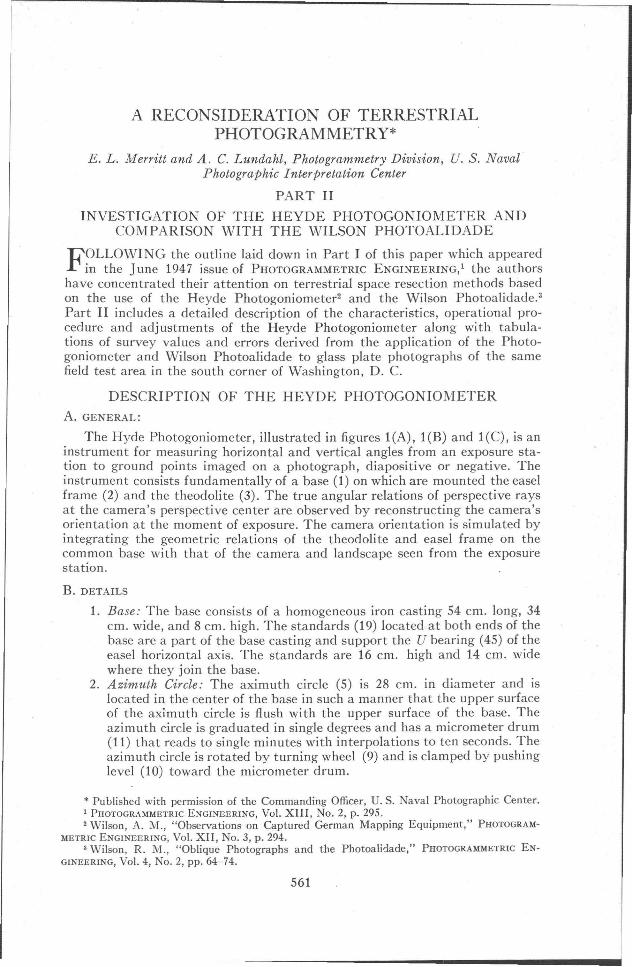
The Hyde Photogoniometer, illustrated in figures l(A), l(B) and l(C), is aninstrument for measuring horizontal and vertical angles from an exposure station to ground points imaged on a photograph, diapositive or negative. Theinstrument consists fundamentally of a base (1) on which are mounted the easelframe (2) and the theodolite (3). The true angular relations of perspective raysat the camera's perspective center are observed by reconstructing the camera'sorientation at the moment of exposure. The camera orientation is simulated byintegrating the geometric relations of the theodolite and easel frame on thecommon base with that of the camera and landscape seen from the exposurestation.
B. DETAILS
1. Base: The base consists of a homogeneous iron casting 54 em. long, 34em. wide, and 8 em. high. The standards (19) located at both ends of thebase are a part of the base casting and support the U bearing (45) of theeasel horizontal axis. The standards are 16 em. high and 14 em. widewhere they join the base.
2. Azimuth Circle: The aximuth circle (5) is 28 em. in diameter and islocated in the center of the base in such a manner that the upper surfaceof the aximuth circle is flush with the upper surface of the base. Theazimuth circle is graduated in single degrees and has a micrometer drum(11) that reads to single minutes with interpolations to ten seconds. Theazimuth circle is rotated by turning wheel (9) and is clamped by pushinglevel (10) toward the micrometer drum.
* Published with permission of the Commanding Officer, U. S. Naval Photographic Center.1 PHOTOGRAMMETRIC ENGINEERING, Vol. XIII, No.2, p. 295.2 Wilson, A. M., "Observations on Captured German Mapping Equipment," PHOTOGRAM
METRIC ENGINEERING, Vol. XII, No.3, p. 294.3 Wilson, R. M., "Oblique Photographs and the Photoalidade," PHOTOGRAMMETRIC EN
GINEERING, Vol. 4, No.2, pp. 64-74.
561
562 PHOTOGRAMMETRIC ENGINEERING
27
'H"",,,-34-
FIG. 1(A). Photogoniometer-side oblique view.
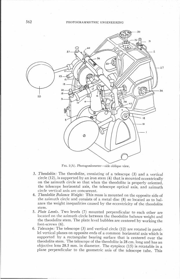
3. Theodolite: The theodolite, consisting of a telescope (3) and a verticalcircle (12), is supported by an iron stem (4) that is mounted eccentricallyon the azimuth circle so that when the theodolite is properly oriented.the telescope horizontal axis, the telescope optical axis, and azimuthcircle vertical axis are concurrent.
4. Theodolite Balance Weight: This mass is mounted on the opposite side ofthe azimuth circle and consists of a metal disc (8) so located as to balance the weight inequalities caused by the eccentricity of the theodolitestem.
5. Plate Levels. Two levels (7) mounted perpendicular to each other arelocated on the azimuth circle between the theodolite balance weight andthe theodolite stem. The plate level bubbles are centered by working thefoot-screws (6).
6. Telescope: The telescope (3) and vertical circle (12) are rotated in parallel vertical planes on opposite ends of a common horizontal axis which issupported by a rectangular bearing surface that is centered over thetheodolite stem. The telescope of the theodolite is 28 em. long and has anobjective lens 28.5 mm. in diameter. The eyepiece (15) is rotatable in aplane perpendicular to the geometric axis of the telescope tube. This
RECONSIDERATION OF TERRESTRIAL PHOTOGRAMMETRY
J'
9
Fig. l(B). Photogoniometer-front view.
563
feature allows the observer to view the negative plate by merely lookingdownward into the telescope eyepiece. The negative plate is broughtinto sharp focus by working focus screw (16). The telescope level (17) islocated on the top of the telescope, parallel to the telescope tube.
7. Vertical Circle of Theodolite: The vertical circle (12), supported on theopposite end of the horizontal telescope axis, is 13 em. in diameter and2.25 em. thick. It is graduated to single degrees and has two micrometerdrums (13) 1800 apart that read to single minutes and may be interpolated to ten seconds. The vertical motion is clamped by rotating screw(14) which is mounted on the upper front side of the theodolite stem.The micrometer drums located on opposite sides of the vertical circleprovide equal facility in making both direct and reverse observations.
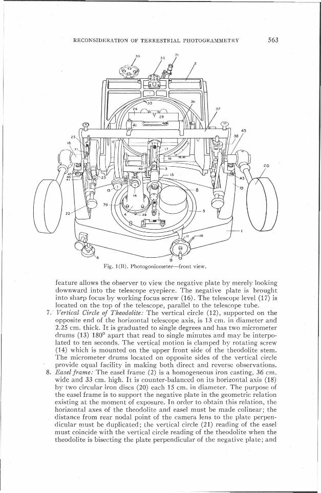
8. Easel frame: The easel frame (2) is a homogeneous iron casting, 36 em.wide and 33 em. high. It is counter-balanced on its horizontal axis (18)by two circular iron discs (20) each 15 em. in diameter. The purpose ofthe easel frame is to support the negative plate in the geometric relationexisting at the moment of exposure. In order to obtain this relation, thehorizontal axes of the theodolite and easel must be made colinear; thedistance from rear nodal point of the camera lens to the plate perpendicular must be duplicated; the vertical circle (21) reading of the easelmust coincide with the vertical circle reading of the theodolite when thetheodolite is bisecting the plate perpendicular of the negative plate; and

564 PHOTOGRAMMETRIC ENGINEERING
the horizon line of the negative plate must be parallel to a line defined bythe trace of the telescope cross-hair intersection when the telescope isrotated in azimuth. The easel is perhaps best described by a brief statement on the part it plays chronologically in the operational procedure.First, the common base is leveled up, after which the theodolite is oriented with respect to the base and the easel is oriented with respect tothe theodolite. Once the orientation sequence is accomplished, the vertical circle level (25), located on the left side just above the easel's horizontal axis, is made to be centered when the·easel's vertical circle (21)reads 0°.
9. Easel Vertical Circle: The easel vertical circle is graduated to single degrees and has a vernier that may be read to thirty seconds. The vernieris observed through one of the twin oculars (23) attached symmetricallyopposite to each other on the front and rear edge of the easel verticalcircle case. In practice, the complement of tilt of the camera is set on theeasel vertical arc by rotation of screw (22) located directly below and infront of the easel vertical arc. This angular relation is then retained by'adjusting set screw (24), located on the back upper surface of the base,until the set screw's upper point contacts and supports the easel frame.
10. Rear Ground Glass Window: The easel has a circular opening 23.5 em. indiameter in the rear through which the negative plate may be passed tothe plate holder (26). Once the negative plate is installed, a circularground glass window (27) is fitted into the circular opening. The light
2.
2.6 --l1+----ttl:H1
FIG. 1(C). Photogoniometer-rear oblique view.

RECONSIDERATION OF TERRESTRIAL PHOTOGRAMMETRY 565
source of the negative plate is admitted through this window.11. Plate Holder: The plate holder will accommodate a 180 mm. X 130 mm.
negative plate. The plate is held secure by spring pressure of the photoplate clamp (29) located on 'the upper edge of the plate holder. The plateholder has two half-circle depressions on the upper edge and one halfcircle depression on the lower edge to accommodate the fingers wheninstalling the negative plate. The photo spring clamp forces the negativeplate to bear against three small supports projecting from the edge of theplate holder in the plane of the installed negative plate. The surfaces ofthese supports are coplanar on the side toward the negative plate.
12. I Motion: After the negative plate is installed, the focal distance of thetaking camera is set on the instrument by working the I scale settingscrew (30) located on the upper left surface of the easel. The setting isread in the f scale ocular (31) located on the upper right rear surface ofthe easel.
13. X Motion: The line connecting upper and lower fiducial marks is madeto pass through the cross-hair intersection of the telescope by working Xscrew (33) located on the middle back left side of the easel.
14. Y Motion: The line connecting left and right fiducial marks is made topass through the cross-hair intersection of the telescope by working Yscrew (32) located on the middle back upper surface of the easel.
15. Swing Motion: The horizon line is made parallel with the trace of thetelescope cross-hair intersection when rotated in azimuth by working S(swing) Screw (34) located on the middle back right side of the easel.'The gear of the S screw engages the rack of the swing circle (35) locatedon the inside back face of the easel frame. The swing circle is graduatedto single degrees and has a vernier that may be read to single minutes.
16. Striding Level: The striding level (37) is used to make the horizontal axisof the easel parallel in any horizontal plane with the theodolite horizontal axis.
17. Auxiliary Easel Level: The auxiliary easel level (38) is used to check thevertical orientation of the easel after it has been established and clamped.
OPERATIONAL PROCEDURE FOR THE HEYDEPHOTOGONIOMETER
As described in paragraphs 10 and 11, the negative plate is installed in theplate holder and the ground glass window fit in the rear access frame. The baseis leveled by manipulating the three foot screws. The appropriate focal distanceof the taking camera is set on the focal scale drum by turning the I scale screw.At this point, the complement of the angle of tilt of the taking camera is set onthe vertical circles of the easel and the theodolite. The azimuth circle is thenmade to read 0°. To make the principal point of the negative plate coincide withthe crosshair intersection of the telescope, the X and Y screws are alternatelyand appropriately turned while the original settings of .the azimuth circle andrespective vertical circles are maintained. A line connecting the left and rightfiducial marks is then made to coincide with a line defined by the trace of thehorizontal rotation of the telescope crosshair intersection. This is accomplishedby making appropriate rotation of the plate holder. The vertical crosshair shouldcoincide with the line connecting the upper and lower fiducial marks when thetelescope is rotated in a vertical plane, if the easel, theodolite and base arecorrectly oriented with respect to each other. The horizontal and vertical anglesof image points may be read directly if and when the negative plate is orientedin I, x, y, and s respectively.

566 PHOTOGRAMMETRIC ENGINEERING
Selected images are bisected with the telescope crosshairs, and the verticaland horizontal angles are read and recorded. The vertical angles represent thetrue vertical angles above or below the horizontal plane passing through thecamera lens. Horizontal angles represent the true horizontal angles left and rightof the principal plane. Inasmuch as the principal line was made to read zeroazimuth, there is no need to record the sign of the angles as the minus valueswill be near 360°, or in the fourth quadrant, and the plus values will be less than90° and in the first quadrant. The horizontal and vertical angles of each imageare measured at least two times direct and an equal number of times reverse tocancel out collimation error. The plus horizontal angles are unchanged whereasthe minus horizontal angles are deduced by substracting the mean of the leftreadings on a single frame from 360°.
The operational procedure for the Heyde Photogoniometer is simple andfast, once the instrument is in correct adjustment. In a recent test, no more thantwenty minutes total time were required to observe two direct and two reversereadings on a negative plate having eight ground objects imaged. Somewhat lessthan twenty minutes were required to orient each negative plate with respect toj, x, y, and s settings. However, the adjustments of the theodolite with respectto the base and the easel with respect to the theodolite are more involved andtherefore require a considerably longer period of time.
ADJUSTMENTS OF THE HEYDE PHOTOGONIOMETER
A. GENERAL:
Certain geometric conditions must be satisfied before the observed horizontaland vertical angles duplicate the angles made by the perspective rays at theperspective center. These conditions are listed as follows in the order in whichthey are normally corrected.
1. The top of the base must coincide with a horizontal plane passing throughthe foot of the theodolite stem.
2. Horizontal and vertical axes of the telescope and the vertical axis of theazimuth circle must be concurrent.
3. The horizontal axis of the telescope must be colinear with the horizontalaxis of the easel, and these colinear axes must be parallel with the horizontal plane passing through the foot of the theodolite stem. Likewise, thevertical arc of both easel and telescope must have the same reading whenthe telescope is bisecting the principal point of the negative plate.
4. The optical axis of the telescope must be perpendicular to the negativeplate when the telescope crosshairs are bisecting the fiducial axes intersection and the perpendicular distance from the fiducial axes intersectionto the colinear easel and telescope axes must be equal to the focal lengthof the taking camera.
Inasmuch as several separate mechanical adjustments are required in mostinstances to satisfy a specific geometric condition, a second list is given whichconsists of the actual mechanical adjustments in the chronological order in whichthey are made.
la. Plate Levels2a. Eccentricity of the telescope3a. Horizontal Crosshair (Index Error)4a. Telescope LevelSa. Leveling Easel Horizontal Axis (Striding Level)6a. Making X axis of Negative Plate perpendicular to the Optical Axis of the
Telescope

RECONSibERATioN OF tERRESTRIAL PHOTOGRAMMETRY 567
7a. Making Yaxis of Negative Plate perpendicular to the Optical Axis of theTelescope
8a. Making the Level Easel Horizontal Axis to be in the same horizontalplane as the Telescope Horizontal Axis.
9a. Making the Horizontal Easel and Telescope Axes to be in the same vertical plane when they are in the same horizontal plane (Focal distanceadjustment).
B. PROCEDURE:
1. Plate Level Adjustment. The plate level bubbles are centered by turningthe three foot screws-two on the left and one on the right. After thebubbles have been centered, the azimuth circle is rotated through 180°.If the bubbles are no longer centered, the ground glass arcs of the bubblesare not parallel to the top of the base and the plate levels themselves mustbe adjusted. Half the bubble error is corrected by altering the inclinationof the plate levels with an adjusting pin and the remaining half by turningthe foot screws. The azimuth circle is then rotated back to its originalposition and the bubbles are again checked for residual error. If the bubbles are still not exactly centered, the adjusting procedure is repeateduntil the bubbles are centered in both positions. The whole procedure isidentical with the plate level adjustment on any field transit.
2. Eccentricity of the Intersection of Telescope Horizontal and Optical Axeswith Respect to Axis of Rotation of the Azimuth Circle. Fig. 2. The telescopeis leveled and the projection of the crosshair intersection is marked on adistant target. Both azimuth circle and vertical circle are rotated through180°, and the projection of the crosshair intersection again marked on thedistant target. The horizontal separation of the two marks on the distant
t-ioTiz.onto.\ Plane tht'ou,h To.1'",etonol Tc.lc.acor& L-
ltrrot'
Optico.l O,xi$Oin.ct
Rev. rae.
-+_[c_c_..n_tT_ic....:ity_o_n_._I<l4_c....:oP~..----l.j<:.':A~x~i.~of~Ro~to~t.:::io::.:n~o~f~A~ci~m~th~C"-'ir~c\:::...------------1- ~ double
Pla.fl Vit.w
FIG. 2. Eccentricity of telescope.
target is equal to double the horizontal eccentricity of the telescope. Withreference to figure 1(B), there are four adjusting pins (39) perpendicularto and in the base of the theodolite stem. A mark is noted midway between the two marks on the distant target. By manipulating adjustingpins (39), the vertical crosshair of the telescope is made to bisect the midmark noted. This operation is repeated, if necessary, until no eccentricity

568 PHOTOGRAMMETRIC ENGINEERING
exists. The adjusting pins located in the telescope tube carriage, and bearing against the tube, may be used to remove small residual eccentricities.
3. Adjusting the Horizontal Crosshairs. Figs. 3(A) and 3(B). A telescope sightis made on a distant target (a blackboard was used in this test) with thetheodolite vertical'arc reading 0° 0' 0" and the projection of the crosshairintersection on the target is noted (a). The azimuth and vertical circlesof the telescope are rotated through 180° and the projection of the crosshair intersection on the target is again noted (b). The theodolite verticalarc is then clamped and the appropriate adjusting pins are manipulateduntil the horizontal crosshair bisects c, a mark placed half way between aand b along a vertical line on the target. When the direct and reversebisections of care 180° apart, the adjustment is complete.
'I'-'IL- +-_.P:.-'_'"_~_.'_.--.L...l.I1i
fiS 3(A)
IfHi I III~'-----+-__-...L..I-.lI1i
fIg 3iB)
Direct O· 00' 00'
180· 00' 00'
(V£. rlu: a I plane 'through 'ta.rS ..t
and Tq,tltscorq,
0·00'00'180·00'00"
FIG. 3(A) (B). (Index error.)
4. Adjustment of the Telescope Level. Fig. 4. To this point, adjustments havebeen so made that a line, defined by the crosshair intersection and theprojected point of crosshair intersection on the target, passes through aline defined by the horizontal axis of the telescope. However, the formerline is not necessarily parallel to a plane tangent to the arc of the centeredbubble of the telescope level. The telescope bubble is centered when thevertical arc of the theodolite reads 0°. To make the necessary adjustment,a target on a Philadelphia Level Rod is bisected at a known distance andthe vertical arc reading of the horizontal crosshair on the target is recorded. The horizontal and vertical circles are transited through 180°,and a second reading on the target is recorded. The level error is equal toal2 and tan al2 =!1hI2D where!1h is the difference between the two leveltarget readings and D is the distance from the target to the intersection ofhorizontal and vertical axes of the telescope. The vertical circle may beadjusted for a12, but the simplest solution is to treat it as an index errorof a12, which is applied algebraically to all vertical angles.
5. Leveling the Easel Horizontal Axis. Fig. 5. Up to now, the easel has beendetached from the standards because in the foregoing adjustments it was

RECONSIDERATION OF TERRESTRIAL l'HOTOGRAMMETRY 569
Levct! Dirtct
Horiz'--on-1-"'I----+--=-~--lex.Ax is of Tr'I_U_c--,-oP_"__-+---=:::....~----,
lc.vc\ Rc.\It.y~~
Vc.rtlC~ol p'one.
FIG. 4. Telescope level adjustment.
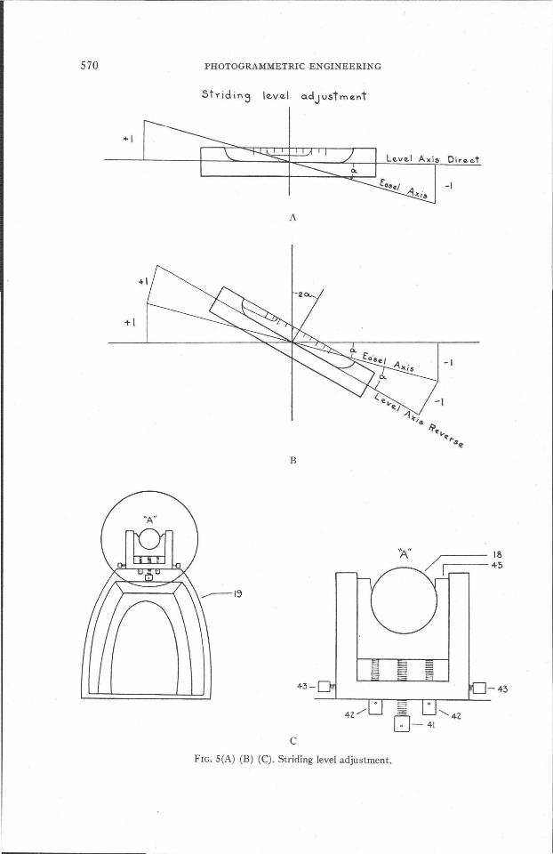
not required. The easel horizontal axis is carefully placed in the" U" bearing (45) Fig. lA, located on the top of standards (19). The striding level(37) is carefully placed on the exposed easel axis. The bubble is centeredby manipulating the appropriate adjusting pins (40) on the striding leveltube. The position of the striding level is then reversed on the easel axis.The mean reading of the two ends of the bubble in the reverse position,subtracted from the mean of the two ends of the bubble when centered,times the value of one bubble division in arc is equal to twice the deviationof the easel axis from the horizontal. Obviously, then, one-half the errormust be taken up by adjusting the easel axis and the other half by adjusting the striding level bubble. The error doubling is illustrated in figuresSeA) and S(B). Beneath the top of both standards are three vertical adjusting pins shown in figure S(C). Half the bubble error is removed byworking the adjusting pins (42) and (43) in the opposite direction, in avertical plane; one set is located beneath the top of the left standard,while a duplicate set is located beneath the top of the right standard, eachworking so as to bear vertically upward against opposi te ends of theeasel horizontal axis. The remaining half of the bubble error is removed byadjusting pins (40) on the striding level proper. The striding level is thenplaced in the initial direct position, and the residual error, if any, is noted.The procedure is repeated until the bubble is centered in both positions.At this point the horizontal axes of the telescope and the easel are both ina horizontal plane but not necessarily in the same plane.
6. Making the X axis of the Easel Perpendicular to the Optical Axis of theTelescope. Fig. 6. A calibration plate having two lines intersecting at a 90°angle is installed ineasel plate holder. The terminals of the horizontal lineare designated x and x', while the terminals of the vertical line are designated y and y' as shown in figure 6. The intersection 0 is equidistant fromy and y', x and x'. The horizontal and vertical circles are each made toread 0°. By manipulating the x, y, and z screws, the horizontal crosshairof the telescope coincides with xx', the vertical crosshair coincides with
570 PHOTOGRAMMETRIC ENGINEERING
Lez.VlZ.1 A)(i~ Direet
+-1
-I
A
+1
B
IBr---- 45
'A"
4.3-0
cFIG. SeA) (B) (C). Striding level adjustment.

RECONSIDERATION OF TERRESTRIAL PHOTOGRAMMETRY
nEEoo-:
IIf----ao.oo mm -------+-f----ao.oo m~-------11
Eoq-t
FIG. 6. Calibration plate.
571
x
Colilor ..tion Plote.
- EO$ .. 1 Axis
L ----.Ep~O"_AX.i5
FIG. 7. Horizontal plane through telescope optical axis and XOX'.
572 PHOTOGRAMMETRIC ENGINEERING
yy', and the crosshair intersection is at o. Since ox = ox', a will equal {3when a vertical plane passing through the easel.horizontal axis is parallelto a vertical plane passing through the telescope horizontal axis. AnglesxLo and oLx' are observed and found to be a' and W, respectively, because the optical axis of the telescope fails to be perpendicular to xox' byan angular increment equal 11°. The failure of the optical axis to be perpendicular to xox' is illustrated in figure 7. The angle 11 is computed asillustrated in figure 8.
xo' = 2 sin a' . R and x'0' = 2 sin {3' . R
xx'R=-----
2 sin \0'.' + (3')
(00')2 = (XO')2 + (XO)2 - 2(xo')(xo) ·cos {3
xo·sin {3'sinp = ---
00'where xoL = {3' + p
= 90° - ({3' + p).
The azimuth circle is adjusted to the angular correction of 11°. The observation is repeated until a={3, when angles are measured between x and 0
and 0 and x' respectively, at L.
0'
LFIG. 8. Same plane as Figure 7.
x ~::"--T-T-""'~---r-r~'""-L----'"---C"J;bn"tion pl",'\(.
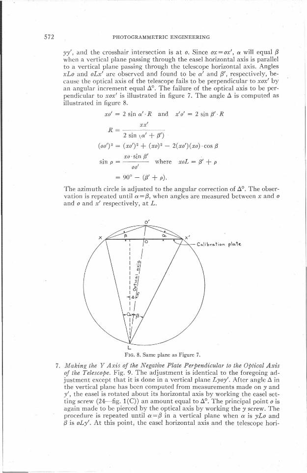
7. Making the Y Axis of the Negative Plate Perpendicular to the Optical Axisof the Telescope. Fig. 9. The adjustment is identical to the foregoing adjustment except that it is done in a vertical plane Lyoy'. After angle 11 inthe vertical plane has been computed from measurements made on y andy', the easel is rotated about its horizontal axis by working the easel setting screw (24-fig. l(C)) an amount equal to 11°. The principal point 0 isagain made to be pierced by the optical axis by working the y screw. Theprocedure is repeated until a={3 in a vertical plane when a is yLo and{3 is oLy'. At this point, the easel horizontal axis and the telescope hori-
RECONSIDERATION OF TERRESTRIAL PHOTOGRAMMETRY
Te.lesc.opcz..ho,.,zonto.lo.)cIS
FIG. 9. Vertical plane through telescope optical axis.
573
~I
v
T~I ..s cop'"hO'f.o.Kis
v·
/~- +~'r"ou ..
F;gtFIG. 10. Principal plane passing through optical axis.

574 PHOTOGRAMMETRIC ENGINEERING
zontal axis have been made to be in parallel horizontal planes and parallelvertical planes, but these are not necessarily identical horizontal andvertical planes.
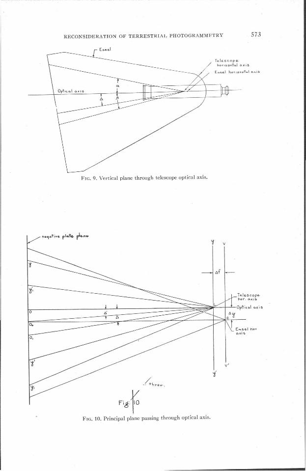
8. Making the Easel Horizontal Axis and the Telescope Horizontal Axis Lie inthe Same Horizontal Plane. In figure 10 oL is parallel to 00e and yy' is parallel to vv'. The telescope horizontal axis and easel horizontal axis are displaced in the horizontal plane by an amount t:.j and in the vertical planeby an amount t:.y. To make t:.y=o, the following adjustments are made:The leveled telescope is made to bisect 0 on the calibration plate. Thecalibration plate is then rotated through 1800 by turning screw S (34).If t:.y = 0, the principal point will not move, as it will represent the axis ofrotation. If t:.y~o, the principal point will describe a half circle whoseradius will be t:.y.
2Ay = j. tan A' andyo
j=--tan av
orXo
tan an
2AyAy=-
2
Aytan A' = -.
j
Angle t:.' is set on the telescope vertical arc. The easel is then elevated orlowered, as the case may be, by working the easel setting screw and theadjusting pins beneath the top of both easel standards. Each of the threescrews is turned an equal amount in the same direction so that the easelwill be corrected in a plane parallel to that previously held, an amount
Dir~e" r:
V&rtieo.l plo."& throu,\h~Q!.e.l h()"i~ontc.,\ 0.)(·15
I-----Verticol plane throv,\h'telcesclJpe horix.ol"\io.\ Q,xi.,
FIG. 11. Vertical plane through Ly'y.

RECONSIDERATION OF TERRESTRIAL PHOTOGRAMMETRY 575
vertically equal. to .1y. The easel is moved vertically until the image 0 isagain bisected by the telescope vertical arc. This adjustment is mostdifficult and may necessitate repeating some of the previous adjustmentsas it is almost impossible to elevate the easel to each of three points anexactly equal amount.
9. Focal Length Setting Calibration. Fig. 11. The purpose of this last adj ustment is twofold: First, to determine the error, if any, of the focal lengthscale. Second, to make the easel horizontal axis and the telescope horizontal axis lie in the same vertical plane. The telescope is leveled and ismade to bisect 0 with line yy' perpendicular to Lo in the principal plane.The vertical angle, yLy', is measured with the easel in the direct positionand re-observed with the easel in the reverse position. If the easel horizontal axis and the telescope horizontal axis were in the same vertical plane,angle a in the direct position would equal a' in the reverse position, sinceboth axes are in the same horizontal plane and yy' = y'y. However,this condition is rarely true. The horizontal difference of the two verticalplanes is equal to .1]=]: -j{ when
yy' afo' = - cot-,
2 2
yy' a'it' = - cot-
2 2
yy' a yy' a' yy'(a a' )J).f = 2 cot 2 - 2 cot 2 = 2 cot 2 - cot 2
= yo ( cot ; - cot ~' ) .
The easel is shifted in a horizontal plane so that the horizontal axis of thetelescope and horizontal axis of the easel are in the same vertical plane.This is accomplished by turning adjusting pins, (41 and 42) shown infigure 1. The angles a and a' are observed alternately with the shiftingof the easel in the horizontal plane until a=a' and .1]=0. When .1]=0,yy' /2· cot a/2 should equal the reading on the focal length drum. If thecomputed] in millimeters does not equal the value in millimeters read inthe f ocular, the] scale drum must be adjusted for the difference, or thedifference applied as a correction to the focal length indicated on the]scale drum. The latter method is preferred. As has been mentioned previously, the adjustments of the photogoniometer are so interrelated thatmany of the adjustments must be repeated because they are in turn altered by adjustments that follow. These tedious time-consuming adjustments, the excessive weight of the instrument, and the near necessity of astable (concrete) base are the three paramount objections to the HeydePhotogoniometer.
COMPARISON OF ACCURACY OF THE HEYDE PHOTOGONIOMETER AND THE WILSON PHOTOALIDADE
A. GENERAL:
The Heyde Photogoniometer was tested for its accuracy in establishing thehorizontal and vertical coordinates of ground objects by triangulation methods.As detailed in Part 1,4 two stations, A and B, 19,303.89 feet apart at the southcorner of Washington, D. C. were occupied by a Navy field party using a Fair-
4 PHOTOGRAMMETRIC ENGINEERING, Vol. XIII, No.2, p. 308.
576 PHOTOGRAMMETRIC ENGINEERING
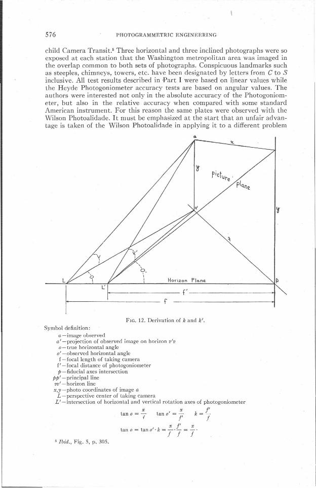
child Camera Transit.- Three horizontal and three inclined photographs were soexposed at each station that the Washington metropolitan area was imaged inthe overlap common to both sets of photographs. Conspicuous landmarks suchas steeples, chimneys, towers, etc. have been designated by letters from C to Sinclusive. All test results described in ·Part I were based on linear values whilethe Heyde Photogoniometer accuracy tests are based on angular values. Theauthors were interested not only in the absolute accuracy of the Photogoniometer, but also in the relative accuracy when compared with some standardAmerican instrument. For this reason the same plates were observed with theWilson Photoalidade. It must be emphasized at the start that an unfair advantage is taken of the Wilson Photoaliciade in applying it to a different problem
f---------f'-----------+I
L
FIG. 12. Derivation of k and k'.
Symbol definition:a - image observed
a' -projection of observed image on horizon v'vo-true horizontal angle
0' -observed horizontal anglef - focal length of taking camera
f' - focal distance of photogoniometerp-fiducial axes intersection
pp' -principal linevv' - horizon linex,y-photo coordinates of image a
L -perspective center of taking cameraL'-intersection of horizontal and vertical rotation axes of photogoniometer
tan 0 = -=- tan 0' = -=- k = tf I' I
x f' xtan 0 = tano'·k = -'- =_.
I I I5 Ibid., Fig. 5, p. 305.

RECONSIDERATION-OF TERRESTRIAL PHOTOGRAMMETRY S77
than that for which it was designed. Nevertheless, the tests were executed inorder to secure some data on the relative precision of these instruments. Onemore correction had to be made before starting to tabulate survey values inasmuch as the maximum focal length range of the Photogoniometer was not equalto that of the taking camera. Therefore, a false f was used. The observed horizontal and vertical angles were corrected by multiplying the tangent of the observed values by a constant whose derivation is illustrated in figure 12.The tangent of any observed horizontal angle multiplied by constant k is equalto the tangent of the true horizontal angle at the perspective center of the takingcamera.
ytan v =
La'
tan v" = tan v' . k
y y l'-:==-.-
f l' f
cos 0 =!La'
tan v = tan v' . cos O· k
y y l' for -=_._.-.La' l' f La'
Since both horizontal and vertical angles at the perspective center of the cameramay be easily derived by multiplying the tangents of observed horizontal andvertical angles, respectively, by a common constant, no great inconvenienceresults from not being able to observe at the focal length of the taking camera.
In Tables 1 and 2 are listed the survey values derived from angles observedwith the Wilson Photoalidade and Heyde Photogoniometer respectively. Thesevalues may be compared station for station with the true survey values listed
TABL I-Tabulation of Survey Values Derived from Angles Observed withthe Wilson Photoalidade-in Feet
Station I Distance fromA I B
CoordinatesX I Y
ElevationJZ
C 605.96D 18,043.10 12,096.99 12,010.78 5,706.09 371.02E 22,474.56 27,081.41 23,161.40 16,261. 29 349.57F 22,909.67 27,341.64 23,578.14 16,116.65 353.04G 22,596.78 27,039.32 23,250.57 16,059.61 348.98H 30,870.41 30,839.08 30,306.20 10,297.97 417.53I 8,725.59 18,393.16 9,243.12 17,138.72 138.90J 29,047.48 28,677.80 28,195.97 9,795.31 385.94K 16,741.49 20,050.05 16,428.55 13,500.97 267.14L 23,661. 76 20,360.08 20,490.33 6,583.37 256.52M 14,469.12 15,609.79 12,513.50 11,236.74 326.18N 20,928.43 16,135.36 16,324.55 5,746.67 275.820 19,008.02 11 ,457 .38 11,845.64 4,389.85 287.73P 14,143.60 10,947.40 8,903.71 8,270.86 209.28Q 18,895.03 10,426.69 10,916.88 3,916.55 195.62R 13,043.30 10,500.13 7,680.20 8,797.20 147.00S 14,762.44 5,604.76 3,858.74 5,517.00 143.58

578 PHOTOGRAMMETRIC ENGINEERING
in Table 7, Part I of this paper. 6 Tables 3 and 4 have been used to tabulate theerrors of survey values derived from Wilson Photoalidade angles and Photogoniometer angles. It is readily noted that the Heyde Photogoniometer is notonly much more accurate than the Wilson Photoalidade, but it has an absoluteposition accuracy exceeding the specifications of fourth order control when theintersecting perspective rays are no longer than five miles. This is obviously nottrue for the Wilson Photoalidade. The time required to make a series of measurements on a single exposure is approximately the same for both instruments.
TABLE 2 -Tabulation of Survey Values Derived from Photogoniometer Angles-in Feet
Station I Distance fromA I B
CoordinatesX I Y
ElevationZ
C 11 ,651.11 15,401.38 10,295.70 ,12,975.88 588.75D 18,029.01 12,102.48 12,009.25 5,722.68 367.76E 22,466.68 27,074.66 23,153.37 16,260.99 347.36F 22,874.62 27,323.82 23,545.39 16,132.97 354.95G 22,600.92 27,047.11 23,255.84 16,065.68 346.86H --I 8,726.05 18,391. 37 9,242.94 17,136.81 125.02J 28,957.09 28,576.09 28,093.74 9,780.29 405.80K 16,761.42 20,062.06 16,448.15 13,496.15 257.58L 23,633.42 20,330.74 20,458.53 6,587.17 246.69M 14,481.29 15,615.07 12,525.10 11 ,231.88 309.81N 20,955.90 16,152.54 16,347.70 5,731.24 298.350 19,008.11 11,494.61 11 ,877 .46 4,411.89 280.78P 14,147.38 10,972.04 8,927.09 8,282.08 203.03Q 18,901.68 10,462.70 10,950.54 3,929.52 192.29R 13,025.73 10,524.67 7,688.16 8,822.43 142.50S 14,753.70 5,613.47 3,860.27 5,526.21 137.62
TABLE 3 -Tabulation of Error in Survey Values Derived fromWilson Photoalidade Angles-in Feet
Coordinate Error Position Error Ratio of Precision
Station
I I
DA+DBt:..X iY t:..Z V(t:..X)2+ (t:.. Y)2
W(t:..X)2+(t:..y)2
C 0 0 11.93 -- ---D 2.93 -15.96 - 2.65 16.23 1: 930E 17.92 1.69 3.21 18.00 1:1,380F 19.56 -15.94 9.96 25.23 1:1,000G 11.05 - 2.42 6.09 11.31 1:2,200H -78.43 3.30 - 7.58 78.50 1: 390I 9.27 1.61 2.44 9.41 1:1,440J 119.57 20.42 - 4.94 121. 30 1: 240K -22.41 2.48 5.54 22.55 1: 820L 39.88 - 0.95 7.51 39.89 1: 550M -10.10 6.15 13.00 11.83 1:1,270N -17.81 14.91 -24.42 23.23 1: 8000 -27.69 -22.02 4.71 35.38 1: 430P -21.64 -11.68 - 1.13 24.59 1: 510Q -23.81 -10.29 - 4.52 25.94 1: 570R - 7.33 -22.88 6.10 24.03 1: 490S 0.90 - 3.48 3.15 3.59 1:2,840
±6.96 ±27.50 1:1,031
6 PHOTOGRAMMETRIC ENGINEERING, Vol. XIII, No.2, p. 309.
RECONSIDERATION OF TERRESTRIAL PHOTOGRAMMETRY 579
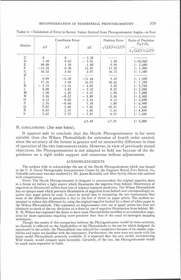
TABLE 4 -Tabulation of Error in Survey Values Derived from Photogoniometer Angles-in Feet
Coordinate Error I Position Error Ratio of Precision
Station
IIy(toX)2+ (to Y)2
DA+DBtoX toY toZ
2y(toX)2+(toY)2
C 0 0 - 5.28 --D 1.40 0.63 - 5.91 1.50 1:10,040E 99.89 1.39 1.00 9.99 1: 2,480F -13.19 0.38 11.87 13.20 1: 1,900G 16.32 3.65 3.97 16.72 1: 1,480H -- -- -- --I 9.09 -0.30 -11.44 9.10 1: 1,490J 17.34 5.40 14.92 18.16 1: 1,580K - 2.19 -2.34 - 4.02 3.20 1: 5,740L 8.08 2.85 - 2.32 8.57 1: 2,560M 1.50 1.29 - 3.37 1.98 1: 7,600N 5.34 -0.52 - 1.89 5.36 1: 3,4600 4.13 0.02 - 2.24 4.13 1: 3,690P 1. 74 -0.46 7.38 1.80 1: 6,980Q 9.85 2.68 - 7.85 10.21 1: 1,440R 0.63 2.35 1.60 2.43 1: .4,850S 2.43 5.73 - 2.81 6.22 1: 1,640
±5.49 ±7.51 1: 3,800
B. CONCLUSIONS: (See note below).
It appears safe to conclude that the Heyde Photogoniometer is far moresuitable than the Wilson Photoalidade for extension of fourth order control,since the accuracy of the former is greater and no noteworthy difference in timeof operation of the two instruments exists. However, in view of previously statedobjections, the Photogoniometer is not adapted to field use because of the dependence on a rigid stable support and numerous tedious adjustments.
ACKNOWLEDGMENTS
The authors wish to acknowledge the use of the Heyde Photogoniometer which was loanedto the U. S. Naval Photographic Interpretation Center by the Engineer Board, Fort Belvoir, Va.Valuable assistance was also rendered by Mr. James Kowalski and Miss Sylvia Adams who assistedwith computations.
NOTE: The Heyde Photogoniometer is designed to accommodate the original negative platein a frame set before a light source which illuminates the negative from behind. Observation ofnegatives so illuminated suffers least loss of original exposure resolution. The Wilson Photoalidadehas an opaque easel which prevents illumination of negatives from behind and correspondingly requires that paper prints be used. It must be noted then in comparing the two instruments thatsome of the difference in precision is due to the loss of detail on paper prints. The authors attempted to reduce this difference by using the original negative backed by a sheet of white paper inthe Wilson Photoalidade. This represents an improvement over use of paper prints but does noteliminate as much of the ray deviation as is done by use of negative illumination from behind. Mr.R. M. Wilson has expressed the desire to have some Photoalidades modified to accommodate negatives for those operations requiring more precision than that of the usual tri-metrogon mappingtechniques.
Though the results of this comparison indicate the Photogoniometer would be more accurate,no discredit is reflected on the Applicability of the Photoalidade to the use for which designed. Asmentioned in the article, the Photoalidade was selected for comparison because of its similar capabilities and many are familiar with the instrument. Furthermore, the tests were not made with thelatest model Photoalidade presently available. It is expected that the new model, incorporatingWild transit, would compare more favorably. Certainly, of the two, the Photogoniometer wouldbe much more expensive to build.