a reverse engineering methodology for extracting
TRANSCRIPT

Louisiana State UniversityLSU Digital Commons
LSU Historical Dissertations and Theses Graduate School
1996
A Reverse Engineering Methodology for ExtractingParallelism From Design Abstractions.Ravi Chandra ErraguntlaLouisiana State University and Agricultural & Mechanical College
Follow this and additional works at: https://digitalcommons.lsu.edu/gradschool_disstheses
This Dissertation is brought to you for free and open access by the Graduate School at LSU Digital Commons. It has been accepted for inclusion inLSU Historical Dissertations and Theses by an authorized administrator of LSU Digital Commons. For more information, please [email protected].
Recommended CitationErraguntla, Ravi Chandra, "A Reverse Engineering Methodology for Extracting Parallelism From Design Abstractions." (1996). LSUHistorical Dissertations and Theses. 6336.https://digitalcommons.lsu.edu/gradschool_disstheses/6336

INFORMATION TO USERS
This manuscript has been reproduced from the microfilm master. UMI
films the text directly from the original or copy submitted. Thus, some
thesis and dissertation copies are in typewriter face, while others may be
from any type of computer printer.
The quality of this reproduction is dependent upon the quality of the copy submitted. Broken or indistinct print, colored or poor quality
illustrations and photographs, print bleedthrough, substandard margins,
and improper alignment can adversely afreet reproduction.
In the unlikely event that the author did not send UMI a complete
manuscript and there are missing pages, these will be noted. Also, if
unauthorized copyright material had to be removed, a note will indicate
the deletion.
Oversize materials (e.g., maps, drawings, charts) are reproduced by
sectioning the original, beginning at the upper left-hand comer and
continuing from left to right in equal sections with small overlaps. Each
original is also photographed in one exposure and is included in reduced
form at the back of the book.
Photographs included in the original manuscript have been reproduced
xerographically in this copy. Higher quality 6” x 9” black and white
photographic prints are available for any photographs or illustrations
appearing in this copy for an additional charge. Contact UMI directly to
order.
UMIA Bell & Howell Information Company
300 North Zeeb Road, Ann Arbor MI 48106*1346 USA 313/761-4700 800/521-0600
Reproduced with permission of the copyright owner. Further reproduction prohibited without permission.

Reproduced with permission of the copyright owner. Further reproduction prohibited without permission.

A REVERSE ENGINEERING METHODOLOGY FOR EXTRACTING PARALLELISM
FROM DESIGN ABSTRACTIONS
A Dissertation
Submitted to the Graduate Faculty of the Louisiana State University and
Agricultural and Mechanical College in partial fulfillment for the degree of
Doctor of Philosophy
in
The Department of Computer Science
byRavi Chandra Erraguntla
B.E., Andhra University, 1985 M.E., Bharatiar University, 1989
M.S., Louisiana State University, 1993 December 1996
Reproduced with permission of the copyright owner. Further reproduction prohibited without permission.

UMI Number: 9720350
UMI Microform 9720350 Copyright 1997, by UMI Company. All rights reserved.
This microform edition is protected against unauthorized copying under Title 17, United States Code.
UMI300 North Zeeb Road Ann Arbor, MI 48103
Reproduced with permission of the copyright owner. Further reproduction prohibited without permission.

Dedicated to my parents Prof. Erraguntla Venkata Rao, D.Sc., Ph.D.
Erraguntla Kameswari, Ph.D.
ii
Reproduced with permission of the copyright owner. Further reproduction prohibited without permission.

Acknowledgments
I express my sincere gratitude to Dr. Doris L. Carver, my advisor and friend
who introduced me to the field of Software Engineering. Her knowledge and versatil
ity in the different areas of Software Engineering helped me gain invaluable insight
into software systems. She has been a constant source of inspiration and none of this
work could have been possible without her support and encouragement. She always
listened to what I had to say and provided advice on many issues. I am fortunate for
having been associated with her on research projects at Thermalscan Inc. and Medical
Thermal Diagnostics. I thank her for appointing me as the Laboratory Manager of the
Software Engineering Laboratory. I thank her for providing the facilities of the Soft
ware Engineering Laboratory.
I thank Dr. Mark L. Williams for introducing me to the field of Nuclear Engi
neering and for graciously agreeing to serve on my doctoral advisory committee. I
extend my appreciation to Dr. Donald H. Kraft, Dr. J. Bush Jones, and Dr. Suresh Rai,
members of my doctoral advisory committee, for reviewing my dissertation and for
offering their invaluable suggestions.
I owe thanks to the Graduate Assistantship committee of the Department of
Computer Science for providing financial assistance from August 1992. I thank Dr.
Sitarama S. Iyengar for providing the computing facilities Mr. Elias Khalaf for the ex
cellent system management.
iii
Reproduced with permission of the copyright owner. Further reproduction prohibited without permission.

Special thank goes to Mr. Jim and Ms. Sally Davidson of Thermalscan Inc. for
their love and affection. Members of the Software Engineering Group have created an
atmosphere which made the work described here possible. In particular, I would
cherish the friendship of Jigang Liu, Srinivas Lingineni, and Chenga Reddy.
Nothing would have been possible without the patient cooperation, constant
encouragement, and unconditional sacrifice of my wonderful wife Neeraja. She
helped me stay focused all the time. I am indebted to my parents Prof. E. Venkata Rao
and Dr. Kameswari for teaching me everything in life. I thank my in-laws Mr. K.S.N.
Murthy and Dr. Sita and the rest of my family members for their support, love, and
affection during the entire duration of my doctoral program.
Finally, I thank God for giving me the strength to achieve my goals and objec
tives.
iv
Reproduced with permission of the copyright owner. Further reproduction prohibited without permission.

Table of Contents
Acknowledgments......................................................................................................... iii
List of Tables................................................................................................................ vii
List of Figures................................................................................................................ xi
Abstract........................................................................................................................ xiv
1. Introduction................................................................................................................. 11.1 Overview............................................................................................................ 21.2 Objectives............................................................................................................61.3 Outline of the Dissertation.................................................................................. 6
2. Related Research.........................................................................................................82.1 Reverse Engineering........................................................................................... 8
2.1.1 Design Recovery........................................................................................ 92.1.2 Identification of Components...................................................................10
2.2 Dependence Analysis.........................................................................................132.3 Knowledge-Based Analysis...............................................................................182.4 Parallel Architectures....................................................................................... 21
2.4.1 SIMD Computers..................................................................................... 222.4.2 MIMD Computers................................................................................... 23
2.5 Tool Sets and Case Studies............................................................................... 262.6 Relevance to the Dissertation........................................................................... 28
3. A Reverse Engineering Methodology for Design Parallelization............................. 323.1 Overview of the Methodology.......................................................................... 333.2 Source Language.............................................................................................. 353.3 Analysis Phase - Abstraction of the Original Design Description.................... 38
3.3.1 Code Assessment..................................................................................... 383.3.2 Code Re-Structuring................................................................................ 403.3.3 Code Segmentation.................................................................................. 413.3.4 Code Parsing............................................................................................ 423.3.5 Design Aggregation................................................................................. 45
3.4 Synthesis of the Sequential Design Description............................................... 453.4.1 Module Dependence Analysis................................................................. 503.4.2 Construction of the PDG......................................................................... 55
3.5 Design Recommendations for Parallel Environments...................................... 613.5.1 Knowledge Acquisition and Knowledge Representation........................ 613.5.2 Inference Procedure................................................................................. 643.5.3 Representation of Parallel Design Recommendations............................. 67
v
Reproduced with permission of the copyright owner. Further reproduction prohibited without permission.

3.6 Summary......................................................................................................... 68
4. RETK: A Reverse Engineering Toolkit for Design Parallelization......................... 714.1 System Overview...............................................................................................714.2 Information Extractor....................................................................................... 73
4.2.1 Design.......................................................................................................734.2.2 Implementation........................................................................................ 79
4.3 Dependence Analyzer....................................................................................... 894.3.1 Design.......................................................................................................894.3.2 Implementation........................................................................................ 91
4.4 Design Assistant................................................................................................984.4.1 CLIPS..................................................................................................... 1004.4.2 Knowledge Representation of the Design Assistant...............................1054.4.3 Inference Mechanism of the Design Assistant.......................................111
4.5 Execution.........................................................................................................116
5. Experimental Results............................................................................................... 1325.1 A Sample Program...........................................................................................132
5.1.1 Information Extraction...........................................................................1325.1.2 Dependence Analysis..............................................................................1465.1.3 Parallel Design Recommendations.........................................................163
5.2 Analysis of NAS Kernels.................................................................................1815.2.1 Analysis of APPBT..............................................................................181
5.3 Summary..........................................................................................................193
6. Conclusions.............................................................................................................1946.1 Summary..........................................................................................................1946.2 Contributions...................................................................................................1966.3 Future Research...............................................................................................199
Bibliography............................................................................................................... 201
Vita..............................................................................................................................207
vi
Reproduced with permission of the copyright owner. Further reproduction prohibited without permission.

List of Tables
2.1 Code fragment and the corresponding equivalent statement orderingto illustrate data dependences...............................................................................15
2.2 Code fragment to illustrate control dependences................................................. 17
2.3 A code fragment to illustrate fine-grained dependences..................................... 19
2.4 Related reverse engineering research.................................................................. 31
3.1 Algorithm for code segmentation........................................................................43
3.2 Representation of local and non-local variable description.................................47
3.3 Representation of state change information........................................................47
3.4 Algorithm for the code parsing process...............................................................48
3.5 Algorithm for design aggregation........................................................................51
3.6 Algorithm for creating sites and their use and definition lists..............................56
3.7 Algorithm for computing data dependences........................................................58
3.8 Algorithm for computing control dependences....................................... 60
4.1 C++ definition of class Component.....................................................................81
4.2 C++ definition of class Main Program................................................................82
4.3 C++ Definition of class Subroutine.....................................................................83
4.4 C++ Definition of class Function........................................................................84
4.5 Summary of subroutine calls..............................................................................87
4.6 Summary of variable description........................................................................87
4.7 Summary of state changes..................................................................................88
vii
Reproduced with permission of the copyright owner. Further reproduction prohibited without permission.

4.8 Metric information................................................................................................88
4.9 Algorithm for the slicer........................................................................................92
4.10 Format of the dependence information of a typical site...................................... 95
4.11 A code fragment to illustrate the analysis of dependences..................................96
4.12 State changes of the code fragment listed in Table 4.11..................................... 96
4.13 Textual description of dependences of the state changes listedin Table 4.12.........................................................................................................97
4.14 Representation of program facts in CLIPS........................................................ 107
4.15 Representation of dependence facts in CLIPS................................................... 110
4.16 Representation of the knowledge repository..................................................... 117
5.1 A sample FORTRAN program...........................................................................133
5.2 Metric Information of MAIN..............................................................................138
5.3 Summary of subroutine calls of MAIN.............................................................138
5.4 Summary of function calls of MAIN.................................................................138
5.5 Summary of variable description of MAIN.......................................................140
5.6 Summary of state changes of MAIN.................................................................140
5.7 Additional information about MAIN..................................................................140
5.8 Metric information of subroutine INPUT...........................................................141
5.9 Summary of subroutine calls of subroutine INPUT......................................... 141
5.10 Summary of function calls of subroutine INPUT............................................. 141
5.11 Summary of variable description of subroutine INPUT................................... 141
5.12 Summary of state changes of subroutine INPUT..............................................142
5.13 Additional information of subroutine INPUT................................................... 142
viii
Reproduced with permission of the copyright owner. Further reproduction prohibited without permission.

5.14 Metric information of subroutine PRINT.......................................................... 142
5.15 Summary of subroutine calls of subroutine PRINT..........................................143
5.16 Summary of function calls of subroutine PRINT..............................................143
5.17 Summary of variable description of subroutine PRINT....................................143
5.18 Summary of state changes of subroutine PRINT.............................................. 143
5.19 Additional information of subroutine PRINT....................................................144
5.20 Metric information of function STD..................................................................144
5.21 Summary of subroutine calls of function STD..................................................144
5.22 Summary of function calls of function STD......................................................144
5.23 Summary of variable description of function STD............................................145
5.24 Summary of state changes of function STD......................................................145
5.25 Additional information of function STD.......................................................... 145
5.26 Textual description of dependences of subroutine INPUT............................... 147
5.27 Textual description of dependences of subroutine PRINT............................... 153
5.28 Textual description of dependences of function STD...................................... 154
5.29 Abstract site of subroutine INPUT.....................................................................159
5.30 Abstract site of subroutine PRINT.....................................................................159
5.31 Abstract site of function STD.............................................................................159
5.32 Textual description of dependences of MAIN....................................................160
5.33 Program facts of subroutine INPUT...................................................................164
5.34 Dependence facts of MAIN................................................................................167
ix
Reproduced with permission of the copyright owner. Further reproduction prohibited without permission.

5.35 Complete call graph of the NAS kernel program APPBT..................................189
5.36 Parallel design recommendations for NAS program APPBT.............................191
x
Reproduced with permission of the copyright owner. Further reproduction prohibited without permission.

List of Figures
2.1 Data dependence graph of the code fragment listed in Table 2.1.........................16
2.2 Control dependence graph of the code fragment listed in Table 2.2....................17
2.3 Program dependence graph of the code fragment listed in Table 2.3.................. 19
2.4 An operational model of a SIMD computer........................................................ 24
2.5 Operational model of a shared-memory MIMD computer.................................. 25
2.6 Operational model of a distributed-memory MIMD computer...........................27
3.1 Cascaded architecture of the 3-phase migration methodology............................34
3.2 Processes of the analysis phase............................................................................ 39
3.3 Representation of a call graph............................................................................. 46
3.4 Representation of a structure chart...................................................................... 46
3.5 Processes of the synthesis phase.......................................................................... 53
3.6 Processes of the transformation phase.................................................................62
3.7 Graphical notation of a rule.................................................................................65
3.8 A typical rule in the knowledge-base of the migration methodology................. 66
3.9 Example call graph of a sequential design..........................................................69
3.10 PDR representation of subroutine SETBV of Figure 3.9....................................70
4.1 System overview of RETK.................................................................................72
4.2 Relevant object classes for the Information Extractor.........................................75
4.3 Object classes and their associations for the Information Extractor.................. 76
xi
Reproduced with permission of the copyright owner. Further reproduction prohibited without permission.

4.4 Object model for IE with typical attributes.........................................................77
4.5 Inheritance relationship between object classes for IE........................................78
4.6 Completed object model for the Information Extractor..................................... 80
4.7 Major processing steps of the Information Extractor......................................... 86
4.8 Object model for the Dependence Analyzer....................................................... 90
4.9 Major processing steps of the Dependence Analyzer......................................... 93
4.10 An example xfig graphical representation of dependences................................. 99
4.11 Overall design of the Design Assistant..............................................................106
5.1 Metric Information of the sample program.......................................................134
5.2 Call graph of the sample program.....................................................................136
5.3 Information about MAIN program of sample program.....................................137
5.4 Dependence graph of subroutine INPUT...........................................................151
5.5 Blowup of two sites of the dependence graph of subroutine INPUT............... 152
5.6 Snapshot of the CLIPS-based Design Assistant environment.......................... 177
5.7 Snapshot of the parallel design recommendations in CLIPS............................ 178
5.8 PDR representation of subroutine INPUT........................................................ 179
5.9 PDR representation of the sample program..................................................... 180
5.10 Metric information of NAS kernel program APPBT....................................... 184
5.11 Metric information of NAS kernel program APPBT...................................... 185
5.12 Metric information of NAS kernel program APPBT....................................... 186
5.13 Cyclomatic complexity of the various components of theNAS kernel program APPBT.............................................................................187
5.14 Partial call graph of NAS kernel program APPBT........................................... 188
xii
Reproduced with permission of the copyright owner. Further reproduction prohibited without permission.

5.15 Partial dependence graph of subroutine SETBV
5.16 PDR representation of subroutine SETBV........
5.17 PDR representation of subroutine EXACT.......
xiii
Reproduced with permission of the copyright owner. Further reproduction prohibited without permission.

Abstract
Migration of code from sequential environments to the parallel processing en
vironments is often done in an ad hoc manner. The purpose of this research is to
develop a reverse engineering methodology to facilitate systematic migration of code
from sequential to the parallel processing environments. The research results include
the development of a three-phase methodology and the design and development of a
reverse engineering toolkit (abbreviated as RETK) which serves to establish a working
model for the methodology.
The methodology consists of three phases: Analysis, Synthesis, and Transfor
mation. The Analysis phase uses concepts from reverse engineering research to
recover the sequential design description from programs using a new design recovery
technique. The Synthesis phase is comprised of processes that compute the data and
control dependences by using the design abstractions produced by the Analysis phase
to construct the program dependence graph. The Transformation phase consists of
processes that require knowledge-based analysis of the program and dependence in
formation produced by the Analysis and Synthesis phases, respectively. Design
recommendations for parallel environments are the key output of the Transformation
phase.
The main components of RETK are an Information Extractor, a Dependence
Analyzer, and a Design Assistant that implement the processes of the Analysis, Syn
thesis, and Transformation phases, respectively. The object-oriented design and
xiv
Reproduced with permission of the copyright owner. Further reproduction prohibited without permission.

implementation of the Information Extractor and Dependence Analyzer are described.
The design and implementation of the Design Assistant using C Language Interface
Production System (CLIPS) are described. In addition, experimental results of apply
ing the methodology to test programs by RETK are presented. The results include
analysis of a Numerical Aerodynamic Simulation (NAS) benchmark program.
By uniquely combining research in reverse engineering, dependence analysis,
and knowledge-based analysis, the methodology provides a systematic approach for
code migration. The benefits of using the methodology are increased comprehensibil
ity and improved efficiency in migrating sequential systems to parallel environments.
xv
Reproduced with permission of the copyright owner. Further reproduction prohibited without permission.

Chapter 1
Introduction
A problem that is faced by many companies and government organizations is
that their legacy systems run on outdated platforms thereby inhibiting growth and
change. Legacy systems are computer programs that are on an average 15 to 20 years
old. They do not have the capacity to scale up to the changes and advances of the
computing community [Ning 94]. These systems were developed primarily for uni
processor environments using programming languages and coding techniques that pre
date some of the expressive and powerful languages that are available today. As most
legacy systems are working systems, it is difficult to retire them. However, consider
able effort and money are being spent to maintain these systems.
In recent years much progress has been made in the area of parallel and distrib
uted architectures and computing techniques. Efficient system interconnections for fast
communications among multiple processors and shared memory, I/O, and peripheral
devices are used in these architectures to meet the demands of parallel processing. It
has been predicted that millions of lines of sequential code will migrate to parallel en
vironments [Harr 93].
In this research we I) present a methodology to facilitate migration of code
from the uni-processor to the parallel processing environment, 2) define a new ap
proach based on the object-oriented paradigm for the design recovery of FORTRAN
code, 3) define new knowledge-based representation schemes to represent program
1
Reproduced with permission of the copyright owner. Further reproduction prohibited without permission.

and dependence facts of sequential programs, and 4) define a graphical representation
scheme to represent parallel design recommendations. A significant aspect of the
methodology is its potential for automated support. By uniquely combining research
in reverse engineering, dependence analysis, and knowledge-based analysis, the meth
odology provides a systematic approach for code migration. The remainder of this
chapter presents an overview of the problem of code migration, the objectives of this
research, and finally an outline describing the organization of this dissertation.
1.1 Overview
Over the past decade, hardware costs diminished and performance increased.
Some of the desk-top computers that are available today are more powerful than the
main-frame computers of the 1970s. New software design and production is at its
peak taking full advantage of these machines. Unfortunately, legacy systems cannot
be easily modified to fit into the realm of these advances. Although an existing sys
tem can be retired by re-developing a new system, the option is seldom exercised due
to a number of reasons. First, it is cost prohibitive to develop software systems from
scratch. Secondly, these systems have embedded in them important business rules that
may not be documented elsewhere. In addition, most legacy systems, usually built
from multi-vendor contracts, have few or no formal design documents. Moreover,
years of “patching” has resulted in systems that are poorly structured, coded, and
documented. This lack of documentation makes the redevelopment of the systems
much more difficult [Osbo 90].
Reproduced with permission of the copyright owner. Further reproduction prohibited without permission.

3
Although there is widespread research in the area of parallel programming en
vironments, its acceptance remains fairly restricted to the academic world, mainly
because parallel machines are expensive and many companies and government agen
cies are reluctant to port their applications fearing a lack of return of their investment.
Major strides have occurred in the recent years in the field of high performance archi
tectures and parallel algorithms; however, there is growing apprehension in the
computing community that legacy systems will still continue to run on old platforms
such as an IBM/3090 mainframe machine. Unfortunately there is no panacea for mi
gration of legacy code to new platforms. The migration is heavily dependent on the
problem the software system solves as well as on the architecture of the target parallel
machine.
Several research initiatives exist to migrate code from the uni-processor to par
allel environments. Much of the effort has been devoted to code-to-code
transformations with the help of a parallelizing or vectorizing compiler. These com
pilers apply program transformations primarily to loops and partition large
computations into sub-computations to take advantage of available vector hardware or
multiplicity of processors. The main focus is an attempt to achieve high performance
gains. However, code analysis with no accompanying design analysis does not pro
vide complete insight into the overall structure and comprehensibility of the
underlying system. Code-to-code transformations also suffer from the garbage-in gar
bage-out syndrome [Jarz 95] in that if the original system is unwieldy, then the results
produced by code-to-code transformations may not produce meaningful results.
Reproduced with permission of the copyright owner. Further reproduction prohibited without permission.

4
A major problem in migrating from an imperative paradigm to other para
digms, including the parallel/distributed paradigm, is understanding the original code.
Reverse engineering techniques can be applied to provide support for the understand
ing of legacy code. Reverse engineering involves analyzing an existing system to
“identify the system’s components and their interrelationships” and to “create repre
sentation of the system in another form or at a higher level of abstraction.” Reverse
engineering is different from reengineering which involves actually modifying the
system to restructure or meet new requirements [Chik 90]. One product of reverse en
gineering a systems is the design of a system. An effective design of a software
system should not only attempt to satisfy the requirements but should also provide a
blueprint for its implementation. Reverse engineering techniques aid in the extraction
of such a design. The extraction of a design will in turn lead to the introduction of the
much needed design phase of the software life-cycle. The benefits of providing a dis
tinct design phase include: increased understanding of a system, reduction in
implementation errors, reduction in testing time as more errors will be detected in the
design phase, increased quality of documentation, and reduced cost of the overall sys
tem [Pres 92].
Another problem in the migration process is ascertaining whether or not a
given program has high potential for parallelism. For example, the amount of actual
parallelism that is available in a program at the code level is limited by its depend
ences', data, control, and resource. A dependence between two program segments is a
conflict that prevents the segments from executing concurrently [Lilj 94]. Fortunately
many legacy systems do have a potential for at least coarse grain parallelism in their
Reproduced with permission of the copyright owner. Further reproduction prohibited without permission.

programs [Harr 93]. Therefore, the dependences must be understood before attempt
ing to realize a parallel solution. Identifying dependences in a large program can be
extremely tedious. Automated support helps reduce the burden.
The ability to simply recognize design decisions in programs is not sufficient
[Ruga 90]. The organization of these decisions is also vital. The amount of informa
tion that could be potentially elicited from reverse engineering and dependency
analysis could be substantial. Intelligent decisions need to be made to accept (or re
ject) information that is pertinent (or not pertinent) in the parallelization harness. In
addition due to the inherent differences between parallel architectures (SIMD and
MIMD computers), it is essential to take into account the characteristics of these ma
chines to arrive at parallel design recommendations. Knowledge-based techniques aid
in providing such intelligent support. Knowledge-based programs assist in solving
problems in a particular domain using an inference procedure. Research in the area of
knowledge-based techniques for program understanding uses programming plans and
strategies to construct mappings. PAT (Program Analysis Tool) uses an object-
oriented methodology of programming concepts and a heuristic-based concept-
recognition mechanism to understand programs [Hara 90].
The combination of reverse-engineering followed by reengineering will serve
to not only provide structure and accurate documentation to current systems but also to
allow the systems to take advantage of parallel and distributed system advantages. A
methodology that systematically approaches the problem of code migration, with em
phasis on automation offers an economical choice for software managers who
Reproduced with permission of the copyright owner. Further reproduction prohibited without permission.

6
constantly battle to reduce personnel costs. Such a methodology is defined in this re
search.
1.2 Objectives
In this dissertation, we
1) define a methodology that facilitates migration of code from the uni-processor
environment to the parallel processing environment,
2) establish a working model for the methodology,
3) design and develop the components of the methodology to assess their auto
mation potential,
4) present experimental results.
1.3 Outline of the Dissertation
The outline of the dissertation is as follows:
Chapter 1 has presented the problem statement and the objectives of this re
search. A brief description about the various techniques used in this dissertation has
been described.
Chapter 2 presents related research in reverse engineering, dependence analy
sis, and knowledge-based analysis. A brief survey of parallel and distributed
architectures is also presented. Next, tool sets and case studies targeted to provide
solutions to code migration are presented. The chapter ends with a section which de
scribes the relevance of the related research to the dissertation.
Reproduced with permission of the copyright owner. Further reproduction prohibited without permission.

Chapter 3, which relates to the primary objectives of the research, presents a
methodology for design parallelization. The chapter gives an overview of the method
ology, brief description of the source language, and a comprehensive description of the
different phases and processes that serve to collectively define the methodology.
Chapter 4 describes a reverse engineering toolkit (RETK) designed to demon
strate the automation potential of the methodology. Detailed design and
implementation issues of the various components of the toolkit are presented.
Chapter 5 presents experimental results of actual code analyzed by RETK. The
results include analysis of the NAS kernel benchmark programs [Bail 94]. The NAS
kernel benchmark programs were developed at NASA Ames Research Center for the
performance evaluation of highly parallel supercomputers. A brief description of the
NAS programs is also presented in the chapter. The chapter ends with a section de
scribing the effectiveness of RETK, and thereby the methodology to provide parallel
design recommendations in a systematic and automated manner.
Finally, chapter 6 presents a summary of the dissertation, significance of the
research, and ideas for future research.
Reproduced with permission of the copyright owner. Further reproduction prohibited without permission.

Chapter 2
Related Research
A methodology for systematic migration of legacy systems from old platforms
to newer platforms requires sound techniques and methods. Research in the areas of
reverse engineering, dependence analysis, and knowledge-based analysis has provided
many techniques to understand and renovate existing systems. However, there is a
growing need to explore new methods and methodologies in these areas to tackle the
diverse problems associated with migration of legacy systems.
In this chapter, we present related research in the areas of reverse engineering,
dependence analysis, and knowledge-based analysis. Techniques that are directly ap
plicable for legacy systems migration are discussed. In order to emphasize the
capabilities of modem computing platforms, a brief introduction to parallel architec
tures is given. Next, existing methodologies that address legacy systems migration are
described. The chapter ends with a section that describes the relevance of the related
research to this dissertation.
2.1 Reverse Engineering
The term “reverse engineering” has its roots in the hardware world where the
primary objective is to decipher how competitor products work. In software engi
neering, the term is used to describe the process of examining one’s own system to aid
maintenance, gain insight, and enhance overall understandability [Chik 90]. The cen-
8
Reproduced with permission of the copyright owner. Further reproduction prohibited without permission.

9
tral theme of reverse engineering research involves the development of tools, tech
niques, and methodologies for the analysis, synthesis, and representation of
information about existing software systems. Research in reverse engineering is moti
vated largely due to the need for 1) understanding the design of existing systems, 2)
transforming old systems into modem computing environments, and 3) allowing for
the reuse of existing models |Tngl 94]. Due to the many practical benefits that reverse
engineering has to offer, it is recognized as one of the most important parts of software
engineering [Wate 94]. The area of reverse engineering can be broadly classified into
1) design recovery, and 2) identification of components. In the following sections we
examine research in each of these areas.
2.1.1 Design Recovery
One method that recovers the system design from a specific environment is
RECAST (Reverse Engineering into CASE Technology) [Edwa 93]. RECAST trans
forms the source code of a COBOL system into a format suitable for structured
systems analysis. RECAST offers support tools in the form of a command language
interface, a user transparent DBMS, an analyzer, and a report generator. The design
representations produced by RECAST include data flow diagrams (DFDs), logical data
structure (E-R diagrams), structure diagrams using Jackson’s structure chart notation
[Jack 75], and relational data analysis.
Prototype tools that evaluate, assess, redesign, and reengineer COBOL code for
the eventual purpose of transforming the code to a formal specification language such
as Z are described in [Lano 93]. The reverse engineering process consists of
Reproduced with permission of the copyright owner. Further reproduction prohibited without permission.

transforming the source code into an intermediate language called UNIFORM [Zuyl
93]. An automatic extraction of the design representation is then performed. The de
sign representation produced by the tools include structure graphs, logical data
structure, and objects.
A greedy approach to object identification in imperative code is described in
[Ache 94]. The approach views a subroutine as a basic unit of functionality. Since the
actual parameters are integral to the correct execution of the subroutine, the algorithm
presented in this research effort obtains a strong cohesive unit with the minimal set of
parameters. The methodology described in this research effort has a high potential for
systematic development of an automated system.
[Choi 90] suggests that the structural, functional, dynamic, and behavioral
properties of a system would be helpful for extracting and restructuring the design of
large systems. The need to understand programs for conceptualization purposes is
addressed in [Bigg 94]. A parsing process is described as one of the simplest opera
tional models for concept recognition.
2.1.2 Identification of Components
According to [Ning 93; Ning 94], the problems being faced by many large
companies with respect to the legacy systems can be combated only by providing a
methodology that allows automated support. Their work describes a set of tools,
called COBOL/SRE (COBOL System Renovation Environment), for identifying and
extracting components from large legacy COBOL systems. COBOL/SRE tools use
program segmentation to “focus” and “factor” out functionally related pieces of code
and package them into a self contained module.
Reproduced with permission of the copyright owner. Further reproduction prohibited without permission.

A methodology for reverse engineering the Department of Defense (DoD) leg
acy information systems is reported in [Aike 93; Aike 94]. An approach to extract
business rules, domain information, functional requirements, and data architectures in
the form of logical data models is presented. Due to the diverse nature of information
systems in the defense industry, a pilot study has been conducted to assess the costs of
reverse engineering legacy systems and the viability of reengineering such systems.
Statistics to assess the economic impact of maintaining these systems is also provided.
[Aike 93] observe that:
The Department o f Defense spends more than $9 billion annually in noncombat information technology development at more than 1700 DoD Data Centers currently running hundreds o f legacy systems.
Most software practitioners and text books on software engineering [Ghez 91; Scha
96] estimate that maintenance costs around 60 percent of the total cost of a software
system. Thus, maintenance claims a major portion of DoD spending on legacy sys
tems. The urgent need to revamp these systems is never more crucial than now
especially with the government downsizing the defense industry.
The development of a tool for automating and modularization of large COBOL
programs using enabling technology for reengineering is described in [Newc 93; Mark
94]. The main features of this technology are: 1) Representation of the software con
tained in the COBOL system in the form of abstract syntax trees in an object-oriented
database, and 2) using commercially available tools to operate on code captured in this
form.
Lack of proper documentation is one of the main problems associated with
legacy systems. Identification and extraction of “domain independent” components in
Reproduced with permission of the copyright owner. Further reproduction prohibited without permission.

12
a large programs which lack in proper documentation is addressed in [Cuti 93]. Slic
ing is used as the main technique for extracting and grouping code segments that are
interspersed among the various modules of a large program. The techniques presented
have a high degree of automation potential.
A method for identifying abstract data types for reuse reengineering is pre
sented in [Canf 93]. The main activities of this approach include assessing existing
systems for the identification of candidate reuse components, modifying and packag
ing the components, and finally understanding the meaning of the components. The
last step culminates in producing related specification of the candidate reuse compo
nents. Similar ideas have been investigated in [Ache 95]. An algorithm to identify
and extract “candidate objects” in imperative code such as FORTRAN-77 is presented.
The algorithm for the identification of such objects relies on the features of the lan
guage such as subroutine calls and variable definitions. Since data is given more
importance in the object-oriented paradigm, data flow analysis is used in the definition
and refinement of the candidate objects.
In summary, reverse engineering has become one of the most actively re
searched fields [WCRE 93] [WCRE 95] in software engineering partly because the
research carries immense practical value. Apart from design recovery and identifica
tion and extraction of components, research is being focused on the analysis of non
code sources. Test case generation by recovering information from textual documents,
such as manuals, is presented in [Luts 95]. Information recovered from textual docu
ments provides valuable input to automated test systems. Since manuals usually
contain both text and diagrams, [Butl 95] describe a method to recover information
Reproduced with permission of the copyright owner. Further reproduction prohibited without permission.

13
from diagrammatic sources such as data flow diagrams. Manuals are scanned and
processed to generate formal semantics of diagrams. [Newc 95] presents a method for
automatic translation of procedural systems into non-procedural architectures using a
knowledge-based tools framework.
2.2 Dependence Analysis
[Lilj 94] defines a dependence as follows:
A dependence between two program statements is a conflict that prevents the statements from executing concurrently.
The use of dependence analysis originated in compiler design for the purposes of op
timization [Aho 77]. The same principles are now being applied to programs for the
purposes of testing and debugging. Dependences can be categorized into three types:
resource, data and control [Kuck 78; Lilj 94].
Resource dependences
Resource dependences between two statements arise due to the limited avail
ability of hardware resources such as multipliers in a computer system. It is possible
to exclude most resource dependences by the addition of extra hardware.
Data dependences
Consider the following sequence of statements:
si: A = B + C;s2: D = A - E;
The value of the variable A is defined (computed) in si and used in s2. Clearly re
versing the order of execution of si and s2 changes the semantic nature of the piece of
Reproduced with permission of the copyright owner. Further reproduction prohibited without permission.

code. A data dependence exists between statements si and s2. This corresponds to a
read-after-write conflict. Another type of situation is reflected by a write-after-read
conflict as illustrated in the following sequence of statements:
si: D = A * 2s2: A = B - C
The value of variable A is used in si and defined in s2. Again, reversing the order of
execution of si and s2 changes the semantic nature of the code fragment. A data de
pendence graph is a graphical representation of data dependences in a program. Nodes
are used to represent statements and directed edges (represented as solid lines) be
tween nodes represent data dependences. Table 2.1 shows a code fragment and the
corresponding equivalent statement ordering with the loop unrolled. Figure 2.1
shows the data dependence graph for the code fragment shown in Table 2.1. A com
prehensive expostulation of data dependences is given in [Ferr 87].
Control Dependences
An intuitive definition of control dependence is given in [Lilj 94]:
A control dependence from statement Si to statement Sj exists when statement Sj should be executed only if statement Si produces a certain value.
For example, consider the following sequence of statements:
si: if (X.EQ.1) thens2: B = C * D
end if
s2 depends on the truth of falsity of the predicate X. The value of X determines
whether or not s2 is executed. A control dependence graph is a graphical representa
tion of the control dependences in a program. Nodes are statements and directed edges
Reproduced with permission of the copyright owner. Further reproduction prohibited without permission.
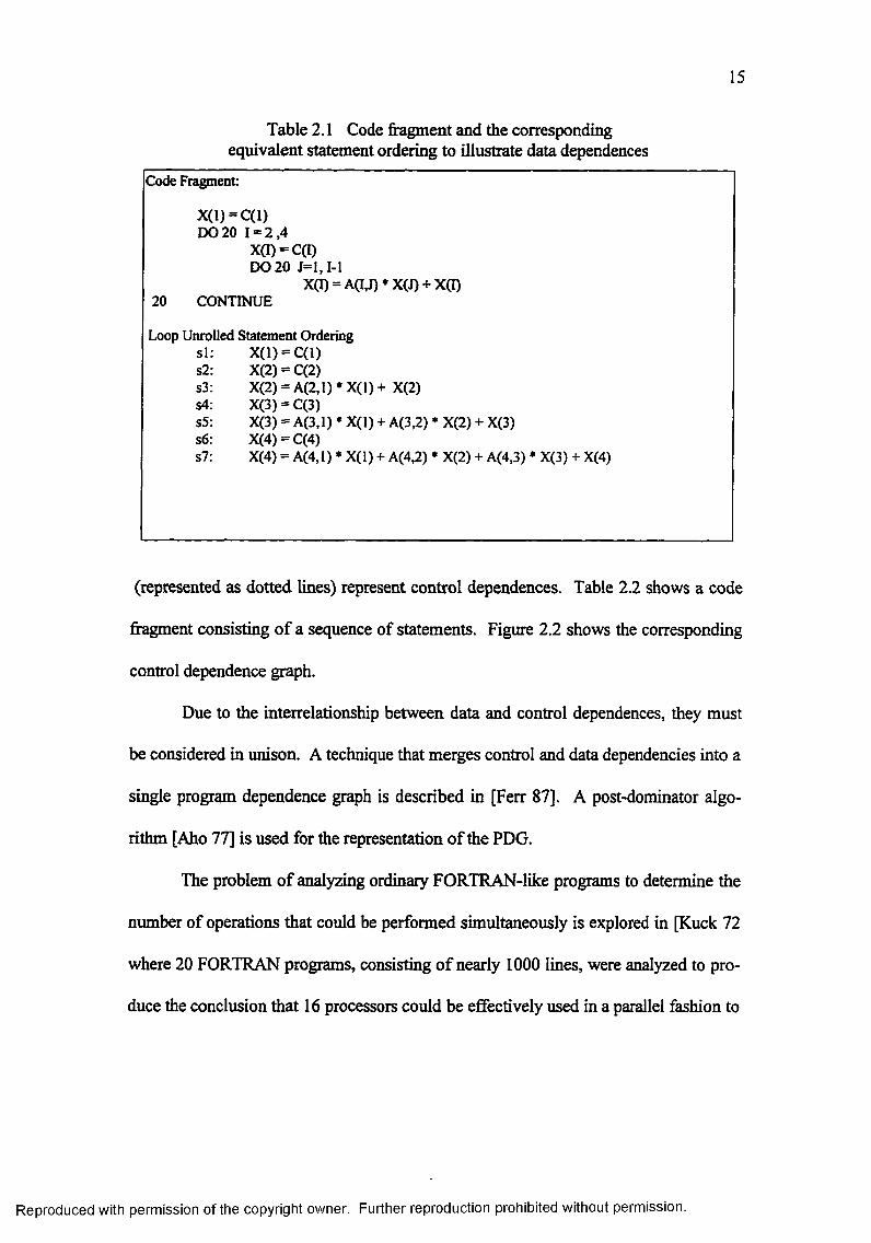
15
Table 2.1 Code fragment and the corresponding equivalent statement ordering to illustrate data dependences
Code Fragment:
X (l) = C (l)DO 20 1 = 2 ,4
X(I) = C(I)DO 20 J= l, 1-1
X(I) = A(I,J) * X(J) + X(D20 CONTINUE
Loop Unrolled Statement Orderings i: X(1) = C(1)s2: X(2) = C(2)s3: X(2) = A(2,l) * X (l) + X(2)s4: X(3) = C(3)s5: X(3) = A(3,l) * X (l) + A(3,2) * X(2) + X(3)s6: X(4) = C(4)s7: X(4) = A(4,l) * X(l) + A(4,2) * X(2) + A(4,3) * X(3) + X(4)
(represented as dotted lines) represent control dependences. Table 2.2 shows a code
fragment consisting of a sequence of statements. Figure 2.2 shows the corresponding
control dependence graph.
Due to the interrelationship between data and control dependences, they must
be considered in unison. A technique that merges control and data dependencies into a
single program dependence graph is described in [Ferr 87]. A post-dominator algo
rithm [Aho 77] is used for the representation of the PDG.
The problem of analyzing ordinary FORTRAN-like programs to determine the
number of operations that could be performed simultaneously is explored in [Kuck 72
where 20 FORTRAN programs, consisting of nearly 1000 lines, were analyzed to pro
duce the conclusion that 16 processors could be effectively used in a parallel fashion to
Reproduced with permission of the copyright owner. Further reproduction prohibited without permission.

16
Figure 2.1 Data dependence graph of the code fragment listed in Table 2.1
Reproduced with permission of the copyright owner. Further reproduction prohibited without permission.

17
Table 2.2 Code fragment to illustrate control dependences
si: A = Bs2: X = 2S3: if ( A.GT.1) thens4: Y = X * 20
endif
si
s2
s3
s4
Figure 2.2 Control dependence graph of the code fragment listed in Table 2.2
obtain speedup. The problem of interprocedural slicing — generating a slice of an en
tire program, where the slice crosses the boundaries of procedure calls — using a
“system dependence graph” is described in [Horw 90]. A survey of several architec
tures and compilation techniques based on the “critical dependence ratio” to exploit
parallelism in loops is presented in [Lilj 94]. The critical dependence ratio gives an
indication about the maximum speedup that can be achieved by unrolling loops.
The issues involved in generating a program dependence graph for reverse en
gineering research are emphasized in [Jack 94]. This model is particularly suited to
reverse engineering since it assumes the procedures (subroutines) to be modular and
Reproduced with permission of the copyright owner. Further reproduction prohibited without permission.

18
dependences to be fine-grained. Fine-grained dependences consider individual vari
ables rather than single program statements. Fine-grained dependences provide a way
to ensure that data structures are not neglected. In addition, almost all reverse engi
neering efforts are document intensive. Databases or knowledge bases are built that
categorize information that is extracted during the reverse engineering process. Hence,
it is essential that dependences be fine-grained for queries and reports to be compre
hensive.
A new model that takes into account the granularity of dependences and ex
tends the representation of the PDG is found in [Jack 94]. The model introduces the
notion of a site which conceptually relates to a statement in code where a state change
to a variable occurs. A site is a combination of the use and definition lists. Special
sites named entry and exit have only definition and use lists, respectively. For all other
sites, use list variable(s) are the variable(s) on the right-hand side and definition list
variable(s) are the variable(s) on the left-hand side. As an illustrative example of the
model a code fragment is listed in Table 2.3 and its corresponding PDG is shown in
Figure 2.3.
2.3 Knowledge-Based Analysis
The Programmer’s Apprentice project is a research effort to understand how
expert programmers conduct the activities of writing programs [Ric 88b]. The main
goal of the project is to apply techniques from the field of artificial intelligence to
automate the process of programming. Although program generators that produce ap
plications from specifications work well for narrow domains, fully automated
Reproduced with permission of the copyright owner. Further reproduction prohibited without permission.

19
Table 2.3 A code fragment to illustrate fine-grained dependences~ s l : A = B + C
s2: if(B.EQ.10)thens3: A = A + 20s4: end if
Use Lists
Site
Def Lists
ControlDependence
DataDependence
Figure 2.3 Program dependence graph of the code fragment listed in Table 2.3
Reproduced with permission of the copyright owner. Further reproduction prohibited without permission.

programming is not perceived as an immediate realistic goal [Ric 88a]. Consequently
the emphasis shifted from replacing programmers towards assisting programmers. In
order to provide intelligent support, the Programmer’s Apprentice project introduced
the notion of a cliche. A cliche is defined as a commonly used programming structure
for implementing higher level abstractions [Rich 90]. The cornerstone of efficient
programming is the use of sophisticated data structures and algorithms. Therefore,
both data structures and algorithms are represented as cliches. A formal graphical rep
resentation for programs and programming cliches is called the Plan Calculus [Ric
88b], which is a language-independent representation. The representation scheme of
Plan Calculus is a combination of flowcharts, dataflow schemas, and abstract data
types.
[Rich 90] describes a system, the Recognizer, that automatically identifies all
occurrences of a given set of cliches in a program and constructs a hierarchical de
scription of the program in terms of cliches. Recognizer identifies (recognizes) design
decisions in programs by first translating a program into the Plan Calculus and then
encoding the program as a flow graph. Finally, a design tree (the key output of the
Recognizer) of the program is produced by parsing the flow graph with the help of cli
ches.
Jarzabeck and Keam point out that even the simplest reverse engineering task
is a “knowledge-intensive” process. Accepting or rejecting decisions made during this
task needs the involvement of a domain expert. They describe the design of a generic
reverse engineering toolkit in [Jarz 95]. An approach to recognition of detailed pro
gramming plans (patterns) that combine top-down and bottom-up strategies are
Reproduced with permission of the copyright owner. Further reproduction prohibited without permission.

21
examined in [Quil 94]. The application of template-matching techniques from knowl
edge-based systems research in extrapolating the intended program function are
explored in [Hara 90].
Often problems associated with understanding a program can be attributed to
functional “interleaving” where a piece of code is responsible for accomplishing more
than one function [Ruga 95]. A formal definition of interleaving in terms of plans
[Rich 90] and a method to delocalize the is found in [Ruga 95].
One of the most important aspects in the design of knowledge-based programs
is the knowledge representation itself. The three most widely used knowledge repre
sentation schemes are rules, semantic nets, and frames [Wins 92].
2.4 Parallel Architectures
Conventional sequential computers are based on the von Neumann architec
ture. The sequential execution of programs on scalar data is an inherent characteristic
of von Neumann architectures. Large-scale numerical applications typically require
1012 to 1015 Flops (floating point operations) to achieve accurate results [Ston 94].
The sequential execution of large problems on conventional machines places serious
time limits. Researchers have developed techniques to improve the performance of
sequential computers using lookahead, multiple functional units, and pipelining [Hwan
93]. However, when solving large problems, the intrinsic sequential nature of these
computers results in a time-intensive solution.
An alternative to sequential computers is parallel computers. Parallel comput
ers can be broadly classified as either SIMD (single instruction stream over multiple
Reproduced with permission of the copyright owner. Further reproduction prohibited without permission.

22
data streams) or MIMD (multiple instruction stream over multiple data streams) [Flyn
72]. The processors in such systems communicate with each other via shared variables
in a common memory or through explicit message passing through an interconnection
network. The architectural structures of parallel computers are often biased towards
solving particular classes of problems. The characteristics of SIMD and MIMD com
puters are briefly described in the ensuing sections.
2.4.1 SIMD Computers
Hwang specifies an operational model of a SIMD computer by a 5-tuple [Hwan
93]:
P = <N, C, / , M, R>where
P is the SIMD model mder considerationN is the number o f processing elements (PEs)C is the set o f instructions executed by the control unit (CU)M is the set o f masking schemes to enable or disable subsets o f
PEsR is the set o f data-routing functions fo r inter-PE
communications
The operational model of a SIMD computers is shown in Figure 2.41. Each processing
element (PE) has its own processor and memory units. All PEs in a SIMD configura
tion execute the same instruction at each clock cycle. The control unit (CU)
broadcasts the instructions to the PEs which operate in lockstep. Only those PEs lo
cated in the active set, which can be user-defined by means of masking schemes, carry
out the instructions received from CU. The effectiveness of SIMD computer lies in
exploiting spatial parallelism in data parallel applications. The computational
1 Figures 2.4 and 2.5 adapted from [Hwan 93].
Reproduced with permission of the copyright owner. Further reproduction prohibited without permission.

23
parallelism in such applications ensues due to the physical parallel structure of the data
expressed in terms of array variables.
MasPar Computer Corporation MP-1 Family is a commercially available
SIMD computer. The number of PEs of MP-1 ranges from 1024 to 16,384 processors.
Each PE in MP-1 is a RISC processor with 16Kbytes of local memory. The intercon
nection network used in MP-1 is an X-Net mesh where each PE has 4 neighbors and a
mutistage crossbar connection [MasP 91]. Other representative SIMD computers in
clude Thinking Machines Corporation CM-2 and Active Memory Technology
DAP600 Family.
2.4.2 MIMD Computers
There are two major categories of MIMD computers, namely, shared-memory
mutiprocessors and message-passing muticomputers. The operational model of a
shared-memory MIMD computer is shown in Figure 2.5*. The processors in these
computers communicate with each other via shared variables in a common memory.
Both instructions and data are stored in the shared memory. Each processor is con
trolled by a separate control unit (CU) which issues the instruction stream. The data
stream for the operations identified by the instruction stream is obtained from the
shared-memory. In addition, each processor is responsible for its own I/O. An exam
ple of a shared-memory MIMD computer is Sequent Symmetry S-81 which consists of
30 processors connected by means of a bus.
Reproduced with permission of the copyright owner. Further reproduction prohibited without permission.

24
• • •
ControlUnit(CU)
PEn-i
ProcessingElement
PE,
Interconnection Network
Figure 2.4 An operational model of a SIMD computer
Reproduced with permission of the copyright owner. Further reproduction prohibited without permission.

25
DS
DS
ControlUnit(CU)
ProcessorUnit(PU)
ProcessorUnit(PU)
ControlUnit(CU)
SharedMemory
Legend:
IS: Instruction StreamDS: Data StreamI/O: Input and Output
Figure 2.5 Operational model of a shared-memory MIMD computer
Reproduced with permission of the copyright owner. Further reproduction prohibited without permission.

26
The operational model of a distributed memory MIMD computer is shown in
Figure 2.6. A MIMD computer can be specified by a 2-tuple:
M = <N, I>
where
M is the MIMD model under consideration
N is the number of autonomous computers (also referred to as nodes)
I is the interconnection network
Each node in a MIMD computer consists of a processor and local memory. In addition
I/O equipment may be attached to each node. Communication between nodes, to ex
change data, is carried out through explicit message-passing. An example of an
interconnection network used in these computers is a hypercube in which each node
occupies a vertex of multidimensional cube spanning along n dimensions, with two
nodes per dimension.
An example of a distributed-memory MIMD computer is Intel iPSC/860. One
configuration of iPSC/860 has 23 = 8 nodes. The nodes are interconnected in a hyper
cube where each node has 3 neighbors. Other representative distributed-memory
MIMD computers include nCUBE/2 6480 and Parsys Ltd. SuperNodelOOO.
2.5 Tool Sets and Case Studies
A set of tools called parallel Reverse Engineering ToolSet (pRETS) which
supports semi-automated conversion of FORTRAN programs into Strand foreign lan
guage kernels is described in [Harr 93]. Strand is a concurrent programming language
based on Prolog. Among the various components of pRETS is a FORTRAN analyzer
Reproduced with permission of the copyright owner. Further reproduction prohibited without permission.

27
LocalMemory
LocalMemory
LocalMemory
Processor Processor• • •
Processor
LocalMemory
LocalMemory
Processor InterconnectionNetwork
Processor
• •
LocalMemory
LocalMemory
LocalMemory
Processor Processor• • •
Processor
Figure 2.6 Operational model of a distributed-memory MIMD computer
Reproduced with permission of the copyright owner. Further reproduction prohibited without permission.

28
“fa” which builds the general knowledge base of a program in terms of program facts,
store facts, and label facts. Using these facts, another component “dataflow” converts
the program into a special-purpose dataflow knowledge base. Finally, using the in
formation produced by “dataflow”, a set of Prolog rules transform the subroutines of
the program into Strand foreign language kernels.
A case study that documents the reverse engineering and reengineering of a
twenty year old system is presented in [Kara 95]. The reverse engineering tools were
used mainly to “filter” the source code to retrieve the control structure of the program.
Restructuring and dependence analysis were done manually. Subsequently, the origi
nal system was reengineered into a PVM based parallel implementation.
In the same spectrum, parallelizing compilers migrate code from the uni
processor to parallel processing environments by performing code-to-code transfor
mations. For example, Parafrase-2 is a high-performance multilingual restructuring
parallelizing compiler [Hagh 91]. The main thrust in parallelizing compilers is elabo
rate dependence analysis, program restructuring, and program transformations.
Parallelizing compilers are architecture specific in that program restructuring is aimed
at utilizing the available hardware resources on a particular architecture.
2.6 Relevance to the Dissertation
Legacy systems need to be revamped to adapt to current computing trends.
Program comprehension and design recovery are primary issues involved in the mi
gration of these systems to new platforms. Reverse engineering research reveals that
there is high potential for program comprehension and design recovery. Although
Reproduced with permission of the copyright owner. Further reproduction prohibited without permission.

29
there is widespread research to reverse engineer legacy systems for maintenance, com
ponent recovery, and redocumentation [Edwa 93] [Ning 94], very few initiatives exist
to migrate legacy systems to parallel platforms using reverse engineering techniques.
The research presented in this dissertation is motivated largely due to previous work in
the migration of FORTRAN code by [Harr 93]. While case studies described in [Kara
95] are useful, they do not offer automated solutions to help analyze systems in a gen
eral way.
Research in the area of dependence analysis may be applied to understand de
pendences in a large programs. Models such as the one described in [Jack 94] are
particularly suited for reverse engineering research. The potential to exploit parallel
and distributed system advantages is another reason to migrate legacy systems. Since
the reverse engineering process is “knowledge-intensive”, research in the field of
knowledge-based program analysis may be applied for meaningful and intelligent
analysis of information present in current legacy systems.
An explicit design recovery step is absent in parallelizing compilers. Since
legacy systems usually lack explicit documentation, the absence of a design recovery
procedure is a serious limitation that hinders understandability and maintainability of
the original system as well as the parallelized version.
Hence a methodology that provides benefits for the migration process and the
maintenance process is essential. This dissertation presents a methodology which is
aimed at providing systematic migration of sequential code using principles, methods,
and techniques at the intersection of reverse engineering, dependence analysis, and
knowledge-based analysis.
Reproduced with permission of the copyright owner. Further reproduction prohibited without permission.

The relevance of the related research presented in this chapter to the disserta
tion is summarized in Table 2.4. The research presented in this dissertation is listed in
the first column of Table 2.4. Other columns of Table 2.4 represent previous work
[Kara 95] [Harr 93] [Hagh 91]. The rows represent the various characteristics that are
considered.
Reproduced with permission of the copyright owner. Further reproduction prohibited without permission.

31
Table 2.4 Related reverse engineering research
RETK BNDPKGfKara951
pRETS [Harr 931
Parafrase-2[Hagh91]
DesignRecovery
Comprehensiveand
Automated
Manual Semi-Automated No explicit design recovery procedure
ProgramDependency
Analysis
ElaborateAutomated
Manual Manual RigorousElaborate
Automated
Knowledge-Based
Approach
ElaborateAutomated
None ElaborateAutomated
None
Restructuring None Manual ManualRigorousElaborateAutomatic
Potential for Reengineering
Yes Yes Yes Yes
Reproduced with permission of the copyright owner. Further reproduction prohibited without permission.

Chapter 3
A Reverse Engineering Methodology for Design Parallelization
This chapter describes a methodology for the migration of code from the uni
processor to the parallel processing environments. The methodology defines a set of
phases that serve to systematically approach the problem of code migration. A set of
processes are defined for each phase. The processes within the each phase address the
issues of design recovery, dependence analysis, and knowledge-based program com
prehension as put forth in Chapters 1 and 2. The processes of each phase represent a
different approach to the problem of code migration to those employed by parallelizing
compilers. Benefits of the methodology are increased overall comprehensibility and
improved maintainability of the existing system.
In this chapter, we first present an overview of the three-phase approach of the
methodology. Central to the conceptualization of the methodology is the source lan
guage used to write existing systems. We therefore present issues related to the
selection of a source language for the purposes of establishing a working model for
the methodology. Next, we describe each phase and the processes of each phase in
detail. One of the unique features of the methodology is the incorporation of auto
mated intelligent support in the migration process. Issues pertaining to the selection of
a knowledge-based tool are also discussed.
32
Reproduced with permission of the copyright owner. Further reproduction prohibited without permission.

33
3.1 Overview of the Methodology
The three main phases of the migration methodology are: Analysis, Synthesis,
and Transformation. The three phases represented as a cascaded architecture are
shown in Figure 3.1.
The primary objective of the Analysis phase is to extract the original design
description of the existing system. The purpose of this phase is to help cope with the
complexity of existing systems. Representation of the sequential design description is
also one of the important processes of this phase. Large programs, comprised of sev
eral modules, typically run over many thousands of lines of program code. According
to [Chik 90] and [Ning 94], legacy systems are both voluminous and complex and can
only be combated with enough automated support. Therefore, the Analysis phase must
be supported by tools with a high degree of automated support to combat complexity.
The Synthesis phase combines the design description (produced by the Analy
sis phase) associated with the various modules to arrive at a holistic view of the
design. Representation of the program dependences in the form of a Program Depend
ence Graph (PDG) is one of the main processes of this phase. Since a large program
potentially has several program dependences, the Synthesis phase must also be sup
ported by tools for automated support.
Finally, the Transformation phase is comprised of processes that require
knowledge-based analysis of the information produced by the Analysis and Synthesis
phases. Design recommendations for parallel environments are the key output of the
Transformation phase. Tools for this phase must be equipped with support for knowl
edge-based representation, search, and analysis.
Reproduced with permission of the copyright owner. Further reproduction prohibited without permission.

34
SequentialSystems
Analysis
Synthesis
Transformation
Parallel Design Recommendations
Figure 3.1 Cascaded architecture of the 3-phase migration methodology
Reproduced with permission of the copyright owner. Further reproduction prohibited without permission.

35
3.2 Source Language
FORTRAN, which stands for FORmula TRANslation, is a high-level language
that is used to solve problems in science and engineering. The language is now about
40 years old. FORTRAN was developed for the IBM 704 computer and the first com
piler was released in April 1957. As computer hardware improved, the FORTRAN
language continued to evolve with new refinements and extensions. FORTRAN IV
was the fourth version developed between 1960-19962 and was the standard version
until 1978 [Seba 93]. Because of the proliferation of FORTRAN, portability of pro
grams across different machines became a problem. In order to achieve uniformity,
the American National Standards Institute (ANSI) published FORTRAN standards.
As extensions for the standard version continued to be developed, it became apparent
that these extensions should be incorporated into a new standard. The updated ANSI
FORTRAN standard was called FORTRAN-77 [ANSI 78]. Several versions of FOR
TRAN have been released since FORTRAN-77, with the most recent being
FORTRAN-90.
FORTRAN-77 is a high-level language which provides sequential, selective,
and iterative structures allowing operations on data types of integer, real, complex,
character, and logical. Features of FORTRAN-77 include implicit data typing, the
COMMON statement, and the EQUIVALENCE statement. Implicit data-typing was
the only mechanism available in the early versions of FORTRAN. Variables whose
names begin with I, J, K, L, M, and N are implicitly integer type, and all others are im
plicitly real. Later versions of FORTRAN included the IMPLICIT statement which
identifies a group of variables whose names begin with a certain letter to be of a
Reproduced with permission of the copyright owner. Further reproduction prohibited without permission.

36
particular type. The COMMON statement establishes a specified portion of memory
in which data can be stored and retrieved directly by each of the program modules.
The COMMON statement has two forms: unlabeled and labeled. While unlabeled
COMMON statement establishes an unnamed reserved block of memory, labeled
COMMON statements establish a named reserved block of memory. Labeled COM
MON statements are used in situations where it may be desirable to share one set of
variables among some program modules and to share another set among other program
modules. Consequently, only one unlabeled COMMON statement is allowed per pro
gram, whereas multiple labeled COMMON statements are allowed. The
EQUIVALENCE statement provides for the association of variables and arrays, in the
same program unit, to share the same memory locations. The EQUIVALENCE state
ment was once of immense use in reducing the memory requirements of programs, as
it allows large arrays to share the same memory locations. However in recent years
EQUIVALENCE statements are used infrequently because memories have become
less expensive.
Although the use of FORTRAN-77 is widespread, it has several undesirable
features: (i) with the absence of constructs for pre-test and post-test, GOTOs are used,
potentially introducing severe readability problems, (ii) identifiers are restricted to 6
characters which is also a source for poor readability, (iii) type checking between ac
tual parameters in a subroutine call and the formal parameters in subroutine definition
is not done, (iv) recursion is not allowed, (v) separate compilation is not allowed, and
(vi) aliasing is caused by the use of COMMON and EQUIVALENCE statements.
Since each of the above mentioned features is undesirable for programming in the
Reproduced with permission of the copyright owner. Further reproduction prohibited without permission.

37
large and because equivalent efficiency can be obtained by using other programming
languages, the benefits gained by the continuation of use of FORTRAN-77 are ques
tionable. Specifically, the introduction of the object-oriented paradigm and languages
such as C++ pose challenges to FORTRAN-77.
FORTRAN-90 which is the “modernized” version of FORTRAN-77, borrowed
many programming language concepts from contemporary block structured languages
while retaining its original structure. Some of the noteworthy features are recursive
procedures, a built-in collection of functions for array operations, dynamic allocation
and deallocation of arrays, pointers, control statements like CASE for multiple selec
tion, and abstract data types similar to those of Ada and Modula-2 [Seba 93].
The High Performance Fortran Forum was founded in 1992 to “improve the
performance and usability of FORTRAN-90 for computationally intensive applications
on a wide variety of machines including massively parallel SIMD and MIMD systems
and vector processors.” Among the various extensions considered were data distribu
tion, parallel statements, extended intrinsic functions and standard library, extrinsic
procedures, parallel I/O statements, and changes in sequence and storage association.
One goal of the forum is to provide a High Performance Fortran (HPF) programming
model for software developers to write parallel programs for distributed-memory sys
tems. Programs can be written in a single-program, multiple-data (SPMD) style.
Information about desired locality or distribution can be provided by annotating the
code with HPF data-mapping directives. The resultant code can then be compiled us
ing an architecture-specific compiler [Love 93].
Reproduced with permission of the copyright owner. Further reproduction prohibited without permission.

38
The reasoning behind the selection o f FORTRAN-77 as the source language
for the migration methodology is twofold. Firstly, because of its domain of applica
tion and the length of existence, FORTRAN represents a large portion of software
currently in use. Secondly, FORTRAN-77 was chosen because it represents the origi
nal version of FORTRAN for which standards exist [Holo 83].
3.3 Analysis Phase - Abstraction o f the Original Design Description
In this section, we describe the Analysis phase shown in Figure 3.1 in detail.
The processes of this phase are: (i) Code Assessment, (ii) Code Re-structuring, (iii)
Code Segmentation, (iv) Code Parsing, and (v) Design Aggregation. Figure 3.2 shows
a graphical layout of the processes mentioned above.
33.1 Code Assessment
Before attempting to realize the sequential design description of the existing
system, it is essential to assess the code associated with the existing system. Metrics
information enables objective assessment of the software for reliability and maintain
ability. This process provides metric information like number of lines of code
(executable, commented, and blank) and complexity information like McCabe’s cy-
clomatic complexity. The metric information helps software managers to get an initial
“feel” for the existing system. In addition, the metric information is useftd in the
reengineering process by giving software engineers access to the in-code-
documentation, if any, of the existing system. One of the reengineering tasks is the
Reproduced with permission of the copyright owner. Further reproduction prohibited without permission.

39
Existing System
CodeAssessment
CodeRe-Structuring
CodeParsing
DesignAggregation
CodeSegmentation
Sequential Design Description
Figure 3.2 Processes of the analysis phase
Reproduced with permission of the copyright owner. Further reproduction prohibited without permission.

40
modification of existing systems to add new functions or capabilities. In such situa
tions, one important issue to be resolved is the impact of side-effects. The availability
of in-code-documentation helps to assess specific changes to variables that have a po
tential to introduce a side-effect.
3.3.2 Code Re-Structuring
A major problem with some old programs is unstructured code, which the
computing community refers to as “spaghetti code.” The common element which
causes code to become unstructured is unconditional branching using GOTO state
ments. In some languages, especially FORTRAN-77, GOTO statements are the only
way to provide control in certain situations. However, frequent use of GOTO state
ments in large programs affects readability, understandability, and maintainability.
To successfully recover the design information form existing systems, the as
sociated code must be structured. A set of axioms exist in the literature for replacing
GOTOs with appropriate loop or alternation constructs [Dijk 76] [Marc 86].
Dijkstra’s D-structures can be used to restructure code.
A D-structure is defined as one of the following:
(i) a basic action — an assignment statement, a procedure call, or an input-output
statement,
(ii) a sequence of D-structures,
(iii) a conditional structure of the form
if <eondition> then<d-struct[> else <d-struct2> else
endifwhere, d-structjand d-struct2 are D-structures, and
Reproduced with permission of the copyright owner. Further reproduction prohibited without permission.

(iv) an iterative structure of the form
while <Condition> loop <d-struct>
end loopwhere d-struct is a D-structure.
Boehm and Jacopini have proved that any program can be written using only D-
structures [Marc 86]. We therefore assume that any program can be written com
pletely using D-structures.
3 3 3 Code Segmentation
In order to analyze the source code associated with a large program, the pro
gram must be split into segments. Meaningful segmentation of the source code is
based on the syntax and semantics of the underlying programming language. Also, the
segmentation activity is designed in way that essentially culminates in the design de
scription of the source code. For example, a FORTRAN-77 program consists of a
main program, zero or more subroutines, and zero or more user-defined function mod
ules. These modules collectively define the design of the program. Therefore, the
code segmentation process of the Analysis phase employs a segmentation scheme that
separates the source code of a FORTRAN-77 program into individual modules. Addi
tional features of the segmentation process includes processes for removing visual
sugar like tabs, indents, and leading spaces associated with code.
The methodology uses the object-oriented paradigm for the design of the code
segmentation process. Each module in the program, the main program, subroutines,
and user-defined functions, is considered to be an object. Attributes of each object
includes the source code pertinent to the module. The keywords “PROGRAM”,
Reproduced with permission of the copyright owner. Further reproduction prohibited without permission.

42
“SUBROUTINE”, and “FUNCTION” in the source code identify the beginning of a
module and the keyword “END” identifies the end of a module. For syntactically cor
rect programs, all lines of code after the keyword “END” of one module, say Module-i,
and the beginning of the next module, say Module-j, are non-executabie lines. These
non-executable lines serve as comments or in-code documentation. After observing
several programs, we determined that the non-executable lines of code after Module-i
ends and before Module-j begins are usually associated with Module-j. Examples of
associations include names of authors), meaning of variable name, and description of
algorithms used to implement a module. Hence the code segmentation process associ
ates these non-executable lines of code with Module-j. An algorithm for the code
segmentation process is presented in Table 3.1
A detailed description of the object-oriented design of the various processes of
the Analysis phase are described in Chapter 4.
3.3.4 Code Parsing
The code parsing process analyzes the code associated with individual modules
identified by the code segmentation process. An issue related to the code parsing ac
tivity is to determine whether or not the programming language allows reserved words
in the language design. If the language allows reserved words, then these words may
be utilized for the parsing activity. In languages such as FORTRAN-77, where there
are no reserved words, all keywords can be assumed to be reserved words.
Reproduced with permission of the copyright owner. Further reproduction prohibited without permission.

43
Table 3.1 Algorithm for code segmentation
II Algorithm for Code Segmentation
M ainProgram program;Subroutine subs[M];Function fims[N]; int su b n o = 0; int fim no = 0; char **lines; int line_no = 0; int k = 0; char *token; int type;
boolean flag;
do while NOT EOF {Read lines[line_no]; line_no++;
}
do while ( k < = line_no) { Remove_Visual_Sugar ( lines[k]);
extra
token = Extract_First_Token ( lines[k]);
if ( token = "PROGRAM") {Copy lines[k] into program object; type= 1;
}else if ( token = "SUBROUTINE" ) {
Copy lines[k] into subs[sub_no] object; type = 2;
}else if ( token == "FUNCTION" ) {
Copy lines[k] into fims[fun_no] object; type = 3;
}k++;
flag = TRUE;
do while ( flag = TRUE) { Remove_Visual_Sugar ( lines[k]); token = Extract_First_Token ( Iinesfk] );
// Declare Main Program object // Declare M Subroutine objects
// Declare N Function objects // Index of next subroutine object // Index o f next function object // Physical lines in source code // Index o f next line to be read // Index o f the next line to be processed // Declare token to be o f type string // Type =1 for Main Program, 2 for // Subroutine and 3 for Function // Flag is either TRUE or FALSE
// Read line from file and increment // the index
// This function removes indents, tabs, and
// spaces in !ines[k]// This function returns the first token of // lines[k]
(table con’d.)
Reproduced with permission of the copyright owner. Further reproduction prohibited without permission.

44
switch ( type) {
case 1: Copy lines[k] into program object; break;
case 2: Copy Iines[k] into subs[sub_no] object; break;
case 3: Copy lines[k] into funs[fiin_no] object; break;
}
if ( token = "END") { switch (type) {
case 2: sub_no++;break;
case 3: fun_no++; break;
}
flag = FALSE;}
k++;}
}
The code parsing process is the main activity in the realization of an abstrac
tion of the original design description. The code parsing process relies on the syntax
and semantics of FORTRAN-77. Keywords play a major role in the abstraction of the
design description. Keywords in conjunction with the grammar of FORTRAN-77 de
fine the syntactic constructs of a program. In addition, keywords are useful in
extracting semantically related pieces of code. For instance, in FORTRAN-77,
Reproduced with permission of the copyright owner. Further reproduction prohibited without permission.

45
subroutine calls are preceded by the keyword “CALL” and explicit declaration of vari
ables are preceded by data-type keywords like “INTEGER” and “REAL”. Therefore
the parsing process uses keywords to define the process and data models by using
techniques like program slicing [Weis 84]. Slicing is performed at various levels:
statement, construct, and block. The parsing process provides the design representation
of the original program and includes call graphs, structure charts, hierarchical dia
grams, local and non-local variable description, and state change information. The
synopsis of the information recovered at the end of the parsing activity is as shown in
Figures 3.3, 3.4 and Tables 3.2 and 3.3. An algorithm for the code parsing process is
shown in Table 3.4.
3.3.5 Design Aggregation
Once the design associated with the individual modules is obtained, the overall
design of the program is obtained by combining information extracted from individual
modules. A global call-graph that shows the interactions between the various mod
ules is constructed. Consequently, tools designed for this phase should
provide scope to generate graphical representations. These representations will aid in
the overall comprehensibility and improved maintainability of the source system. An
algorithm for the design aggregation process is shown in Table 3.5.
3.4 Synthesis of the Sequential Design Description
In this section, we describe the Synthesis phase shown in Figure 3.1. The
processes of this phase are (i) Module Dependence Analysis and (ii) Synthesis of the
Program Dependence Graph (PDG). The design information recovered in the Analysis
Reproduced with permission of the copyright owner. Further reproduction prohibited without permission.

46
Main
Subi
Figure 3.3 Representation of a call graph
Sub
Main
Legend: Data
Control
Figure 3.4 Representation of a structure chart
Reproduced with permission of the copyright owner. Further reproduction prohibited without permission.

47
Table 3.2 Representation of local and non-local variable description
ModuleName
VariableName
DataType
Is Variable an Array
Dimensions if Array
Scope of the
Variable
• INTEGER• REAL• DOUBLE
PRECISION• CHARACTER• LOGICAL
• Yes• No
• Local• Global• Formal
Table 3.3 Representation of state change information
ModuleName
State ChangeVariableName
Variable Names involved in the State Change
Type SemanticNature
• Simple• Iterative• Conditional
• Direct Assignment Statement
• Assignment via a subroutine call
Reproduced with permission of the copyright owner. Further reproduction prohibited without permission.

48
Table 3.4 Algorithm for the code parsing process
// Algorithm for code parsing.// This algorithm is used to parse the source associated with each component
M ain (){
ComponentExtract_Calls ( ) ;ComponentExtract_Variable_Description () ; Component.Extract_State_Changes () ;
}
Component:: ExtractCalls ( ){
int k = 0; // Index o f next line to be parsedchar ‘ token; // String that holds first token of a linechar ‘rest; // String that holds the rest o f the line
do while ( k < MAX_LINES_IN_COMPONENT) {token = Extract_First_Token ( Component. Iinesfk]); rest = Rest ( Component.lines[k]);
if ( token = “CALL” )Extract_Actual_Parameters ( re s t);
Save_Subroutine_Call_Infonnation;
}
Component::Extract_VariabIe_Description ( ){
int k = 0; // Index o f next line to be parsedchar ‘ token; // String that holds first token o f a linechar ‘ rest; // String that holds the rest o f the line
do while ( k < MAX_LINES_IN_COMPONENT) {token = Extract_First_Token ( Component.Iines[k]); rest = Rest ( Component.lines[k]);
if ( token = “REAL” or token = “INTEGER” ortoken = “DOUBLE” or token = “PARAMETER” or token = “CHARACTER” )
Extract_VariabIes ( rest); else if ( token = “COMMON” ) {
if ( Iabeled_COMMON = T ru e) {Extract Label Name (re s t) ;
}
(table con’d.)
Reproduced with permission of the copyright owner. Further reproduction prohibited without permission.

49
ExtractCommonVariables ( res t);}Save_Subroutine_CalI_Information;
}}
Component::Extract_State_Changes ( ){
int k = 0; // Index o f next line to be parsedchar *token; // String that holds first token o f a line
do while ( k < MAX_LINES_IN_COMPONENT) {token = Extract_First_Token ( Component.lines[k]);
if ( token != Keyword)Process_Assignment ( Component.Iines[k]);
else if ( token = “READ”)Process_READ ( ComponenUines[k]);
else if ( token = “IF ’ ) {Process_IF ( Component.lines[k]);BuiId_IF_List ( Component.lines[k]);
}else if ( token = “DO” )
Build_IF_List ( Component.Iines[k]);}
}
Component: :Process_Assignment ( char *Passed_Line){
char *L_Vaiue; char *R_VaIue;
L_Value = Extract_L_VaIue ( Passed_Line);R_VaIue = Extract_R_Value ( PassedL ine); Extract_State_Change_Variable ( L_VaIue);ExtractFunctionC alls ( R_Value)Extract_RHS_V ariables ( R_Value)
Save_State_Change_Attributes () ;}
Reproduced with permission of the copyright owner. Further reproduction prohibited without permission.

50
phase is used in the Synthesis phase. Research in the area of dependence analysis, as
outlined in Chapter 2, has concentrated on determining dependences directly from
code. Parallelizing compilers also determine dependences directly from code. In con
trast, the processes defined in the Synthesis phase focus on the analysis using design
representations recovered in the Analysis phase. The output of the Synthesis phase is
the Program Dependence Graph (PDG) which makes explicit both data and control
dependences. Figure 3.5 shows a graphical layout of the processes of the Synthesis
phase.
One major issue in the design of processes of the Synthesis phase is the selec
tion of an appropriate PDG representation. The choice of the PDG representation
depends on the desired granularity of the dependences. For reverse engineering re
search, the model proposed by [Jack 94] is appropriate because of its clean
representation scheme. The model in [Jack 94] views procedures as modular and de
pendences as fine-grained.
3.4.1 Module Dependence Analysis
The objective of the module dependence analysis is to determine the data and
control dependences of each module identified by the Analysis phase. The state
change information recovered in the Analysis phase is used as a starting point for this
process. Using the notation defined in [Jack 94], sites are built for each state change.
By definition, a site conceptually relates to a state change to a variable in the state
change information table (Table 3.3). A site is a combination of use lists and defini
tion lists. Special sites named entry and exit have only definition and use lists,
Reproduced with permission of the copyright owner. Further reproduction prohibited without permission.

51
Table 3.5 Algorithm for design aggregation
// Algorithm for Design Aggregation
// Definition o f link struct link
{// one element o f a list
char *component_name; // Name o f the moduleshort num_children; // Number o f childrenchar **names_of_children; // Names o f childrenlink *next; // Pointer to next link
// Definition o f class LinkList class LinkList {
private:link * first;
// A List o f Links
// Pointer to first link
public:LinkListO // No-argument constructor{
first = NULL; // Initialize first link to NULL}
Build_Global_Call_GraphO;
DispIay_Global_Call_GraphO;
};
//
mainO{
// Member funcion which builds // the Global Call Graph
// Member funcion which // displays the Global Call Graph
Main Algorithm
LinkList 11; // Create An Instance "U" o f the Class LinkList
ll.Build_Global_Call_GraphO; // Call to member function
ll.Display_Global_Call_GraphO; // Call to member function
(table con’d.)
Reproduced with permission of the copyright owner. Further reproduction prohibited without permission.

52
// Memeber Function Build_Global_CalI_GraphLinkList::Build_G!obai_CaII_GraphO{
char *name_of_curr_comp; // Name o f the Current Componentchar ‘ comps; // Names o f the Components called by
// Component 'nam eof^currcom p' int num; // Number o f Components called by
// Component 'name_of_curr_comp'
For All Components in the Design {
name o f curr comp = Get Name o f the Component;comps = Get Names o f all components called by 'name_of_curr_comp';num = Get Number o f all components called by 'name_of_curr_comp';
// Create New Link
link ‘newlink = new link;
// Add Information to Link
newlink->component_name = name_of_curr_comp; newIink->names_of_children = comps; newlink->num_children = num;
newlink->next = first;
first = newlink;}
}
// Memeber Function Display_Global_Call_Graph LinkList::Display_GIoba 1 CallGraphO {
link ‘ current = first;
while ( current != NULL) {Print current->component_name;Print current->num_children;Print All current->names_of_chiIdren;
current = current->next;
Reproduced with permission of the copyright owner. Further reproduction prohibited without permission.

53
Sequential Design Description
Module D Ana
rependencelysis
Synthesis of the PDG
; Program Dependence Graph (PDG) j
Figure 3.5 Processes of the synthesis phase
respectively. For all other sites, use list variable(s) are the variable name(s) involved
in the state change and the definition list variable(s) are the variable name(s) to which
the state change is occurring. In other words, use list variable name(s) correspond to
the third column and definition list variable name(s) correspond to the second column
of Table 3.3 respectively. Some programming language issues are in order here.
Since FORTRAN allows only one variable to be defined in an assignment statement,
only one definition list variable for every site is defined. However, we modified this
definition slightly to include the loop variable in the definition list in the site for the
last state change in the loop scope. The meaning of the special symbols, defined in
Reproduced with permission of the copyright owner. Further reproduction prohibited without permission.

54
[Jack 94], are retained in the notation. The special symbols are “t , a temporary that
holds the result of a conditional test, y, which represents a constant, and e, which
stands for ‘execution’” [Jack 94]. In order to obtain a comprehensive summary of the
control dependences, we have extended the meaning of x to include xT (true part of
the conditional test) and xF (false part of the conditional test). The original notation
defined in [Jack 94] with modifications and extensions as applied to the state change
information is described below:
StCh = State Change = {LV, RVs, Type}LV = Left Hand Side Variable RVs = Right Hand Side Variable(s)Type = {Simple, Iterative, Conditional}UL = Use Lists = StCh.RVs u{y, s}DL = Definition Lists = {StChs.LVs uLoopVariable u {t, tT,tF}}Site = (UL xDL} u {entry, exit} rx = {r, tT, tF}
Three relations which represent the dependences are fd for dataflow dependences
(forward flow), Id for loop dependences (backward flow), and cd for control depend
ences. Using the notation described above, the three relations are defined as:
fd c { ((x , i), (y, j)) I x e DL A y e UL a x = y a i ,j e Site A i <j}Id c{((x, i), (y,j)) I x e DL A y eU L a x — y a i ,j eS ite A i > j } cd c{((e , i), (Tx, j)) / e eU L a t x e DL a i ,j eSite A i < j}
Since in FORTRAN, it is possible to declare variables implicitly, all variables defined
at the entry are only the variables that are explicitly declared. All the variables used at
the exit are both variables that explicitly and implicitly defined.
We define the term abstract site for every module except the main program.
An abstract site’s use list variable(s) are the non-local variables of the module which
Reproduced with permission of the copyright owner. Further reproduction prohibited without permission.

55
include formal parameters (if any) and COMMON variables. The definition list vari
ables of the abstract site are the same non-local variables to which a state change
occurs within the module. Abstract sites are useful in determining whether or not two
modules can be parallelized. An algorithm for the creation of sites is listed in Table
3.6. An algorithm for computing the data dependences from site information is pre
sented in Table 3.7. An algorithm for computing the control dependences from site
information is given in Table 3.8.
3.4.2 Construction of the PDG
After the dependence analysis is carried out on each module, the results of the
analysis is combined to form the PDG. The call graph is used as the starting point to
build the PDG. Since the call graph is a tree representation, the PDG is built starting
at the leaves and moving to the root. The outcome is that the PDG is essentially the
call graph but with explicit dependence analysis. Calls made to subroutines (or mod
ules) from a given subroutine are replaced by the called subroutine’s abstract site.
Since a large program might consist of several dependences, tools designed for
this activity should be capable of generating and displaying graphical representations.
Appropriate color coding schemes should be employed to differentiate data and con
trol dependences. Thus, the processes of the Synthesis phase combine the dependence
analysis of all the modules in the design to construct an overall view of the existing
system.
Reproduced with permission of the copyright owner. Further reproduction prohibited without permission.

56
Table 3.6 Algorithm for creating sites and their use and definition lists
// Algorithm for Creating Sites and their Use and Def Lists Main
Refers Sts[i] for every Sts[i] do
if Sts[i].Category is NULL call Insert_Into_Def_List(i); call Separate_RHS_and_Insert_Into_Use_List(i);
else // Conditional detected either DO or IF int retum code; // return code is 1 if Assignment
// Statement to be processed and is 0 if NOT
retum_code = call Ascertain_Type_of_Conditional_and_Build_Tau_Sites(i); if retum_code is 1
call Insert_Into_Def_List(i); call Separate_RHS_and_Insert_Into_Use_List(i);
end if end if
end do End Main
proc int Ascertain_Type_of_Conditional_and_Build_Tau_Sites(int i) int j = 0; // To keep track o f Sts[i].Category char by charint number;char temp[80]; int t = 0;
while isdigit(Sts[i].Category[j])j++;
while (Sts[i].Category[j] !=temp[t++]= Sts[i].Category[j-H-]; temp[t]=,\0’;
number = atoi(temp); j++; // skip *
char rest[80];int r=0;
while (Sts[i].Category[j] != I\0') { rest[r++] = Sts[i].Category[j-H-];
rest[r] = 'VO';
call Build_Tau_Sites(i, number, rest));
if(rest[0] == T ) return 1;
else return 0;
end proc
(table con’d.)
Reproduced with permission of the copyright owner. Further reproduction prohibited without permission.

57
proc BuiId_Tau_Sites(int i, int number, char *rest) char ch;int next_number;
ch = restfO];
switch(ch) {case T)': next_number = Iteratives[number].Prev_Id;
break;case T , V : next_number = Conditionals[number].Prev_Id;
break;default: break;
}
char *p; char *new_rest; char copy_of_rest[80]; char str(3];
sprintf(str,"%c\0", ch); strcpy(copy_of_rest, rest); p = strtok(copy_of_rest, str); new_rest = strtok(NULL, "\0"); if (new_rest)
call Build_Tau_Sites(i, next_number, new_rest);else {
switch(ch) {case T)': if (number >= do_lists_built_so_far) {
call Build_DO_Tau(i, number); do_lists_buiIt_so_fan-+;
}break;
case T : if (number >= if_lists_built_so_far) { call Build_EF_Tau(i, number); if_lists_built_so_far++;
}break;
default: break;}
}
end proc
(table con’d.)
Reproduced with permission of the copyright owner. Further reproduction prohibited without permission.

58
proc Build_DO_Tau(int i, int number)
call Insert_IntoJDef_List(i); if (atoi(Iteratives[number].Intial_Value) != 0)
strcpy(Sites[num_sites].uls[num_uls++].name, Iteratives[number].Intial_Value)
strcpy(Sites[num_sites].uIs[num_uls++].name, "*E*") num_sites++;
char ui[8];sprintf[ul, "DO [%d]\0", number); strcpy(Sites[num_sites].dls[num_dIs++].name, "*Tau*") strcpy(Sites[num_sites].uls[num_uls++j.name, ul) num_sites++;
end proc
proc BuiId_IF_Tau(int i, int number)
char ul[8];sprintf(ul, "IF [%d]\0", number); strcpy(Sites[num_sites].dls[num_dls++].name, "*Tau T*") strcpy(Sites[num_sitesi.dIs[num_dls++j.name, "*Tau F*") strcpy(Sites[num_sites].uIs[num_uIs++j.name, ul) num_sites++;
end proc
Table 3.7 Algorithm for computing data dependences
// Algorithm for computing Data DependencesMainfor all sites identified by s starting from 1 {
for each Use List variable identified by u starting from 0 to < (num_uls-l) { int found = 0; if uls[u].name is 0 or *Gamma*
do nothing else if uls[u].name is DO[x]
Process_DO_DataDep(s) else if uls[u].name is IF[y]
Process_IF_DataDep(s)Check(u, name, s);
}}
End Main
(table con’d.)
Reproduced with permission of the copyright owner. Further reproduction prohibited without permission.

59
proc Check_Name(int u, char *name, int s){
fo r(s’=s - 1; s’=0; s’- ) { for(d=0;d<Sites[s’].num_dls;d++) {
if name = Sites[s’].dls[d].name { found = 1; ud_site = s’; break;
}}if (found)
break;}
Sites[s].uls[u].ud[num_du].name = name; Sites[s].uls[u].ud[numjdu++].site_number = ud_site;
}end proc
proc Process_DO_DataDep(int s)
index = Get_Index(s); if (Iteratives[index].CV is not 0 or number)
Check_Name(0, Iteratives[index].CV, s); if (Iteratives[index].IV is not 0 or number)
Check_Name(0, Iteratives[index].IV, s); if (Iteratives[index].LIM is not 0 or number)
Check_Name(0, Iteratives[index].LIM, s); if (Iteratives[index].STEP is not 0 or number or NULL)
Check_Name(0, Iteratives[index].STEP, s); end proc
proc Process_IF_DataDep(s)
char **vars; int var_count = 0;
index = Get_Index(s);CoIlect_Varaibles(Conditionals[index].Logical Expression, vars);
while(vars[var_count][0] != 0)Check_Name(0, vars[var_count], s);
end proc
Reproduced with permission of the copyright owner. Further reproduction prohibited without permission.

60
Table 3.8 Algorithm for computing control dependences
// Algorithm for computing Control Dependences.
// This member function will be invoked after the sites are built.
Mainif no do loops or if conditions
no control dependeces return;
elseSetj=0while j < num_sites
search for DO[x] or IF[y]. case DO[x] is found :
Extract x.Index into the xth's Iterative structure.Get Iteratives x's Last Line.Get site number (k) (from j) whose site_id is equal to (Iteratives x's (Last Line - I) For sites s from (j+1) to k add control dependence to site s where Edge components
have name=*Tau* and site_number = j case IF[y] is found:
Extract y.Index into the yth's Conditional structure.Get Conditional y's True Part Last Line.Get Conditional y's False Part Last Line.Get site number (k) (from j) whose site_id is equal to
(Conditional y's (True Part Last Line) || (True Part Last Line -1) if Conditional y's site_id equals True Part Last Line then {
For sites s from (j+1) to k-1 add control dependence to site s where Edge components have name=*Tau T* and site_number = j
}else if Conditional y’s s ite jd equals (True Part Last Line -1 ) then {
For sites s from (j+1) to k add control dependence to site s where Edge components have name=*Tau T* and site_number = j
}Get site number (m) (from k) whose s i te jd is equal to
(Conditional y’s (False Part Last Line -1))For sites s' from (k) to m add control dependence to site s' where Edge
components have name=*Tau F* and site_number = j end case
Increment j; continue while loop.
End if end Main
Reproduced with permission of the copyright owner. Further reproduction prohibited without permission.

61
3.5 Design Recommendations for Parallel Environments
In this section, we describe the Transformation phase of Figure 3.1. The
Transformation phase uses a knowledge-based approach to arrive at the parallel design
recommendations. The processes of this phase are (i) knowledge acquisition and
knowledge representation, (ii) selection of an inference procedure, and (iii) represen
tation o f the parallel design recommendations. Figure 3.6 shows a graphical layout of
these processes.
3.5.1 Knowledge Acquisition and Knowledge Representation
Knowledge is the key element in the knowledge-based approach. Two prob
lems specific to the knowledge-based approach are knowledge acquisition and
knowledge representation. Knowledge acquisition is the process of building the
knowledge base of the system. Knowledge representation is the process of encoding
and storing the knowledge base of the system.
3.5.1.1 Knowledge Acquisition
To arrive at the parallel design recommendations, the migration methodology
knowledge of the design of the existing system forms the knowledge base of the prob
lem domain. This knowledge base design falls under the class of an embedded
application design. Embedded knowledge-based systems are systems that used as part
of some larger system [Sell 85]. Since the Transformation phase is one part of the mi
gration methodology, the design of the knowledge base falls under the class of
embedded knowledge-based systems. One issue related to the knowledge acquisition
for an embedded system is that most of the knowledge should be available a priori.
Reproduced with permission of the copyright owner. Further reproduction prohibited without permission.

Sequential Design ProgramDescription Dependence Graph
CFrom Analysis Stage) ; (.From Synthesis Stage) :
Knowledge Acquisition and Knowledge Representation
Inference Procedure
Parallel Design Recommendations
Figure 3.6 Processes of the transformation phase
Reproduced with permission of the copyright owner. Further reproduction prohibited without permission.

63
The Analysis phase and Synthesis phase of the migration methodology provide known
facts about the design and dependence analysis a priori to the Transformation phase.
3.5.1.2 Knowledge Representation
Knowledge representation deals with the issue of encoding the knowledge ac
quired through the knowledge acquisition process. Although several techniques exist
in literature for the representation of structured knowledge, these techniques can be
coarsely divided into two types: declarative and procedural. In practice, most repre
sentations make use of a combination of both the types. In addition, the C Language
Interface Production System (CLIPS), a knowledge-based programming environment,
allows knowledge to be represented in the form of objects using the object-oriented
paradigm.
Declarative knowledge representation, which uses predicate logic, is composed
of a static collection of facts and a small set of procedures for manipulating the facts.
In contrast, procedural knowledge representation uses procedures as the major repre
sentation mechanism. Object-oriented knowledge representation uses objects
supported by classes, message-handlers, abstraction, encapsulation, inheritance, and
polymorphism.
The choice of an appropriate knowledge representation scheme for the Trans
formation phase is an object-oriented knowledge representation. For effective
representation of structured knowledge, four properties need to be satisfied: represen
tational adequacy, inferential adequacy, inferential efficiency, and acquisitional
efficiency [Rich 83]. The object-oriented knowledge representation meets all the
above mentioned properties. Another reason for choosing the object-oriented
Reproduced with permission of the copyright owner. Further reproduction prohibited without permission.

64
knowledge representation is because the processes of the Analysis phase and Synthesis
phase follow an approach that closely mimics the object-oriented approach.
Using an object-oriented knowledge representation scheme, the sequential de
sign description and the program dependence graph are represented as objects. An
object-oriented analysis of the problem domain is performed to identify objects, asso
ciations, attributes, and methods. Classes are formed to serve as templates to the
identified objects. Inheritance relationship are defined to form appropriate class hier
archies. Details of the knowledge representation schemes are provided in Chapter 4.
3.5.2 Inference Procedure
In addition to the facts about the problem domain, the knowledge-base consists
of a collection of rules to pattern match on existing facts, procedures, and objects to
deduce new facts. A rule is a combination of zero or more i f patterns and zero or more
then patterns. A rule can be defined as:
Rulej: < i f [Pattem]>* ; left-hand Side= >
< then [Pattem]>* ; right-hand Side
Conventionally, the left-hand side is referred to as the antecedent and the right-hand
side is referred to as the consequent. Figure 3.7 shows a graphical notation for a rule.
If all of the antecedents of a rule are true, then all of the consequents are true. In de
duction systems, the consequents usually specify new facts that could be derived from
existing facts.
Reproduced with permission of the copyright owner. Further reproduction prohibited without permission.

65
Antecedents Consequents
i i
Figure 3.7 Graphical notation of a rule
In the context of the methodology, a typical rule in the knowledge-base that
would assist in the parallelization process is to pattern match the formal parameters
and COMMON parameters of two modules to determine whether or not the modules
can be parallelized. If the design facts of the two modules are available, the mle
shown in Figure 3.8 may be used to ascertain their parallelization potential.
Rules like the rule shown in Figure 3.8 are formulated to cover different sce
narios by which the parallelization potential between modules and the parallelization
potential within a module can be ascertained. These rules are given in Chapter 4 after
the scenarios are defined. Once the rules are in place, an appropriate deduction proce
dure should be selected. There are two possible directions at this juncture: forward
chaining and backward chaining.
Reproduced with permission of the copyright owner. Further reproduction prohibited without permission.

66
Fact Memory Before Rule i s : fired
Module design facts Modulej design factsModulei and Modulej are not parallelizable
Rule: If Modulej.Formals same as Modulej.FormalsIf Modulei.Formals do not change in Module;If Module;.COMMONS do not exist If Modulej.COMMONS do not exist
= >
(assert (Modulei and Modulej are parellelizable))
Fact memory After Rule is : fired
Module; design facts Modulej design facts Module; and Modulej are parallelizable
Figure 3.8 A typical rule in the knowledge-base of the migration methodology
Forward chaining is the process of moving from the antecedents to the conse
quents. The antecedents identify appropriate situations for the deduction of a new
assertion. It is like working forward from the given to the conclusion. The mecha
nism of forward chaining is as follows:
Whenever all the antecedents o f a rule are satisfied, the rule is triggered. Whenever a triggered rule leads to a new assertion, it is fired. When no more rules can fire the procedure terminates.
It is possible that more than one rule is triggered at the same time. In such cases a con-
flict-resolution strategy is needed to decide which rule should fire. Most knowledge-
Reproduced with permission of the copyright owner. Further reproduction prohibited without permission.

67
based programming environments have some sort of conflict-resolution strategy in
place. After the forward chaining procedure terminates, the fact base consists of the
conclusions.
Backward chaining is the process of moving backward from the goal state to
the initial state. The mechanics of backward chaining, as described in [Wins 92] is as
follows :
Form a hypothesis. Whenever a rule's consequent matches the current hypothesis, try to support each o f the rule's antecedents by pattern matching assertions in the fact base or by backchaining through another rule, thus creating a new hypothesis. I f all the rule's antecedents are satisfied, conclude that the hypothesis is true.
For the design of the inference engine of the Transformation phase of the
methodology, an important issue to resolve is whether to chain forward or backward.
[Sell 85] and [Wins 92] describe several rules of thumb that may be used to decide the
direction of chaining. One such rule of thumb is related to the availability of the facts.
Forward chaining is recommended if all the facts ever going to be needed are available
a priori. Backward chaining is recommended for conversational systems where the
user answers questions and builds the fact base. Since all known facts are available a
priori, the inference engine uses forward chaining.
3.5.3 Representation of Parallel Design Recommendations
The purpose of a representation is to present a true interpretation. The parallel
design recommendations need to be represented in a form that enhances the overall
understandability. Although textual description of the recommendations would be
useful, for example, for generating pseudo-code for a parallel implementation, a
graphical layout of the parallelizable segments of the original design is more useful for
Reproduced with permission of the copyright owner. Further reproduction prohibited without permission.

68
comprehension purposes. Therefore we chose to define a graphical notation called
Parallel Design Recommendations (PDR). PDR makes explicit parallelizable seg
ments in the original design using the classical fork and join representation. PDR uses
ovals to represent subroutines with the name of the subroutine appearing inside the
oval. Subscripts to subroutine names indicate that they may be executed in parallel.
Rectangles represent processes that are indicative of partitioning large computations
into sub-computations. Rectangles with rounded edges represent any additional proc
esses that need to be incorporated into the design to allow parallelization such as
initializing variables, fork, and join. As an illustrative example, Figure 3.9 shows the
call-graph of a sequential design. In this example, the main program calls two sub
routines SETBV and SETIV. SETBV in turn calls EXACT six times. The processes
of the migration methodology deduce that the six calls to subroutine EXACT from
subroutine SETBV are independent of one another and hence can be parallelized. The
corresponding PDR is shown in Figure 3.10
3.6 Summary
This chapter presented an overview of a methodology for systematic migration
of sequential code to parallel processing environments. The distinct phases of the
methodology — Analysis, Synthesis, and Transformation — combine current tech
niques and new techniques and principles in the areas of reverse engineering,
dependence analysis, and knowledge-based analysis. The processes for each phase in
the methodology are automatable. Chapter 4 describes an automated reverse engi
neering toolkit (RETK) that serves to establish a working model for the methodology.
Reproduced with permission of the copyright owner. Further reproduction prohibited without permission.

69
EXACT
MAIN
SETTV
EXACT
EXACT
EXACT
SETBV
EXACT
EXACT
Figure 3.9 Example call graph of a sequential design
Reproduced with permission of the copyright owner. Further reproduction prohibited without permission.

70
(^ S E T B V ^ )
f \Initialize Variables and Fork
J
EXACTT^> (^ E X A C t T ^ ) . . . ( ^ E X A C t T ^ )
Join, Return, End
Figure 3.10 PDR representation of subroutine SETBV of Figure 3.9
Reproduced with permission of the copyright owner. Further reproduction prohibited without permission.
Chapter 4
RETK: A Reverse Engineering Toolkit for Design Parallelization
This chapter describes the reverse engineering toolkit (RETK) that was devel
oped to establish a working model for the migration methodology described in Chapter
3. Tools were designed and developed for the Analysis and Synthesis phases of the
methodology. NASA’s C Language Interface Production system (CLIPS), a knowl
edge-based programming environment, was used to design and implement the
Transformation phase of the methodology. Information provided by the toolkit aids in
increased understanding of the existing system. RETK provides a comprehensive
toolkit spanning all the three phases of the migration methodology.
In this chapter, we first present a system overview of RETK. Next, we de
scribe the design and implementation of the various components of RETK that serve
to systematically migrate sequential code to parallel architectures. We briefly describe
CLIPS, the knowledge-based tool used in RETK.
4.1 System Overview
Figure 4.1 shows the system overview of RETK. The main components of
RETK are 1) an Information Extractor, 2) a Dependence Analyzer, and 3) an intelli
gent Design Assistant. The Information Extractor (IE) uses reverse engineering
71
Reproduced with permission of the copyright owner. Further reproduction prohibited without permission.

Source Code
InformationExtractor
(IE)
Slicer(SL)
DependenceAnalyzer(DANA)
DesignAssistant
(DA)
DesignRecommendations
Figure 4.1 System overview of RETK
Reproduced with permission of the copyright owner. Further reproduction prohibited without permission.

73
techniques to recover the sequential design of a FORTRAN-77 program. The De
pendence Analyzer (DANA) uses the model described in [Jack 94] to analyze the data
and control dependences in the design and builds a program dependence graph (PDG)
in terms of the design elements. The Slicer (SL) extracts specific information from the
sequential design description produced by the Information Extractor to facilitate the
construction of the program dependence graph. Finally, the Design Assistant (DA)
uses knowledge-based techniques to extract potential parallelism in the sequential de
sign and provide parallel design recommendations.
4.2 Information Extractor
This section presents the design issues and implementation details of the In
formation Extractor (IE) of the reverse engineering toolkit (RETK) [Erra 96]. IE is the
automated component of RETK that corresponds to the Analysis phase of the migra
tion methodology presented in Chapter 3.
4.2.1 Design
IE is based on an object-oriented design to achieve software design concepts
like abstraction, information hiding, and modularity. We chose Rumbaugh’s OMT
notation [Rumb 91] for the representation of the design. The problem statement for
the design of IE can be stated as follows:
“Design the software to support an information extractor component o f a reverse engineering toolkit. A FORTRAN program will serve as input to the information extractor. Interaction between the user and IE will be via a graphical user interface. FORTRAN code will serve as input to the information extractor. Every complete FORTRAN program has a Main Program, zero or more Subroutines, and zero or more user-defined Functions. The IE
Reproduced with permission of the copyright owner. Further reproduction prohibited without permission.

74
should analyze the FORTRAN code and recover the underlying sequential design description. The design information includes Metric Information, Call Graphs, Structure Charts, Variable Description, and State Changes. This design information should be provided for the Mam Program, every subroutine andfunction in the original FORTRAN program. ”
An object-oriented analysis of the above mentioned problem led to the identification
of the objects, their associations, attributes, and operations. Using the OMT method
ology, the object classes were identified by extracting nouns from the problem
statement. The identified classes formed a set of temporary classes. Object class re
finement was performed by eliminating redundant classes, irrelevant classes, and
implementation constructs. Also classes which represent attributes and operations
were also eliminated. Figure 4.2 shows the relevant classes for the design of the In
formation Extractor system.
The next step in the OMT methodology is the identification of associations.
[Rumb 91] define an association as “a reference from one class to another.” Associa
tions were identified by extracting verb phrases from the problem description. As with
object classes, a refinement is made to just retain meaningful associations. The object
diagram with the object classes and associations is shown in Figure 4.3.
Attributes for each object class were identified by extracting general properties
of each class. For example, physical lines of code in the FORTRAN program is an
attribute of the FORTRAN Source File object class. Attributes for the Main Program,
Subroutine, and Function classes include data structures for storing design information
like Metric Information, Call Graphs, Structure Charts, Local and Global Variable de
scriptions, and State Changes. The object model with typical attributes for each class
is shown in Figure 4.4.
Reproduced with permission of the copyright owner. Further reproduction prohibited without permission.

75
User GUI
RETK IE
FORTRAN
Source File
Main Program Subroutine Function
Figure 4.2 Relevant object classes for the Information Extractor
Reproduced with permission of the copyright owner. Further reproduction prohibited without permission.

76
Communicates With
Consists ofRETK o--------------------- IE
Has
FORTRAN Source File
Has
Main Program
T Has
Has
Subroutine Function
Figure 4.3 Object classes and their associations for the Information Extractor
Reproduced with permission of the copyright owner. Further reproduction prohibited without permission.

77
Communicates With
Has
Consists of
Has
Has Has
Has
User
RETK
GUI
attributes:Call Graph Structure Chart
Main Program
attributes:State Changes
Function
attributes: Variable Desc. Metric Info
Subroutine
attributes:Lines
FORTRAN Source File
Figure 4.4 Object model for EE with typical attributes
Reproduced with permission of the copyright owner. Further reproduction prohibited without permission.

78
The next step in the OMT methodology is to arrange the classes to define an
inheritance relationship. By searching classes with similar attributes, we identified
that Main Program, Subroutine, and Function classes share commonalties. A new
class, called Component, which generalizes the Main Program, Subroutine, and Func
tion classes was introduced into the object model. In other words, the Component
class serves as a base class for the derived classes. The class Component is composed
of the common attributes of the derived classes. Some of the common attributes of the
derived classes such as data structures for Call Graphs and Metric Information were
moved to the Component class. The derived class in the object-oriented paradigm in
herits the description of the base class and can be further developed by adding or
deleting attributes. An example of an attribute for the derived class, say Subroutine, is
a data structure for formal parameters of a given subroutine. The class hierarchy is
shown in Figure 4.5.
FunctionMain Program Subroutine
Component
Figure 4.5 Inheritance relationship between object classes for IE
Reproduced with permission of the copyright owner. Further reproduction prohibited without permission.

79
Finally operations are specified for each class. Common operations that were
included in the base class include methods to extract the call structure and COMMON
variables. An example o f an operation that is part of the derived class Subroutine is a
method that extracts the formal parameters. With the introduction of a new class, new
associations between the new class and the remaining classes in the original object
model have to be defined. Figure 4.6 shows the completed object model for IE with
inheritance, associations, attributes, and operations. The complete model serves as a
blueprint for an object-oriented implementation.
4.2.2 Implementation
The toolkit was developed on an IBM RS/6000 machine running under the
AIX operating system. The object-oriented programming language C++ was used to
code the toolkit and compiled using a GNU Project C++ compiler (Version 2.6).
The common operations of the derived classes are specified as virtual functions
in the base class. A virtual function is used to defer the implementation decision of
the function. Examples of the common operations of the derived classes were the
identification of the subroutine calls, the extraction of the subroutine calls, the identi
fication of the local variables, and the extraction of the local variables. The class
definitions of Component, Main Program, Subroutine, and Function are shown in Ta
bles 4.1 - 4.4. The class definitions shown in Tables 4.1 - 4.4 are defined as header
files in C++. From the class definitions it can be noted that the class Component is an
abstract base class because the keyword virtual appears in the class definition and also
Reproduced with permission of the copyright owner. Further reproduction prohibited without permission.

80
Communicates With
Has
Consists of
Has
RETK
User GUI
operations: Extract_Name()
attributes: Function Name
Function
attributes:Formal Parameters
operations: Extract_Formals()
Subroutine
operations:
attributes:
Main Program
operations: Extract_Components()
attributes:Lines
FORTRAN Source File
operations:Extract_CalI_Graph() Extract_COMMONS( )
attributes: Call Graph Metric Info
Component
Figure 4.6 Completed object model for the Information Extractor
Reproduced with permission of the copyright owner. Further reproduction prohibited without permission.

81
Table 4.1 C++ definition o f class Component
class Com ponent {
p r o te c te d : p u b lic :
Component Q;struct DOs { virtual -Component 0 ;
int line_number; void Extract_Metric_InformationO;. . . void Print_Metric_Information();
void Extract_CallsO;} * Iteratives; void Print_CaIls();
void Extract_Variables():struct IFs { void Print_VariabIesO;
int line_number; void Extract_State_Changes();. . . void Print_State_ChangesO;
} ^Conditionals; void Print Function CailsO;int Write_FORTRAN_File(int s);
struct Calls { void Print_ComponentO;char name[12]; };
} *Acts, *Funcs;
struct Variables {char var_name[13];
} *Vars;
struct States {int Line_Num;
} *Sts;
struct Labeled_Commons {char Common_Block_Name[10];
} ^Commons;
struct UnLabeled Commons { char **commons;int com_count;
} ULC;
v ir tu a l char ** Get_FormalsO { return NULL;}
v ir tu a l intGet_Number_of_Formals() { return 0;}
Reproduced with permission of the copyright owner. Further reproduction prohibited without permission.

82
Table 4.2 C++ definition o f class Main Program
#inciude “componenth”
class Main_Program : p u b lic Component {
p r iv a te :char
p u b lic :
*program_name;
// Constructor MainProgram 0 ;// Destructor -M ainProgramO;// Member function which extracts the name o f the main program
void Extract_Sub_NameO;// Member function which prints complete information o f II the main program
void Print_InformationO;// Member function which prints the Common Variables // o f the main program
void Print_CommonsO;// Member function which writes the attributes of the main program // in textual form
void Write_to_DiskO;// Member function which writes the attributes o f the main program // in flat file format
void Write_Object();// Member function which reads the attributes o f the main program // from a flat file passed as an argument void Read_Object(char * file_name);// Member function which prints the call graph of the main program
void};
Write_Call_Graph();
Reproduced with permission of the copyright owner. Further reproduction prohibited without permission.

83
Table 4.3 C++ Definition o f class Subroutine
#include "componenth"
class Subroutine: p u b lic Component {
p r iv a te :char *sub_name;
int numformals;
char **formals;
p u b lic :
Subroutine 0;-SubroutineO;
int Get_Number_of_FormalsO{
return num_formals;}
char ** Get_FormalsO{
return formals;}
void Extract_Sub_Name();void Extract_Formal_ParametersO; void Print_InfoO;void Print_Formals_and_CommonsO; char * get_name0
{return sub_name;
}void Write_to_DiskO; void Write_Object0; void Read_Object(char * file_name); void Write_Call_GraphO;
};
Reproduced with permission of the copyright owner. Further reproduction prohibited without permission.

84
Table 4.4 C++ Definition o f class Function
#include "componenth"
class Function : p u b lic Component {
p r iv a te :char *sub_name;
int num_formals;
char **formals;
p u b lic :Function 0 ;~Function();
int Get_Number_of_FormaIsO{
return num_formals;}
char ** Get_FormaIsO{
return formals;}
void Extract_Sub_NameO;void Extract_FormaI_ParametersO;void Print_InfoO;void PrintForm alsandCom m onsO ;char * get_name()
{return subjiame;
}void Write_to_DiskO; void Write_Object(); void Read_Object(char * file_name); void Write_Call_GraphO;
};
Reproduced with permission of the copyright owner. Further reproduction prohibited without permission.

85
because the class Component serves as a base class for the derived classes Main Pro
gram, Subroutine, and Function.
A diagram of the major processing steps of the Information Extractor is given
in Figure 4.7. The FORTRAN source program served as the input to the program.
The toolkit handles only syntactically correct programs. The source program is as
sumed to be structured. A restructuring algorithm needs to be applied a priori if the
code is not structured. After the source file is read, the various components like the
main program, subroutines, and functions are separated and objects are created. Each
object is then analyzed by removing visual sugar like tabs, indents, and leading spaces.
Special attention is given to save the documentation, if any, associated with the mod
ules. The saved documentation helps in the process of re-engineering.
The next step is to analyze the source code associated with each object. The
main program is analyzed first. Although FORTRAN does not have reserved words,
we assume that all keywords are reserved words. The various subroutine calls are
identified and the information extracted and placed in a data structure for future use.
The name of the subroutine being called, the actual parameters in the call, the calling
sequence, and the type of call are identified. The types of calls that are identified in
clude 1) a simple call, 2) an iterative call, and 3) a conditional call. The complete
format of the information extracted in this step is as shown in Table 4.5.
The local and non-local variable description is then extracted and stored in an
appropriate data structure. Variables declared as COMMON variables are given par
ticular importance. Labeled as well as unlabeled COMMON variables are stored
separately as private attributes of the object. In addition, for the Subroutine and
Reproduced with permission of the copyright owner. Further reproduction prohibited without permission.

86
Figure 4.7
c Read Source File
c Extract Metric Info
Segment Code
Extract Components
( ^ ^ d o for each C o m p o n e n T ^ ^
Parse Code
Extract Call Graph
cExtract Structure Chart
Extract Variable Description
Extract State Changes
(^W rite Object Attributes to Disk
end do
Major processing steps of the Information Extractor
Reproduced with permission of the copyright owner. Further reproduction prohibited without permission.

87
Function objects, formal parameters are also stored as private attributes. Since FOR
TRAN uses pass by reference as the parameter passing method between modules, the
formal parameters are treated as non-local to a given module. COMMON variables
are clearly non-local to the module. The format of the information extracted in this
step is as shown in Table 4.6. After the calls and variable description are identified, the
structure chart of the main program is extracted. The structure chart corresponds to
the call graph with the flow of data and the type of the data between the subroutines
explicit.
Table 4.5 Summary of subroutine calls
Name of the subroutine in the
CALL
Actual parameters in the CALL
Calling Sequence Number
Type of CALL
• Simple• Iterative• Conditional
Table 4.6 Summary of variable description
VariableName
Type IsDeclared
IsArray
Dimensions Scope
• Local• Common• Formal
Reproduced with permission of the copyright owner. Further reproduction prohibited without permission.

88
The state changes in the program are then identified and stored in an appropri
ate data structure. The format of the information extracted in this step is as shown in
Table 4.7. The “type” column in Table 4.7 refers to whether the state change variable
is a simple assignment statement, an iterative assignment statement, or a conditional
assignment statement. The “loop scope” column in Table 4.7 refers to the nesting of
the DO loops. The “semantic nature” column in Table 4.7 documents how the state
change is occurring; whether it is due to an assignment statement or due to a subrou
tine call. Table 4.8 lists additional metric information that is collected. The metrics
include total number of lines, total number of commented lines, total number of blank
lines, total number of discriminations, and McCabe’s cyclomatic complexity.
Following the analysis of the main program, the same process is carried out on
each subroutine and function object. Object attributes are saved for future use by the
Dependency Analyzer and the Design Assistant.
Table 4.7 Summary of state changes
Line State Change Rhs Variable(s) Type Loop SemanticVariable Name Scope Nature
Table 4.8 Metric information
Total Total Total Total McCabe'sNumber Number of Number Number of Cyclomaticof Lines Commented of Blank Discrimina Complexity
Lines Lines tions
Reproduced with permission of the copyright owner. Further reproduction prohibited without permission.

89
4.3 Dependence Analyzer
This section presents the design issues and implementation details of the De
pendency Analyzer (DANA) of the reverse engineering toolkit (RETK). DANA is the
automated component of RETK that corresponds to the Synthesis phase of the migra
tion methodology presented in Chapter 3.
4.3.1 Design
DANA is also based on an object-oriented design. An object-oriented analysis
of the problem led to the identification of objects, associations, attributes, inheritance,
and operations. The completed object model for DANA is shown in Figure 4.8. It can
be observed that the object model of DANA is similar to that of IE (Figure 4.6). The
basis for such similarity is because DANA analyzes the data and control dependences
of each component by reading the object files produced by IE. The object files contain
the design information of the components of the original FORTRAN program. DANA
uses the notation defined in [Jack 94] to build data and control dependences. While all
previous work in the area of dependence analysis concentrates on code, this work
analyzes dependences from the sequential design representations produced by BE.
Since a component may have many dependences associated with it, the design of
DANA is aimed at providing graphical representations of the dependences. Graphical
representations aid in overall comprehensibility.
The design of DANA utilizes the services of Slicer (SL) to build the data and
control dependences of a component. SL is a program that was developed to read the
Reproduced with permission of the copyright owner. Further reproduction prohibited without permission.
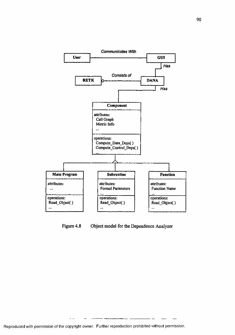
90
Communicates With
Has
Consists of
Has
DANA
User
RETK
GUI
operations: Read_Object()
attributes: Function Name
Function
attributes:Formal Parameters
operations: Read_Object()
Subroutine
operations: Read_Object()
attributes:
Main Program
operations: Compute_Data_Deps() Compute_Control_Deps()
attributes: Call Graph Metric Info
Component
Figure 4.8 Object model for the Dependence Analyzer
Reproduced with permission of the copyright owner. Further reproduction prohibited without permission.

object file associated with a component and return specific information from the se
quential design description. SL provides information on all variables, local variables,
non-local variables, variables declared as arrays, data-type information about a par
ticular variable, and state changes of a particular variable. An algorithm of the tasks
handled by SL is provided in Table 4.9.
43.2 Implementation
DANA was developed on an IBM RS/6000 machine running under the ADC
operating system. C++ was used to code DANA and compiled using a GNU Project
C++ compiler (Version 2.6). A diagram of the major processing steps is given in Fig
ure 4.9. The object files containing the individual design information of each
component served as the input to the programs. Since a component can be one of
three types, namely Main program, Subroutine, and Function, an appropriate method is
executed to read the design information about a component. Using the Call Graph the
dependence graph of each component is synthesized until the Main program is
reached. The synthesized dependence graph of the Main program constitutes the out
put of DANA— the program dependence graph (PDG).
The output format of DANA is both textual and graphical. The textual output
documents the use lists, definition lists of each site and the data dependences and con
trol dependences of the design. The graphical output is a file automatically generated
by DANA which is compatible with the UNIX program xfig. The xfig representation
uses boxes to represent sites. The dependences are represented as inter-site directed
edges. Different colors are used to represent the flow dependences (forward data
Reproduced with permission of the copyright owner. Further reproduction prohibited without permission.

92
Table 4.9 Algorithm for the slicer
// Algorithm for tasks handled by Slicer
Open Attribute File associated with a component Define List_of_All_VariabIes 1 Define List_of_Local_Variables 2 Define List_of_Non_LocaI_VariabIes 3 Define More lnformation 4
Read Request_Type
switch ( Request_Type) {
case 1: Read_Variab!e_Description_From_Attribute_File ( ) ; for All Variables {
return Varaible Description;}break;
case 2: Read_Variable_Description_From_Attribute_File ( ) ; for All Variables {
if (Variable.NonLocal = False) { return VariabIe_Description
}}break;
case 3: Read_Variable_Description_From_Attribute_File ( ) ; for All Variables {
if (Variable.NonLocal — True {return Variable_Description
}}break;
case 4: Read_Variable_Description_From_Attribute_File ( ); for All Variables {
return VariabIe_Description.Name return Variable_Description.Type return Variable_Description.Is_Array return Variable_Description.Dimensions return Variable_Description.NonLocal
}break;
Reproduced with permission of the copyright owner. Further reproduction prohibited without permission.

Figure 4.9
do for each Component
Read Object A tt r ib u te s '^ ^ )
Compute Data Dependences
Compute Control Dependences
Write To Text File
Generate x fig data files
end do
Combine Dependence Info
until <root> (Main) is reached
Major processing steps of the Dependence Analyzer
Reproduced with permission of the copyright owner. Further reproduction prohibited without permission.

94
flow), loop dependences (backward data flow), and control dependences so that the
design is clearly apparent to the user. Calls made to other subroutines and functions
from a given subroutine are represented as one single site, reflecting changes to formal
and common parameters. Table 4.10 shows the format of the textual dependence in
formation generated of a typical site.
An example of a code fragment for the scenario where a state change to array
variable NFACE occurs in a loop controlled by the loop variable I is listed in Table
4.11. The state changes for the code fragment shown in Table 4.11 are listed in Table
4.12. From Table 4.12 it can be observed that there are two state changes to variables.
The dependence analysis o f the state changes is listed in Table 4.13. The first two
sites correspond to the loop variable assignment and conditional testing for loop ter
mination. The third site corresponds to the state change to variable NFACE. The
definition lists and use lists of each site are also listed in Table 4.13. The first site
(row) of Table 4.13 corresponds to the assignment of the initial value to the loop vari
able I. The definition list variable for this site is I and the use list variables are y and e.
All constants are represented by the symbol y. The last use list variable of every site is
represented by the symbol e which stands for execution. If an edge exists between the
use list variable s of one site and the definition list variable of another site, then a con
trol dependence exists between the sites. The second site o f Table 4.13 corresponds to
the conditional testing of loop termination. The definition list variable for this site is x
which holds the results of the conditional test. The use list variables are the loop
scope index DO[0] and e. The third site of Table 4.13 corresponds to the assignment
statement to variable NFACE. The definition list variables of this site are NFACE and
Reproduced with permission of the copyright owner. Further reproduction prohibited without permission.

95
Table 4.10 Format o f the dependence information o f a typical site
Site-Number SiSite-Id : SidNumber of Use-List Variables: j Number of Def-List Variables: k Use-List Variables:
ULVjNumber of flow dependences: 1 fdi, fd2,..., fdiwhere fdx = <Sy, DLVj> n y < i n Sy.DLVz = ULV i
ULV2Number of flow dependences: 1 fdi, fd2,..., fdi
ULVj.,Number of flow dependences: 1 fd,,fd2,...,fd,
ULVj = eNumber of control dependences: m cdi, cd2,..., cdmwherecdx = <Sy,DLVz> n y < i n S y.DLVz = t x
Def-List Variables:DLV,
Number of loop dependences: n ldi, ld2,..., ldnwhere ldx = <Sy, ULVz> n y > i n Sy.ULVz = DLV,
DLV2Number of loop dependences: n ldi, ld2,...,ldn
DLVicNumber of loop dependences: n ldi, ld2,..., ldn
Reproduced with permission of the copyright owner. Further reproduction prohibited without permission.

96
Table 4.11 A code fragment to illustrate the analysis o f dependences
Line n: DO I = 1 ,6Line n+1: NFACE(I) = ILine n+2: END DO
Table 4.12 State changes of the code fragment listed in Table 4.11
Line State Change Variable Name
Rhs Variable(s) Type LoopScope
SemanticNature
n I 1,6 Iterative DO[0] LoopVariableAssignment
n+1 NFACE I Iterative DO[0] AssignmentStatement
Reproduced with permission of the copyright owner. Further reproduction prohibited without permission.

97
Table 4.13 Textual description of dependences of the____________________ state changes listed in Table 4.12________Site Number: 1 Site Id: n
Number of Use-List Variables: 2 Number of Def-List Variables: 1
Use-List Variables:Ys
Def-List Variables:__________________ I_____________________________________Site Number: 2 Site Id: n
Number of Use-List Variables: 2 Number of Def-List Variables: 1
Use-List Variables:DO[0]
Number of flow dependences : 1 Flow Dependences:< U >
sDef-List Variables:
______________________T____________________________________________Site Number: 3 Site Id: n+1
Number of Use-List Variables: 2 Number of Def-List Variables: 2
Use-List Variables:DO[0]
Number of flow dependences : 1 Flow Dependences:<1,I>
ENumber of control dependences: 1 Control Dependences:<2, T>
Def-List Variables:NFACEI
Number of loop dependences: 2 Loop Dependences:< 2, DO[0]>, < 3, I>
Reproduced with permission of the copyright owner. Further reproduction prohibited without permission.

98
I. The variable I needs to be included in the definition list of site 3 because site 3 cor
responds to the last state change within the loop scope. The use list variables of site 3
are I and s.
After all the sites are constructed, DANA computes the data and control de
pendences between the sites using the algorithms defined in Chapter 3. It can be
observed that there exists a flow data dependence between the definition list variable I
of site 1 and the use list variable DO[0] of site 2. Also, there is a flow data depend
ence between the definition list variable I of site 1 and the use list variable I of site 3.
There exists a control dependence between the definition list variable t of site 2 and
the use list variable e of site 3 indicating that site 3 is executed only of the loop is not
terminated. Loop data dependences exist from the definition list variable I of site 3 to
the use list variable DO[0] of site 2 and the use list variable I of site 3. Figure 4.10
shows an xfig graphical of the dependence analysis of the code fragment. Figure 4.10
depicts dependences in different shades of gray to simulate the different colors used in
the xfig representation. In addition to producing textual and graphical representations,
DANA generates dependence facts to be used by the Design Assistant (described in
Section 4.4). The dependence facts are generated for each component in the sequential
design.
4.4 Design Assistant
This section describes the design and implementation details of the design as
sistant. Before the design and implementation issues are discussed, a brief
Reproduced with permission of the copyright owner. Further reproduction prohibited without permission.

99
I
* »DO[0]
T
1'----3 -
I 8
EXP I
____________________________ Legend:
Control Dependence * Flow Data Dependence > Loop Data Dependence
Figure 4.10 An example xfig graphical representation of dependences
Reproduced with permission of the copyright owner. Further reproduction prohibited without permission.

100
introduction to NASA’s CLIPS [Clp 93a] [Clp 93b] [Clp 93c] is presented. Since
CLIPS is a comprehensive knowledge-based programming environment, only the in
formation relevant to this dissertation will be covered in the introduction to CLIPS.
4.4.1 CLIPS
The C-Language Interface Production System (CLIPS) is an expert system tool
developed at NASA’s Johnson Space Center. The first release of CLIPS was released
in 1985. Before CLIPS, LISP was used nearly in all expert system software tools at
NASA. However, LISP posed certain problems that impeded its use in expert systems
within NASA. The low availability of LISP on a broad range of conventional comput
ers, the high cost of LISP tools and hardware, and the poor integration of LISP with
other languages are some of the reasons why NASA chose to build CLIPS. The first
couple of versions of CLIPS were developed for internal use (within NASA). The first
release of CLIPS to the outside world was Version 3.0 in 1986. Since then CLIPS has
undergone many refinements and improvements. The most recent version of CLIPS is
Version 6.0 available both for UNIX-based systems and MS-DOS/MS-Windows based
systems. CLIPS has received widespread acceptance throughout the government, in
dustry, and academia. CLIPS can be integrated with external functions or applications.
A user can define external functions to CLIPS at any place a function can normally be
called. Once compiled and linked, all external functions can be used like built-in
functions within the CLIPS environment. In addition to being both portable and ex
tensible, CLIPS allows embedded applications to be built easily. It is possible to
embed CLIPS system calls in C, Ada, and FORTRAN programs.
Reproduced with permission of the copyright owner. Further reproduction prohibited without permission.

101
4.4.1.1 Knowledge Abstraction
Information in CLIPS can be represented using facts, objects, and global vari
ables. Facts indicate the truth or falsity of a certain piece of information. CLIPS
maintains a fact-list which consists of all the facts that are asserted. Facts in the fact-
list can be manipulated using the assert command to add facts, the retract command
to remove facts, the modify command to modify facts, and the duplicate command to
duplicate facts. Any number of facts may be added to the fact-list, which is limited
only by the memory capacity of the computer. CLIPS uses a fact-index to keep track
of the facts in the fact-list. Fact-index is an unique integer that is given to each new or
changed fact. Facts in CLIPS can either be ordered or non-ordered. Ordered facts
consists of a symbol followed by a sequence of zero or more fields. The entire fact is
enclosed in parenthesis1. The first field of an ordered fact specifies a “relation” that is
applied to the remaining fields. An example of a set of ordered fact is given below:
(FORTRAN-Program has Main-Program)(Main-Program name is “STATS")(FORTRAN-Program has 2 Subroutines)(FORTRAN-PROGRAM has I Functions)
Since ordered facts encode information positionally, a user must know the structure of
the data. On the other hand, non-ordered facts allows the user to assign names to each
field in the fact thereby providing an abstraction of the structure of the facts. A
deftemplate construct is used to create a template of a fact. Fields in the template are
1 In fact, all commands and constructs in CLIPS are delimited by an opening parenthesis on the left and a closing parenthesis on the right.
Reproduced with permission of the copyright owner. Further reproduction prohibited without permission.

102
called slots. Unlike fields in an ordered fact, default values can be specified for slots
in a non-ordered fact. An example of a non-ordered fact is given below:
(FORTRAN-Program (name “STATS")(number-of-subroutines 2)(mmber-of-functions 1))
The advantages of non-ordered facts are clarity and slot order independence. The def-
facts construct allows initial knowledge to be specified as a collection o f facts. When
the reset command is issued, all facts specified within a deffacts construct are added
the fact-list.
One of the unique features of CLIPS is that information can be represented
using objects. In CLIPS, an object is defined to be a symbol, a string, a floating-point
number or integer number, a multi-field value, an extemal-address, or an instance of a
user-defined class. The general notion of class and object of the object-oriented para
digm apply to classes and objects within CLIPS. A class is a template for common
attributes and methods of objects which are instances of that class. Objects in CLIPS
can be instances of primitive classes (such as SYMBOL and USER) and user-defined
classes. User-defined classes are defined using the defclass construct. Roles for each
class can be defined to be either abstract or concrete. Object instances of classes with
abstract roles cannot be created. Attributes of a class are specified using slots or mul
tislots. Methods or operations on attributes of a class are specified using defmessage-
handler construct. The difference between objects and non-ordered facts is that in
heritance allows the attributes and methods of a class to be described in terms of other
classes. CLIPS supports both single and multiple inheritance and is specified using is-
a link. An example of a user-defined class is shown below:
Reproduced with permission of the copyright owner. Further reproduction prohibited without permission.

103
(defclass Component (is-a USER) (role abstract)(slot num-components))
(dejmessage-handler Component increment-num-components 0 (+ ?self:nvm-components I))
Objects are created using the make-instance construct. CLIPS maintains an instance-
list of instances of all classes that are created. Just like facts, objects can also be ma
nipulated by adding using the make-instance construct and deleting using the
unmake-instance construct. The definstances construct allows initial knowledge to
be specified as a collection of objects. Whenever the reset command is issued, all ob
jects specified within a definstances construct are added the instance-list.
4.4.1.2 Knowledge Representation
Knowledge in CLIPS can be represented using the heuristic paradigm or the
procedural paradigm. A combination of both paradigms can also be used to represent
knowledge. Rules specify a set of “actions” to be performed whenever a set of condi
tions are satisfied. Rules are specified using the defrule construct. An example of a
rule is given below:
(defrule find-modularity(and (eq (find-instcmce ?ins Subroutine) FALSE)
(eq (find-instance ?ins Function) FALSE))= >
(printout t “No modules in program.Inter-Module parallelism not possible!” crlj))
CLIPS places rules as they defined in an agenda-list. CLIPS uses pattern matching to
determine which facts or objects satisfy the conditions specified by a particular rale. If
more than one rule is satisfied, a conflict resolution strategy is used by CLIPS to select
Reproduced with permission of the copyright owner. Further reproduction prohibited without permission.

104
a rule from the agenda-Iist CLIPS uses a forward-chaining inference procedure to
execute rules in the agenda-list. One concern with a forward-chaining procedure is
that there might be a search-explosion problem. This problem can be combated by
using the rules and procedural knowledge representation.
Procedural knowledge representation allows users to manipulate the knowl
edge in the CLIPS knowledge-base using deffunction construct. The deffunction
allow users to define procedural code in terms of CLIPS constructs. A combination of
procedural knowledge representation with rules controls the search process.
4.4.1.3 Inference Procedure
After a user builds the knowledge-base using facts, objects, rules, and func
tions, CLIPS is ready to execute. Rules are automatically executed by CLIPS whereas
user-defined functions (specified by deffunctions) have to be explicitly executed by the
user. However, if an user-defined function is specified as consequent of a rule, then
execution of such an user-defined function is controlled by the firing of the rule.
CLIPS provides seven conflict resolution strategies: depth, breadth, simplicity,
complexity, lex, mea, and random. The default strategy is depth which places newly
activated rules above all rules of the same salience. For example, given that an object
of class A activates rule-1 and rule-2 and an object of class B activates rule-3 and rule-
4, then if an instance of class A is asserted before an instance of class B, rule-3 and
rule-4 will be placed above rule-1 and rule-2 in the agenda-list. Positioning of rule-1
relative to rule-2 and rule-3 relative to rule-4 is arbitrary. For most cases the default
depth conflict resolution strategy works satisfactorily. A comprehensive discussion of
all the conflict resolution strategies can be found in [Clp 93a].
Reproduced with permission of the copyright owner. Further reproduction prohibited without permission.

105
4.4.2 Knowledge Representation of the Design Assistant
The information produced/analyzed by the Information Extractor and Depend
ence Analyzer forms the base for program facts and dependence facts, respectively.
Since human intervention is inevitable in any knowledge-based application, user in
formation forms the base for user facts. All facts are encoded using CLIPS constructs
and CLIPS object-oriented language (COOL). Rules on how to react to different facts
are encoded into the knowledge repository. In addition to rules, procedural knowledge
is encoded into the knowledge repository using deffunction constructs. Figure 4.11
shows the overall design of the design assistant.
Table 4.14 shows the knowledge representation of program facts. The top
most class is Component which is a sub-class of USER which is a primitive class in
CLIPS. All user-defined classes in CLIPS must be sub-classes of USER. Main-
Program, Subroutine, Function are some of the sub-classes of Component. The roles
of all classes except that of Component are defined to be concrete, thus allowing in
stances to be created. Other classes include Subroutine-Calls, Function-Calls, DO-
Loop-Information, IF-Conditions, Variable-Description, State-Changes, Labeled-
Commons, and Un-Labeled Commons. All classes are sub-classes of Component.
The attributes of each class are specified using slots and mutislots. The nomenclature
for each attribute of a given class should be clearly inferred in the context of the class
definition. For example, the class Subroutine has three attributes: 1) Name, which cor
responds to the name of the subroutine, 2) Sub-Formals, which corresponds to the list
of formal parameters of the subroutine, and 3) Num-formals, which corresponds to the
number of formal parameters.
Reproduced with permission of the copyright owner. Further reproduction prohibited without permission.

106
Program Dependence UserFacts Facts Facts
Knowledge Repository
CLIPS Knowledge-Based Programming Environment JParallel Design Recommendations
Figure 4.11 Overall design of the Design Assistant
Reproduced with permission of the copyright owner. Further reproduction prohibited without permission.

107
Table 4.14 Representation o f program facts in CLIPS
(defclass Component (is-a USER)(role abstract)(slot comp-name (create-accessor read-write)) (slot num-calls (create-accessor read-write)) (slot num-funcs (create-accessor read-write)) (slot num-locals (create-accessor read-write))
Definition o f class component Role Abstract
; Name o f the component Number o f subroutine calls Number o f Function calls Number o f variables for component Number o f state changes(slot num-states (create-accessor read-write))
(slot num-labeled-commons (create-accessor read-write)) ; Number o f labeled Commons (slot num-un-Iabeled-commons (create-accessor read-write)); Number o f unlabeled Comms (slot num-do-loops (create-accessor read-write)) ; Number o f DO Loops(slot num-if-conds (create-accessor read-write))) ; Number o f IF Conditions
(defclass Main-Program (is-a Component)(role concrete)(slot Name (create-accessor read-write)))
(defclass Subroutine (is-a Component)(role concrete)(slot Name (create-accessor read-write))(multislot Sub-Formals (create-accessor read-write)) (slot num-formals (create-accessor read-write)))
(defclass Function (is-a Component)(role concrete)(slot Name (create-accessor read-write))(multislot Fun-Formals (create-accessor read-write)) (slot num-formals (create-accessor read-write)))
(defclass Subroutine-Calls (is-a Component)(role concrete)(slot sub-name (create-accessor read-write))(slot sub-line (create-accessor read-write))(slot sub-call-seq-no (create-accessor read-write)) (multislot sub-actuals (create-accessor read-write)) (slot act-count (create-accessor read-write)))
(defclass Function-Calls (is-a Component)(role concrete)(slot fun-name (create-accessor read-write))(slot fun-line (create-accessor read-write))(slot fun-call-seq-no (create-accessor read-write)) (multislot fun-actuals (create-accessor read-write)) (slot act-count (create-accessor read-write)))
(defclass DO-Loop-Information (is-a Component) (role concrete)(slot DO-Start-Line (create-accessor read-write)) (slot DO-Last-Line (create-accessor read-write))(slot DO-Label (create-accessor read-write))
(table con’d.)
Reproduced with permission of the copyright owner. Further reproduction prohibited without permission.

108
(slot DO-Counting-Variable (create-accessor read-write)) (slot DO-Inidal-Value (create-accessor read-write))(slot DO-Limit (create-accessor read-write))(slot DO-Step (create-accessor read-write))(slot DO-Nesting-Level (create-accessor read-write))(slot DO-Prev-Type (create-accessor read-write))(slot DO-Prev-Id (create-accessor read-write)))
(defclass IF-Conditions (is-a Component)(role concrete)(slot IF-Start-Line (create-accessor read-write))(slot IF-True-Part-Last-Line (create-accessor read-write)) (slot IF-False-Part-Last-Line (create-accessor read-write)) (slot IF-Logical_Expression (create-accessor read-write)) (slot IF-Nesting-Level (create-accessor read-write))(slot IF-Prev-Type (create-accessor read-write))(slot IF-Prev-Id (create-accessor read-write)))
(defclass Variable-Description (is-a Component)(role concrete)(slot Var-Name (create-accessor read-write))(slot Type (create-accessor read-write))(slot Declared (create-accessor read-write))(slot Array (create-accessor read-write))(multislot Dimensions (create-accessor read-write))(slot Non-Local (create-accessor read-write)))
(defclass State-Changes (is-a Component)(role concrete)(slot Line-Num (create-accessor read-write))(slot Var-Name (create-accessor read-write))(multislot Rhs-Variables (create-accessor read-write)) (slot Category (create-accessor read-write)))
(defclass Labeled-Commons (is-a Component)(role concrete)(slot Common-Name (create-accessor read-write)) (multislot Commons (create-accessor read-write))(slot Commons-Count (create-accessor read-write)))
(defclass Un-Labeled-Commons (is-a Component)(role concrete)(multislot Commons (create-accessor read-write))(slot Commons-Count (create-accessor read-write)))
Reproduced with permission of the copyright owner. Further reproduction prohibited without permission.

109
The class definitions shown in Table 4.14 serve as templates for object in
stances. All the slots include a create-accessor facet which instructs CLIPS to
automatically create explicit message-handlers for reading and writing data to a slot.
Explicit message-handlers are created for each slot for each class. The general format
of the message-handier that is created by CLIPS for the create-accessor facet of a slot
with read access privilege is shown below:
(definessage-handler <class> get-<slot-name> primary 0 ?self:<slot-name>)
The general format of the message-handier that is created by CLIPS for the create-
accessor facet of a slot with write access privilege is shown below:
(definessage-handler <class> put-<slot-name> primary 0 (?value)(bind ?self:<slot-name> ?value))
The design of each component in the original sequential design description will be
encoded as program facts in CLIPS by creating object-instances of the classes.
Table 4.15 shows the knowledge representation of dependence facts. The top
most class is Component which is a sub-class of USER and is defined in Table 4.14.
Six new classes are defined for representing dependence information: 1) Site is a sub
class of Component and corresponds to site information, 2) Use-Lists is a sub-class of
Site and corresponds to the use list of a site, 3) Def-Lists is a sub-class of Site and cor
responds to the definition list of a site, 4) Du-Edges is a sub-class of Use-Lists and
corresponds to flow dependences between variables, 5) Ud-Edges is a sub-class of
Def-Lists and corresponds to loop dependences between variables, and 6) Cd-Edges is
a sub-class of Use-Lists and corresponds to control dependences between sites. CLIPS
Reproduced with permission of the copyright owner. Further reproduction prohibited without permission.

110
Table 4.15 Representation o f dependence facts in CLIPS
(defclass Site (is-a Component)(role concrete)(slot Site-Id (create-accessor read-write))(slot Site-Number (create-accessor read-write))(slot Number-of-UIs (create-accessor read-write))(slot Number-of-Dls (create-accessor read-write))(slot Number-of-Cds (create-accessor read-write)))
(defclass Use-Lists (is-a Site)(role concrete)(slot Use-List-Name (create-accessor read-write))(slot Number-of-Dus (create-accessor read-write)))
(defclass Def-Lists (is-a Site)(role concrete)(slot Def-List-Name (create-accessor read-write))(slot Number-of-Uds (create-accessor read-write)))
(defclass Du-Edges (is-a Use-Lists)(role concrete)(slot Du-Edges-Name (create-accessor read-write))(slot Du-Dest-Site-Number (create-accessor read-write)))
(defclass Ud-Edges (is-a Def-Lists)(role concrete)(slot Ud-Edges-Name (create-accessor read-write))(slot Ud-Dest-Site-Number (create-accessor read-write)))
(defclass Cd-Edges (is-a Use-Lists)(role concrete)(slot Cd-Edges-Name (create-accessor read-write))(slot Cd-Dest-Site-Number (create-accessor read-write)))
Reproduced with permission of the copyright owner. Further reproduction prohibited without permission.

I l l
creates explicit message-handlers for each slot in the class definition via the specifica
tion of the create-accessor facet. Dependence information of each component, which
includes the Program Dependence Graph, is encoded as dependence facts by creating
object-instances o f the classes.
4.4J Inference Mechanism of the Design Assistant
The inference mechanism for ascertaining the parallelization potential in the
original program involves the specification of rules (for heuristic knowledge) and
functions (for procedural knowledge) into the knowledge repository to react to the
program and dependence facts. We define a set of scenarios which help assess the
parallelization potential and then formulate the defined set of scenarios into the
knowledge repository.
We have identified a set of six scenarios by which parallelization po
tential is identified. Of the six scenarios, five cover intra-component parallelism and
one covers inter-component parallelism. Description of the scenarios and the formal
definitions are given below. If there is potential for intra-component parallelism, then
the parallel design recommendations are coarse-grained. If there is potential for inter
component parallelism, then the parallel design recommendations are fine-grained.
Scenario 1 (Intra-Component Parallelism):
Consider two simple calls to subroutines Sub-1 and Sub-2 from Component-X (by
definition a simple call to a subroutine is one which is not invoked in a loop). If Sub-1
and Sub-2 have different actual parameters and Sub-1 and Sub-2 do not modify La
beled or Un-labeled Common Variables, then the calls to Sub-1 and Sub-2 can be
parallelized. The formal definition of Scenario 1 is:
Reproduced with permission of the copyright owner. Further reproduction prohibited without permission.

112
Let Call-1 and Call-2 be two subroutine calls from Component-X.Let Sub-1 and Sub-2 be the called subroutines in Call-1 and Call-2 respectively.Let api(l), ap2(I), . . . , apr(1) be the actual parameters of subroutine Sub-1 in call Call-1. Let api(2), ap2(2), . . . , aps(2) be the actual parameters of subroutine Sub-2 in call Call-2. Let cvj(I), cv2(l), . . . , cvt(,) be the common variables of subroutine Sub-1.Let cv / 2), c v 2(2), . . . , cvu(2) be the common variables of subroutine Sub-2.Let st-cvx(y) be a boolean variable which indicates whether or not a state change occurs to common variable cvx in subroutine Sub-y. for all ( i = 1, r and j = 1, s)
if( apj(I)* ap/2)) thenfor all ( k = 1, t and 1 = 1, u)
if( st-cvk(1) = False and st-cvi(2) = False )then parallel (Call-1, Call-2) = True
end ifend for
end ifend for
Scenario 2 (Intra-Component Parallelism):
Consider two simple calls to subroutines Sub-1 and Sub-2 from Component-X. If
Sub-1 and Sub-2 have common actual parameters, and Sub-1 and Sub-2 do not modify
Labeled or Un-labeled Common Variables, and the common actual parameters them
selves are not modified then the calls to Sub-1 and Sub-2 can be parallelized. The
formal definition of this scenario is:
Let Call-1 and Call-2 be two subroutine calls from Component-X.Let Sub-1 and Sub-2 be the called subroutines in Call-1 and Call-2 respectively.Let api(1), ap2(I), . . . , apr(I) be the actual parameters of subroutine Sub-1 in call Call-1. Let api(2), ap2(2), . . . , aps(2) be the actual parameters of subroutine Sub-2 in call Call-2. Let cvi(1), cv2(1), . . . , cvt(,) be the common variables of subroutine Sub-1.Let cv i(2), cv 2{2), . . . , cv m be the common variables of subroutine Sub-2.Let st-cvx^ be a boolean variable which indicates whether or not a state change occurs to common variable cvx in subroutine Sub-y.Let st-apw(z) be a boolean variable which indicates whether or not a state change occurs to formal parameter aliased to the actual parameter apw in subroutine Sub-z.
Reproduced with permission of the copyright owner. Further reproduction prohibited without permission.

113
for all ( i = 1, r and j = 1, s)if ( exists m and n such that 1 < m < r, 1 < n < s and apm(l) = ap„(2)) then
if ( st-apm(I) = False and st-ap„(2) = False )then for all ( k = 1, t and 1 = 1, u)
if( st-cvk(1) = False and st-cvi(2) = False )then parallel (Call-1, Call-2) = True
end ifend for
end ifend if
end for
Scenario 3 (Intra-Component Parallelism):
Consider two simple calls to subroutines Sub-1 and Sub-2 from Component-X. If
Sub-1 and Sub-2 have different actual parameters, and Sub-1 and Sub-2 access
(read/write) Labeled and/or Un-labeled Common Variables at different locations, then
the calls to Sub-1 and Sub-2 can be parallelized. The formal definition of Scenario 3
is:
Let Call-1 and Call-2 be two subroutine calls from Component-X.Let Sub-1 and Sub-2 be the called subroutines in Call-1 and Call-2 respectively.Let apt(l), ap2(l), . . . , apr(1) be the actual parameters o f subroutine Sub-1 in call Call-1. Let api(2), ap2 (2), . . . , aps(2) be the actual parameters o f subroutine Sub-2 in call Call-2. Let cvi(1), cv2(1), . . . , cvt(I) be the common variables o f subroutine Sub-1.Let cv i(2), cv 2{1\ . . . , cvu(2> be the common variables of subroutine Sub-2.Let st-cvx^ be a boolean variable which indicates whether or not a state change occurs to common variable cvx in subroutine Sub-y. for all ( i = 1, r and j = 1, s)
if ( api(1) * ap/2 )) thenfor aU ( k = 1, t and 1 = 1, u)
if ( exists g and h such that l < g < t , l < h < u and st- cvg l) = True and st- cvh(2) = True ) then
if (cvg(1) * cvh(2)) thenparallel (Call-1, Call-2) = True
end ifend if
end forend if
end for
Reproduced with permission of the copyright owner. Further reproduction prohibited without permission.

114
Scenario 4 (Intra-Component Parallelism):
Consider two simple calls to subroutines Sub-1 and Sub-2 from Component-X. If
Sub-1 and Sub-2 have common actual parameters, and Sub-1 and Sub-2 access
(read/write) Labeled and/or Un-labeled Common Variables at different locations, and
the common actual parameters themselves are not modified, then the calls to Sub-1
and Sub-2 may be parallelized. Scenario 4 is formally defined as:
Let Call-1 and Call-2 be two subroutine calls from Component-X.Let Sub-1 and Sub-2 be the called subroutines in Call-1 and Call-2 respectively.Let api(1), ap2(1), . . . , apr(l) be the actual parameters of subroutine Sub-1 in call Call-1. Let api(2), ap2(2), . . . , aps(2) be the actual parameters of subroutine Sub-2 in call Call-2. Let cvt(1), cv2(1), . . . , cvt(1) be the common variables of subroutine Sub-1.Let cv i(2), cv 2(2), . . . , cv u(2) be the common variables of subroutine Sub-2.Let st-cvx^ be a boolean variable which indicates whether or not a state change occurs to common variable cv* in subroutine Sub-y.Let st-apw(z) be a boolean variable which indicates whether or not a state change occurs to formal parameter aliased to the actual parameter apw in subroutine Sub-z. for all ( i = 1, r and j = 1, s)
if ( exists m and n such that 1< m < r, 1 < n < s and apm(1) = apn(2)) then if ( st-apm(1) = False and st-apn(2) = False )then
for all ( k = 1, t and I = 1, u)if ( exists g and h such that l < g < t , l < h < u and
st- cvg^ = True and st- cvh(2) = True ) then if (cvg(I)* cvh(2)) then
parallel (Call-1, Call-2) = Trueend if
end ifend for
end ifend if
end for
Scenario 5 (Intra-Component Parallelism):
Consider a call to subroutine Sub from Component-X within a loop. Let Sub(l) be the
call in the i th iteration of the loop and Sub(l+1) be the call in the i+1 th iteration of the
loop. If the actual parameters of Sub(,) and Sub(,+1) are different and Common vari-
Reproduced with permission of the copyright owner. Further reproduction prohibited without permission.

115
ables are not modified, all the iterations of the loop may be parallelized. The formal
definition of Scenario 5 is:
Let Call111 and Call11*11 be two calls to the same subroutine Sub from Component-X within a loop in iteration I and iteration 1+1 respectively.Let Subm and SubfI+I1 be the calls to subroutine Sub iteration I and iteration I+l respectively.Let apira, ap2W, . . . , aprm be the actual parameters of subroutine Sub in iteration I.Let api*I+,l, ap2P+I1, • . •, aps +I1 be the actual parameters of subroutine Sub in iteration I+l.Let cv.W cv2m, . . . , cvtm be the common variables of subroutine Sub in iteration I.Let c v r ’J, cv2P+l], . . . , cvut[+I' be the common variables of subroutine Sub in iteration I+l.Let st-cvx be a boolean variable which indicates whether or not a state change occurs to common variable cvx in subroutine Sub-y.Let st-apw be a boolean variable which indicates whether or not a state change occurs to formal parameter aliased to the actual parameter apw in subroutine Sub-z. for all ( i = 1, r and j = 1, s)
if ( apjm * ap/I+11) thenfor all ( k = 1, t and 1 = 1, u)
if ( st-cvkm = False and st-cvp11 = False )then parallel (Calf^, CalPH]) in loop = True
end ifend for
end ifend for
Scenario-6 (Inter-Component Parallelism):
This scenario applies only to loops within a given component. Let {Sti, St2, . . . , Stm}
be a set of state changes within a loop. Let {Stj(1), St2(1), . . . , Stm(1)}, {St/2), St2(2), . . . ,
Stm(2)} ,. . . , {St,(n), St2(n), . . . , St,n(n)} be the set of state changes with the loop unrolled.
If for all j = 1, 2, . . ., m, and k = 1, 2 ,. . ., n, St/k) are independent, then set of com
putations described by {Sti, St2 , . . ., Stm} may be partitioned into parallel
computations. Scenario 6 is formally defined as:
Reproduced with permission of the copyright owner. Further reproduction prohibited without permission.

116
Let Sti, St2 , . . Stm be a set of state changes within a loop in Component-X.Let S t,^ St2[11, . . Stm111 be the state changes in iteration 1.Let St,™, St2™ , . . Stm™ be the state changes in iteration N.Let Sitei, Site2 , . . Sitem be the list of sites for the corresponding state changes. Let Sites-ulvi, Sites-ulv2 , . . . , Sites-uivp be the use list variables of site s.Let Sites- dlv i, Sites- dlv2 , . . . , Sites- dlvq be the definition list variables of site s. for all ( j = 1, ma n dk = 1, N)
for all (1 = 1, p and r = 1, q)if ( not exists t and u 1 < t, u < m such that
Sitet-dlvr = Siteu-ulv,) thenpartition (Sti, St2 , . . . , Stm) = True
end ifend for
end for
Table 4.16 shows the encoding of the general purpose functions (rules) and the
encoding of the scenarios using CLIPS deffunction construct. Explanation of the
functions is provided in Table 4.16 using CLIPS commenting style. All characters
after a semicolon are ignored by CLIPS.
4.5 Execution
The program facts, dependence facts, and the knowledge repository are loaded into the
CLIPS environment using the load command. Each component has two knowledge
base files: 1) program fact file, and 2) dependence fact file. Once all the facts are in
place, a reset command is issued. The reset command creates object instances of ap
propriate classes for each component. Subsequently, the run command is issued and
the parallel design recommendations are output to the user. Chapter 5 presents ex
perimental results from RETK and the parallelization methodology.
Reproduced with permission of the copyright owner. Further reproduction prohibited without permission.

117
Table 4.16 Representation o f the knowledge repository
(deffimction extcalls (?parent) ; This function extracts the subroutine calls of a(do-for-all-instances ((?a Calls)) ; component identified by the variable ?parent
TRUE(if (eq (send ?a get-comp-name) ?parent) then(printout t ?a:sub-name crlf)))(return)else(printout t "No Subroutine Calls!" crlf))
(deffimction extfims (?parent) ; This function extracts the function calls of a(do-for-all-instances ((?a Func-Calls)) ; component identified by the variable ?parent
TRUE(if (eq (send ?a get-comp-name) ?parent) then(printout t ?a:fun-name crlf)))(return)else(printout t "No Function Calls!" crlf))
(deffimction get-number-of-calls (?ins-name ?ins-type); Return number o f subroutine calls (if (class-existp ?ins-type) ; o f a class instance ?ins-namethen ; and class type ?ins-type(do-for-all-instances ((?x ?ins-type))
TRUE(if (and (or (eq ?ins-type Main-Program) (eq ?ins-type Subroutine)
(eq ?ins-type Function))(eq ?x:Name ?ins-name))
then(return ?x:num-calls)))FALSE(if (or (eq ?ins-type Main-Program) (eq ?ins-type Subroutine)
(eq ? ins-type Function))then(printout t ? in s -n a m e N o such instance o f type " ?ins-type crlf)
(return))FALSE(printout t "Query type not allowed for Class " ?ins-type crlf)(return))FALSE(if (not (class-existp ?ins-type)) then(printout t ? in s - ty p e N o such class" crlf)))
(table con’d.)
Reproduced with permission of the copyright owner. Further reproduction prohibited without permission.

118
(deffimction get-number-of-funcs (?ins-name ?ins-type); Return number of subroutine calls (if (class-existp ?ins-type) ; o f a class instance ?ins-namethen ; and class type ?ins-type(do-for-all-instances ((?x ?ins-type))
TRUE(if (and (or (eq ?ins-type Main-Program) (eq ?ins-type Subroutine)
(eq ?ins-type Function))(eq ?x:Name ?ins-name))
then(return ?x:num-funcs)))FALSE(if (or (eq ?ins-type Main-Program) (eq ?ins-type Subroutine)
(eq ? ins-type Function))then(printout t ?ins-name No such instance o f type" ?ins-type crlf)
(return))FALSE
(printout t "Query type not allowed for Class " ?ins-type crlf)(return))
FALSE(if (not (class-existp ?ins-type)) then(printout t ?ins-type No such class" crlf)))
(deffimction get-number-of-locals (?ins-name ?ins-type); Return number of local variables(if (class-existp ?ins-type)then(do-for-all-instances ((?x ?ins-type))
TRUE(if (and (or (eq ?ins-type Main-Program) (eq ?ins-type Subroutine)
(eq ?ins-type Function))(eq ?x:Name ?ins-name))
then(return ?x:num-locals)))FALSE(if (or (eq ?ins-type Main-Program) (eq ?ins-type Subroutine)
(eq ?ins-type Function))then(printout t ? in s-n am eN o such instance o f type" ?ins-type crlf)
(return))FALSE
(printout t "Query type not allowed for Class " ?ins-type crlf)(return))
FALSE(if (not (class-existp ?ins-type)) then(printout t ?ins-type No such class" crlf)))
(table con’d.)
Reproduced with permission of the copyright owner. Further reproduction prohibited without permission.

119
(deffimction get-number-of-states (?ins-name ?ins-type); Return number o f states(if (class-existp ?ins-type)then(do-for-all-instances ((?x ?ins-type))
TRUE(if (and (or (eq ?ins-type Main-Program) (eq ?ins-type Subroutine) (eq ?ins-type
Function))(eq ?x:Name ?ins-name))
then(return ?x:num-states)))FALSE(if (or (eq ?ins-type Main-Program) (eq ?ins-type Subroutine)
(eq ?ins-type Function))then(printout t ?ins-name No such instance o f ty p e" ?ins-type crlf)
(return))FALSE
(printout t "Query type not allowed for Class " ?ins-type crlf)(return))
FALSE(if (not (class-existp ?ins-type)) then(printout t ? in s - ty p e N o such class" crlf)))
(deffimction get-number-of-labeled-commons (?ins-name ?ins-type)(if (class-existp ?ins-type) ; Return number o f labeled commonsthen(do-for-all-instances ((?x ?ins-type))
TRUE(if (and (or (eq ?ins-type Main-Program) (eq ?ins-type Subroutine)
(eq ?ins-type Function))(eq ?x:Name ?ins-name))
then(return ?x:num-labeled-commons)))FALSE(if (or (eq ?ins-type Main-Program) (eq ?ins-type Subroutine)
(eq ?ins-type Function))then(printout t ?ins-name No such instance o f type " ?ins-type crlf)
(return))FALSE
(printout t "Query type not allowed for Class " ?ins-type crlf)(return))
FALSE(if (not (class-existp ?ins-type)) then(printout t ?ins-type": No such class" crlf)))
(table con’d.)
Reproduced with permission of the copyright owner. Further reproduction prohibited without permission.

120
(deffimction get-number-of-un-labeled-commons (?ins-name ? ins-type)( if (class-existp ?ins-type) ; Return number o f un-labeled commonsthen(do-for-all-instances ((?x ?ins-type))
TRUE(if (and (or (eq ? ins-type Main-Program) (eq ?ins-type Subroutine) (eq ?ins-type
Function))(eq ?x:Name ?ins-name))
then(return ?x:num-un-labeled-commons)))FALSE(if (or (eq ?ins-type Main-Program) (eq ?ins-type Subroutine)
(eq ?ins-type Function))then(printout t ?ins-name No such instance o f type" ?ins-type crlf)
(return))FALSE
(printout t "Query type not allowed for Class " ?ins-type crlf)(return))
FALSE(if (not (class-existp ? ins-type)) then(printout t ?ins-type No such class" crlf)))
(deffimction get-number-of-do-loops (?ins-name ?ins-type)(if (class-existp ?ins-type) ; Return number o f do loopsthen(do-for-all-instances ((?x ?ins-type))
TRUE(if (and (or (eq ?ins-type Main-Program) (eq ?ins-type Subroutine)
(eq ?ins-type Function))(eq ?x:Name ?ins-name))
then(return ?x:num-do-Ioops)))FALSE(if (or (eq ?ins-type Main-Program) (eq ?ins-type Subroutine)
(eq ?ins-type Function))then(printout t ?ins-name No such instance o f type" ?ins-type crlf)
(return))FALSE
(printout t "Query type not allowed for Class " ?ins-type crlf)(return))
FALSE(if (not (class-existp ?ins-type)) then(printout t ?ins-type No such class" crlf)))
(table con’d.)
Reproduced with permission of the copyright owner. Further reproduction prohibited without permission.

121
(deffimction get-number-of-if-conditions (?ins-name ?ins-type)(if (class-existp ?ins-type) ; Return number o f if conditionsthen(do-for-all-instances ((?x ? ins-type))
TRUE(if (and (or (eq ?ins-type Main-Program) (eq ?ins-type Subroutine)
(eq ?ins-type Function))(eq ?x:Name ?ins-name))
then(return ?x:num-if-conds)))FALSE(if (or (eq ?ins-type Main-Program) (eq ?ins-type Subroutine)
(eq ? ins-type Function))then(printout t ?ins-name No such instance o f ty p e" ?ins-type crlf)
(return))FALSE
(printout t "Query type not allowed for Class ” ?ins-type crlf)(return))
FALSE(if (not (class-existp ?ins-type)) then(printout t ?ins-type No such class" crlf)))
(deffimction scenario-1-1 (?comp)(do-for-instance ((?fl Func-Calls) (?f2 Func-Calls))
(and (eq ?fl :fim-name ?f2:fun-name)(eq ?fl:corap-name ?£2:comp-name)(eq ?fl:comp-name ?comp)(neq ?fl:fim-actuals ?f2:fim-actuals)(find-instance ((?Fl Function))
(and (eq ?Fl:Name ?fl:fun-name)(eq ?Fl:num-labeled-commons nil)(eq ?Fl:num-un-labeIed-commons nil)))
(find-instance ((?F2 Function))(and (eq ?F2:Name ?E:fun-name)
(eq ?F2:num-Iabeled-commons nil)(eq ?F2:num-un-Iabeled-commons nil))))
(printout t "Scenario 1.1" crlf ••------------- crlf crlf"Function C all" ?fl:fim-name " o f "?fl:comp-name " at line number" ?fl:fun-Iine crlf " <— Can be Parallelized with - > " crlf "Function Call" ?f2:fun-name " o f "?f2:comp-name " at line number " ?f2:fun-line crlf crlf))
(table con’d.)
Reproduced with permission of the copyright owner. Further reproduction prohibited without permission.

122
(return)FALSE(printout t "Calls cannot be parallelized " ?comp crlf))
(deffimction scenario-1-2 (?comp)(do-for-instance ((?sl Calls) (?s2 Calls))
(and (eq ?s 1 :sub-name ?s2:sub-name)(eq ?sl:comp-name ?s2:comp-name)(eq ?sl:comp-name ?comp)(neq ?sl:sub-actuals ?s2:sub-actuals)(find-instance ((?S1 Subroutine))
(and (eq ?S 1 :Name ?s 1 :sub-name)(eq ?Sl:num-Iabeled-commons nil)(eq ?S 1 :num-un-Iabeled-cotnmons nil)))
(find-instance ((?S2 Subroutine))(and (eq ?S2:Name ?s2:sub-name)
(eq ?S2:num-labeIed-commons nil)(eq ?S2:num-un-labeled-commons nil))))
(printout t "Scenario 1.2" crlf ••-------------» crlf crlf"Subroutine C all" ?sl:sub-nam e" of "?sl:comp-name " at line number ” ?sl:sub-Iine crlf ” <— Can be Parallelized with —> " crlf "Subroutine Call " ?s2:sub-name " o f "?s2:comp-name " at line number " ?s2:sub-line crlf crlf))
(return)FALSE(printout t "Calls cannot be parallelized " ?comp crlf))
(deffimction scenario-1-3 (?comp)(do-for-instance ((?sl Calls) (?f2 Func-Calls))
(and (eq ?s 1 :sub-name ?f2:fun-name)(eq ?sl :comp-name ?f2:comp-name)(eq ?sl :comp-name ?comp)(neq ?s 1 :sub-actuals ?f2:fun-actuals)(find-instance ((?S1 Subroutine))
(and (eq ?S 1 :Name ?s 1 :sub-name)(eq ?Sl:num-Iabeled-commons nil)(eq ?Sl:num-un-Iabeled-commons nil)))
(find-instance ((?F2 Function))(and (eq ?F2:Name ?C:fim-name)
(eq ?F2:num-labeled-commons nil)(eq ?F2:num-un-labeled-commons nil))))
(table con’d.)
Reproduced with permission of the copyright owner. Further reproduction prohibited without permission.

123
(printout t "Scenario 1.3 ” crlf ••------------•• c rlf crlf"Subroutine Call " ?sl:sub-name" o f "?slxomp-name " at line number " ?sl:sub-line crlf " < - Can be Parallelized with - > " crlf "Function Call " ?G:fun-name " o f "?f2:comp-name " at line number " ?f2:fun-line crlf crlf))
(return)FALSE(printout t "Calls cannot be parallelized " ?comp crlf))
(deffimction scenario-2-1 (?comp)(do-for-instance ((?fl Func-Calls) (?£2 Func-Calls))
(and (eq ?fl :fun-name ?£2:fun-name)(eq ?fl:comp-name ?£2:comp-name)(eq ?fl xomp-name ?comp)(eq ?fl:fim-actuals ?f2:fun-actuals)(find-instance ((?sl State-Changes))
(eq ?s 1 :comp-name ?fl :fim-name)) (find-instance ((?s2 State-Changes))
(eq ?s2xomp-name ?£2:fim-name))(or (and (eq ?sl :Var-Name ?fl :fun-actuals)
(neq ?s2:Var-Name ?f2:fim-actulas)) (and (neq ?s 1: Var-Name ?fl rfiin-actuals)
(eq ?s2:Var-Name ?f2:fim-actuals))) (find-instance ((?F1 Function))
(and (eq?Fl:Name?fl:fim-name)(eq ?Fl:num-IabeIed-commons nil)(eq ?Fl:num-un-labeIed-commons nil)))
(find-instance ((?F2 Function))(and (eq ?F2:Name ?f2:fim-name)
(eq ?F2:num-labeIed-commons nil)(eq ?F2:num-un-Iabeled-commons nil))))
(printout t "Scenario 2.1 " crlf "------------ " crlf crlf"Function C all" ?fl :fun-name " o f "?flxomp-name " at line number " ?fl :fim-line crlf " <— Can be Parallelized with - > " crlf "Function Call" ?G:fun-name" of "?Qxomp-name " at line number " ?Q:fim-Iine crlf crlf))
(return)FALSE(printout t "Calls cannot be parallelized " ?comp crlf))
(table con’d.)
Reproduced with permission of the copyright owner. Further reproduction prohibited without permission.

124
(deffimction scenario-2-2 (?comp)(do-for-instance ((?si Calls) (?s2 Calls))
(and (eq ?s 1 .sub-name ?s2:sub-name)(eq ?sl xomp-name ?s2xomp-name)(eq ?sl xomp-name ?comp)(eq ?sl:sub-actuals ?s2:sub-actuals)(find-instance ((?tl State-Changes))
(eq ?tl xomp-name ?sl:sub-name))(find-instance ((?t2 State-Changes))
(eq ?t2xomp-name ?s2:sub-name))(or (and (eq ?tl: Var-Name ?sl :sub-actuals)
(neq ?t2:Var-Name ?s2:sub-actulas)) (and (neq ? tl: Var-Name ?s I :sub-actuals)
(eq ?t2: Var-Name ?s2:sub-actuals))) (find-instance ((?S1 Subroutine))
(and (eq ?S 1 :Name ?s 1 :fun-name)(eq ?Sl:num-!abeled-commons nil)(eq ?Sl:num-un-Iabeled-commons nil)))
(find-instance ((?S2 Subroutine))(and (eq ?S2:Name ?s2:fim-name)
(eq ?S2:num-labeled-commons nil)(eq ?S2:num-un-labeled-commons nil))))
(printout t "Scenario 2 2 " crlf"-------------» crif crif"Subroutine Call " ?si:sub-name " o f "?sl xomp-name " at line number " ?sl:sub-line crlf " <— Can be Parallelized with - > " crlf "Subroutine Call " ?s2:sub-name" o f "?s2xomp-name " at line number " ?s2:sub-Iine crlf crlf))
(return)FALSE(printout t "Calls cannot be parallelized " ?comp crlf))
(deffimction scenario-2-3 (?comp)(do-for-instance ((?sl Calls) (?f2 Func-Calls))
(and (eq ?sl:sub-name ?f2:fun-name)(eq ?sl xomp-name ?f2:comp-name)(eq ?sl xomp-name ?comp)(eq ?sl:sub-actuals ?£2:fun-actuals)(find-instance ((?tl State-Changes))
(eq ?tl xomp-name ?sl:sub-name))(find-instance ((?t2 State-Changes))
(eq ?t2xomp-name ?£2:fun-name))(or (and (eq ?tl: Var-Name ?sl:sub-actuals)
(neq ?t2:Var-Name ?f2:fun-actulas))(and (neq ?tl: Var-Name ?sl:sub-actuals)
(eq ?t2: Var-Name ?f2:fun-actuals)))
(table con’d.)
Reproduced with permission of the copyright owner. Further reproduction prohibited without permission.

125
(find-instance ((?S1 Subroutine))(and (eq ?S 1 :Name ?s 1 :sub-name)(eq ?Sl:num-labeled-commons nil)(eq ?S 1 :num-un-labeled-commons nil)))
(find-instance ((?F2 Function))(and (eq ?F2:Name ?12:fun-name)(eq ?F2:num-Iabeled-commons nil)(eq ?F2:num-un-Iabeled-commons nil))))
(printout t "Scenario 2.3 " crlf "------------ " crlf crlf"Subroutine Call " ?sl:sub-name " o f "?sl xomp-name " at line number " ?sl:sub-line crlf " <— Can be Parallelized with —> " crlf "Function C all" ?f2:fun-name " o f "?f2:comp-name " at line number " ?f2:fun-line crlf crlf))
(return)FALSE(printout t "Calls cannot be parallelized " ?comp crlf))
(deffimction scenario-3-1 (?comp)(do-for-instance ((?fl Func-Calls) (?f2 Func-Calls))
(and (eq ?fl :fun-name ?f2:fun-name)(eq ?fl xomp-name ?f2xomp-name)(eq ?fl xomp-name ?comp)(neq ?fl :fim-actuals ?£2:fiin-actua!s)(find-instance ((?F1 Function))
(and (eq ?F 1 :Name ?fl :fun-name)(or (neq ?Fl:num-labeled-commons nil)
(neq ?Fl:num-un-IabeIed-commons nil)))) (find-instance ((?F2 Function))
(and (eq ?F2:Name ?£2:fun-name)(or (eq ?F2:num-Iabeled-commons nil)
(eq ?F2:num-un-labeled-commons nil)))) (find-instance ((?LComl Labeled-Commons))
(eq ?LComl.comp-name ?fl:fiin-name)) (find-instance ((?LCom2 Labeled-Commons))
(eq ?LCom2xomp-name ?f2:fiin-name)) (find-instance ((?tl State-Changes))
(eq ?tl xomp-name ?fl:fun-name)) (find-instance ((?t2 State-Changes))
(eq ?t2xomp-name ?f2:fun-name))(or (and (eq ?tl :Var-Name ?LCom 1 :Commons) (neq ?t2:Var-Name ?LCom2:Commons))(and (neq ?tl:Var-Name ?LComl:Commons) (eq ?t2:Var-Name ?LComl:Commons))))
(table con’d.)
Reproduced with permission of the copyright owner. Further reproduction prohibited without permission.

126
(printout t "Scenario 3 .1" crlf ------------- •• crlf crlf"Function C all" ?fl:fim-name " o f "?fl:comp-name " at line number " ?fl:fun-line crlf " <— Can be Parallelized with —> " crlf "Function Call" ?f2:fun-name " o f "?f2:comp-name " at line number " ?f2:fun-line crlf crlf))
(return)FALSE(printout t "Calls cannot be parallelized " ?comp crlf))
(deffimction scenario-3-2 (?comp)(do-for-instance ((?sl Calls) (?s2 Calls))
(and (eq ?s 1 :sub-name ?s2:sub-name)(eq ?sl xomp-name ?s2:comp-name)(eq ?sl xomp-name ?comp)(neq ?sl:sub-actuals ?s2:sub-actuals)(find-instance ((?S1 Subroutine))
(and (eq ?S1 :Name ?sl :sub-name)(or (neq ?S 1 :num-labeled-commons nil)(neq ?Sl:num-un-IabeIed-commons nil))))
(find-instance ((?S2 Subroutine))(and (eq ?S2:Name ?s2:sub-name)(or (eq ?S2:num-IabeIed-commons nil)(eq ?S2:num-un-labeled-commons nil))))
(find-instance ((?LComl Labeled-Commons))(eq ?LComl xomp-name ?s 1 :sub-name))
(find-instance ((?LCom2 Labeled-Commons))(eq ?LCom2xomp-name ?s2:sub-name))
(find-instance ((?tl State-Changes))(eq ?tl xomp-name ?sl :sub-name))
(find-instance ((?t2 State-Changes))(eq ?t2xomp-name ?s2:sub-name))(or (and (eq ?tl :Var-Name ?LComl :Commons) (neq ?t2:Var-Name ?LCom2:Commons))(and (neq ?tl:Var-Name ?LComl:Commons) (eq ?t2:Var-Name ?LComl :Coramons))))
(printout t "Scenario 3 2 " crlf -<------------ » crlf crlf"Subroutine Call " ?sl:sub-name" o f "?sl xomp-name " at line number " ?sl :sub-line crlf “ <— Can be Parallelized with —> " crlf "Subroutine Call " ?s2:sub-name " o f "?s2xomp-name " at line number " ?s2:sub-Iine crlf crlf))
(return)FALSE(printout t "Calls cannot be parallelized " ?comp crlf))
(table con’d.)
Reproduced with permission of the copyright owner. Further reproduction prohibited without permission.

127
(deffimction scenario-3-3 (?comp)(do-for-instance ((?sl Calls) (?f2 Func-Calls))
(and (eq ?sl :sub-name ?f2:fun-name)(eq ?sl xomp-name ?f2:comp-name)(eq ?sl xomp-name ?comp)(neq ?s I -.sub-actuals ?f2:fim-actuals)(find-instance ((?S1 Subroutine))
(and (eq?Sl:Name?sl:sub-name)(or (neq ?Sl:num-IabeIed-commons nil)
(neq ?Sl:num-un-Iabeled-commons nil)))) (find-instance ((?F2 Function))
(and (eq ?F2:Name ?12:fun-name)(or (eq ?F2:num-labeled-commons nil)
(eq ?F2:num-un-Iabeled-commons nil)))) (find-instance ((?LComl Labeled-Commons))
(eq ?LComl xomp-name ?sl :sub-name)) (find-instance ((?LCom2 Labeled-Commons))
(eq ?LCom2xomp-name ?f2:fun-name)) (find-instance ((?tl State-Changes))
(eq ?tl xomp-name ?sl:sub-name)) (find-instance ((?t2 State-Changes))
(eq ?t2xomp-name ?f2:fun-name))(or (and (eq ?tl:Var-Name ?LComl -.Commons) (neq ?t2:Var-Name ?LCom2:Commons))(and (neq ? t l : Var-Name ?LComl :Commons) (eq ?t2: Var-Name ?LComl:Commons))))
(printout t "Scenario 3.3 " crlf ••------------ •• crlf crlf"Subroutine C all" ?sl:sub-name " o f "?sl xomp-name " at line number " ?sl :sub-line crlf " <— Can be Parallelized with - > " crlf "Function Call " ?£2:fiin-name " o f "?Cxomp-name " at line number " ?f2:fun-line crlf crlf))
(return)FALSE(printout t "Calls cannot be parallelized " ?comp crlf))
(deffimction scenario-4-1 (?comp)(do-for-instance ((?fl Func-Calls) (?f2 Func-Calls))
(and (eq ?fl :fun-name ?f2:fim-name)(eq ?fl xomp-name ?£2xomp-name)(eq ?fl xomp-name ?comp)(eq ?fl:fun-actuals ?£2:fun-actuals)
(find-instance ((?F1 Function))(and (eq ?F1 :Name ?fl :fun-name)(or (neq ?F1 :num-labeled-commons nil)
(neq ?F1 :num-un-Iabeled-commons nil))))
(table con’d.)
Reproduced with permission of the copyright owner. Further reproduction prohibited without permission.

128
(find-instance ((?F2 Function))(and (eq ?F2:Name ?G:fun-name)
(or (eq ?F2:num-labeIed-commons nil)(eq ?F2:num-un-Iabeled-commons nil))))
(find-instance ((?LComl Labeled-Conunons))(eq ?LComl xomp-name ?fl:fun-name))
(find-instance ((?LCom2 Labeled-Commons))(eq ?LCom2xomp-name ?f2:fun-name))
(find-instance ((?tl State-Changes))(eq ?tl xomp-name ?fl:fun-name))
(find-instance ((?t2 State-Changes))(eq ?t2xomp-name ?£2:fun-name))(or (and (eq ? t l : Var-Name ?LCom 1 :Commons)(neq ?t2:Var-Name ?LCom2:Commons))(and (neq ?tl:Var-Name ?LComl:Commons)
(eq ?t2: Var-Name ?LComl:Commons))) (find-instance ((?t3 State-Changes))
(eq ?t3 xomp-name ?fl:fun-name))(find-instance ((?t4 State-Changes))
(eq ?t4xomp-name ?£2:fun-name))(or (and (eq ?t3: Var-Name ?fl :fim-actuals)
(neq ?t4:Var-Name ?f2:fim-actulas))(and (neq ?t3: Var-Name ?fl:fim-actuals)(eq ?t4:Var-Name ?f2:fun-actuals))))
(printout t "Scenario 4.1 " crlf «------------- " crlf crlf"Function C all" ?fl:fim-name" o f "?fl xomp-name " at line number " ?fl :fun-line crlf " <— Can be Parallelized with - > ” crlf "Function Call" ?f2:fim-name " o f "?f2xomp-name " at line number " ?f2:fun-line crlf crlf))
(return)FALSE(printout t "Calls cannot be parallelized " ?comp crlf))
(deffimction scenario-4-2 (?comp)(do-for-instance ((?sl Calls) (?s2 Calls))
(and (eq ?s 1 :sub-name ?s2:sub-name)(eq ?sl xomp-name ?s2xomp-name)(eq ?sl xomp-name ?comp)(eq ?sl:sub-actuals ?s2:sub-actuals)(find-instance ((?S1 Subroutine))
(and (eq ?S 1 :Name ?s 1 :sub-name)(or (neq ?S1 :num-labeled-commons nil)
(neq ?S 1 :num-un-labeled-commons nil)))) (find-instance ((?S2 Subroutine))
(and (eq ?S2:Name ?s2:sub-name)(or (eq ?S2:num-labeled-commons nil)
(eq ?S2:num-un-Iabeled-commons nil))))
(table con’d.)
Reproduced with permission of the copyright owner. Further reproduction prohibited without permission.

129
(find-instance ((?LComl Labeled-Commons))(eq ?LComl xomp-name ?sl:sub-name))
(find-instance ((?LCom2 Labeled-Commons))(eq ?LCom2xomp-name ?s2:sub-name))
(find-instance ((?tl State-Changes))(eq ?tl xomp-name ?sl:sub-name))
(find-instance ((?t2 State-Changes))(eq ?t2xomp-name ?s2:sub-name))(or (and (eq ?tl:Var-Name ?LComl:Commons) (neq ?t2:Var-Name ?LCom2:Commons))(and (neq ?tl:Var-Name ?LComl’.Commons) (eq ?t2:Var-Name ?LComl:Commons)))
(find-instance ((?t3 State-Changes))(eq ?t3 xomp-name ?sl:sub-name))
(find-instance ((?t4 State-Changes))(eq ?t4xomp-name ?s2:sub-name))(or (and (eq ?t3: Var-Name ?s 1 :sub-actuals)
(neq ?t4:Var-Name ?s2:sub-actulas)) (and (neq ?t3: Var-Name ?sl:sub-actuals)
(eq ?t4:Var-Name ?s2:sub-actuals)))) (printout t "Scenario 4.2 " crlf
"------------ " crlf crlf"Subroutine Call ” ?sl:sub-name" o f "?sl xomp-name " at line number " ?sl:sub-line crlf " < - Can be Parallelized with - > " crlf "Subroutine C a ll" ?s2:sub-name " o f "?s2xomp-name " at line number ” ?s2:sub-line crlf crlf))
(return)FALSE(printout t "Calls cannot be parallelized " ?comp crlf))
(deffimction scenario-4-3 (?comp)(do-for-instance ((?sl Calls) (?f2 Func-Calls))
(and (eq ?s 1 :sub-name ?f2:fim-name)(eq ?sl xomp-name ?f2 xomp-name)(eq ?sl xomp-name ?comp)(eq ?sl:sub-actuals ?f2:fun-actuals)(find-instance ((?S1 Subroutine))
(and (eq ?S 1 :Name ?s 1 :sub-name)(or (neq ?S 1 :num-labeIed-commons nil)
(neq ?Sl:num-un-Iabeled-commons nil)))) (find-instance ((?F2 Function))
(and (eq ?F2:Name ?f2:fun-name)(or (eq ?F2 :num-labeled-commons nil)
(eq ?F2:num-un-IabeIed-commons nil)))) (find-instance ((?LComl Labeled-Commons))
(eq ?LComl xomp-name ?sl :sub-name)) (find-instance ((?LCom2 Labeled-Commons))
(eq ?LCom2xomp-name ?f2:fim-name))
(table con’d.)
Reproduced with permission of the copyright owner. Further reproduction prohibited without permission.

130
(find-instance ((?tl State-Changes))(eq ?tl xomp-name ?sl :sub-name))
(find-instance ((?t2 State-Changes))(eq 7t2xomp-name ?f2:fun-name))(or (and (eq ?tl:Var-Name ?LComl:Commons)
(neq ?t2:Var-Name ?LCom2:Commons)) (and (neq ?t I: Var-Name ?LComl:Commons)
(eq ?t2: Var-Name ?LComl:Commons))) (find-instance ((?t3 State-Changes))
(eq ?t3 xomp-name ?sl:sub-name))(find-instance ((?t4 State-Changes))
(eq ?t4xomp-name ?f2:fun-name))(or (and (eq ?t3 :Var-Name ?sl:sub-actuals)(neq ?t4:Var-Name ?C2:fun-actuIas))
(and (neq ?t3: Var-Name ?sl:sub-actuals)(eq ?t4:Var-Name ?f2:fim-actuals))))
(printout t "Scenario 4.3 " crlf "------------ » crlf crlf"Subroutine C all" ?sl:sub-nam e" o f "?s I xomp-name " at line number " ?sl .sub-line crlf " <— Can be Parallelized with —> " crlf "Function C all" ?f2:fun-name" o f "?f2xomp-name
” at line number" ?f2:fun-line crlf crlf))(return)FALSE(printout t "Calls cannot be parallelized " ?comp crlf))
(deffimction scenario-5 (?comp)(do-for-instance ((?sl Calls))
(and (eq ?s 1 xomp-name ?comp)(find-instance ((?I1 DO-Loop-Information))
(eq ?I1 xomp-name ?sl xomp-name))(> ?sl:sub-line ?Il:DO-Start-Line)(<= ?s 1 :sub-line ?I1 :DO-Last-Line)(neq ?sl:sub-actuals ?s2:sub-actuals)(find-instance ((?S1 Subroutine))
(and (eq ?S 1 :Name ?s 1 :sub-name)(eq ?Sl:num-labeled-commons nil)(eq ?Sl:num-un-IabeIed-commons nil)))
(printout t "Scenario 5 " crlf"------------- " crlf crlf"Subroutine Call " ?sl:sub-name " o f "?sl xomp-name " at line number" ?sl:sub-line crlf " <~ Can be Parallelized within the loop —> " crlf " Identified b y " ?I1 .'Label " at Relative L ine" crlf " Line Number" ?I1 :DO-Start-Line crlf crlf))
(table con’d.)
Reproduced with permission of the copyright owner. Further reproduction prohibited without permission.

131
(return)FALSE(printout t "Calls cannot be parallelized " ?comp crlf))
(deffimction scenario-6 (?comp)(do-for-instances ((?sl State-Changes))
(and (eq ?s 1 xomp-name ?comp)(find-instance ((?I1 DO-Loop-Information))
(eq ?I1 xomp-name ?sl xomp-name))(> ?sl:sub-line ?I1:D0-Start-Line)(<= ?sl:sub-line ?I1:D0-Last-Line)(not (find-instance ((?E1 Site))
(eq ?E1 xomp-name ?sl xomp-name)) (find-instance ((?DLV Def-Lists))
(eq ?DLVxomp-name ?E1 xomp-name)) (find-instance ((?ULV Use-Lists))
(eq ?ULVxomp-name ?E1 xomp-name))(eq ?DLV:Def-List-Name ?ULV:Use-List-Name)))
(printout t "Scenario 6 ” crlf••------------- •• crlf crlf"State Changes " ?sl:Var-name" o f "?sl xomp-name " at line number " ?sl:Line-Num crlf " <— Can be Parallelized within the loop —> " crlf " Identified by " ?I1 :Label" at Relative Line " crlf " Line Number " ?I1:D0-Start-Line crlf crlf))
(return)FALSE(printout t "State Changes cannot be parallelized " ?comp crlf))
Reproduced with permission of the copyright owner. Further reproduction prohibited without permission.

Chapter 5
Experimental Results
In this chapter, we present experimental results of applying the methodology to
test programs by the reverse engineering toolkit (RETK). To demonstrate the full ca
pabilities of the methodology and of RETK, comprehensive results for a simple
sample program are described. Summary results for larger programs are then pro
vided.
5.1 A Sample Program
A sample program which reads two sets of data values for a statistics experi
ment and computes the standard deviation of the each set of experimental values is
shown in Table 5.1. The analysis of the sample program by RETK involves the ex
traction of the sequential design description by the Information Extractor (IE),
dependence analysis by the Dependence Analyzer (DANA), and derivation of parallel
design recommendations by the CLIPS-based Design Assistant (DA). The output of
each component is given.
5.1.1 Information Extraction
The output of the Information Extractor is the sequential design of the original
program. Snapshots of the session with IE are shown in Figures 5.1 - 5.3. Metric in
formation for an original assessment of the program is shown in Figure 5.1. Figure 5.1
132
Reproduced with permission of the copyright owner. Further reproduction prohibited without permission.

133
Table 5.1 A sample FORTRAN program
ccc
MAIN PROGRAM TO CALCULATE THE STANDARD DEVIATIONPROGRAM STATISTICS INTEGER M, N
c EXPA - OBSERVATIONS FROM EXPERIMENT Ac EXPB - OBSERVATIONS FROM EXPERIMENT B
REAL EXPA(14), EXPB(14), STDA, STDB CALL INPUT(M, EXPA, N, EXPB)
c STDA - STANDARD DEVIATION OF OBSERVATIONS OF EXPERIMENT STDA = STD(EXPA, M)
Ac STDB - STANDARD DEVIATION OF OBSERVATIONS OF EXPERIMENT
STDB = STD(EXPB, N)CALL PRINT(EXPA, M, STDA, EXPB, N, STDB)END
B
c *** SUBROUTINE INPUT *** SUBROUTINE INPUT(M, EXPA,N,EXPB) INTEGER M, N REAL EXPA(14), EXPB(14)READ(5,*) M DO 10 1=1,14
READ(5,15) EXPA(I)15 FORMAT (F4.1)10 CONTINUE
READ(5,*) N DO 20 J=l, 14
READ(5,30) EXPB(J)30 FORMAT (F4.1)20 CONTINUE
ENDC *** FUNCTION STD ***
FUNCTION STD(EXPX,X)INTEGER XREAL MEAN, EXPX(14), IND(14), TOT TOT = 0 SUM = 0 DO 60 I = 1,X
TOT = TOT + EXPX(I)60 CONTINUE
MEAN = TOT / X DO 70 J = 1,X
IND(J) = MEAN - EXPX (J) SUM = SUM + IND(J)**2
70 CONTINUESTD = SQRT(SUM/(X—1)) END
C * * * SUBROUTINE PRINT * * *SUBROUTINE PRINT(EXPA,M,STDA, EXPB,N,STDB)REAL STDA, STDB, EXPA(14), EXPB(14)WRITE(6,80) 'EXPERIMENT A -------- ' , 'MEASUREMENTS',
* ( (EXPA(I)),1=1,M)80 FORMAT (T2,A20/T5,A14/(T10,F4.1))
WRITE(6,90) 'STANDARD DEVIATION', STDA90 FORMAT CO'//T5, A22, F5 .2)
WRITE(6,100) 'EXPERIMENT B ---------' , 'MEASUREMENTS',( (EXPB(J)) ,J=1,N)
100 FORMAT ('O'////T2,A20/T5,A14/(T10,F4.1)) WRITE(6,90) 'STANDARD DEVIATION', STDB RETURN END
Reproduced with permission of the copyright owner. Further reproduction prohibited without permission.

Figure 5.1 Metric Information o f the sample program
Reproduced with permission of the copyright owner. Further reproduction prohibited without permission.

reveals that there are 4 components in the program: the MAIN program (called
STATS), 2 subroutines, INPUT and PRINT, and 1 user-defined function STD. The
call graph of the program is shown in Figure 5.2. Figure 5.2 shows that the MAIN pro
gram calls subroutine INPUT once, function STD twice, and subroutine PRINT once.
Neither INPUT nor PRINT calls any other component. Function STD does not call
any other component but makes use of the FORTRAN built-in square-root function
SQRT*. The asterisks at the end of SQRT* is an indication to the user that it is a
built-in function. Each component of the original program is represented as an
X/Motif-based button in the call graph representation. An user may click any of the
components to obtain complete information about the component. The information
includes the name of the component, metric information, subroutine call information,
function call information, formal parameters, if any, of the component, variable de
scription and state change information. Figure 5.3 shows an X/Motif-based scrollable
text window for click event of the MAIN program component. A complete descrip
tion of the design of the MAIN program is given in Tables 5.2-5.7.
Metric information like total number of lines in the module, number o f commented
lines, number of blank lines, number of discriminations in the module, and McCabe’s
cyclomatic complexity are listed in Table 5.2. LOC (lines of code), another widely
accepted metric, can be calculated directly from the information listed in Table 5.2 by
subtracting the sum of commented and blank lines from the total number of lines in
the module. Tables 5.3 and 5.4 list the details of subroutines and functions called from
MAIN. The type column in Tables 5.3 and 5.4 describes the manner in which a par
ticular subroutine or function is called.
Reproduced with permission of the copyright owner. Further reproduction prohibited without permission.

Figure 5.2 Call graph o f the sample program
Reproduced with permission of the copyright owner. Further reproduction prohibited without permission.
Figure 5.3 Information about MAIN program of sample program
Reproduced with permission of the copyright owner. Further reproduction prohibited without permission.

138
Table 5.2 Metric Information o f MAIN
Total Number of Lines
TotalNumber o fCommentedLines
Total Number of Blank Lines
TotalNumber of Discriminations
McCabe's Cyciomatic Complexity
15 7 0 0 I
Table 5.3 Summary of subroutine calls of MAIN
Name o f the subroutine in the CALL
Actual parameters in the CALL
Calling Sequence Number
Type of CALL
INPUT M 1 SimpleEXPANEXPB
PRINT EXPA 2 SimpleMSTDAEXPBNSTDB
Table 5.4 Summary of function calls of MAIN
Name o f the Actual parameters Calling Sequence Typesubroutine in the CALL in the CALL Number of CALLSTD EXPA 1 Simple
MSTD EXPB 2 Simple
N
Reproduced with permission of the copyright owner. Further reproduction prohibited without permission.

139
Local and non-local variable descriptions are listed in Table 5.5. The type col
umn of Table 5.5 details the type of variable. For those variables that are explicitly
declared, the Information Extractor associates the explicit type declaration to a vari
able. However, for those variables that are not explicitly declared, the Information
Extractor infers the type using the FORTRAN implicit variable naming convention.
The state change information for MAIN is shown in Table 5.6. The column loop
scope is relevant only when the state change for a particular variable under considera
tion occurs within a loop. The type column of Table 5.6 describes the type of state
change. Additional information about MAIN is listed in Table 5.7. Typical additional
information about a Main Program component includes labeled and unlabeled COM
MON variable description.
The design information for the rest of the components of the original program
is listed in Tables 5.8 - 5.25. Information about subroutine INPUT is listed in Tables
5.8-5.13. Information about subroutine PRINT is listed in Tables 5.14-5.19. Infor
mation about function STD is listed in Tables 5.20 - 5.25. The word “<None>”
appears in the first column of a table for which information is absent. For example,
subroutines INPUT and PRINT do not call any other subroutines or functions. There
fore, the word “<None>” appears in the first column of Tables 5.9, 5.10, 5.15, and
5.16. For all subroutines and user-defined functions, tables which list additional in
formation about a particular component include a formal variable description in
addition to a COMMON variable description.
Reproduced with permission of the copyright owner. Further reproduction prohibited without permission.

140
Table 5.5 Summary o f variable description o f MAIN
VariableName
Type IsDeclared
IsArray
Dimensions Scope
M INT yes no LocalN INT yes no LocalEXPA REAL yes yes 14 LocalEXPB REAL yes yes 14 LocalSTDA REAL yes no LocalSTDB REAL yes no LocalSTD REAL no no Function Return
Table 5.6 Summary of state changes of MAIN
Line State Change Variable Name
Rhs Variable(s) Type LoopScope
SemanticNature
11 STDA STD, EXPA, M Simple Assignmentstatement
13 STDB STD, EXPB, N Simple Assignmentstatement
Table 5.7 Additional information about MAIN
NO Labeled Common Variables.
NO Unlabeled Common Variables.
Reproduced with permission of the copyright owner. Further reproduction prohibited without permission.

141
Table 5.8 Metric information o f subroutine INPUT
Total Number o f Lines
TotalNumber ofCommentedLines
Total Number o f Blank Lines
TotalNumber o f Discriminations
McCabe's Cyclomatic Complexity
15 1 0 2 3
Table 5.9 Summary of subroutine calls of subroutine INPUT
Name o f the subroutine in the CALL
Actual parameters in the CALL
Calling Sequence Number
Type o f CALL
<None>
Table 5.10 Summary of function calls of subroutine INPUT
Name o f the subroutine in the CALL
Actual parameters in the CALL
Calling Sequence Number
Type o f CALL
<None>
Table 5.11 Summary of variable description of subroutine INPUT
VariableName
Type IsDeclared
IsArray
Dimensions Scope
M INT yes no FormalN INT yes no FormalEXPA REAL yes yes 14 FormalEXPB REAL yes yes 14 FormalI INT no no LocalJ INT yes no Local
Reproduced with permission of the copyright owner. Further reproduction prohibited without permission.

142
Table 5.12 Summary o f state changes o f subroutine INPUT
Line State Change Variable Name
Rhs Variable(s) Type LoopScope
SemanticNature
5 M Simple READstatement
6 I 1, 14 Iterative DO[0] Loop Variable Assignment
7 EXPA I Iterative DO[0] READStatement
10 N Simple READstatement
11 J 1, 14 Iterative DO[l] Loop Variable Assignment
12 EXPB J Iterative DO[l] READStatement
Table 5.13 Additional information of subroutine INPUT
Formal Parameters: M, EXPA, N, EXPB
NO Labeled Common Variables.
NO Unlabeled Common Variables.
Table 5.14 Metric information of subroutine PRINT
Total Number o f Lines
TotalNumber ofCommentedLines
Total Number o f Blank Lines
TotalNumber o f Discriminations
McCabe's Cyclomatic Complexity
12 1 0 0 1
Reproduced with permission of the copyright owner. Further reproduction prohibited without permission.

143
Table 5.15 Summary o f subroutine calls o f subroutine PRINT
Name o f the subroutine in the CALL
Actual parameters in the CALL
Calling Sequence Number
Type o f CALL
<None>
Table 5.16 Summary of function calls of subroutine PRINT
Name o f the subroutine in the CALL
Actual parameters in the CALL
Calling Sequence Number
Type of CALL
<None>
Table 5.17 Summary of variable description of subroutine PRINT
VariableName
Type IsDeclared
IsArray
Dimensions Scope
M INT yes no FormalN INT yes no FormalEXPA REAL yes yes 14 FormalEXPB REAL yes yes 14 FormalI INT no no LocalJ INT yes no Local
Table 5.18 Summary of state changes of subroutine PRINT
Line State Change Variable Name
Rhs Variable(s) Type LoopScope
SemanticNature
<None>
Reproduced with permission of the copyright owner. Further reproduction prohibited without permission.

144
Table 5.19 Additional information o f subroutine PRINT
Formal Parameters: EXPA, M, STDA, EXPB, N, STDA
NO Labeled Common Variables.
NO Unlabeled Common Variables.
Table 5.20 Metric information of function STD
Total Number o f Lines
TotalNumber ofCommentedLines
Total Number o f Blank Lines
TotalNumber o f Discriminations
McCabe's Cyclomatic Complexity
16 1 0 2 3
Table 5.21 Summary of subroutine calls of function STD
Name o f the Actual parameters Calling Sequence Typesubroutine in the CALL in the CALL Number o f CALL<None>
Table 5.22 Summary of function calls of function STD
Name o f the Actual parameters Calling Sequence Typesubroutine in the CALL in the CALL Number o f CALLSQRT* SUM/(X-1) 1 Simple
Reproduced with permission of the copyright owner. Further reproduction prohibited without permission.

145
Table 5.23 Summary o f variable description o f function STD
VariableName
Type IsDeclared
IsArray
Dimensions Scope
X INT yes no FormalMEAN REAL yes no LocalEXPX REAL yes yes 14 FormalIND REAL yes yes 14 LocalTOT REAL no no LocalSUM REAL no no LocalI INT no LocalJ INT no LocalSTD REAL Implicit Function Return
Table 5.24 Summary of state changes of function STD
Line State Change Variable Name
Rhs Variable(s) Type LoopScope
SemanticNature
5 TOT 0 Simple AssignmentStatement
6 SUM 0 Simple AssignmentStatement
7 I i,x Iterative DO[0] Loop Variable Assignment
8 TOT TOT, EXPX, I Iterative DO[0] AssignmentStatement
10 MEAN TOT, X Simple AssignmentStatement
11 J i,x Iterative DO[l] Loop Variable Assignment
12 IND J, MEAN, EXPX Iterative DO[l] AssignmentStatement
13 SUM SUM, IND, J, 2 Iterative DO[l] AssignmentStatement
15 STD SUM, X, 1 Simple AssignmentStatement
Table 5.25 Additional information of function STD
Formal Parameters: EXPX, X
NO Labeled Common Variables.
NO Unlabeled Common Variables.
Reproduced with permission of the copyright owner. Further reproduction prohibited without permission.

146
5.1.2 Dependence Analysis
The sequential design representations produced by the Information Extractor
were presented in Section 5.1.2. Using these design representations, the Dependence
Analyzer computes the data and control dependences of each component. Subse
quently, the program dependence graph (PDG) of each component is constructed. As
mentioned in Chapter 4, the dependences are represented both textually and graphi
cally. The dependences are computed for each component in the design and later
synthesized to form the PDG. The call graph is used as the basis for the construction
of the PDG that proceeds in a bottom-up manner.
The textual description of the dependences of subroutine INPUT is listed in
Table 5.26. The format described in Table 4.10 of Chapter 4 is used to represent in
formation regarding dependences. The first row of Table 5.26 indicates the total
number of sites for subroutine INPUT. Subsequent rows of Table 5.26 list the par
ticulars of each site: site number, site id, number of use list variables, number of
definition list variables, use list variables, number of flow dependences (if any), flow
dependences (if any), number of control dependences ( if any), control dependences (if
any), definition list variables, number of loop dependences (if any), and loop depend
ences (if any). It has to be noted that the first site (Site 0) consists of only definition
list variables and the last site (Site 9 in this case) consists of only use list variables.
The symbols “y”, “x”, and “e” in the notation described in [Jack 94] are represented as
“*Gamma*”, “*Tau*’\ and “*E*” respectively. The asterisks are used to differentiate
these special variables from possible use as variable names in a program.
Reproduced with permission of the copyright owner. Further reproduction prohibited without permission.

147
Table 5.26 Textual description o f dependences o f subroutine INPUT
Total Number o f Sites: 10
Site Number 0 Site Id: 1
Number o f Use-List Variables: 0 Number o f Def-List Variables: 4
Def-List Variables:MNEXPA
_______________________ EXPB________________________Site Number: 1 Site Id: 5
Number o f Use-List Variables: 2 Number o f Def-List Variables: 1
Use-List Variables:♦File**E*
Def-List Variables:______________________M__________________________Site Number 2 Site Id: 6
Number of Use-List Variables: 2 Number o f Def-List Variables: 1
Use-List Variables:♦Gamma**E*
Def-List Variables:_______________________I_____________________________Site Number: 3 Site Id: 6
Number o f Use-List Variables: 2 Number o f Def-List Variables: 1
Use-List Variables:DO[0]
Number o f flow dependences: 1 Flow Dependences:
<2, I>*E*
Def-List Variables:♦Tau*
(table con’d.)
Reproduced with permission of the copyright owner. Further reproduction prohibited without permission.

148
Site Number 4 Site Id: 7
Number o f Use-List Variables: 2 Number o f Def-List Variables: 2
Use-List Variables:I
Number o f flow dependences: 1 Flow Dependences:
<2, I>*E*
Number o f control dependences: 1 Control Dependences:<3, *Tau‘>
Def-List Variables:EXPAI
Number o f loop dependences: 2 Loop Dependences:<4, I>, <3, I>
Site Number 5 Site Id: 10
Number o f Use-List Variables: 2 Number o f Def-List Variables: 1
Use-List Variables: ‘ File**E*
Def-List Variables:N
Site Number: 6 Site Id: 11
Number o f Use-List Variables: 2 Number o f Def-List Variables: 1
Use-List Variables: ‘ Gamma**E*
Def-List Variables:J
Site Number: 7 Site Id: 11
Number o f Use-List Variables: 2 Number o f Def-List Variables: 1
Use-List Variables:DO[l]
Number of flow dependences: 1 Flow Dependences:
<6, J>*E*
Def-List Variables:*Tau*
(table con’d.)
Reproduced with permission of the copyright owner. Further reproduction prohibited without permission.

149
Site Number 8 Site Id: 12
Number o f Use-List Variables: 2 Number o f Def-List Variables: 2
Use-List Variables:J
Number o f flow dependences: 1 Flow Dependences:
<6, J>*E*
Number o f control dependences: 1 Control Dependences:<7, *Tau*>
Def-List Variables:EXPBJ
Number of loop dependences: 2 Loop Dependences:<8, J>, <7, J>
Site Number: 9 Site Id: 12
Number o f Use-List Variables: 6 Number o f Def-List Variables: 0
Use-List Variables:M
Number o f flow dependences: 1 Flow Dependences:
<1, M>N
Number o f flow dependences: I Flow Dependences:
<5, N>EXPA
Number o f flow dependences: 1 Flow Dependences:
<4, EXPA>EXPB
Number o f flow dependences: 1 Flow Dependences:
<8, EXPB>I
Number o f flow dependences: 1 Flow Dependences:
<4, I>J
Number o f flow dependences: 1 Flow Dependences:
<8, J>
Reproduced with permission of the copyright owner. Further reproduction prohibited without permission.

150
In addition to the textual description of dependences described in Table 5.26, a
xfig based graphical representation of the dependences is automatically generated by
the Dependence Analyzer for each component. The xfig depiction of the dependence
graph of subroutine INPUT is shown in Figure 5.4. In order to show all the sites in the
dependence graph, the original picture was zoomed in at the ratio of 10:1 . A blowup
of sites 3 and 4 is shown in Figure 5.5. The dependences are represented as edges
between the sites. The actual xfig representation uses different color encoding for easy
identification of the dependences. Some of the color encoding is apparent in Figure
5.5. In particular, edges which represent loop dependences are shown thick when
compared to flow or control dependences edges which are shown thin.
The textual description of dependences of subroutine PRINT and the user-
defined function STD are listed in Tables 5.27 and 5.28 respectively. As defined in
Chapter 4, an abstract site is built for all subroutines and user-defined functions. A
component’s abstract site’s use list variable(s) are the non-local variables of the mod
ule which include formal parameters and COMMON variables. The definition list
variables of the abstract site are the same non-local variables to which a state change
occurs within the module. The textual description of the abstract site of subroutine
INPUT is given in Table 5.29. The abstract site description of subroutine PRINT and
user-defined function STD are listed in Tables 5.30 and 5.31 respectively.
The textual description of the dependences of the MAIN program is shown in
Table 5.32. Sites which represent calls to subroutines and user defined-functions from
MAIN are replaced by the abstract sites.
Reproduced with permission of the copyright owner. Further reproduction prohibited without permission.

151
Figure 5.4 Dependence graph of subroutine INPUT
Reproduced with permission of the copyright owner. Further reproduction prohibited without permission.

152
Figure 5.5 Blowup of two sites of the dependence graph of subroutine INPUT
Reproduced with permission of the copyright owner. Further reproduction prohibited without permission.

153
Table 5.27 Textual description o f dependences o f subroutine PRINT
Total Number of Sites: 2
Site Num ber 0 Site Id: 1
Number of Use-List Variables: 0 Number o f Def-List Variables: 4
Def-List Variables: STDA STDB EXPA EXPB
Site Num ber 1 Site Id: 11
Number of Use-List Variables: 4 Number of Def-List Variables: 0
Use-List Variables:STDA
Number o f flow dependences: I Flow Dependences:
<0, STDA>STDB
Number o f flow dependences: 1 Flow Dependences:
<0, STDB>EXPA
Number o f flow dependences: 1 Flow Dependences:
<0, EXPA>EXPB
Number o f flow dependences: 1 Flow Dependences:
<0, EXPB>
Reproduced with permission of the copyright owner. Further reproduction prohibited without permission.

154
Table 5.28 Textual description o f dependences o f function STD
Total Number of Sites: 13
Site Number 0 Site Id: 1
Number o f Use-List Variables: 0 Number o f Def-List Variables: 5
Def-List Variables:XMEANEXPXINDTOT
Site Number 1 Site Id: S
Number o f Use-List Variables: 2 Number o f Def-List Variables: 1
Use-List Variables: ♦Gamma**E*
Def-List Variables: TOT
Site Number: 2 Site Id: 6
Number o f Use-List Variables: 2 Number o f Def-List Variables: 1
Use-List Variables: ♦Gamma**E*
Def-List Variables: SUM
Site Number 3 Site Id: 7
Number o f Use-List Variables: 2 Number o f Def-List Variables: 1
Use-List Variables: ♦Gamma**E*
Def-List Variables:I
(table con’d.)
Reproduced with permission of the copyright owner. Further reproduction prohibited without permission.

155
Site Number 4 Site Id: 7
Number o f Use-List Variables: 2 Number of Def-List Variables: I
Use-List Variables:DO[0]
Number o f flow dependences: 2 Flow Dependences:
<3, I>, <0, X>*E*
Def-List Variables:♦Tau*
Site Number 5 Site Id: 8
Number of Use-List Variables: 4 Number of Def-List Variables: 2
Use-List Variables:TOT
Number o f flow dependences: 1 Flow Dependences:
<1, TOT>EXPX
Number of flow dependences: 1 Flow Dependences:
<0, EXPX>I
Number of flow dependences: 1 Flow Dependences:
<3, I>*E*
Number of control dependences: 1 Control Dependences:<4, *Tau*>
Def-List Variables:TOTI
Number of loop dependences: 2 Loop Dependences:<5, I>, <4, I>
(table con’d.)
Reproduced with permission of the copyright owner. Further reproduction prohibited without permission.
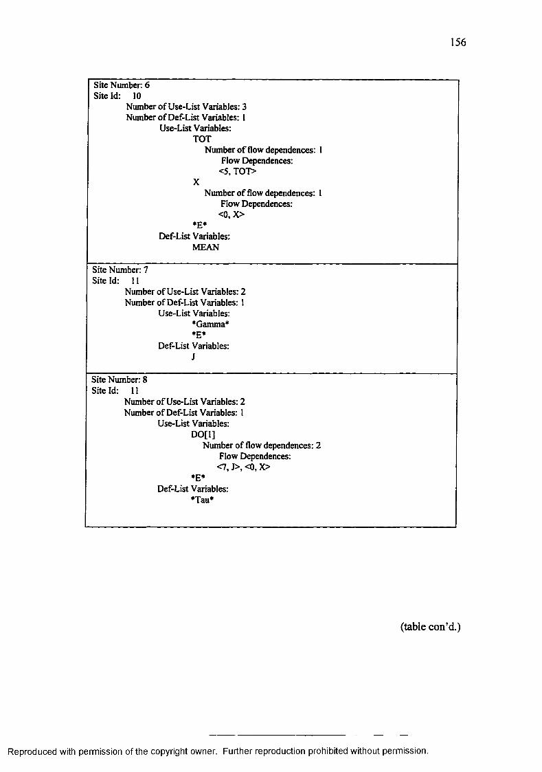
156
Site Number 6 Site Id: 10
Number o f Use-List Variables: 3 Number o f Def-List Variables: 1
Use-List Variables:TOT
Number o f flow dependences: 1 Flow Dependences:
<5, TOT>X
Number o f flow dependences: 1 Flow Dependences:
<0,X>*E*
Def-List Variables:MEAN
Site Number: 7 Site Id: 11
Number o f Use-List Variables: 2 Number o f Def-List Variables: 1
Use-List Variables: •Gamma**E*
Def-List Variables:J
Site Number: 8 Site Id: 11
Number o f Use-List Variables: 2 Number o f Def-List Variables: 1
Use-List Variables:DO[l]
Number of flow dependences: 2 Flow Dependences:
<7, J>, <0, X>♦E*
Def-List Variables:♦Tau*
(table con’d.)
Reproduced with permission of the copyright owner. Further reproduction prohibited without permission.

157
Site Number 9 Site Id: 12
Number o f Use-List Variables: 4 Number o f Def-List Variables: 1
Use-List Variables:J
Number o f flow dependences: 1 Flow Dependences:
<7, J>MEAN
Number o f flow dependences: 1 Flow Dependences:
<6, MEAN>EXPX
Number o f flow dependences: I Flow Dependences:
<0, EXPX>*E*
Number o f control dependences: 1 Control Dependences:<8, *Tau*>
Def-List Variables:IND
Site Number: 10 Site Id: 13
Number o f Use-List Variables: 5 Number o f Def-List Variables: 2
Use-List Variables:SUM
Number o f flow dependences: 1 Flow Dependences:
<2, SUM>IND
Number o f flow dependences: 1 Flow Dependences:
<9, IND>J
Number o f flow dependences: 1 Flow Dependences:
<7, J>*Gamma*
*E*Number o f control dependences: 1
Control Dependences:<8, *Tau*>
Def-List Variables:SUMJ
Number of loop dependences: 3 Loop Dependences:
____________________________<8, J>, <9, J>, <10, J>________
(table con’d.)
Reproduced with permission of the copyright owner. Further reproduction prohibited without permission.

158
Site Number 11Site Id: IS
Number o f Use-List Variables: 4Number o f Def-List Variables: 1
Use-List Variables:SUM
Number o f flow dependences: 1Flow Dependences:
<10, SUM>X
Number o f flow dependences: 1Flow Dependences:
<0,X>*Gamma*
*E*Def-List Variables:
STD
Site Number: 12Site Id: 15
Number of Use-List Variables: 7Number o f Def-List Variables: 0
Use-List Variables:X
Number o f flow dependences: 1 Flow Dependences:
<0,X>MEAN
Number o f flow dependences: 1Flow Dependences:
<6, MEAN>EXPX
Number o f flow dependences: 1Flow Dependences:
<0, EXPX>IND
Number o f flow dependences: I Flow Dependences:
<9, IND>TOT
Number o f flow dependences: 1 Flow Dependences:
<5, TOT>SUM
Number o f flow dependences: 1 Flow Dependences:
<10, SUM>STD
Number o f flow dependences: 1 Flow Dependences:
<11, STD>
Reproduced with permission of the copyright owner. Further reproduction prohibited without permission.

159
Table 5.29 Abstract site o f subroutine INPUT
Site Num ber Abstract Site Id: nil
Number o f Use-List Variables: 5 Number o f Def-List Variables: 4
Use-List Variables:MNEXPAEXPB*E*
Def-List Variables:MNEXPAEXPB
Table 5.30 Abstract site of subroutine PRINT
Site Num ber Abstract Site Id: nil
Number o f Use-List Variables: 5 Number o f Def-List Variables: 0
Use-List Variables: STDA STDB EXPA EXPB *E*
Table 5.31 Abstract site of function STD
Site Number: Abstract Site Id: nil
Number o f Use-List Variables: 2 Number o f Def-List Variables: 0
Use-List Variables:XEXPX
Reproduced with permission of the copyright owner. Further reproduction prohibited without permission.

160
Table 5.32 Textual description o f dependences o f MAIN
Total Number o f Sites: 6
Site Num ber 0 Site Id: 8
Number o f Use-List Variables: 0 Number o f Def-List Variables: 6
Def-List Variables:MNEXPAEXPBSTDASTDB
Site Num ber 1 Site Id: 9
Number o f Use-List Variables: 5 Number o f Def-List Variables: 4
Use-List Variables:MNEXPAEXPB*E*
Def-List Variables:MNEXPAEXPB
Site Number: 2 Site Id: 11
Number o f Use-List Variables: 4 Number o f Def-List Variables: 1
Use-List Variables:STDEXPA
Number of flow dependences: 1 Flow Dependences:
<1, EXPA>M
Number o f flow dependences: 1 Flow Dependences:
<1, M>*E*
Def-List Variables:STDA
(table con’d.)
Reproduced with permission of the copyright owner. Further reproduction prohibited without permission.

161
Site Number. 3 Site Id: 13
Number o f Use-List Variables: 4 Number o f Def-List Variables: 1
Use-List Variables:STDEXPB
Number o f flow dependences: 1 Flow Dependences:
<1, EXPB>N
Number o f flow dependences: 1 Flow Dependences:
<1, N>*E*
Def-List Variables:STDB
Site Number 4 Site Id: 14
Number o f Use-List Variables: 5 Number o f Def-List Variables: 0
Use-List Variables: STDA STDB EXPA EXPB *E*
(table con’d.)
Reproduced with permission of the copyright owner. Further reproduction prohibited without permission.

162
Site Number 5 Site Id: 14
Number o f Use-List Variables: 6 Number o f Def-List Variables: 0
Use-List Variables:M
Number o f flow dependences: 1 Flow Dependences:
<1, M>N
Number o f flow dependences: 1 Flow Dependences:
< l ,N >EXPA
Number o f flow dependences: 1 Flow Dependences:
<1, EXPA>EXPB
Number o f flow dependences: 1 Flow Dependences:<1, EXPB>
STDANumber o f flow dependences: 1
Flow Dependences:<2, STDA>
STDBNumber o f flow dependences: 1
Flow Dependences:<3, STDB>
Reproduced with permission of the copyright owner. Further reproduction prohibited without permission.

163
5.1.3 Parallel Design Recommendations
The Information Extractor (IE) and Dependence Analyzer (DANA) automati
cally produce program facts and dependence facts for each component in the design.
The program facts and dependence facts, which are based on CLIPS syntax, make use
of the class definitions outlined in Chapter 4 to create object instances.
The program facts o f subroutine INPUT are listed in Table 5.33. The program
facts are defined using the deffunction construct of CLIPS. The function “read-
objects-INPUT” is an user-defined function which consists of all the program facts for
subroutine INPUT. Documentation of the facts listed in Table 5.33 is done using
CLIPS commenting style. A line which starts with a semicolon is treated as a com
ment by CLIPS. The program facts include information about subroutine calls,
function calls, COMMON variables, complete variable description, state changes, DO-
loops, IF-conditions. A rule is defined at the end which invokes the function “read-
objects-INPUT”. The program facts similar to that of subroutine INPUT are gener
ated for all other components.
The dependence facts of the main program, MAIN are listed in Table 5.34.
The dependence facts are defined using the deffunction construct of CLIPS. The
function “read-Dependences-MAIN” is an user-defined function based on the deffunc
tion construct of CLIPS. The function “read-Dependences-MAIN” consists of all the
dependence facts for MAIN. The dependence facts include site information, flow data
dependences, loop data dependences and control dependences. A rule is defined at
the end which invokes the function “read-Dependences-MAIN” function. The pro
gram facts similar to that of MAIN are generated for all other components.
Reproduced with permission of the copyright owner. Further reproduction prohibited without permission.

164
Table 5.33 Program facts o f subroutine INPUT
(deffunction read-objects-INPUT 0 ; Program Facts for Subroutine INPUT ; Subroutine Calls Information
; Function Calls Information
; Labeled Commons Information
(bind ?x (make-instance (gensym) o f Labeled-Commons))(send ?x put-comp-name INPUT)
; Un Labeled Commons Information
(bind ?x (make-instance (gensym) o f Un-Labeled-Commons))(send ?x put-comp-name INPUT)
; Variable(s) Description
(bind ?x (make-instance (gensym) o f Locals (Var-Name M)(Type INTEGER)(Declared y)(Array n)(Non-Local y)))(send ?x put-comp-name INPUT)
(bind ?x (make-instance (gensym) of Locals (Var-Name N)(Type INTEGER)(Declared y)(Array n)(Non-Local y)))(send ?x put-comp-name INPUT)
(bind ?x (make-instance (gensym) o f Locals (Var-Name EXPA)(Type REAL)(Declared y)(Array y)(Dimensions 14)(Non-Local y)))(send ?x put-comp-name INPUT)
(bind ?x (make-instance (gensym) of Locals (Var-Name EXPB)(Type REAL)(Declared y)(Array y)(Dimensions 14)(Non-Local y)))
(send ?x put-comp-name INPUT)_______________________________________________________(table con’d.)
Reproduced with permission of the copyright owner. Further reproduction prohibited without permission.

165
(bind ?x (make-instance (gensym) o f Locals (Var-Name I)(Type INTEGER)(Declared n)(Array n)(Non-Local n)))(send ?x put-comp-name INPUT)
(bind ?x (make-instance (gensym) o f Locals (Var-Name J)(Type INTEGER)(Declared n)(Array n)(Non-Local n)))(send ?x put-comp-name INPUT)
; State Change Information
(bind ?x (make-instance (gensym) o f State-Changes (Line-Num 5)(Var-Name M)(Category *)))(send ?x put-comp-name INPUT)
(bind ?x (make-instance (gensym) o f State-Changes (Line-Num 6)(Var-Name I)(Rhs-Variables 1 14)(Category "->0-*D")))(send ?x put-comp-name INPUT)
(bind ?x (make-instance (gensym) o f State-Changes (Line-Num 7)(Var-Name EXPA)(Rhs-Variables I)(Category "->0-*D")))(send ?x put-comp-name INPUT)
(bind ?x (make-instance (gensym) o f State-Changes (Line-Num 10)(Var-Name N)(Category *)))(send ?x put-comp-name INPUT)
(bind ?x (make-instance (gensym) o f State-Changes (Line-Num 11)(Var-Name J)(Rhs-Variables 1 14)(Category "->1-*D")))(send ?x put-comp-name INPUT)
(table con’d.)
Reproduced with permission of the copyright owner. Further reproduction prohibited without permission.

166
(bind ?x (make-instance (gensym) of State-Changes (Line-Num 12)(Var-Name EXPB)(Rhs-Variables J)(Category ”->l-*D")))(send ?x put-comp-name INPUT)
; DO Loops Information
(bind ?x (make-instance (gensym) o f DO-Loops (DO-Start-Line 6)(DO-Last-Line 8)(DO-Label 15)(DO-Counting-Variable I)(DO-Initial-Value 1)(DO-Limit 14)(DO-Step nil)(DO-Nesting-Level 0)(DO-Prev-Type X)(DO-Prev-Id 0)))(send ?x put-comp-name INPUT)
(bind ?x (make-instance (gensym) o f DO-Loops (DO-Start-Line 11)(DO-Last-Line 13)(DO-Label 30)(DO-Counting-Variable J)(DO-Initial-Value 1)(DO-Limit 14)(DO-Step nil)(DO-Nesting-Level 0)(DO-Prev-Type X)(DO-Prev-Id 0)))(send ?x put-comp-name INPUT)
; IF Conditionals Information
; Subroutine Information(bind ?x (make-instance (gensym) of Subroutine(Name INPUT)(Sub-Formals M EXPA N EXPB)(num-formals 4)))(send ?x put-num-locals 6)(send ?x put-num-states 6)(send ?x put-num-do-Ioops 2)(send ?x put-comp-name INPUT))
(defrule Sub-INPUT = >
(read-objects-INPUT))
Reproduced with permission of the copyright owner. Further reproduction prohibited without permission.

167
Table 5.34 Dependence facts o f MAIN
; Dependence Knowledge Representation for Main Program MAIN (deffunction read-Dependences-MAIN 0
; Main Program Information
(bind ?x (make-instance (gensym) o f Main-Program (Name MAIN)))(send ?x put-num-sites 6)(send ?x put-comp-name MAIN)
; ------ Site Number 0 ------
(bind ?x (make-instance (gensym) o f Site (Site-Number 0)(Site-Id 1)(Number-of-Uls 0)(Number-of-Dls 6)(Number-of-Cds 0)))
(send ?x put-comp-name MAIN)
(bind ?x (make-instance (gensym) o f Def-Lists (Def-List-Name M)))
(send ?x put-Site-Number 0)(send ?x put-Site-Id 1)(send ?x put-comp-name MAIN)
(bind ?x (make-instance (gensym) o f Def-Lists (Def-List-Name N)))
(send ?x put-Site-Number 0)(send ?x put-Site-Id I)(send ?x put-comp-name MAIN)
(bind ?x (make-instance (gensym) o f Def-Lists (Def-List-Name EXPA)))
(send ?x put-Site-Number 0)(send ?x put-Site-Id 1)(send ?x put-comp-name MAIN)
(bind ?x (make-instance (gensym) o f Def-Lists (Def-List-Name EXPB)))
(send ?x put-Site-Number 0)(send ?x put-Site-Id 1)(send ?x put-comp-name MAIN)
(bind ?x (make-instance (gensym) o f Def-Lists (Def-List-Name STDA)))
(send ?x put-Site-Number 0)(send ?x put-Site-Id 1)(send ?x put-comp-name MAIN)
(table con’d.)
Reproduced with permission of the copyright owner. Further reproduction prohibited without permission.

168
(bind ?x (make-instance (gensym) o f Def-Lists (Def-List-Name STDB)))
(send ?x put-Site-Number 0)(send ?x put-Site-Id 1)(send ?x put-comp-name MAIN)
; ----- site Number 1 ------
(bind ?x (make-instance (gensym) o f Site (Site-Number 1)(Site-Id 9)(Number-of-UIs 5)(Number-of-DIs 4)(Number-of-Cds 0)))
(send ?x put-comp-name MAIN)
(bind ?x (make-instance (gensym) of Use-Lists (Use-List-Name M)))
(send ?x put-Site-Number 1)(send ?x put-Site-Id 9)(send ?x put-comp-name MAIN)
(bind ?x (make-instance (gensym) o f Use-Lists (Use-List-Name N)))
(send ?x put-Site-Number I)(send ?x put-Site-Id 9)(send ?x put-comp-name MAIN)
(bind ?x (make-instance (gensym) o f Use-Lists (Use-List-Name EXPA)))
(send ?x put-Site-Number I)(send ?x put-Site-Id 9)(send ?x put-comp-name MAIN)
(bind ?x (make-instance (gensym) o f Use-Lists (Use-List-Name EXPB)))
(send ?x put-Site-Number 1)(send ?x put-Site-Id 9)(send ?x put-comp-name MAIN)
(bind ?x (make-instance (gensym) o f Use-Lists (Use-List-Name *E*)))
(send ?x put-Site-Number 1)(send ?x put-Site-Id 9)(send ?x put-comp-name MAIN)
(bind ?x (make-instance (gensym) o f Def-Lists (Def-List-Name M)))
(send ?xput-Site-Number I)(send ?x put-Site-Id 9)(send ?x put-comp-name MAIN)_______________________________________________________
(table con’d.)
Reproduced with permission of the copyright owner. Further reproduction prohibited without permission.

169
(bind ?x (make-instance (gensym) o f Def-Lists (Def-List-Name N)))
(send ?x put-Site-Number 1)(send ?x put-Site-Id 9)(send ?x put-comp-name MAIN)
(bind ?x (make-instance (gensym) o f Def-Lists (Def-List-Name EXPA)))
(send ?x put-Site-Number 1)(send ?x put-Site-Id 9)(send ?x put-comp-name MAIN)
(bind ?x (make-instance (gensym) o f Def-Lists (Def-List-Name EXPB)))
(send ?x put-Site-Number I)(send ?x put-Site-Id 9)(send ?x put-comp-name MAIN)
; ------ Site Number 2 ------
(bind ?x (make-instance (gensym) o f Site (Site-Number 2)(Site-Id 11)(Number-of-UIs 4)(Number-of-Dls 1)(Number-of-Cds 0)))
(send ?x put-comp-name MAIN)
(bind ?x (make-instance (gensym) o f Use-Lists (Use-List-Name STD)))
(send ?x put-Site-Number 2)(send ?x put-Site-Id 11)(send ?x put-comp-name MAIN)
(bind ?x (make-instance (gensym) o f Use-Lists (Use-List-Name EXPA) (Number-of-Dus I)))
(send ?x put-Site-Number 2)(send ?x put-Site-Id 11)(send ?x put-comp-name MAIN)
(bind ?x (make-instance (gensym) o f Du-Edges (Du-Edges-Name EXPA) (Du-Dest-Site-Number 1)))
(send ?x put-Use-List-Name EXPA)(send ?x put-Site-Number 2)(send ?x put-Site-Id 11)(send ?x put-comp-name MAIN)
(table con’d.)
Reproduced with permission of the copyright owner. Further reproduction prohibited without permission.

170
(bind ?x (make-instance (gensym) o f Use-Lists (Use-List-Name M)(Number-of-Dus 1)))
(send ?x put-Site-Number 2)(send ?x put-Site-Id 11)(send ?x put-comp-name MAIN)
(bind ?x (make-instance (gensym) o f Du-Edges (Du-Edges-Name M) (Du-Dest-Site-Number I)))
(send ?x put-Use-List-Name M)(send ?x put-Site-Number 2)(send ?x put-Site-Id 11)(send ?x put-comp-name MAIN)
(bind ?x (make-instance (gensym) o f Use-Lists (Use-List-Name *E*)))
(send ?x put-Site-Number 2)(send ?x put-Site-Id 11)(send ?x put-comp-name MAIN)
(bind ?x (make-instance (gensym) o f Def-Lists (Def-List-Name STDA)))
(send 7 x put-Site-Number 2)(send ?x put-Site-Id 11)(send ?x put-comp-name MAIN)
; ------ site Number 3 ------
(bind ?x (make-instance (gensym) o f Site (Site-Number 3)(Site-Id 13)(Number-of-Uls 4)(Number-of-Dls 1)(Number-of-Cds 0)))
(send ?x put-comp-name MAIN)
(bind ?x (make-instance (gensym) of Use-Lists (Use-List-Name STD)))
(send ?x put-Site-Number 3)(send ?x put-Site-Id 13)(send ?x put-comp-name MAIN)
(bind ?x (make-instance (gensym) o f Use-Lists (Use-List-Name EXPB) (Number-of-Dus 1)))
(send ?x put-Site-Number 3)(send ?x put-Site-Id 13)(send ?x put-comp-name MAIN)
(table con’d.)
Reproduced with permission of the copyright owner. Further reproduction prohibited without permission.

171
(bind ?x (make-instance (gensym) o f Du-Edges (Du-Edges-Name EXPB) (Du-Dest-Site-Number 1)))
(send ?x put-Use-List-Name EXPB)(send ?x put-Site-Number 3)(send ?x put-Site-Id 13)(send ?x put-comp-name MAIN)
(bind ?x (make-instance (gensym) o f Use-Lists (Use-List-Name N)(Number-of-Dus 1)))
(send ?x put-Site-Number 3)(send ?x put-Site-Id 13)(send ?x put-comp-name MAIN)
(bind ?x (make-instance (gensym) o f Du-Edges (Du-Edges-Name N) (Du-Dest-Site-Number 1)))
(send ?x put-Use-List-Name N)(send ?x put-Site-Number 3)(send ?x put-Site-Id 13)(send ?x put-comp-name MAIN)
(bind ?x (make-instance (gensym) o f Use-Lists (Use-List-Name *E*)))
(send ?x put-Site-Number 3)(send ?x put-Site-Id 13)(send ?x put-comp-name MAIN)
(bind ?x (make-instance (gensym) o f Def-Lists (Def-List-Name STDB)))
(send ?x put-Site-Number 3)(send ?x put-Site-Id 13)(send ?x put-comp-name MAIN)
Site Number 4 ------
(bind ?x (make-instance (gensym) o f Site (Site-Number 4)(Site-Id 14)(Number-of-Uls 5)(Number-of-Dls 0)(Number-of-Cds 0)))
(send ?x put-comp-name MAIN)
(bind ?x (make-instance (gensym) o f Use-Lists (Use-List-Name STDA)))
(send ?x put-Site-Number 4)(send ?x put-Site-Id 14)(send ?x put-comp-name MAIN)_____________
(table con’d.)
Reproduced with permission of the copyright owner. Further reproduction prohibited without permission.

172
(bind ?x (make-instance (gensym) o f Use-Lists (Use-List-Name STDB)))
(send ?x put-Site-Number 4)(send ?x put-Site-Id 14)(send ?x put-comp-name MAIN)
(bind ?x (make-instance (gensym) of Use-Lists (Use-List-Name EXPA)))
(send ?x put-Site-Number 4)(send ?x put-Site-Id 14)(send ?x put-comp-name MAIN)
(bind ?x (make-instance (gensym) o f Use-Lists (Use-List-Name EXPB)))
(send ?x put-Site-Number 4)(send ?x put-Site-Id 14)(send ?x put-comp-name MAIN)
(bind ?x (make-instance (gensym) o f Use-Lists (Use-List-Name *E*)))
(send ?x put-Site-Number 4)(send ?x put-Site-Id 14)(send ?x put-comp-name MAIN)
; ------ Site Number 5 ------
(bind ?x (make-instance (gensym) o f Site (Site-Number54)(Site-Id 14)(Number-of-Uls 6)(Number-of-DIs 0)(Number-of-Cds 0)))
(send ?x put-comp-name MAIN)
(bind ?x (make-instance (gensym) o f Use-Lists (Use-List-Name M)(Number-of-Dus 1)))
(send ?x put-Site-Number 5)(send ?x put-Site-Id 14)(send ?x put-comp-name MAIN)
(bind ?x (make-instance (gensym) of Du-Edges (Du-Edges-Name M) (Du-Dest-Site-Number 1)))
(send ?x put-Use-List-Name M)(send ?x put-Site-Number 5)(send ?x put-Site-Id 14)(send ?x put-comp-name MAIN)
(table con’d.)
Reproduced with permission of the copyright owner. Further reproduction prohibited without permission.

173
(bind ?x (make-instance (gensym) o f Use-Lists (Use-List-Name N)(Number-of-Dus 1)))
(send ?x put-Site-Number 5)(send ?x put-Site-Id 14)(send ?x put-comp-name MAIN)
(bind ?x (make-instance (gensym) o f Du-Edges (Du-Edges-Name N)(Du-Dest-Site-Number 1)))
(send ?x put-Use-List-Name N)(send ?x put-Site-Number 5)(send ?x put-Site-Id 14)(send ?x put-comp-name MAIN)
(bind ?x (make-instance (gensym) of Use-Lists (Use-List-Name EXPA)(Number-of-Dus 1)))
(send ?x put-Site-Number 5)(send ?x put-Site-Id 14)(send ?x put-comp-name MAIN)
(bind ?x (make-instance (gensym) o f Du-Edges (Du-Edges-Name EXPA)(Du-Dest-Site-Number 1)))
(send ?x put-Use-List-Name EXPA)(send ?x put-Site-Number 5)(send ?x put-Site-Id 14)(send ?x put-comp-name MAIN)
(bind ?x (make-instance (gensym) o f Use-Lists (Use-List-Name EXPB)(Number-of-Dus 1)))
(send ?x put-Site-Number 5)(send ?x put-Site-Id 14)(send ?x put-comp-name MAIN)
(bind ?x (make-instance (gensym) o f Du-Edges (Du-Edges-Name EXPB)(Du-Dest-Site-Number 1)))
(send ?x put-Use-List-Name EXPB)(send ?x put-Site-Number 5)(send ?x put-Site-Id 14)(send ?x put-comp-name MAIN)
(bind ?x (make-instance (gensym) o f Use-Lists (Use-List-Name STDA)(Number-of-Dus 1)))
(send ?x put-Site-Number 5)(send ?x put-Site-Id 14)(send ?x put-comp-name MAIN)_______________________________________________________
(table con’d.)
Reproduced with permission of the copyright owner. Further reproduction prohibited without permission.

174
(bind ?x (make-instance (gensym) of Du-Edges (Du-Edges-Name STDA) (Du-Dest-Site-Number 2)))
(send ?x put-Use-List-Name STDA)
(send ?x put-Site-Number 5)
(send ?x put-Site-Id 14)
(send ?x put-comp-name MAIN)
(bind ?x (make-instance (gensym) of Use-Lists (Use-List-Name STDB) (Number-of-Dus 1)))
(send ?x put-Site-Number 5)
(send ?x put-Site-Id 14)
(send ?x put-comp-name MAIN)
(bind ?x (make-instance (gensym) of Du-Edges (Du-Edges-Name STDB) (Du-Dest-Site-Number 3)))
(send ?x put-Use-List-Name STDB)
(send ?x put-Site-Number 5)
(send ?x put-Site-Id 14)
(send ?x put-comp-name MAIN))
(defrule Dependences-MAIN= >
(read-Dependences-MAIN))
Reproduced with permission of the copyright owner. Further reproduction prohibited without permission.

175
Using the program facts and dependence facts, the CLIPS forward-chaining
inference procedure analyzed the dependences and produced the parallel design rec
ommendations for the sample program. A snapshot of the CLIPS based design
assistant is shown in Figure 5.6. A snapshot of the parallel design recommendations
derived by the CLIPS-based Design Assistant is shown in Figure 5.7. From Figure 5.7
it can be observed that the Design Assistant derived four parallel design recommenda
tions for the sample program. One of the unique features of the Design Assistant is the
explanation mechanism that provides the reasons for each parallel design recommen
dation. Henceforth we denote the parallel design recommendations as PDR-<Num>,
where <Num> is a number. For the sample program, <Num> ranges from 1 to 4.
From Figure 5.7 it can be observed that PDR-1, PDR-2, and PDR-3 correspond to in
ter-component parallelization for subroutine INPUT. PDR-4 corresponds to intra
component parallelization between the main program, MAIN and the user-defined
function STD.
PDR-1 states that the DO-loop identified by label ‘10’ in subroutine INPUT
may be parallelized. The reasons for arriving at PDR-1 are based on scenario 6 which
identified that the state change to variable EXPA defined within the loop depends only
on the loop index. PDR-2 states that the DO-loop identified by label ‘20’ in subrou
tine INPUT may be parallelized. The reasons for arriving at PDR-2 are based on
scenario 6 which identified that the state change to variable EXPB defined within the
loop depends only on the loop index. PDR-3 states that the computation of the DO-
loops identified by labels ‘10’ and ‘20’ in subroutine INPUT may be partitioned into
Reproduced with permission of the copyright owner. Further reproduction prohibited without permission.

176
parallel computations. The reasons for arriving at PDR-3 are based on scenario 6
which identified that there is no data flow between the two loops.
PDR-4 states that the function calls to STD from MAIN at relative line num
bers 11 and 13 may be parallelized. PDR-4 is based on scenario I which identified
that the actual parameters EXPA, M in function call to STD in line 11 are different
from the actual parameters EXPB, N in the function call to STD in line 13. The for
mal parameters EXPX, X are not modified in STD. Further, STD does not have
COMMON variables.
We introduced a graphical representation termed as PDR to represent parallel
design recommendations in Chapter 3. The PDR representation of subroutine INPUT
is shown in Figure 5.8. The PDR representation of the MAIN program is shown in
Figure 5.9. The textual description of the parallel design recommendations listed in
Figure 5.7 is tied to the graphical elements of PDR shown in Figures 5.8 and 5.9 using
a callout whose text is PDR-<Num>, where <Num> is a number.
Figures 5.8 and 5.9 along with textual parallel design recommendations listed
in Figure 5.7 collectively serve as a parallel design. The set of parallel design recom
mendations provided by the Design Assistant are useful in the reengineering the
original program to a parallel implementation. At this point, a suitable architecture
needs to be investigated. Most recommendations work well for shared memory archi
tectures. COMMON variable accessing is best resolved in shared memory
architectures.
Reproduced with permission of the copyright owner. Further reproduction prohibited without permission.

XELIPS f o r : CLIPS (V6.0 05 /12/93)CLIPS> (load ‘7 )> a n e2 /cs/c se rra /C lii> s /D esi(p i_ A ssis tan t/lo ad _ a il.c lp ")D efin in g deffunction : lo a d -a l lTRUECLIP5> ( lo a d -a l l)D efin ing d e fc la ss : Component D efin ing d e fc la ss : Kain-Progran D efin ing d e fc la ss : Subroutine D efin ing d e fc la ss : Function D efin ing d e fc la ss : C a lls D efin ing d e fc la ss : Func-C alls D efin ing d e fc la ss : DO-Loops D efin ing d e fc la ss : IF -C and itians D efin ing d e fc la ss : Locals D efin ing d e fc la ss : S tate-Changes D efin ing d e fc la ss : Labeled-Curarans D efin ing d e fc la ss : Hn-Labeled-Camaans D efin ing deffunction : e x tc a l ls D efin ing deffunction :D efin ing deffunction :D efin ing deffu n c tio n :D efin ing deffunction :D efin ing deffunction :D efin ing deffunction :D efin ing deffunction :D efin ing deffunction :D efin ing deffunction :D efin ing d e fc la ss : S i te D efin ing d e fc la ss : U se-L ists D efin ing d e fc la ss : D ef-L is ts D efin ing d e fc la ss : Du-Edges D efin ing d e fc la ss : Ud-Edges D efin ing d e fc la ss : Cd-Edges D efin ing deffunction : read-objects-MAIN D efin ing d efru le : s t a r t - i t +j D efin ing deffunction : read-ob]ects-INPDT D efin ing d efru le : Sub-INPUT +j D efin ing deffunction : read-objects-STD D efin ing d efru le : Fun-STD ♦]'D efin ing deffunction : read-ob j ects-PRINT D efin ing d e fru le : Sub-PRINT +j D efin ing deffunction : read-Dependences-KUN D efin ing d e fru le : Depndences-KAIN D efin ing deffunction : read-Dependences-INPOT
ex tfuns ge t-n u m b er-o f-ca lls g e t-n u ab er-o f-fu n cs g e t-n u n b e r-o f-lo c a ls g e t-n u n b e r-o f-s ta te s get-nunber-of-labeled^com sans get-num ber-of-un-labeled-cam m ons ge t-nunber-o f-do-loops g e t-n u n b e r-o f - if -c a n d itia n s
Figure 5.6 Snapshot of the CLIPS-based Design Assistant environment
Reproduced with permission of the copyright owner. Further reproduction prohibited without permission.

178
THDECLIPS> ( s t a r t - i t ). The Design A ssis tan t id e n tif ie d 4 components in th e o rig in a l design:
. MAIN
. Subroutine INPUT
. S ubroutine PRINT
. U ser-defined function STD
. P a ra lle l Design Recommendation 1. In t e r - Subroutine Parallelism has been id e n tif ie d fo r Subroutine
INPUT. The DO-loop id e n tif ie d by la b e l *10* may be p a ra lle l is e d . Reasoning: The s ta te change to v a ria b le EXPA defined v ith in the loop i d e n t if ied by Label '10 ' depends only on the loop index.
. P a ra lle l Design Recamaendatian 2. In ter-S ubrou tine P a ra lle lis e has been id e n t if ie d fo r Subroutine
INPUT. The DO-loop id e n tif ie d by la b e l *20* nay be p a ra lle l iz e d . Reasoning: The s ta te change to v a ria b le EXPB defined v ith in the loop id e n tif ie d by Label *20’ depends only an the loop index.
. P a ra lle l Design Recamaendatian 3. The computation o f the D0-loops id e n tif ie d by la b e ls ' 10* and ' 20'
nay be p a r ti t io n e d in to p a ra lle l am pu ta tions.Reasoning: There i s no data f lo v betoeen the too loop.Dependence analysis reveals th a t f in a l dela t io n o f EXPA i s a t S ite Number 4 and the f in a l d e fin itio n o f EXPB i s a t S ite Number 8.
. P a ra lle l Design Recamaendatian 4. Intra-Canponent P a ra lle lis e has been id e n t i f ie d among function c a l ls
to SID n o n MAIN a t Relative Line Numbers 11 and 13.Reasoning: Dependence analysis o f function SID reveals th a t the a c tu a l param eters EXPA, K in the function c a l l in Line Number 11 a re d if fe re n t from the ac tua l parameters EXPB, N in the function c a l l in Line Number 13. The formal param eters EXPX, X a re n o t m odified in function SID. Function SID does n o t have COMMON v a ria b le s .
CLIPS>
Figure 5.7 Snapshot of the parallel design recommendations in CLIPS
Reproduced with permission of the copyright owner. Further reproduction prohibited without permission.

179
Initialize Variables and Fork
PDR-3 PDR-3
Partition 1: DO[0] Partition 2: DO[l]
Initialize Variables and Fork
Initialize Variables and Fork
DO DO DO, DO
Join Join
PDR-1 PDR-2
Join, Return, End
Figure 5.8 PDR representation of subroutine INPUT
Reproduced with permission of the copyright owner. Further reproduction prohibited without permission.

Initialize Variables and Fork
PDR-4 PDR-4
Join
Figure 5.9 PDR representation of the sample program
Reproduced with permission of the copyright owner. Further reproduction prohibited without permission.

181
5.2 Analysis of NAS Kernels
In order to assess scalability of the reverse engineering toolkit (RETK), pro
grams of different sizes were analyzed. The information extractor (IE) was able to
handle programs of varying sizes ranging from 60-10000 lines. The maximum size of
a program analyzed by IE was CENTRM96 (a nuclear engineering based program)
which consisted of more than 10000 lines of code spanning over 100 subroutines and
functions.
Numerical Aerodynamic Simulation (NAS) kernel benchmark programs were
developed at NASA Ames Research Center for evaluating the performance of highly
parallel supercomputers [Bail 94]. The kernel programs, being benchmarks for paral
lel architectures, have a high potential for parallelization. The source code associated
with the kernel programs was used to elicit potential parallelism from the programs.
Source files o f the kernel programs which were written in FORTRAN-77 include the
block tridiagonal solver benchmark (APPBT.F), the lower/upper triangular solver
benchmark (APPLU.F), the pentadiagonal solver benchmark (APPSP.F). We have
arbitrarily selected the block tridiagonal solver benchmark (APPBT.F) for analysis.
5.2.1 Analysis of APPBT
The source code associated with the kernel program, APPBT.F, was input to IE
and the sequential design description of the program was extracted. Figures 5.10-5.14
show several snapshots of the design of APPBT. Figures 5.10-5.12 show metric in
formation which include number of lines in each module, number of commented lines,
and number o f blank lines. McCabe’s cyclomatic complexity for each module is
shown in Figure 5.13. From Figure 5.13 it can be observed that APPBT consists of 18
Reproduced with permission of the copyright owner. Further reproduction prohibited without permission.

182
components of which one is the main program and the rest are subroutines. Figure
5.14 shows a partial call graph of APPBT. Table 5.35 lists a textual description of the
complete call graph of the APPBT. Other design information including local and non
local variable description, state change information, DO-loop information, IF-
conditions information were extracted for each component. Since FORTRAN-77 al
lows the DO ... END DO construct explicit label names were generated for loops.
The label names are of the format RETK<Num> where <Num> is a unique number
within a module. The design attributes of each component were saved on disk for use
by the Dependence Analyzer (DANA). In addition to design information, program
facts for later use by the Design Assistant were generated for each component. The
dependence graph consisting of data and control dependences was generated for each
component in the design. DANA produced dependence facts of each component in the
design by reading the design attributes associated with the component. The depend
ence graph of each component is quite involved and is best viewed using xfig.
However, the partial dependence graph for subroutine SETBV is shown in Figure
5.15.
The parallel design recommendations for subroutine SETBV and subroutine
EXACT are listed in Tables 5.36. From Table 5.36 it can be observed that 3 parallel
design recommendations are derived for subroutine SETBV and 1 for subroutine EX
ACT. PDR-1 states that the nested DO-loops identified by ‘RETK1’ and ‘RETK2’
may be parallelized.
The reasons for arriving at PDR-1 are based on scenario 5 which identified that
the two calls to subroutine EXACT have different actual parameters in each call.
Reproduced with permission of the copyright owner. Further reproduction prohibited without permission.

183
Further, each call modifies COMMON variables at different locations. PDR-2 states
that the nested DO-loops identified by ‘RETK3’ and ‘RETK4’ may be parallelized.
The reasons for arriving at PDR-2 are based on scenario 5 which identified that
the two calls to subroutine EXACT have different actual parameters in each call.
Further, each call modifies COMMON variables at different locations. PDR-3 states
that the nested DO-loops identified by ‘RETK5’ and ‘RETK6’ may be parallelized.
The reasons for arriving at PDR-3 are based on scenario 5 which identified that
the two calls to subroutine EXACT have different actual parameters in each call.
Further, each call modifies COMMON variables at different locations. PDR-4 states
that the state changes defined in the DO-loop identified by RETK1 in subroutine EX
ACT may be partitioned.
The reasons for arriving at PDR-4 are based on scenario 6 which identified that
there is no flow data dependence among the state changes in the DO-loop. The PDR
representation of subroutine SETBV is shown in Figure 5.16. The PDR representation
of subroutine EXACT is shown in Figure 5.17.
The textual description of the parallel design recommendations listed in Table
5.36 is tied to the graphical elements of PDR shown in Figures 5.16 and 5.17 using a
callout whose text is PDR-<Num>, where <Num> is a number.
Reproduced with permission of the copyright owner. Further reproduction prohibited without permission.

Figure 5.10 Metric information o f NAS kernel program APPBT
Reproduced with permission of the copyright owner. Further reproduction prohibited without permission.

Figure 5.11 Metric information o f NAS kernel program APPBT
Reproduced with permission of the copyright owner. Further reproduction prohibited without permission.

Figure 5.12 Metric information o f NAS kernel program APPBT
Reproduced with permission of the copyright owner. Further reproduction prohibited without permission.

187
Figure 5.13 Cyclomatic complexity of the various components of theNAS kernel program APPBT
Reproduced with permission of the copyright owner. Further reproduction prohibited without permission.

Figure 5.14 Partial call graph of NAS kernel program APPBT
Reproduced with permission of the copyright owner. Further reproduction prohibited without permission.

189
Table 5.35 Complete call graph of the NAS kernel program APPBT
MAIN—>SETBV
—>EXACT —>EXACT —>EXACT —>EXACT —>EXACT —>EXACT
—>SETIV —>ERHS —>BADI
—>RHS—>MAXNORM —>L2NORM —>JACX —>BTRIDX —>JACY —>BTRIDY —>JACZ —>BTRIDZ —>MAXNORM —>L2NORM —>RHS—>MAXNORM —>L2NORM
—>ERROR—>EXACT —>EXACT
—>PINTGR —> VERIFY
Reproduced with permission of the copyright owner. Further reproduction prohibited without permission.

190
ISIZ1 I ISIZ2 IISIZ3 I C l I C2 I I/CL/a I/C U b I 1/C.7)Site 0: Def List
Site 1:
DQ->0 e
Site 2:
T 6
Site 3:
— Id o -m I z |-----
Site 4:
I J /CE.7C e
U(1.LLSite 5: EXACT
I iI J NZ /C E JC
-XT
Site 6: EXACT
Legend:
-► Flow Data Dependence
► Loop Data Dependence
-► Control Dependence
Figure 5.15 Partial dependence graph of subroutine SETB V
Reproduced with permission of the copyright owner. Further reproduction prohibited without permission.

191
Table 5.36 Parallel design recommendations for NAS program APPBT
• The Design Assistant identified 18 components in the original design
• Parallel Design Recommendation 1• Intra-Subroutine Parallelism has been identified for Subroutine
SETBV. The calls to subroutine EXACT within the nested DO-loop identified by RETK1 and RETK2 may be parallelized.Reasoning: Calls to subroutine EXACT have different actual parameters and each call modifies COMMON variables at different locations.
• Parallel Design Recommendation 2• Intra-Subroutine Parallelism has been identified for Subroutine
SETBV. The calls to subroutine EXACT within the nested DO-loop identified by RETK3 and RETK4 may be parallelized.Reasoning: Calls to subroutine EXACT have different actual parameters and each call modifies COMMON variables at different locations.
• Parallel Design Recommendation 3• Intra-Subroutine Parallelism has been identified for Subroutine
SETBV. The calls to subroutine EXACT within the nested DO-loop identified by RETK5 and RETK6 may be parallelized.Reasoning: Calls to subroutine EXACT have different actual parameters and each call modifies COMMON variables at different locations.
• Parallel Design Recommendation 4• Inter-Subroutine Parallelism has been identified for Subroutine EX
ACT. The state changes within the nested DO-loop identified by RETK1 may be parallelized.Reasoning: There is no data flow among the state changes. Dependence analysis reveals that the state changes are independent of each other.
Reproduced with permission of the copyright owner. Further reproduction prohibited without permission.

192
SETBV
1 f
RETK Process : Initialize Variables I = NY*NX and Fork
PDR-1
EXACT, EXACT* EXACT,
RETK Process: Join
RETK Process Initialize Variables m = NZ*NX and Fork
PDR-2
EXACT, EXACT- EXACT,• • •
RETK Process: Join
RETK Process Initialize Variables n = NZ*NX and Fork
PDR-3
EXACT, EXACT, EXACT,
RETK_Process : Jo in , Return, End
Figure 5.16 PDR representation of subroutine SETBV
Reproduced with permission of the copyright owner. Further reproduction prohibited without permission.

193
EXACT
RETK Process: Initialize
PDR-4
■Z.
Partition! Partition; • • •
RETK Process : Join, Return, End
Figure 5.17 PDR representation of subroutine EXACT
5.3 Summary
This chapter presented results of programs to test the methodology presented in
Chapter 3. The vehicle used to test-drive the methodology was RETK. Comprehen
sive results of a short sample program were presented. Results for the sample program
include extraction of a sequential design description, analysis and synthesis of the pro
gram dependence graph and derivation of parallel design recommendations. Summary
results of NAS kernel program APPBT were outlined. PDR notation was used to rep
resent parallel design recommendations for the programs.
Reproduced with permission of the copyright owner. Further reproduction prohibited without permission.

Chapter 6
Conclusions
This research was undertaken to 1) seek systematic solutions to the problem of
code migration from the sequential to the parallel processing environment, and 2) to
investigate and use reverse engineering techniques, dependence analysis, and knowl
edge-based techniques to provide automated support for the migration process. A
summary of the research is presented in Section 6.1. The contributions of this research
are summarized in Section 6.2. The extensions and future work possible in this re
search are explored in Section 6.3.
6.1 Summary
Migration of code from sequential environments to other environments, in
cluding parallel processing environments, is often done in an ad hoc manner. This
research presents a methodology that facilitates migration of code from the uni
processor to the parallel processing environments. By combining research in reverse
engineering, dependence analysis, and knowledge-based analysis, the methodology
provides a systematic approach for code migration.
This research encompasses three major areas; reverse engineering, dependence
analysis, and knowledge-based analysis. Chapter 2 presented a literature review of the
three major areas. Design recovery and identification of components are some of the
main issues in reverse engineering research. The notion of program dependence graph
194
Reproduced with permission of the copyright owner. Further reproduction prohibited without permission.

195
(PDG) [Ferr 87] and extensions to PDG by [Horw 90] and [Jack 94] were discussed.
The PDG model defined in [Jack 94] is particularly suited for reverse engineering re
search as it views procedures to be modular and dependences to be fine-grained. Even
the most trivial reverse engineering task is a “knowledge-intensive” process [Jarz 95].
Knowledge-based techniques discussed in Chapter 2 serve to provide intelligent sup
port in accepting or rejecting decisions.
In Chapter 3, we defined a methodology for design parallelization. The meth
odology consists of three main phases: Analysis, Synthesis, and Transformation. The
processes defined for the Analysis phase are to assess, segment, and extract the se
quential design description o f a FORTRAN program in the form of call graphs,
variable description, and state change information. The processes defined for the
Synthesis phase perform dependence analysis for each component and combine the
dependence analysis of each component to construct the PDG. The processes defined
for the Transformation phase use knowledge-based search and analysis to arrive at the
parallel design recommendations. PDR, a graphical representation scheme to repre
sent parallel design recommendations is defined.
Chapter 4 described the design and implementation of the reverse engineering
toolkit (RETK). RETK serves to establish a working model for the migration method
ology. Object-oriented design and implementation of the Information Extractor (IE)
which incorporates the processes of the Analysis phase were presented in detail. Ob
ject-oriented design and implementation of the Dependence Analyzer (DANA) which
incorporates the processes of the Synthesis phase were also presented. The design and
implementation of the Design Assistant (DA) to realize the processes of the Transfor
Reproduced with permission of the copyright owner. Further reproduction prohibited without permission.

196
mation phase were described. NASA’s C-Language Interface Production System
(CLIPS) and CLIPS Object-Oriented Language (COOL) were used to design the
knowledge base and inference procedure of DA. CLIPS-based knowledge representa
tion schemes were defined for representing program and dependence facts. We
provided formal definitions for a set o f six scenarios which use program and depend
ence facts of the original design to identify the parallelization potential in the original
design. The scenarios were encoded in the knowledge-base of DA using COOL.
Finally, in Chapter 5, we presented experimental results of actual code ana
lyzed by RETK. A comprehensive description of the results of the analysis was
presented for a short sample program. The results are indicative of the document
intensive nature of the output of the various phases of RETK. The results also include
analysis of a large NAS kernel benchmark program, APPBT. The effectiveness of
RETK, and thereby the migration methodology, to provide parallel design recommen
dations in a systematic and automated manner was also described.
6.2 Contributions
The undeniable advantages of parallel architectures and computing techniques
have precipitated the migration of code from sequential environments. However, the
migration process is often done in an ad hoc manner. This research provides system
atic approaches to the problem of code migration. The contributions of this research
are summarized below:
• A methodology that facilitates systematic migration of code from the uni-processor
to parallel processing environments is a significant and original contribution of this
Reproduced with permission of the copyright owner. Further reproduction prohibited without permission.

197
research because the methodology combines concepts from reverse engineering,
dependence analysis and knowledge-based analysis whereas most other research
efforts are based only on elaborate dependence analysis. In addition, the method
ology is scalable unlike most other labor intensive efforts.
• The definition of the processes and the associated algorithms for each phase in the
methodology advance the state of reverse engineering research. The processes of
each phase operate at the design level of the software system life cycle whereas the
processes in most other research efforts operate at the code level. The design level
of the software system life cycle provides a higher abstraction of the structure of an
existing system thereby facilitating information hiding, a key principle of software
engineering.
• A unique knowledge representation scheme for the representation of program facts
and dependence facts is an original contribution of this research. The knowledge
representation scheme defined is useful not only for parallelization efforts but also
for the maintenance of existing systems. The object-oriented knowledge repre
sentation scheme serves as a template for the instantiation of comprehensive
program and dependence information recovered and analyzed by the Analysis and
Synthesis phases respectively. For the purposes of maintenance, it is possible to
retrieve specific information from the knowledge base with the help of meaningful
queries.
• Since most legacy systems lack in proper documentation, the method that encodes
the software design into a knowledge-base is extremely useful. This research de
fines a unique method to encode the software design into a knowledge-base.
Reproduced with permission of the copyright owner. Further reproduction prohibited without permission.

198
• The scenarios in conjunction with general purpose functions that manipulate the
knowledge base constitute a unique rule base for the derivation of parallel design
recommendations.
• We defined a graphical notation to represent parallel design recommendations
called PDR in order to elucidate the parallelization potential of the original pro
gram. PDR makes explicit parallelizable segments in the original design using the
classical fork and join representation.
• Parallelization is a time-intensive process. To reduce the personnel costs involved
in the parallelization process, high degree of automated support is desirable.
Automated support reduces human input and thereby potentially reduces cost. A
valuable contribution of this research is the demonstration of the complete auto
mation of the migration methodology through RETK.
• This research uniquely incorporates an explanation mechanism to provide the rea
sons for arriving at a particular design recommendation thereby introducing
traceability for the recommendations.
• The migration methodology and RETK can be used to derive parallel design rec
ommendations from real-world code. Experimental results indicate that very large
programs can be handled effectively by RETK.
• Finally, the research contributes to the field of reverse engineering by the integra
tion of knowledge-base techniques. Irrespective of the design recovery procedure
used, the knowledge representation scheme defined in this research can be em
ployed to encode information into a knowledge-base for the eventual purpose of
parallelization.
Reproduced with permission of the copyright owner. Further reproduction prohibited without permission.

199
The process of re-engineering is most productive when considered as the com
plement to reverse engineering. Successful re-engineering of a system requires an in
depth understanding of the concepts and functionality of the system. The reverse en
gineering methodology defined in this dissertation serves as a prelude to re
engineering.
6.3 Future Research
The extensions for this work include:
• RETK can be modified to support other source languages like C. Since C allows
recursion and user-defined data types, the processes of the three phases of the
methodology should take into account the subtleties of the source language during
design and implementation..
• The derivation of architecture-specific and vendor-specific parallel design recom
mendations is a possible area of future research. A suitable knowledge
representation scheme needs to be explored to represent the topologies of different
parallel architectures in the knowledge-base of the Design Assistant. Specific
topological considerations include the number of autonomous processors, the in
terconnection network for communication among the processors, and the choice of
shared memory or distributed memory. For intra-component parallelization, the
processing associated with different components may be assigned to different
processors. Although all the processors in the configuration could be potentially
employed, the interconnection network places a limitation on the communication
of large data sets such as arrays. Shared memory configurations are suitable when
Reproduced with permission of the copyright owner. Further reproduction prohibited without permission.

the communication overhead is high while distributed memory configurations are
suitable for subroutines and functions that do not pass large arrays. Therefore, in
put data sets play a major role in the derivation of architecture-specific parallel
design recommendations. Also, when deriving design recommendations for ven
dor-specific parallel architectures, it may be necessary to incorporate domain and
application specific knowledge into the knowledge-base. Grouping of related do
mains and clustering of similar applications to arrive at generic knowledge-
representation templates would be very useful.
• In recent years, the client-server paradigm has been very well received by the in
dustry. Migration of legacy systems to client-server platforms with the help of the
methodology presented in this research is an area worthy of investigation.
• The application of the migration methodology to extract reusable frameworks from
legacy code is a possible area of future research.
• Reengineering tasks such as automatic code generation and automatic documenta
tion from parallel design recommendations and existing sequential code would be
an invaluable extension of this work.
Reproduced with permission of the copyright owner. Further reproduction prohibited without permission.

Bibliography
[Ache 94]
[Ache 95]
[Aho 77]
[Aike 93]
[Aike 94]
[ANSI 78]
[Bail 94]
[Beck 93]
[Bigg 94]
[Butl 95]
Achee, B.L., Carver, D.L., “A Greedy Approach to Object Identification in Imperative Code,” In Proceedings of 3rd Workshop on Program Comprehension, 1994.
Achee, B.L., Carver, D.L., “Identification and Extraction of Objects from Legacy Code,” In Proceedings of the IEEE Aerospace Applications Conference, Snowmass, CO, (February 1995), pp. 181-190.
Aho, A.V., Ullman, J.D., Principles o f Compiler Design, Addison- Wesley, 1977.
Aiken, P., Muntz, A., Richards, R., “A Methodology for Reverse Engineering DoD Legacy Information Systems,” In Proceedings of the Working Conference on Reverse Engineering, Baltimore, MD, (May 1993), pp. 180-191.
Aiken, P., Muntz, A., Richards, R., “DoD Legacy Systems: Reverse Engineering Data Requirements,” Communications of the ACM, Vol. 37, No.5 (May 1994), pp. 26-41.
American National Standards Institute, American National Standard Programming Language FORTRAN, ANSI X 3.9,1978, ANSI, NY.
Bailey, D., Barszcz, E., Barton, J., Browning, D., et. al. “The NAS Parallel Benchmarks,” NASA RNR Technical Report RNR-94-007, March 1994.
Beck, J., Eichmann, D., “Program and Interface Slicing for Reverse Engineering,” 1993 IEEE 15th International Conference on Software Engineering, pp. 509-518.
Biggerstaff, T.J., Mitbander, B.G., Webster, D.E., “Program Understanding and the Concept Assignment Problem,” Communications of the ACM, Vol. 37, No.5 (May 1994), pp. 72-83.
Butler, G., Grogono, P., Shingal, R., Tjandra, I., “Retrieving Information from Data Flow Diagrams,” In Proceedings of the Second Working Conference on Reverse Engineering, Toronto, Canada (July 1995), pp. 22-29.
201
Reproduced with permission of the copyright owner. Further reproduction prohibited without permission.

202
[Canf 93] Canfora, G., Cimitile, A., Munro, M., “A Reverse Engineering Methodfor Identifying Reusable Abstract Data Types,” In Proceedings of the Working Conference on Reverse Engineering, Baltimore, MD (May1993), pp. 73-82.
[Chik 90] Chikofsky, E.J., Cross II, J.H., “Reverse Engineering and Design Recovery: A Taxonomy,” IEEE Software, Vol. 13, No. 1 (January 1990), pp.13-17.
[Choi 90] Choi, S.C., Scacchi, W., “Extracting and Restructuring the Design ofLarge Systems,” IEEE Software, Vol. 13, No. 1 (January 1990), pp. 66-71.
[Clp 93a] CLIPS Reference Manual, , Volume I, “Basic Programming Guide,”JSC-25012, CLIPS Version 6.0, Software Technology Branch, NASA Johnson Space Center.
[Clp 93b] CLIPS Reference Manual, , Volume n, “Advanced ProgrammingGuide,” JSC-25012, CLIPS Version 6.0, Software Technology Branch, NASA Johnson Space Center.
[Clp 93c] CLIPS Reference Manual, , Volume HI, “Interfaces Guide,” JSC-25012, CLIPS Version 6.0, Software Technology Branch, NASA Johnson Space Center.
[Cuti 93] Cutillo, F., Fiore, P., Visaggio, G., “Identification and Extraction of“Domain Independent” Components in Large Programs,” In Proceedings of the Working Conference on Reverse Engineering, Baltimore, MD (May 1993), pp. 83-92.
[Dijk 76] Dijkstra, E.W., A Discipline o f Programming, Prentice-Hall, 1976.
[Edwa93] Edwards, H.M., Munro, M., “RECAST: Reverse Engineering fromCOBOL to SSADM Specification,” In Proceedings of the Working Conference on Reverse Engineering, Baltimore, MD (May 1993), pp. 44-45.
[Erra 96] Erraguntla, R.C., Carver, D.L., “A Reverse Engineering Toolkit for Design Recovery,” In Proceedings of the 2nd IEEE Aerospace Applications Conference, Snowmass, CO (February 1996), pp. 243- 252.
Reproduced with permission of the copyright owner. Further reproduction prohibited without permission.

203
[Ferr 87] Ferrante, J., Ottenstein, K.J., Warren, J.D., “The Program DependenceGraph and its use in Optimization,” ACM Transactions on Programming Languages and Systems, Vol. 9, No. 3 (July 1987), pp. 319-350.
[Flyn 72] Flynn, M.J., “Some Computer Organizations and Their Effectiveness,”IEEE Transactions on Computers, Vol. 21, No. 9 (September 1972), pp. 948-960.
[Ghez 91] Ghezzi, C., Jazayeri, M., Mandrioli, D., Fundamentals o f Software Engineering, Prentice-Hall, 1991.
[Hagh9l] Haghighat, M., Pluchronopoulos, C., “Symbolic Dependence Analysisfor High-Performance Parallelizing Compilers,” in Advances in Languages and Compilers for Parallel Processing (Edited by Nicoloau, A., et. al.), MIT Press, 1991.
[Hara90] Harandi, M.T., Ning, J.Q., “Knowledge-Based Program Analysis,”IEEE Software, Vol. 13, No. 1 (January 1990), pp.74-81.
[Harr 93] Harrison, W., Gens, C., Gifford, B., “pRETS: a parallel Reverse-engineering ToolSet for FORTRAN,” Software Maintenance: Research and Practice, Vol. 5 (1993), pp. 37-57.
[Holo 83] Holoien, M.O., Behforooz, A., Problem Solving and Structured Programming with Fortran-77, Brooks/Cole, 1983.
[Horw 90] Horwitz, S., Reps, T., Binkley, D., “Interprocedural Slicing Using Dependence Graphs,” ACM Transactions on Programming Languages and Systems, Vol. 12, No. I (January 1990), pp. 26-60.
[Hwan 93] Hwang, K., Advanced Computer Architecture: Parallelism, Scalability,Programmability, McGraw Hill, Inc., 1993.
[Ingl 94] Ingle, K.A., Reverse Engineering, McGraw-Hill, Inc., 1994.
[Jack 75] Jackson, M.A., Principles o f System Design, Academic Press, London,1975.
[Jack 94] Jackson, D., Rollins, E.J., “A New Model of Program Dependences forReverse Engineering,” Software Engineering Notes, SIGSOFT '94, ACM Press, Vol. 19, No. 5 (December 1994), pp. 2-10.
[Jarz 95] Jarzabek, S., Keam, T.P., “Design of a Generic Reverse EngineeringAssistant Tool,” In Proceedings of the Second Working Conference on Reverse Engineering, Toronto, Canada (July 1995), pp. 61-70.
Reproduced with permission of the copyright owner. Further reproduction prohibited without permission.

204
[Kara 95]
[Kuck 72]
[Kuck 78]
[Lano 93]
[Lilj 94]
[Love 93]
[Luts 95]
[Marc 86]
[Mark 94]
[MasP 91]
[Newc 93]
[Newc 95]
Karadimitriou, K., Tyler, J.M., Brener, N.E., “Reverse Engineering and Reengineering of a Large Serial System into a Distributed-Parallel Version,” In Proceedings of the 1995 ACM Symposium on Applied Computing, Nashville, TN (February 1995), pp. 191-197.
Kuck, D.J., Muraoka, Y., Chen, S-C., “On the Number of Operations Simultaneously Executable in Fortran-Like Programs and Their Resulting Speedup,” IEEE Transactions on Computers, Vol. C-21, No. 12 (December 1972), pp.1293-1322.
Kuck, D.J., The Structure o f Computers and Computations, Volume /., John Wiley & Sons, 1978.
Lano, K., Haughton, H., “Integrating Formal and Structured Methods in Reverse-Engineering,” In Proceedings of the Working Conference on Reverse Engineering, Baltimore, MD (May 1993), pp. 17-26.
Lilja, D. J., “Exploiting Parallelism Available in Loops,” IEEE Computer, February 1994, pp. 13-26.
Loveman, D.B., “High Performance Fortran,” IEEE parallel and distributed technology, February 1993, pp. 25-42.
Lutsky, P., “Automating Testing by Reverse Engineering of Software Documentation,” In Proceedings of the Second Working Conference on Reverse Engineering, Toronto, Canada (July 1995), pp. 8-12.
Marcotty, M., Ledgard, H., Programming Language Landscape, Science Research Associates, Inc., 1986.
Markosian, L., Newcomb, P., Brand, R., Burson, S., Kitzmiller, T., “Using an Enabling Technology to Reengineer Legacy Systems,” Communications of the ACM, Vol. 37, No. 5 (May 1994), pp. 58-90.
MasPar, “The MasPar Family Data-Parallel Computer,” Technical summary, MasPar Computer Corporation, Sunnyvale, CA, 1991.
Newcomb, P., Markosian, L., “Application of an Enabling Technology for Reengineering,” In Proceedings of the Working Conference on Reverse Engineering, Baltimore, MD (May 1993), pp. 222-230.
Newcomb, P., “Legacy System Cataloging Facility,” In Proceedings of the Second Working Conference on Reverse Engineering, Toronto, Canada (July 1995), pp. 52-60.
Reproduced with permission of the copyright owner. Further reproduction prohibited without permission.

205
[Ning93] Ning, J. Q., Engberts, A., Kozaczynski, W., “Recovering ReusableComponents from Legacy Systems by Program Segmentation,” In Proceedings o f the Working Conference on Reverse Engineering, Baltimore, MD (May 1993), pp. 64-72.
[Ning 94] Ning, J. Q., Engberts, A., Kozaczynski, W., “Automated Support forLegacy Code Understanding,” Communications of the ACM, Vol. 37, No. 5 (May 1994), pp. 50-57.
[Osbo 90] Osbome, W.M., Chikofsky, E.J., “Fitting Pieces to the MaintenancePuzzle,” IEEE Software, Vol. 13, No. 1 (January 1990), pp. 11-12.
[Pres 92] Pressman, R.S., Software Engineering: A Practitioner’s Approach,McGraw-Hill, Inc., Third Edition, 1992.
[Quil 94] Quilici, A., “A Memory-Based Approach,” Communications of theACM, Vol. 37, No. 5 (May 1994), pp. 84-93.
[Ric 88a] Rich, C., Waters, R.C., “Automatic Programming: Myths and Prospects,” Computer, Vol. 21, No. 8 (August 1988), pp. 40-51.
[Ric 88b] Rich, C., Waters, R.C., “The Programmer’s Apprentice: A ResearchOverview,” Computer, Vol. 21, No. 11 (November 1988), pp. 10-25.
[Rich 83] Rich, E., Artificial Intelligence, McGraw-Hill, Inc. 1993.
[Rich 90] Rich, C., Wills, L.M., “Recognizing a Program’s Design: A Graph-Parsing Approach,” IEEE Software, Vol. 13, No. 1 (January 1990), pp. 82-89.
[Ruga 90] Rugaber, S., Ombum, S.B., LeBlanc, Jr., R.J., “Recognizing DesignDecisions in Programs,” IEEE Software, Vol. 13, No. 1 (January 1990), pp. 46-54.
[Rumb91] Rumbaugh, J., Blaha, M., Premerlani, W., Eddy., F., Lorensen, W.,Object-Oriented Modeling and Design, Prentice-Hall, 1991.
[Scha 96] Schach, S.R., Classical and Object-Oriented Software Engineering, 3rdEdition, Irwin, 1996.
[Seba 93] Sebesta, R.W., Concepts o f Programming Languages, Benjamin/Cummings, Second. Edition, 1993.
[Sell 85] Sell, P.E., Expert Systems: A Practical Introduction, Halsted Press,London, 1985.
Reproduced with permission of the copyright owner. Further reproduction prohibited without permission.

206
[Ston 94]
[Wate 94]
[WCRE 93]
[WCRE 95]
[Weis 84]
[Wins 92]
[Zuyl 93]
Stone, H.S., High-Performance Computer Architecture, Addison- Wesley Publishing Company, 1994.
Waters, R.C., Chikofsky, E., “Reverse Engineering: Progress Along Many Dimensions,” Communications of the ACM, Vol. 37, No. 5 (May1994), pp. 22-25.
Proceedings of the Working Conference on Reverse Engineering Baltimore, MD (May 1993), IEEE Computer Society Press, 1993.
Proceedings of the 2nd Working Conference on Reverse Engineering Toronto, Canada (July 1995), IEEE Computer Society Press, 1993.
Weiser, M., “Prognim Slicing,” IEEE Transactions on Software Engineering,” Vol. SE-10 No. 4 (July 1984), pp. 352-357.
Winston, P. H., Artificial Intelligence, Addison-Wesley Publishing Company, Third Edition, 1992.
Zuylen H., (Ed.), The REDO Compendium of Reverse-Engineering for Software Maintenance, Wiley, 1993.
Reproduced with permission of the copyright owner. Further reproduction prohibited without permission.

Vita
Ravi Erraguntla was bom on October 5, 1965 in Visakhapatnam, India. Ravi
received the B.E. degree in Electronics and Communications Engineering from And
hra University, India and the M.E. degree in Electrical Engineering from Bharatiar
University, India. He worked as a Lecturer in Andhra University from 1989 - 1990.
Ravi came to the U.S. in Fall 90 and enrolled as a graduate student in Louisiana State
University. At LSU, Ravi received the M.S. degree in Nuclear Engineering and the
Ph.D. degree in Computer Science. During his stint at LSU he worked as a Graduate
Research Assistant in the Nuclear Science Center and the Department of Computer
Science. As part of his research assistantship he was involved as a Research Consult
ant for Thermalscan Inc., Baton Rouge and Medical Thermal Diagnostics, Baton
Rouge. He is presently working as a Consultant for Sabre Decision Technologies and
is located in the Dallas area.
207
Reproduced with permission of the copyright owner. Further reproduction prohibited without permission.

DOCTORAL EXAMINATION AND DISSERTATION REPORT
Candidate: Ravi Chandra Erraguntla
Major Field: Computer Science
Title of Dissertation: A Reverse Engineering Methodology For ExtractingParallelism From Design Abstractions
Approved:
Date of Examination:
August 29, 1996
Major Professor and Chairman
mDean of the Graduate School
EXAMINING COMMITTEE:
t-Sl/x —
Reproduced with permission of the copyright owner. Further reproduction prohibited without permission.