a review paper on intelligent led...
TRANSCRIPT

35 | P a g e
A REVIEW PAPER ON INTELLIGENT LED DRIVER
Preeti Srivastava1, Vanya Srivastava
2,
Tulika Parkash 3, Nikhil Kumar Gupta
4
1, 2 Students, Electrical Engineering Department Greater Noida Institutes of Technology, Gr.Noida, (India)
3 Student, Electronics Engineering Department IIMT College of Engineering, Gr.Noida, (India)
4Assistant Professor, Electrical Engineering Department Greater Noida Institutes of Technology, Gr. Noida, (India)
ABSTRACT
The objective of this paper is to the outstanding performance of the LED over the old type and even the
currently using light bulb, it is economically and most importantly environmental friendly to shift the main light
source to LEDs. The literature review on the future trend of lightning source, the advantages of the LED,
various types of LED driver . The main part of the LED driver is the converter circuit and the differences
between them are discussed. The methodology and how a complete smart LED driver is built, tested and
function is discussed. The working principle of the three major parts of the driver, i.e. converter, sensing and
feedback, is separate and thoroughly discussed. and presents the testing results on all the three major parts of
the LED driver. All of these parts are tested separately and are integrated together into a single smart LED
driver once they are functioning correctly.
I. OBJECTIVES
The objective of this paper is to the outstanding performance of the LED over the old type and even the
currently using light bulb, it is economically and most importantly environmental friendly to shift the main light
source to LEDs. In order to apply this without investing large amount of money, a smart LED driver which can
supply a constant current to the LED load directly from the main supply with sensing and control capabilities
are needed. In this project, a smart LED driver system with complete feedback and controlling sub system which
can supply constant current directly from the main to the LED string with the use of only power electronics
concept is aimed to develop. This driver will save more energy due to the efficiency of LED and this is inline
with the green environment concept. Other than this, with the flexibility brings by the 555 timer IC, the load
current of the LED can be control at any desired level. As compare to currently used light bulb, the LED light
bulb gives more advantages such as long life span, small in sizes, cheap in price, rich of colors and lastly which
is the most important current issue, the energy saving.
II. INTRODUCTION
A light-emitting diode (LED) is a semiconductor light source. LEDs are used as indicator lamps in many
devices and are increasingly used for other lighting. Introduced as a practical electronic component in
1962, early LEDs emitted low-intensity red light, but modern versions are available across
the visible, ultraviolet, and infrared wavelengths, with very high brightness.
36 | P a g e
A light emitting diode lamp is a solid state lamp which uses the light emitting diode (LED) as the source of
light. However a single LED supply not significant luminous flow of light as compare to the old type
incandescent and the newer compact fluorescent light bulb thus numbers of diodes are used together to provide
the sufficient light intensity.
The light emitting diode (LED) is known to be one of the best optoelectronic devices out of the lot. The device
is capable of emitting a fairly narrow bandwidth of visible or invisible light when its internal diode junction
attains a forward electric current or voltage. The visible lights that an LED emits are usually orange, red, yellow,
or green. The invisible light includes the infrared light. The biggest advantage of this device is its high power to
light conversion efficiency. That is, the efficiency is almost 50 times greater than a simple tungsten lamp. The
response time of the LED is also known to be very fast in the range of 0.1 microseconds when compared with
100 milliseconds for a tungsten lamp. Due to these advantages, the device wide applications as visual indicators
and as dancing light displays.
III. WORKING PRINCIPLE
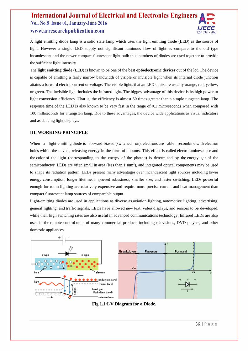
When a light-emitting diode is forward-biased (switched on), electrons are able recombine with electron
holes within the device, releasing energy in the form of photons. This effect is called electroluminescence and
the color of the light (corresponding to the energy of the photon) is determined by the energy gap of the
semiconductor. LEDs are often small in area (less than 1 mm2), and integrated optical components may be used
to shape its radiation pattern. LEDs present many advantages over incandescent light sources including lower
energy consumption, longer lifetime, improved robustness, smaller size, and faster switching. LEDs powerful
enough for room lighting are relatively expensive and require more precise current and heat management than
compact fluorescent lamp sources of comparable output.
Light-emitting diodes are used in applications as diverse as aviation lighting, automotive lighting, advertising,
general lighting, and traffic signals. LEDs have allowed new text, video displays, and sensors to be developed,
while their high switching rates are also useful in advanced communications technology. Infrared LEDs are also
used in the remote control units of many commercial products including televisions, DVD players, and other
domestic appliances.
Fig 1.1:I-V Diagram for a Diode.

37 | P a g e
IV. BASIC CHARACTERSTICS
Fig 1.2: Parts of an LED
Device Type :Passive, optoelectronic
Working principle:Electroluminescence
Invented : Nick Holonyak Jr. (1962)
First production : 1968[2]
Electronic symbol :
Fig 1.4: Electronic symbol
Pin configuration: Anode and Cathode
Construction:At the heart of LED construction is the p-n junction which functions as a semiconductor diode.
Every LED contains a p-type semiconductor (electron rich) and n-type semiconductor (electron deficient) with a
transition layer between them known as the p-n junction.Connecting the LED to an energy source results in the
flow of current from the p-side (anode) to the n-side (cathode). When the volt passes through an LED circuit, it
encourages electrons to recombine with electron holes, which then releases energy as photons or light. The
voltage across the p-n junction must be in the correct direction (forward-biased) in order for an LED to
illuminate. A reverse-biased polarity will result in little current and no illumination.
Fig 1.5 LED Construction

38 | P a g e
RGB systems
Fig 1.7:Combined spectral curves for blue, yellow-green, and high-brightness red solid-state
semiconductor LEDs.
Phosphor-based LEDs
Fig 1.8: Spectrum of a “white” LED clearly showing blue light directly emitted by the GaN-
based LED (peak at about 465 nm) and the more broadband Stokes-shifted light emitted by the
Ce3+
:YAG phosphor, which emits at roughly 500–700 nm.
This method involves coating LEDs of one color (mostly blue LEDs made of InGaN) with phosphor of different
colors to form white light; the resultant LEDs are called phosphor-based white LEDs. Depending on the color
of the original LED, phosphors of different colors can be employed. If several phosphor layers of distinct colors
are applied, the emitted spectrum is broadened, effectively raising the color rendering index (CRI) value of a
given LED.
Among the challenges being faced to improve the efficiency of LED-based white light sources are the
development of more efficient phosphors as well as the development of more efficient green LEDs. The
theoretical maximum for green LEDs is at 683 lumens per watt but today few Green LEDs exceed even 100
lumens per watt. Today the most efficient yellow phosphor is still the YAG phosphor,with less than 10% Stoke
shift loss. Losses attributable to internal optical losses due to re-absorption in the LED chip and in the LED
packaging itself account typically for another 10% to 30% of efficiency loss.

39 | P a g e
V. LED TECHNOLOGY BREAKTHROUGHS
Recent innovations in the manufacturing of the die material and packaging have resulted in ultra high brightness
capabilities. The use of new materials for the substrate have allowed for improved thermal conductivity which
allows for higher power consumption and net light output. This Increase in light output has enabled new
applications for LEDs such as automotive lighting, traffic signals, and more recently, television displays. An
example of these new structures is illustrated.
Fig 1.9: New basic LED Structure
Significant improvements in the production of Aluminum-Indium-Gallium-Phosphide (AlInGaP) and Indium-
Gallium-Nitride structures have allowed for improved brightness in green and blue specifically. Additional
colors such as amber and cyan are also being developed at a rapid pace. These improvements enable system
designs that can produce better color fidelity at near equivalent brightness to common lamp-based technologies
with longer lifetimes. Additional performance enhancements include system level features like instant on, no
mercury, no color refresh artifacts, dynamically adjustable brightness, and improved color gamuts. Figure
illustrates the gamut area for LED illumination as compared to the common reference standard (Rec. 709).
Fig1.10: LED Color Gamut

40 | P a g e
LED illumination provides a much larger color gamut (as much as 40% or more than the HDTV color standard
[Rec. 709]), providing more accurate color fidelity. These performance attributes can be quite appealing for
television applications where long life and excellent color fidelity are required. As LEDs continue to advance,
their impact on television applications could be significant.
5.1 Types
Fig1.12: Types of LED
LEDs are produced in a variety of shapes and sizes. The 5 mm cylindrical package (red, fifth from the left) is the
most common, estimated at 80% of world production. The color of the plastic lens is often the same as the
actual color of light emitted, but not always
VI. LITERATURE REVIEW
As times moves, the technology of LED become more advance and until now LED not only replacing those old
generations’ light source but also expend to other area such as LCD display back light and aircraft instrument
panel lighting.
In general there are two common types of LED panels which are the conventional and surface mounted device
(SMD). The LED panel is the base of LEDs bulb which used for categorize the LED. Both of the panel comes
with large color profile. This means that both of them can generate different color for different application. Any
color can be generated with the mixing of different intensity of the three primary colors which are the red, green
and blue. For both of the panel, three primary colors’ diodes are driven together to form a full color pixel (Ning
Bo xinyi electronic co., 2007). When they are arranged properly, any visual effect and even to write a word in
the signboard become possible.
Fig 2.1: Conventional LED Fig 2.2: LED traffic light

41 | P a g e
VII. ADVANTAGES OF USING LED
7.1 Long Life Span
The operational time for a white LED lamp under normal condition is around100,000 hours. This is 4166 days
of 24 hours nonstop operating under a normal condition. Basically one LED bulb can last for 22 years without
any maintenance and replacement.
The working lifetime of an incandescent bulb is approximately 5000 hours. This means that one may need to
change 20 times of the incandescent light bulb butonly once for the LED bulb. This not only saves the time but
also the cost for maintenance.
7.2 Sizes
For the size wise, a LED is not questionable very small as compare to the older generations’ entire bulb.
Although a single LED bulb does not provide a very significant good luminous flow of light but they can be
connected in string and yet consuming less energy to provide the same brightness as the fluorescent lamp. The
string connected LED adds flexibility for those who have different requirement on the brightness based on their
preference. Even when the LEDs are connected in a string the size is still relatively smaller than the older
generation bulb. The benefit of smaller bulb is that the space can be fully utilize while providing better visual
effect and in advance this gives additional advantage of building different shapes of LED bulb (Michael
Lane,2000).
Fig 2.3: Size difference for a LED and compact fluorescent bulb
7.3 Cost
Generally the installation cost has not much different for LED and the traditional bulb. Using the fluorescent
bulb, the actual cost is the replacement cost, labour expanses and also the time. As I mentioned in Section 2.2.1,
a LED has around 20 times longer lifespan as compare to the fluorescent bulb, this means that the cost of using
LED bulb is 20 times lower. All of these factors become significant when they come in large amount. Let us
take an example of UTAR Setapak campus. There are more than 300 fluorescent bulbs and tubes in only the SA
block and up to two thousand plus for the whole campus. The cost to replace few thousands of bulbs within the
campus, hire technicians and spending time can be virtually eliminated or at least reduce by 200 % with the use
of the LED bulb.

42 | P a g e
7.4 Colors
Now a day the LEDs are available in a big range of color including the white light. White light is produced by
the mixing of three primary colors; red, green and blue and it provides the maximum luminous flow. With
proper intensity mixing of the three primary colors, dramatic range of color and color changing effect can be
produced such as color washing, cross fading and random color.
VIII. INTELLIGENT LED DRIVER
Many early adopters of LED technologies for lighting started out thinking the move would be a simple
evolutionary step but quickly found out that the move was revolutionary. They discovered that they needed
serious engineering disciplines to implement new electronics, optics and thermal technologies. Many who took
the initial steps in electronics produced sub-par products and had to redesign their products to get more efficient
and optimal results. Others outsourced their designs to competent power and analog engineers who spent a
lifetime learning how to drive the power circuits and constant current required by LEDs. The electronics
required have been called lighting ballasts or power supplies but are commonly and collectively referred to as
LED drivers.
Nowadays, human has become too busy and he is unable to find time even to switch the lights wherever not
necessary. This can be seen more effectively in the switch the lights wherever not necessary.
This can be seen more effectively in the evening before the sun sets and they are switched off the next day
morning after there is sufficient light on the roads. But the actual timings for these street lights to be switched on
are when there is absolute darkness.
With this, the power will be wasted up to some extent. This project gives the best solution for electrical power
wastage. Also the manual operation of the lighting system is completely eliminated.
Generally the light lamps is operating by manually operation and by the mainly men power so that in this system
the wastage of the time and also wastage of the electric power , so that for the reduced this problem we find the
way that this street light is operating by the automatic control means by using the IC555.
8.1 Led Driver Intelligence
This circuit needs no manual operation for switching ON and OFF When there is need of light. It detects itself
weather there is need for light or not. When darkness rises to a certain value then automatically street light is
switched ON and when there is other source of light i.e. day time, the street light gets OFF.
The sensitiveness of the light lamp can also be adjusted. In our project we have used four LED for indication of
bulb but for high power switching one can connect Relay (electromagnetic switch) at the output of pin 3 of I.C
555. Then it will be possible to turn ON/OFF any electrical appliances connected all the way through relay.
8.2 Principle
This circuit uses a popular timer I.C 555. I.C 555 is connected as comparator with pin-6 connected with positive
rail, the output goes high(1) when the trigger pin 2 is at lower then 1/3rd level of the supply voltage. Conversely
the output goes low (0) when it is above 1/3rd level. So small change in the voltage of pin-2 is enough to change
the level of output (pin-3) from 1 to 0 and 0 to 1.

43 | P a g e
The output has only two states high and low and cannot remain in any intermediate stage. It is powered by a 6V
battery for portable use. The circuit is economic in power consumption. Pin 4, 6 and 8 is connected to the
positive supply and pin 1 is grounded. To detect the present of an object we have used LDR and a source of
light.
IX. PHOTO RESISTOR OR LDR
A photo resistor or light dependent resistor (LDR) is a resistor whose resistance decreases with increasing
incident light intensity; in other words, it exhibits photoconductivity. It can also be referred to as a
photoconductor or CdS device, from "cadmium sulfide," which is the material from which the device is made
and that actually exhibits the variation in resistance with light level. Note that although CdS is a semiconductor,
it is not doped silicon
Fig 5.1: symbol for a photo resistor fig 5.2 A light dependent resistor
A photo resistor is made of a high resistance semiconductor. If light falling on the device is of high enough
frequency, photons absorbed by the semiconductor give bound electrons enough energy to jump into the
conduction band. The resulting free electron (and its hole partner) conduct electricity, thereby lowering
resistance
X. WORKING
When light falls on the LDR then its resistance decreases which results in increase of the voltage at pin 2 of the
IC 555. IC 555 has got comparator inbuilt, which compares between the input voltage from pin2 and 1/3rd
of the
power supply voltage.
When input falls below 1/3rd then output is set high otherwise it is set low. Since in brightness, input voltage
rises so we obtain no positive voltage at output of pin 3 to drive relay or LED, besides in poor light condition we
get output to energize.
LDR is a special type of resistance whose value depends on the brightness of the light which is falling on it. It
has resistance of about 1 mega ohm when in total darkness, but a resistance of only about 5k ohms when
brightness illuminated.
It responds to a large part of light spectrum. We have made a potential divider circuit with LDR and 100K
variable resistance connected in series. We know that voltage is directly proportional to conductance so more
voltage we will get from this divider when LDR is getting light and low voltage in darkness.

44 | P a g e
This divided voltage is given to pin 2 of IC 555. Variable resistance is so adjusted that it crosses potential of
1/3rd in brightness and fall below 1/3rd
in darkness.
Sensitiveness can be adjusted by this variable resistance. As soon as LDR gets dark the voltage of pin 2
drops1/3rd of the supply voltage and pin 3 gets high and LED or buzzer which is connected to the output gets
activated.
Photo resistors come in many different types. Inexpensive cadmium sulphide cells can be found in many
consumer items such as camera light meters, street lights, clock radios, alarm devices, outdoor clocks,solar
street lamps and solar road studs etc.
They are also used in some dynamic compressors together with a small incandescent lamp or light emitting
diode to control gain reduction and are also used in bed lamps etc.
XI. MAIN CIRCUIT
a)Power supply:AC power is converted into DC with the help of rectifier circuit.
Fig 5.4 Bridge Rectifier
b) Switch: Any general purpose switch can be used. Switch is used as circuit breaker.
c) LDR(Light Depending Resistance):It is a special type of resistance whose value depends on the brightness of
light which is falling on it. It has resistance of about 1mega ohm when in total darkness, but a resistance of only
about 5k ohms when brightness illuminated. It responds to a large part of light spectrum.
d) LED(Light Emitting Diode):A diode is a component that only allows electricity to flow one way. It can be
thought as a sort of one way street for electrons. Because of this characteristic, diodes are used to transform or
rectify AC voltage into a DC voltage. Diodes have two connections, an anode and a cathode. The cathode is the
end on the schematic with the point of the triangle pointing towards a line.
In other words, the triangle points toward that cathode. The anode is, of course, the opposite end. Current flows
from the anode to the cathode. Light emitting diodes, or LEDs, differ from regular diodes in that when a voltage
is applied, they emit light. This light can be red (most common), green, yellow, orange, blue (not very common),
or infrared.
LEDs are used as indicators, transmitters, etc. Most likely, a LED will never burn out like a regular lamp will
and requires many times less current. Because LEDs act like regular diodes and will form a short if connected
between + and -, a current limiting resistor is used to prevent that very thing. LEDs may or may not be drawn
with the circle surrounding them.

45 | P a g e
(e) Variable resistance:Resistors are one of the most common electronic components. A resistor is a device that
limits, or resists current. The current limiting ability or resistance is measured in ohms, represented by the Greek
symbol Omega.
Variable resistors (also called potentiometers or just “pots”) are resistors that have a variable resistance. You
adjust the resistance by turning a shaft. This shaft moves a wiper across the actual resistor element. By changing
the amounts of resistor between the wiper connection and the connection (s) to the resistor element, you can
change the resistance.
We will often see the resistance of resistors written with K (kilohms) after the number value. This means that
there are that many thousands of ohms. For example, 1K is 1000 ohm, 2K is 2000 ohm, 3.3K is 3300 ohm, etc.
This simply means million. Resistors are also rated by their power handling capability. This is the amount of
heat the resistor can take before it is destroyed. The power capability is measured in W (watts) Common
wattages for variable resistors are 1/8W, 1/4W, 1/2W and 1W. Anything of a higher wattage is referred to as a
rheostat.
f) PCB (Printed Circuit Board):With the help of P.C.B it is easy to assemble circuit with neat and clean end
products. P.C.B is made of Bakelite with surface pasted with copper track-layout. For each components leg, hole
is made. Connection pin is passed through the hole and is soldered.
D1
1N1202C
D2
1N1202C
C11uF
D3
1N1202C
VCC
OUT
U1555_TIMER_RATED
GND
DIS
RST
THR
CON
TRI
C21uF C3
1uF
R2
1kΩ
R1
1kΩ
Key=A50%
U2
741
3
2
4
7
6
51
U4
741
3
2
4
7
6
51
R41kΩ
R51kΩ
R3
1kΩ
Key=A50%
R61kΩ
U3MC78L05ACD
LINE VREG
COMMON
VOLTAGE
X1
5 V
X3
5 V
11
15
12
13
10
7
4
D4
1N1202C
V1
220 Vrms
50 Hz
0°
T1
AIR_CORE_XFORMER
1
3
5
6
0
XMM1
XMM2
14
8
2
Fig 5.4 Main Circuit Diagram

46 | P a g e
11.1 Working
Step 1: An empty capacitor
By this time, the capacitor is considered to be empty. Because of that, the input - of the lower comparator will
be more negative than the input + of it. This will generate a high (1) signal at the output of this comparator that
will set the flip flop. The flip flop will finally set high the Q output.
Step 2: Filling the capacitor
This is the first critical time of the operation cycle. The capacitor will start increasing it's load from within the
resistors R1 + R2. During all this time, the Q output will remain high due to the latch of the flip flop, however
the output of the lower comparator will have become low as the - input will have become more positive than the
+ input of the comparator.
Step 3: A filled capacitor
Well, not quite filled, but almost filled. Step 3 will occur when the capacitor has equal to the 2/3 of the Vcc
voltage charge. When it does, the input + of the upper comparator will become more positive than it's input -.
This will cause the upper comparator's output to become high state and reset the flip flop. Reseting the flip flop
will cause the output of the 555 to return to low state.
Step 4: Emptying the capacitor
When the previous step occurred, the upper comparator reseted the flip flop and the output Q of the flip flop
became low. the reverse Q output will therefore become high. This signal is applied to the base of the transistor
that it's colloector is the input 7 of the 555. The transistor's CE will become conductive, and the capacitor will
start discharging from within R2 and the transistor.
When the capacitor is fully discharge, step 1 will occur again and so on and so on...
Pulse time calculations
As described before, the two stated of the output, the high and the low state, depends on the values of the R1, R2
and the capacitor C. Moreover, the high state depends on the R1+R2 and the capacitor C, and the low state
depends on the R2 and the C. The formulas for calculating the oscillation frequency and the duty cycle are as
follows:
The High output state that depends on both R1 + R2, is:
THIGH = 0.67 x (R1 + R2) x C (result in Seconds)
The Low output state depends only on R2 and is:
TLOW = 0.67 x R2 x C (result in Seconds)
To calculate the oscillation frequency, we add THIGH and TLOW.
TTOTAL = T1 + T2 = 0.67 x (R1 + R2) x C + 0.67 x R2 x C
TTOTAL = 0.67 (R1 + 2 x R2) x C
The TTOTAL is actually the period of the oscillation measured in seconds. Therefore, the frequency is:
F = 1 / TTOTAL => F = 1
0.67 (R1 + 2 x R2) x C

47 | P a g e
XII. CONCLUSION
LED lighting applications can be subcategorized in to three groups; <25W, 25W-100W and 100W. It is fair to
say the <25W LED lighting applications can be usually found in portable handheld products such as PMPs, or
even automotive infotainment displays. Similarly, 25W-100W LED lighting applications can be found in
automotive headlamps and architectural lighting applications. And finally, 100W LED lighting applications will
commonly occur in large panel LCD-TVs, video walls and industrial lighting.
Thus, it is useful to think of these LED lighting power levels as they relate to some of these applications as the
best way to discuss the challenges of the technical implementation and commercial viability aspects.
< 25W LED Lighting – Handheld Devices
Many of today’s mobile phones have a built-in digital camera capable of high-resolution still and video images.
Gains in camera performance have also created the need for a high power white light source for camera use
indoors or in dim ambient light. White LEDs have emerged as the primary light source in cellular phones
equipped with cameras .Since they possess a desirable combination of features for the modern cell-phone
designer: small size, high light output, and the ability to provide both “flash” and continuous “video” subject
lighting. High output power LEDs have been developed specifically for use as integrated camera lights.
REFERENCES
[1]. Alan J. Heeger, Alan G. MacDiarmid and Hideki Shirakawa The Royal Swedish cademy of Sciences,
Sweden,http://www.nobel.se/chemistry/laureates/2000/public.html , accessed November 8, 2002.
[2]. Lumen Maintenance of White Luxeon Power Light Sources, http://www.lumileds.com/pdfs/AB07.PDF,
Accessed November 4, 2002.
[3]. Pang, Grantham; Kwan, Thomas; Liu Hugh; Chan, Chi-Ho, “LED traffic light as communications
device”, University of Hong Kong ,Hong Kong, 1999.
[4]. Data Display Products, http://www.ddp-leds.com/applicationnotes.htm, Accessed November 10, 2002
[5]. Pang, Grantham; Kwan, Thomas; Liu Hugh; Chan, Chi-Ho, “Optical wireless based on high brightness
visible LEDs”, University of Hong Kong ,Hong Kong,1999.
[6]. Pang, Grantham; Kwan, Thomas; Liu Hugh; Chan, Chi-Ho, “Optical wireless based on high brightness
visible LEDs”, University of Hong Kong ,Hong Kong, 1999.
[7]. IBM Corporation, http://www.almaden.ibm.com/st/projects/oleds/ , Accessed November8, 2002.
[8]. McGraw, Daniel, Medical Applications of Light Emitting Diodes, Photonics East, Boston MA, 2000,
http://www.spie.org/web/meetings/programs/pe00/courses/SC195.html, Accessed November 8, 2002.
[9]. Reid, D.T.; Padgett M.; McGowan C.; Sleat, W.E.; Sibett, W., “Light Emitting Diodes as measurement
devices for fem to second laser pulses”, Optic Letters Feb. 16, 1996. v22.
[10]. Light Emitting Diodes (LED), Australian Photonics
CRC,http://www.vislab.usyd.edu.au/photonics/devices/semicdev/led0.html, Accessed November 10,
2002