a simulation environment for hierarchical process chains
TRANSCRIPT

A Simulation Environment for HierarchicalProcess Chains based on OMNeT++
Falko Bause, Peter Buchholz, Jan Kriege, Sebastian VastagTU Dortmund, Informatik IVD-44221 Dortmund, Germany{falko.bause,peter.buchholz,jan.kriege,sebastian.vastag}@udo.edu
Author prepared version of a paper published in
SIMULATION, Vol. 86, No. 5-6, 2010.
http://dx.doi.org/10.1177/0037549709104236

A Simulation Environment for Hierarchical Process Chains based on
OMNeT++∗
Falko Bause, Peter Buchholz, Jan Kriege, Sebastian Vastag
TU Dortmund, Informatik IV
D-44221 Dortmund, Germany
{falko.bause,peter.buchholz,jan.kriege,sebastian.vastag}@udo.edu
Abstract
OMNeT++ is a discrete event simulation environment primarily designed for communication networks. In this paper we
present an approach to enableOMNeT++ to simulate complex hierarchical process chains. Process chains are a common
modeling paradigm in the logistics area for the analysis andoptimization of large process chains and have been intensely
used in many practical applications. Their evaluation is supported by theProC/B toolset, a collection of software tools for
modeling, analysis, validation and optimization of process chains. Here we describe howOMNeT++ has been integrated as
a new simulation engine into the toolset. The integration has to get over some core problems to allow a smooth interaction
betweenOMNeT++ and the other tools: In particular, theOMNeT++ model description of the logistics network should
be kept manageable, it should reflect the entire model structure and non-standard performance figures, being relevant for
an economic evaluation, should be ascertainable in order tosatisfy the specific needs of the application area. The paper
highlights the main steps of the automatic transformation of a hierarchical process chain model into a hierarchical model in
OMNeT++. Furthermore, we show how the transformation has been validated and how detailed performance figures can be
evaluated withOMNeT++.
1 Introduction
For the development and operation of contemporary networksin logistics, model based analysis and in particular the use
of discrete event simulation is becoming an important factor to ensure that the networks meet the requirements concerning
technical measures like delivery times or service levels and, on the other hand, are also cost effective. In the past different
workflows in a logistics network have been specified with process chains as a poorly descriptive tool that does not allow one to
derive simulation models from the description. This, however, implies that required simulation models have to be specified on
∗This research was supported by the Deutsche Forschungsgemeinschaft as part of the Collaborative Research Center “Modeling of Large Logistics
Networks”(559).
2

their own without any formal relation to the process chain model. Of course, this approach has the disadvantage that different
models have to be created for one system with all the known problems of additional modeling effort or inconsistencies
between the models. Thus, the use of the entire process chainmodel as a base model for a detailed simulation model of a
logistics network is highly recommendable.
To realize this approach partially informal process chain models have to be enhanced by formal information necessary to
build a simulation model and adequate software tools for simulation have to be available. Of course, simulation of process
chains is not a new idea [1], but a general approach which allows one to refine a high level process chain into a detailed
simulation model and which can cope with the complexity and size of models of today’s logistics networks is still missing.
Available simulation tools for this purpose are either restricted prototypes [2] or extensions of business process modeling
tools [3]. In both cases the capabilities of representing and analyzing more complex models are limited. Available simulation
tools for manufacturing systems [4, 5] that have been developed for large systems lack basic features which are necessary to
model logistics networks and general simulation frameworks are too low level such that an adequate modeling of complex
process chain models requires too much effort.
In the past we developed a class of hierarchical process chain models which include the necessary information to map them
onto discrete event simulation models [6]. The model class,denoted asProC/B, is based on a hierarchical description where
activities of a process chain are performed by some functionunit which itself can be a complex process chain or some basic
unit describing the consumption of space or time. The resulting models may include an arbitrary number of hierarchical
levels which form an acyclic graph. Originally,ProC/B models have been mapped onto simulation models using the tool
HIT [7] which has been developed in the mid eighties for modeling complex computer and communication systems. HIT
perfectly supports the hierarchical structure ofProC/Bmodels and allows the analysis of results according to arbitrary paths
through the hierarchy which is an important feature, in particular, if economic measures where cost drivers become important
should be evaluated via simulation. However, the use of HIT also introduces some serious limitations. Since HIT generates
a simulation model in the language SIMULA, a runtime environment for SIMULA has to be available to run a simulation.
Unfortunately, the number of available SIMULA compilers israther limited. Furthermore, HIT as a nearly 20 year old
tool does not support several modern features of an object oriented simulation environment like animation or interfaces to
software tools for post-processing of results or for the administration of models. For these reasons we decided to integrate
a new simulation tool in our modeling environment and to support a mapping ofProC/B models onto the corresponding
models.
An adequate simulation platform has to observe the following requirements:
• The full ProC/Bmodel world has to be mapped to the simulation model.
• The hierarchy of the process chain models has to be adequately represented in the simulation model.
• Detailed measures that are definable inProC/Bshould be analyzable in the resulting simulation models.
• The simulation tool has to be driven by theProC/B interface.
3

• Simulation should be easily made interoperable with other tools of theProC/Benvironment like the optimization tool
OPEDo [8] or the trace analyzer Traviando [9].
• The simulation environment should be stable, should allow the definition and simulation of large models and it should
support modern features of object oriented simulation.
• The simulation environment should be freely available for research according to some adequate open source license.
The last two points restricted the number of available toolssignificantly since most available open source simulation tools
where not adequate to really simulate, in an efficient and error-free way, large models as they result from large logistics
networks. After a more detailed look on the remaining tools,our choice wasOMNeT++ [10, 11], a simulation environ-
ment generating simulations in C++. AlthoughOMNeT++ had been developed and used for communication systems, it is
well suited for the mapping of hierarchical process chain models and it also fulfills almost all of the above requirements.
Nevertheless, the mapping ofProC/Bmodels ontoOMNeT++ is far from being trivial since complex hierarchies have to be
transferred from one view into the other.
This paper introduces the combination ofProC/BandOMNeT++ to build a new and powerful simulation environment for
process models of logistics networks. First steps of the work presented here have been developed in [12, 13]. In the following
section we briefly present theProC/Bformalism, the corresponding toolset and the toolOMNeT++. Afterwards, in section 3
it is shown how the hierarchical structure ofProC/B is mapped onto a module structure ofOMNeT++. Then we show how
the behavior ofProC/Bprocesses is performed inOMNeT++. Section 5 is devoted to the validation of the mapping, followed
by a first comparison ofOMNeT++ andHIT by means of small examples. The paper ends with the conclusions.
2 Basic Software Tools
The approach we present in this paper usesProC/Bas input format, maps the models toOMNeT++, simulates the resulting
model usingOMNeT++ and maps the results back toProC/B. In this section we briefly present the main features of the
ProC/Bapproach including the available toolset and give afterwards a brief introduction intoOMNeT++. For further details
about both tools we refer to the literature [6, 11].
2.1 Introduction to ProC/B
ProC/B[6] is a process chain-based modeling approach which is usedin the collaborative research center “Modeling of Large
Logistics Networks” 559 (CRC 559;[14]) for modeling and performance evaluation of logistics networks.ProC/Baccounts
for the specifics of the application area by capturing the structure in form of function units (FUs) and the behavior by process
chains (PCs). InProC/B, FUs might offer services, which can be used by activities ofprocess chains. Each service is again
described by a process chain.
Figs. 1-3 present an example of aProC/Bmodel representing a simplified freight village. A freight village is a node of a
logistics network which provides facilities for storing goods temporarily and transshipment between several type of carriers.
4

EVERY poisson(6)
1(randint(0,2):INT) truck
(load:INT)
()
EVERY poisson(60)
1(randint(30,50):INT) train
(load:INT)
()
Terminal.truck_handling
handle_truck(data.load)-->(data.load)
DELAY
drive_to_terminal(uniform(4,6))
Terminal.train_handling
handle_train(data.load)-->(data.load)
Terminal
train_handling(load:INT)-->(new_load:INT)
truck_handling(load:INT)-->(new_load:INT)
DELAY
leave_freight_village(uniform(4,6))
DELAY
drive_to_terminal(uniform(4,6))
DELAY
leave_freight_village(uniform(4,6))
Freight_Village
Figure 1:ProC/BTop level model “Freight Village”
The top level of the model (see Fig. 1) is specified by FUFreight Village whose behavioral part is described by two
PCs:truck andtrain. The structure part consists of a single (user defined) FU, namedTerminal, which offers two
services:truck handling andtrain handling. Services can be compared to functions in programming languages.
In the example both services have an input parameter (load) and an output parameter (new load). Behavior and structure
part of a FU specification are interrelated by expressing which service of which FU performs an activity. In Fig. 1 the two PCs
truck andtrain consist of three process chain elements (PCEs) each, and in both cases the second activity calls a service
of FUTerminal. The inner view of FUTerminal is shown in Fig. 2. The offered services are specified by PCs and some
of their activities use the services of two function units. One of them, FUstorage, is a so-called standard function unit
which offers predefined services (e.g.change). ProC/Boffers two kinds of standard FUs: servers and storages. Servers (see
e.g.pool1 forklifts in Fig. 3) capture the familiar behavior of traditional queues describing the consumption of time
and storages describe the consumption of space (seestorage in Fig. 2) and support the manipulation of passive resources.
A simplified version of a storage is a so called counter, whichis a standard FU often used for modeling synchronization
aspects. A change to a counter or a storage is immediately granted iff the result respects specified upper and lower bound
vectors; otherwise the requesting process gets blocked until the change becomes possible.
As indicated by the exampleProC/Ballows for the description of hierarchical models thus helping to cope with complexity.
Fig. 4 shows the static structure of theProC/Bmodel of Figs. 1-3 exhibiting the relation of all FUs. User-defined FUs are
displayed by squares and standard (pre-defined) FUs by circles.
Process chains directly visualize behavior. The freight village model of Figs. 1-3 reads as follows: Incarnations of process
chaintrain are generated according to a Poisson distribution (with a mean of60 time units). Each train has a load which
is initially chosen by random according to an uniform distribution (between30 and50). After incarnation, the train “drives”
to the terminal which is modeled here by a delay of the processfor a uniformly distributed duration. Afterwards the train“is
handled” by servicetrain handling of Terminal. This might result in a change of the train’s load. Finally the train
“leaves” the freight village and the process terminates at the sink. Considering Fig. 2 we see that handling a train meansfirst to
unload the train, which is possible if thestorage’s capacity of300 units is not exceeded, otherwise the train has to wait until
5

train_handling(load:INT)
-->(new_load:INT)
()
storage.change
unload([data.load])
forklifts.load_unload_request
use_forklifts(2 * data.load)
DELAY
drive_to_load_position(uniform(1,3))
forklifts.load_unload_request
use_forklifts(2 * data.new_load)
CODE
determine_load(data.new_load := randint(1,3);)
storage.change
load([-data.new_load])
storage.change
unload([data.load])
storage.alter_or_skip
load(1,-data.new_load,0)-->(data.new_load)
forklifts.load_unload_request
use_forklifts(2 * data.load)
DELAY
shunt(uniform(4,6))
forklifts.load_unload_request
use_forklifts(-2 * data.new_load)
CODE
determine_load(data.new_load := randint(30,50);)
truck_handling(load:INT)
-->(new_load:INT)
()
storage
MAX=[300]
change(amount:INT[])
alter(position:INT,by_value:INT)
alter_or_skip(position:INT,from_value:INT,to_value:INT)->(achieved:INT)
content(position:INT)->(content_value:INT)
forklifts
load_unload_request(amount:REAL)
Terminal
Figure 2: Function Unit “Terminal”
unloading is possible. Afterwards FUforklifts is called with the formal parameteramount of FU forklifts set to
2 * data.load1. Afterwards the train “shunts” to a new position (which is again modeled by a delay of the process) and
determines the new load. The new load is removed from the storage if possible, otherwise the available number of units are
removed from the storage (which is the semantics of servicealter or skip). Finally serviceload unload request
of FU forklifts is called again before the process “leaves” the terminal. The behavior specification of FUforklifts
is a bit more complex (cf. Fig. 3). After calling serviceload unload request a train equiprobably selects one of two
pools of forklifts for service. This choice is modeled by a probabilistic OR-connector specifying alternative behaviors by
different branches. After selection of a branch a train applies for service by incrementing one of the global variablesreq1
or req2 and waits for the availability of a worker who is needed to operate a forklift. Waiting is modeled by a so-called
process chain connector which synchronizes processes of different process chains. In the example a train can only proceed
to PCEuse pool1 or use pool2 if a worker has arrived or is waiting at the corresponding process chain connector.
After synchronization the train calls servicerequest of the standard FUpool1 forklifts or pool2 forklifts
resp. and parallel to this activity the worker decrements the variablereq1 or req2 resp. in that way recording service of
the train. In the shown model we do not distinguish between individual workers, and thus the worker waits for the end of
the service of some train, which is again modeled by a processchain connector. Once the train has finished service at FU
1Access notations to parameters and variables of processes are prefixed with keyworddata for technical reasons in order to distinguish them from global
variables of an FU. Fig. 3, e.g., shows two global variables:req1 andreq2.
6

load_unload_request(amount:REAL)
()
pool1_forklifts
CAP=3
request(amount:REAL)
pool2_forklifts
CAP=3
request(amount:REAL)
AT 0
5
req1:INT=0 {count requests for pool1}req2:INT=0 {count requests for pool2}
CODE
apply_for_service(req1 := req1 + 1;)
CODE
record_service(req1 := req1 - 1;)
pool1_forklifts.request
use_pool1(data.amount)
CODE
apply_for_service(req2 := req2 + 1;)
CODE
record_service(req2 := req2 - 1;)
pool2_forklifts.request
use_pool2(data.amount)
LOOP -->
begin_loop<-- ENDLOOP
restart_loop
DELAY
do_other_work(normal(4.0,1.0))
worker
()
0.5
0.5
ELSE
(req1 > 0) AND (req1 >= req2)
(req2 > 0) AND (req2 > req1)
forklifts
Figure 3: Function Unit “forklifts”
pool1 forklifts orpool2 forklifts it leaves FUforklifts. The behavior of workers within FUforklifts
is modeled by PCworker. The source generates5 workers at time0 and each worker infinitely often repeats the behavior
pattern described between the two loop constructs. The behavior pattern implements a simple control logic by3 different
branches which are selected according to a so-called boolean OR-connector. E.g., if trains (or trucks) have applied forservice
at pool1 forklifts by incrementing variablereq1 the upper branch is selected by a worker provided the number of
requests forpool1 is at least as much as forpool2. If no trains (or trucks) are requesting service (i.e.req1= 0 and
req2= 0) a worker is engaged in some other work which is modeled by a delay of the process.
The behavior of trucks and corresponding service calls reads similar to the described behavior of trains. In the sequel we
will use the term process for the process description and itsincarnations.
2.2 Software Support for ProC/B
In the course of the CRC 559 a toolset has been developed whichprovides a graphical user interface to specifyProC/B
models and transformer modules which mapProC/Bmodels to the input languages of existing tools, so thatProC/Bmodels
can be analyzed automatically (cf. [6] and Fig. 5). Since modeling and analysis is intended to be used during the whole
development cycle and also during the operation of a system,the toolset contains apart from modules to specify and simulate
7

Freight_Village
Terminal
storage
forklifts
pool1_forklifts
pool2_forklifts
Figure 4: Hierarchy of model “Freight Village”
ProC/B models also modules for several non simulative analysis steps and for optimization. TheProC/B toolset has been
successfully applied to different areas of logistics networks, such as for the modeling and analysis of freight villages, air cargo
centers and supply chains [15]. We give a brief overview of the different parts of the toolset (cf. Fig. 5) with a particular
focus on simulation.
HIT− Simulation− QN Analysis
− Modeling− Measure Specification− Result Visualization
ProC/B GUI
& Measures & Measures & Measures
ProC/B Model
− Simulation− Animation
APNN Toolbox− CTMC Analysis− Invariant Analysis− Model Checking
QN Model GSPN Model
OMNeT++
Simulation Model
Traviando OPEDo− Response Surface
− OptimizationGeneration
− TraceVisualization
& Measures
Transformer
Figure 5:ProC/B toolset
2.2.1 Graphical User Interface
The graphical user interface (GUI) which resides on top of the whole toolset (cf. Fig. 5) allows the user to specifyProC/B
models hierarchically by using a separate window for every non-standard functional unit. Standard functional units are
described by their parameters. The hierarchical structureof ProC/Bmodels supports the specification of huge and complex
8

process chains in a user friendly way by considering only a small portion of the model in a single window. Additionally,
the hierarchical and modular structure supports the reuse of modules by using standardized processes in logistics networks.
Apart from the model, the user can specify measures in experiment descriptions. Experiments belong to a model specification
and allow the definition of detailed measurements describing technical results like throughputs, sojourn times or utilizations
as well as economical measures related to costs.ProC/B models and experiments are stored in a proprietary intermediate
format which needs to be transformed to be used as input format for other tools. Currently, an alternative format forProC/B
models based on the standardized process description language BPEL [16] is under development [17].
From the interface different tools and operations can be started. It is possible to invoke the simulation and the transfor-
mation ofProC/Bmodels into queueing networks or generalized stochastic Petri nets as briefly outlined below. Furthermore,
one can use tools for result visualization and trace analysis. ProC/Bmodels may as well be used as black box functions for
optimization. The tool OPEDo [8] provides several different optimization techniques also being able to deal with stochastic
functions.
2.2.2 Non Simulative Analysis
Simulation is the major analysis technique forProC/Bmodels, but also other techniques can be applied for analysis. Very
prominent are queueing network analysis approaches which allow the very efficient analytical computation of performance
measures like mean throughputs or sojourn times. Usually, QN analysis is applied in the early design stages when abstract
models are used to obtain rough estimates for performance measures. In order to apply these analysis techniques,ProC/B
models have to be mapped onto queueing networks which may notcontain process synchronizations, simultaneous resource
possession or general probability distributions. Thus, only ProC/Bmodels without elements like storages, code elements and
synchronization constructs can be used as an input for QN analysis. A transformer module maps theProC/Bdescription to
the input language of a tool for QN analysis (cf. Fig. 5). After the QN analysis has been performed, results are mapped back
to ProC/Band can be interpreted at the level of the process chain.
Another application area for non simulative techniques is the validation of simulation models. Complex simulation models,
like any other complex computer program, may contain different kind of errors or bugs. Even if the hierarchical and modular
description ofProC/B supports the specification of structured models, a user may still specify undesired or even wrong
behavior. There are two classes of validation techniques, namely static techniques which use formal techniques to analyze
the model structure and operational techniques which debugin some sense the output of the simulator. We briefly outline the
use of static techniques here and introduce operational techniques in the following paragraph in conjunction with simulation.
Different approaches exist to validate simulation models during the whole life cycle [18]. In theProC/B toolset Petri
net (PN) techniques [19] are used to analyze functional and non functional properties. Classical PN techniques allow one
to analyze properties like deadlocks or liveness of a systemand recently we developed an additional PN-based techniqueto
detect non-ergodic models [20]. All these, usually undesired properties of a model are often difficult to detect with simulation.
In order to apply PN techniquesProC/Bmodels are mapped onto colored Petri nets with finite color domains. This class
of Petri nets can be efficiently analyzed but cannot describeall behaviors ofProC/Bmodels. In particular data dependencies
9

are often difficult to describe or cannot even be modeled in a PN and thus are substituted by non deterministic choices. This
implies that the PN includes some behaviors that cannot be observed in the simulation model and the user has to decide
whether an undesired behavior in the PN is a valid behavior for the simulation model. Despite of this need for user support,
PN techniques are a powerful tool to detect specification errors inProC/Bmodels [21].
2.2.3 Simulation Techniques
Simulation is the basic analysis approach applicable to allProC/B models. In the past, simulation was only supported by
HIT [7, 22]. HIT is a modeling environment which does not only provide a simulator, but also offers efficient non-simulative
analysis algorithms being based on product-form QNs and is also used as a QN solver in the toolset.HIT is basically tailored
to steady-state analysis, based on a single replication approach. Time Series Analysis techniques are applied to individual
streams of data produced by the simulation. A key feature ofHIT and thus ofProC/Bis that these streams may be itemized in
detailed ways. E.g., in Fig. 2 it might be of interest to measure separately the number of service calls for FUstorage caused
by trucks and trains.HIT provides facilities to describe and to evaluate measures for such activities at a lower level which are
caused by some higher level originator and to itemize corresponding results with respect to the originators. As mentioned,
HIT is nearly 20 years old and needs a SIMULA compiler for execution. Therefore we recently integratedOMNeT++ into
the ProC/B toolset trying to benefit from the features of a modern object-oriented simulation environment. In both cases,
theProC/Bmodel is transformed into the specification language of the used simulation tool, the simulation run is performed
and results are mapped back toProC/B. The mapping ontoOMNeT++ is introduced in the following sections after a brief
overview ofOMNeT++ has been given in the next subsection.
Simulation results can be presented in different forms. Thesimplest way is to present the raw numbers including con-
fidence intervals in the graphical interface in conjunctionwith the corresponding model elements. Additionally, series of
results can be defined to plot curves, e.g. to represent the evaluation of a measure over time. Apart from result measures,
simulations can be used to generate detailed traces of the model behavior. Such traces are the base of animations and they
can also be used to validate the simulation model or the system. TheProC/B toolset contains a specific tool Traviando [9] to
represent and evaluate traces. Based on the idea of message sequence charts in UML, simulation traces of process oriented
models are presented graphically and can be analyzed using different analysis approaches for functional analysis to detect
properties like repetitive behavior, overloaded resources or unused communication relations between processes. These fea-
tures help to validate a model and to get a better understanding of possible sequences of activities. As an example Fig. 6
shows the visualization of a trace generated by the model of the freight village. To keep the presentation compact only a
small trace is used here, which contains the activities of a truck between its arrival at the freight village and its departure.
2.3 OMNeT++
OMNeT++ is a public-source simulation environment that has been developed for the modeling of communication protocols
and has been extensively used in this area. Although it is mentioned on the web page [11] thatOMNeT++ has been used
for the analysis of business processes there is nothing available about this application and it does not seem that a complete
10

Figure 6: Sequence chart of a trace
mapping of hierarchical business processes ontoOMNeT++ models has been done before. The whole tool environment
includes a graphical front end and several other tools that support the modeling and simulative analysis of complex systems.
Of particular interest is the simulation kernel which is written in C++ and offers several classes to support the specification
of complex hierarchical models. Furthermore, the resulting simulation models are known to be rather efficient.
The basic entities of anOMNeT++ simulation are modules. Modules can be simple, which means that they are imple-
mented as C++ classes, or compound modules which implies that they are composed of other simple or compound modules.
In this way OMNeT++ models are hierarchical. The complete model containing theoverall hierarchy is denoted as the
system module. Modules communicate via gates using messages. Gates can be input or output and a module may have an
arbitrary number of gates. Messages are sent either directly to a gate or along a path. Basically paths are used to describe
the transfer of messages over some medium. Therefore they offer parameters to specify e.g. the bandwidth or loss rate. The
connection of modules via paths is specified in the*.ned file which includes the structure of the model and can be defined
with the help of a graphical interface. The graphical interface can also be used for the animation of the running model by
visualizing messages that are sent along a path from one module to another. In this way, anOMNeT++model consists of two
parts, the module descriptions in C++ and theneddescriptions which specify the model structure given by theconnection of
11

modules.
An arriving message is interpreted in a module as an event andthe user has to specify a routinehandleMessage()for each
arriving message type. Messages themselves can be structured data types and may include information that is used in the
correspondinghandleMessage()routine. In the routines new messages may be generated immediately or after some delay
and already scheduled messages may be deleted. Thus, the basic event driven approach is realized by the processing and
sending of messages. Apart from this general mechanism, thesimulation kernel ofOMNeT++ offers a lot of support to
realize complex simulation models like up to date random number generators, support for statistical evaluation of results or
support for parallel replications.
From this very brief description it should become clear thatboth,ProC/BandOMNeT++ use a hierarchical structure to
describe models. However, at a second view it becomes clear that the model views differ in several yet important details.
OMNeT++ has been designed with communication systems in mind such that messages have a physical meaning whereas
in ProC/B hierarchy is introduced by calling services of FUs without explicit messaging. Another important aspect is, as
already mentioned, the definition of detailed and origin dependent measures which are not directly supported byOMNeT++
and therefore have to be implemented separately.
The challenge is to get a correct mapping fromProC/B onto OMNeT++. Since correctness of the mapping cannot be
formally defined because only a subset ofProC/B has a formal semantics in form of a Petri-net mapping [21], wedefine
correctness by comparing the simulation usingHIT andOMNeT++. The HIT simulation is usually taken as the correct
behavior, since we defined an operational semantics of the whole ProC/Bparadigm viaHIT [23], and thus theOMNeT++
model has to show the same behavior. Of course, a detailed comparison implies that the model is completely deterministic
since otherwise different random number streams will necessarily result in different behaviors such that only statistical results
can be compared using adequate statistical methods [24]. Weused both, simple deterministic models to show that the basic
behavior is the same and more complex stochastic models to compare statistically the result measures.
Of course, ifOMNeT++ is used as simulation kernel forProC/Bmodels, then one may as well useOMNeT++ modules
in ProC/Bmodels by including them in code elements. In this way it is possible to realize communication in process chains
in a very detailed way. E.g., two different processes described inProC/B communicate via a computer network specified
in OMNeT++ using predefined protocol models. In [25] this approach is presented to model service oriented architectures
where the services are described byProC/B models and communication among the Internet is realized in an OMNeT++
model. Thus, the presented mapping ofProC/BontoOMNeT++enables the definition of very large heterogeneous simulation
models. However, the completely automatic specification, simulation and evaluation of those models is still a subject of
ongoing research.
In the following two section we first describe how the hierarchical structure of aProC/Bmodel is mapped onto a corre-
sponding structure of anOMNeT++ model. Then the mapping of the behavior is presented. Both steps are accompanied by
small examples showing the basic ideas.
12

3 Mapping of Structure
ProC/Bmodels are specified graphically in theProC/Beditor and are stored in files. Next to the model itself the editor allows
for saving experiment descriptions in separate files. As stated above, these general model/experiment description files can be
used in different analyzers, either numeric or simulative.Thus, the generic model descriptions generated by the editor have
to be translated to specific input formats.
Our implementation of mappingProC/B to OMNeT++ consists of two main components: The converterprocb2nedand
a library namedOsimucontaining generic implementations ofProC/B’s behavior as simple modules forOMNeT++. OM-
NeT++ requires behavior to be located in simple modules, that are written in C++ and handle arriving messages in order
to trigger specific reactions. The C++ sources of simple modules are combined with*.ned-files using an identical naming
scheme, describing module interfaces toOMNeT++’s simulation system. TheOsimulibrary contains a predefined simple
module for each type of element of aProC/B-model, except user defined FUs, capturing the behavior of those elements.
These simple modules, like sources, PCEs, OR-connectors, process chain connectors etc. are configured by parameters
specified in the corresponding*.ned-files. The library will be treated in Sect. 4 in a more detailed manner.
The converterprocb2nedreads process chain models and outputsOMNeT++network descriptions (*.ned-files) as a direct
input format for theOMNeT++ simulation system. AsOMNeT++ supports hierarchical modeling of modules these*.ned-
files describe the hierarchy of the model as compound modules. In ProC/B-models the hierarchy is represented by user
defined FUs usually including at least one process chain offered as a service by the FU.procb2nedcreates a*.ned-file, i.e.
a compound module, for every FU preserving the structure of theProC/B-model. As already mentioned for every language
element inProC/B exists a corresponding implementation as a basic module inOMNeT++. For model design these basic
modules are instantiated and related by connections in a*.ned file, forming a compound module. Non-basic modules can
be used similar to basic modules, making it easy to build hierarchical models. PCEs only form linear structures at the same
model level, soprocb2nedsimply inserts them as basic modules into its output*.ned files. Of course, synchronization and
event driven generation of new processes are also possible in ProC/Busing available language elements (see [6]) which are
realized as C++-implementations inOMNeT++. Following the rule of one module perProC/B language element, Standard-
FUs like ServerFU, StorageFU and CounterFU are also inserted directly into the model. If the converter reads a constructed
FU on input, it goes one level down in the recursion, applyingthe above mapping rules to a new*.nedfile named after its FU
in ProC/B. After returning from recursion, the compound module representing a constructed function unit can be used like
any basic module. The subsequent step is to map process flow through a process chain by establishing connections between
modules. The acting entities ofProC/B are all processes within a module. While processes are no specific object-types in
HIT, it was a natural choice to map exactly one process type toexactly one message type inOMNeT++. Hence,ProC/B’s
connections between process chain elements are mapped to module connections inOMNeT++.
As shown in Fig. 1, connections inProC/B only exist within a PC specification, there are no explicit connections from
PCEs to FUs or the other way round. Only implicit relations between PCEs and FUs exist by specifying parameters in PCEs
denoting which FU and offered service they call.
We transferred this idea toOMNeT++ by using traditional message passing through gateways and direct message sending
13

as two separate forms of connections. The first task is done straightforwardly byprocb2ned. Basic modules act as PCEs
(excluding sinks) and obtain one connection to their successor, forming a structure similar to process chains inProC/B. For
this purpose, every PCE module has at least one set of input/output gateways acting as a socket forOMNeT++’s connections.
Again, relationships between modules of PCEs and FUs exist only implicitly in OMNeT++. Two parameters are given in
the*.nedfile for every instance of a PCE using a function unit: The identifier of the FU and the name of the offered service
(keeping in mind that FUs can offer multiple services). Thisinformation is used in the PCE initialization phase to find the
reference to their loosely bound function unit. Requestinga service in the simulation phase is done by transferring messages
directly usingOMNeT++’s sendDirect() method to the function unit bound to the service. Finishing aFU’s service is
also signalized by returning the message.
Using OMNeT++’s alternative way to transfer messages has some advantagescompared to the traditional way of using
module connections:
1. As FUs can be used by possibly infinitely many PCEs, omitting explicit connections helps to keep models concise.
The target to which direct messages are sent to is determinedduring the initialization phase byOMNeT++ and saved
as a reference, so no extra time is consumed when analyzing the model.
2. Messages sent directly keep track of their senders on a stack, so returning a process message to its sender after per-
forming a service is a simple task in the FU’s implementation.
3. The visual appearance in theProC/Beditor andOMNeT++/TKenv is kept similar.
Function units need one input gate per offered service. Output gates are redundant here, as the virtual sink terminatingthe
service’s process chain will return the message via direct transfer to the calling PCE. The ability to send and receive direct
messages requires some preconditions for modules inOMNeT++: Direct messages can only be delivered to dedicated input
gates without any other incoming connection. Therefore, PCE modules calling FUs need an additional input gate reservedfor
callbacks of their associated FUs. By convention, new processes arrive at the first, status messages from FUs at the second
input gateway.
An example of the output generated byprocb2nedcan be found in Listing 12. The Listing contains an excerpt of the
compound module generated for the top level FU of Fig. 1 containing the simple modules corresponding to a source, a
Delay-PCE and a PCE calling a service of the contained FUTerminal. The simple modules are configured by parameters,
e.g. describing the interarrival times for the source or thedelay of the PCE. More information about simple modules can be
found in Sect. 4. Furthermore, the*.ned-file contains a section specifying the connections betweenthese simple modules.
3.1 Animation
An important additional benefit of usingOMNeT++ for simulatingProC/Bmodels is the animation capability ofOMNeT++’s
graphical workbenchOMNeT++/Tkenv. ExistingProC/Banalyzers are tuned according to efficiency and performanceof the
solution and are consequently batch processing systems, making it difficult to explain the dynamic behavior of processes
2For a unique naming schemeProC/Bvariables and names are prefixed.
14

Listing 1: Source of the .ned-file for FU FreightVillage
module F1Freight_Village
[...]
submodules:
Q120Source1: EverySource;
parameters:
Interarrivaltime = "poisson(6)",
Batchsize = "1",
Parameter = "randint(0,2)";
[...]
L527drive_to_terminal: DelayPCE;
parameters:
Delaytime = "uniform(4,6)";
[...]
L509handle_truck: ServicePCE;
parameters:
FUName = "F729Terminal",
Servicename = "P892truck_handling",
Parameter = "data.load",
gatesizes:
in[2],
out[2];
[...]
connections:
[...]
L527drive_to_terminal.out --> L509handle_truck.in[0];
[...]
endmodule
15
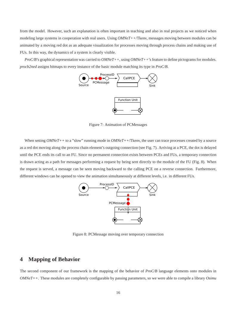
from the model. However, such an explanation is often important in teaching and also in real projects as we noticed when
modeling large systems in cooperation with real users. Using OMNeT++/Tkenv, messages moving between modules can be
animated by a moving red dot as an adequate visualization forprocesses moving through process chains and making use of
FUs. In this way, the dynamics of a system is clearly visible.
ProC/B’s graphical representation was carried toOMNeT++, usingOMNeT++’s feature to define pictograms for modules.
procb2nedassigns bitmaps to every instance of the basic module matching its type inProC/B.
Figure 7: Animation of PCMessages
When settingOMNeT++ to a ”slow” running mode inOMNeT++/Tkenv, the user can trace processes created by a source
as a red dot moving along the process chain element’s outgoing connection (see Fig. 7). Arriving at a PCE, the dot is delayed
until the PCE ends its call to an FU. Since no permanent connection exists between PCEs and FUs, a temporary connection
is drawn acting as a path for messages performing a request bybeing sent directly to the module of the FU (Fig. 8). When
the request is served, a message can be seen moving backward to the calling PCE on a reverse connection. Furthermore,
different windows can be opened to view the animation simultaneously at different levels, i.e. in different FUs.
Figure 8: PCMessage moving over temporary connection
4 Mapping of Behavior
The second component of our framework is the mapping of the behavior of ProC/B language elements onto modules in
OMNeT++. These modules are completely configurable by passing parameters, so we were able to compile a libraryOsimu
16

containing generic implementations for PCEs and standard FUs.
OMNeT++ offers two different programming styles, lightweight processes and a transaction based programming para-
digm. We decided to follow the latter as it matches the basic ideas of process chain models and it scales much better for
large models. Since process chains are characterized by theinterval of time consumed by a process between entering and
leaving a chain, a transaction based discrete event approach makes it natural to map these intervals to arrivals and departures
of messages to/from modules inOMNeT++.
The dynamic part ofProC/Bmodels are processes following the route defined by process chains. Analogously, processes
are represented by messages inOMNeT++. The mapping toOMNeT++ is done by subclassingcMessage only once to
PCMessage (short for ”process chain message”). Processes are marked with a unique identification number to trace their
movement inside the model for debugging and statistics. InProC/B, transitions of processes between PCEs are instantaneous,
time is consumed by requesting services at function units orby dedicated delay PCEs. This idea is reproduced inOMNeT++
by messages of typePCMessage that use connections in zero time, leaving progress of modeltime to the modules.
Implementation ofProC/B’s behavior is completely located in basicOMNeT++ modules, the leaves of the model tree.
Compound modules used inOMNeT++ to group simple modules to complex model elements are not allowed to define own
behavior in C++ code next to their*.ned-file. For this reason the behavior of higher level FUs had to be the union of semantics
defined by lower level PCEs, FUs and the way they are connectedwith each other. In syntactic terms we had to flatten the
model hierarchy to basicProC/Belements and connections.
This is an important difference to the former wayProC/Bwas implemented. Several functions regarding time progress,
message routing and measurement are located in every node ofthe model tree ofHIT. In the following we will describe our
solution for the implementation ofProC/B’s behavior withOMNeT++. Section 4.1 will also focus on an alternative to add
measurements to specific constructed FUs.
TheProC/B-mapping toOMNeT++ is conducted with an inheritance hierarchy. Each implementation of a basicProC/B
element inherits fromProCBElement. ProCBElement itself is a direct successor ofOMNeT++’s modeling interface
cSimpleModule. ProCBElement encapsulates several common functions forProC/Belements. On initialization, each
ancestor ofProCBElementwill register itself to the system. This allows faster location of ProC/Belements by name or by
their position in the model hierarchy. Sending process messages direct or via connection is also implemented at this place.
Keeping such basic functions at a high level in the inheritance hierarchy helps to keep a model wide consistent numbering
of input and output gates forOMNeT++ modules. An important group of functions is related to the centralized creation and
destruction of processes with unique identification numbers. The hierarchy tree splits into common base classes for each
general type ofProC/B-element. There are basic classes for sources, PCEs, FUs, sinks and connection elements. Figure 9
shows an extract of the inheritance hierarchy for all types of basic function units available inProC/B’s modeling library. The
base class for function units namedBaseFU provides consistent handling of arriving and leaving processes including updates
of statistic functions. For this reason, thehandleMessage()method required byOMNeT++ being implemented in every
module is forked into specialized handlers inside the base classes. PCEs must implementhandleProcessActivity()
and FUhandleProcessService() as shown later in Listings 3 and 4. Sources and sinks have similar constructs.
Assessing the way messages are handled in modules forProC/B elements also helps to realize timeouts for the activity
17

cSimpleModule
ProCBElement
BaseFU
CounterFU StorageFU
ExternalFU
ServerFU
FUMeasure
FCFSDiscipline PSDiscipline InfiniteDiscipline
<<interface>>
ServerDiscipline
BasePCE
BaseSource
PCConnector
others
Figure 9:ProC/B’s class hierarchy
duration of process chain elements. Each time a process chain element derived from typeBasePCE performs a service call
to a function unit, the process message is held back and replaced with a copy. The only difference between both messages is
a new unique ID for the copy. Both ID numbers are stored in an associative collection. The copy will be sent to the called
function unit while the original message still waits at the process chain element. When the service call is finished and the
copy returns, the original message is deleted and the ID is transferred to the copy rendering it as the original message from
now on. Recently we enhancedProC/Bby the option to set a timer before the copy is sent to the function unit (essentially
this timer option makes copying of processes necessary). Ifthe service call duration exceeds the time limit (i.e. the copy
does not arrive in time) the original message is released andsent to the next process chain element. The ID of the copy is
blacklisted and the copy is deleted when it arrives back later. Timeouts are a new feature realized in theProC/Bmapping to
OMNeT++ and are not supported by theHIT simulation environment. An extensive description including examples can be
found in [25].
Now we will describe two examples to explain our mapping of behavior more explicitly.
Figure 10 shows the symbol of a Delay PCE as a simple language element ofProC/B. It has the task to delay arriving
processes by some amount of time, either deterministic or bya random number from some predefined distribution. Listing 2
shows the corresponding*.ned-file used byOMNeT++ to pass parameters to modules and define gateways where messages
arrive and leave.
18

Figure 10:ProC/B’s symbol for a delaying PCE
Listing 2: Source of DelayPCE.ned
simple DelayPCE
parameters:
delay : string
gates:
in: in;
out: out;
endsimple
A process chain element DelayPCE is defined with just one pairof gates because it is connected to only two other process
chain elements. Parameterdelay is set by the*.ned-file instantiating this module as specified in the originalProC/Bmodel.
Implementations of DelayPCE subclassingcSimpleModule have to respect the fact that a second or third or an arbitrary
number of processes can arrive while the first process is still delayed. The concrete implementation in Listing 3 is short,
overloading the functionhandleProcessActivity (PCMessage* msg) and implementing the specific reaction on
arriving messages. The delay time is generated from the predefined distribution, the following line in the code delays the
incoming message by the amount of time usingOMNeT++’s sendDelayed() method. Please note that no messages are
stored inside the module, allowing the module to accept an infinite number of processes. Methodparam() reassembles the
well known methodpar() to fetch parameters stored in*.ned files. The new method parses expressions used inProC/B
models, which can be either arithmetic expressions or aProC/Bspecific naming of random distributions.
All elements ofProC/B’s process flow control had to be implemented as modules, too.As described before, process chain
connectors (Fig. 11) are used to synchronize processes. Their implementation asOMNeT++ module is shown in Listing 4.
Process messages arrive at the input gates of the module. They are stored immediately in queues, one queue for each input
gate. ProC/B allows us to specify a number of processes per gate that are required to start a transition which realizes the
synchronization. Such semantics similar to token consumption in Petri Nets can for example be used to model usage of goods
in production processes. The exact numbering is read from the process parameters of the arriving message in the first loop. If
Listing 3: Source of DelayPCE.cc
#include "DelayPCE.h"
void DelayPCE::handleProcessActivity(PCMessage* msg) {
double delay = (double) param("delay");
sendDelayed(msg, delay, "out");
}
19

Listing 4: Source of PCConnector.cc
void PCConnector:: handleProcess(cMessage *msg) {
PCMessage* message = (PCMessage*) msg;
int msgArrivalIndex = msg->arrivalGate()->index();
incomingQueues[msgArrivalIndex].insert(msg);
ProcessPar& p= message->getProcessPar();
for (int m=0; m<numberOfInputGates; m++) {
requiredProcessesPerGate[m] = p->requiredProcesses(name(), m);
}
if (! transitionEnabled()) return;
for (int gate=0; gate<numberOfInputGates; gate++) {
for (int m=0; m<requiredProcessesPerGate[gate]-1; m++) {
[...]
// consume enough messages for transition
delete incomingQueues[gate].pop();
}
// forward original message
PCMessage* lastOriginalMessage = (PCMessage*) incomingQueues[gate].pop();
[...]
send(lastOriginalMessage, "out", gate);
}
}
bool PCConnector::transitionEnabled() {
for (int i=0; i<numberOfOutputGates; i++) {
if (incomingQueues[i].length() < requiredProcessesPerGate[i]) return false;
}
return true;
}
20

Figure 11: PCConnector inProC/B for synchronization of three chains
a sufficient number of processes arrived (at least one per gate) the sentinel conditiontransitionEnabled() will allow
the transition to fire. Otherwise the transition has to wait for additional processes. After synchronization all processes will
arrive at the next element in their process chain at the same time.
Figure 12: Server Function Unit inProC/B
As an advanced example ServerFU is shown in Fig. 12. It represents a set of limited and identical resources which
processes can request and use. ServerFU offers the service ”request” to PCEs, a parameter for the requested amount of
service has to be passed with the calling message.
Listing 5: ServerFU.ned
simple ServerFU
parameters:
inPath: bool,
speed: numeric,
capacity: numeric,
discipline: string;
gates:
in: in;
out: out;
endsimple
Listing 5 contains the definition of ServerFUs inOMNeT++’s modeling language. Three parameters are passed to the
module byOMNeT++ at runtime:
speed of a resource to execute service calls. This means that calling PCEs request an amount of service according to some
average resource. The concrete FU can be faster (speed> 1), slower (speed< 1) or an average resource (speed= 1).
21

capacity number of resources offered by the server
discipline the resource scheduling the server uses.
By offering a single service, ServerFU only needs one pair ofgates. As stated before, messages are delivered to these gates
by direct send calls, making it unnecessary to connect this module with other elements in the model.
The parameter discipline plays an important role inProC/B models, as the behavior of function units are matched to
the way resources are shared in the real system. Currently three scheduling disciplines can be mapped fromProC/B to
OMNeT++:
FCFS queues serve requests for resources by the rule ”first come, first served”. Processes which obtained a resource, allocate
it according to the amount defined by the constant or distribution of the service call and parameterspeed.
IS ”Infinite Server”, every request is immediately granted andtakes the time specified by the service call and parameter
speed.
PS ”Processor Sharing”, all requests are immediately granted. Every process makes use of the full set of resources (accel-
erating service time by the number of resources), but has to share resources with other processes using the server at
the same time. Capacity is distributed uniformly among all processes (slowing down execution time by the reciprocal
value of the number of processes).
It is possible to interpret these three types of scheduling as different kinds of servers, yet their implementation inOM-
NeT++ uses only one module to simplify the structure mapping byprocb2ned. Internally ServerFU makes use of the strategy
pattern [26] to vary it’s behavior according to parameterdiscipline.
An excerpt of ServerFU’s source is shown in Listing 6. ThehandleMessage()method is divided into two parts by an
if clause, newly arriving process messages withselfMessage set to false are served in the lower part.
At the beginning,welcomeMessage computes some basic statistics of arriving processes as described in section 4 and
incrementsnumberMsgInSystem. Additionally, the ServerFU pushes its name inwriteNameInPath on the stack
keeping track of every process chain element the message passed through. The next line is part of the strategy pattern,
discipline holds objects of typeServerFU::Discipline encapsulating FCFS, Infinite Server or Processor Sharing
as described above. Those strategies are instantiated depending on parameterdiscipline in Listing 5 on the module’s
initialization. Their behavior on newly arriving processes is specified inhandleProcess(). Here we present the methods
FCFS and IS as examples: In FCFS, time is granted to processesas long as the servers capacity is not exceeded. Otherwise
the process is enqueued until resources become available. The Infinite Server is even more simple, it just accepts every
process.
In both examples, time consumption is modeled by schedulingprocess messages to the function unit itself, adding the
amount of time the service will take before sending. When themessage returns,selfMessage is true and the upper part
of handleMessage() is executed. Again, an object of typeServerFU::Discipline handles processes a second
time. In FCFS, the first process message waiting for free resources is removed from the queue and immediately scheduled
for completion of the service. For Infinite Server no furtheraction after service completion is necessary.
22

4.1 Translation of Result Measures
The main focus when analyzing a simulation model is on determining quantitative results for the model, like for example
throughputs or response times.ProC/B offers the possibility to measure properties at every FU, though depending on the
type of the FU the available properties may differ: Throughput, response time and population can be measured at any FU.
Additionally, for every server the utilization and for every storage the state can be examined. For composed FUs the modeler
may define further measures (called rewards inProC/B). ProC/Ballows for three different types of rewards:count, eventand
state. Rewards of the typeeventcan be used for serially collecting values, rewards of the typecountfor estimating rates and
rewards of the typestatefor the description of trajectories. Those types are used for the realization of standard measures
like throughput or response time as well. While the user-defined measures have to be updated manually (ProC/Bprovides a
model element for updating those rewards), the standard measures are updated automatically whenever a process enters or
leaves a FU.
As already mentionedProC/Ballows for streams to be itemized in detailed ways. This enables for example the measure-
ment of the train population at the terminal in Fig. 2 withoutcounting trucks. To achieve this, the modeler can specify a path
consisting of elements in theProC/Bmodel. Only processes, that have moved through all of the specified elements will be
considered when updating the stream. Most of the described features available inProC/Bare derived from the measures that
HIT offers, thus allowing an easy transformation fromProC/B to HIT.
Currently when analyzing the model withHIT, streams of data are generated during simulation, which arebasically lists of
pairs consisting of a time stamp and some associated value. This data is used to calculate the usual characteristics likemean,
standard deviation and confidence intervals for the different measures. TheProC/B toolset contains a tool, that generates
plots and visualizes the simulation results.
When usingOMNeT++ for simulation the key features like itemizing streams as well as the output data of the simulation
should be preserved, so that this new simulation environment fits into our existing toolset. WhileOMNeT++ offers basic
facilities for measurement in e.g. communication protocols, it needs to be extended to meet the demands for the simulation
of logistics networks.
In the remainder of this section it is shown how the measurement is implemented for Standard-FUs like servers or storages.
Measuring properties at composed FUs requires some additional effort and is presented afterwards. Finally the itemizing of
streams is explained.
For Standard-FUs the measurement streams have to be updatedwhen a process enters (which means a service of the FU
has been requested by a process) or leaves the FU. In theOMNeT++ representation of the model a service request is indicated
by a message sent to the FU. The population is updated whenever a process enters or leaves the FU, throughput and response
time are updated when a process leaves the FU. For Standard-FUs (like server or storage) the data collection and evaluation
is implemented as C++-Code within the corresponding simplemodules. This brings up problems for composed FUs: When
theProC/Bmodel is translated to anOMNeT++ representation, composed FUs are represented as compound modules, thus
only a *.neddescription exists that lacks the ability to implement codefor measurements. Therefore the module of every
composed FU contains a specific simple module calledFUMeasures (see Fig. 13) to realize measurements in composed
23

FUs.
Figure 13: Message flow for the measurement in composed FUs
Fig. 13 shows the message flow that is necessary for measurements in composed FUs. Starting at the source a message is
sent to the Process-ID (Process-IDs are used for the identification of a process chain and the declaration of local variables and
are always connected with the source of a process chain). From there a message is sent to the special moduleFUMeasures.
This module has no counterpart inProC/B and its sole purpose is to enable the measurement in composedFUs. After the
message is returned to the Process-ID, further elements of the process chain are processed (denoted by three dots in Fig.13).
When the process has reached the sink, the message is sent to the moduleFUMeasures and back to the sink again. All
update operations of streams for a FU are performed withinFUMeasures. The first message (sent by the Process-ID) means
that a process has entered the FU (and thus the population is updated for example), the second message (sent by the sink)
means that a process is leaving the FU again. AlthoughFUMeasures is not an element of theProC/B language it is part
of the inheritance hierarchy of function units (cf. Fig. 9) in theOsimulibrary. The superclassBaseFU adds the ability to
return incoming process messages to the sending Process-IDor sink. Similar to calls of other FUs a stack of senders inside
PCMessage is used to find the originator.
As already mentioned,ProC/Ballows one to specify a path consisting of elements, so that only processes, that moved along
that path through the model will be considered when updatingmeasures. Those paths are part of theProC/B experiment
description and need to be translated to theOMNeT++ model and taken into account during the update of measurement
streams. When mapping toOMNeT++ the ProC/B experiment description is saved in an*.ini -file, that is loaded when
the simulation starts. Additionally, a parameter is set foreach element appearing in one of the paths in the corresponding
*.ned-file when the model structure is mapped. During simulation the path a message takes through the model is saved and
compared with the paths that have been specified in theProC/Bexperiment. To store this information a new message class
is used, that can carry the path information. Updates of the measurement streams are only performed when the path of the
message matches one of those paths from theProC/Bexperiment.
OMNeT++ provides several classes for the collection of data and the generation of statistical measures like mean or
standard deviation which are derived from the abstract classCStatistic. Because the calculation of means does not match
the specification of the streams inProC/B, ourProC/B to OMNeT++ implementation provides its own classes (derived from
CStatistic) to generate statistics (one for each of the stream typesevent, stateandcountmentioned before). For the
24

estimation of confidence intervals the batch means-method [27] is used. The generated output is saved in the same format as
the output ofHIT, so that our existing tools can parse the data for result presentation.
5 Validation of the Transformation
If different tools are used to simulate a model, then it is necessary that the semantics of the model is the same in every
simulation tool. Ideally, identity of semantics should be proved formally. A formal proof would require a formal semantics
such that formal analysis techniques are applicable to check equivalence. Unfortunately, simulation models are much too
complex to be described in simple languages that allow a formal analysis. This implies that identical behavior of models
cannot be strictly verified, it can only be validated.
ProC/Bwas designed to introduce a well defined semantics and an automated analysis to hierarchical process chain mod-
els. A specification was laid down in [23], describing the semantics of PCEs and FUs in an operational form. Many aspects
of the operational semantics are implicitly defined by the HIT runtime environment. Thus, the behavior of the HIT simulation
model is the behavior which should be observed whenOMNeT++ executes the model. However, the operational semantics
depends on several aspects like execution order of simultaneous events, the order of initialization which are generally not
well defined in discrete event simulation and, additionally, the realization of random processes that depend on the random
number generator.
We distinguish between validation of models with and without random numbers. The former will be named deterministic
models, although this is not strictly correct since simultaneous events may yield a non deterministic behavior. For deter-
ministic models behavior can be compared using traces. Although,HIT andOMNeT++ both have a trace function it is not
recommended to use these functions for comparisons since the format differs and cannot be easily transformed from one to
another. Instead models are augmented with code PCEs including output statements. Such PCEs can be added to every PC.
Thus,HIT andOMNeT++ generate the same trace output which can be easily compared.
To prove equality of traces we developed an automated testing environment to compare output ofProC/Bmodels analyzed
with HIT andOMNeT++. It is based on a set of simple and deterministicProC/Bmodels, designed to test the behavior of
exactly one element ofProC/B’s language. Driven by our batch testing environment, identically formatted output ofHIT and
OMNeT++ is compared by an awk script, highlighting differences in measurement results and event traces. Additionally,
a selection of deterministic models taken from former projects is also subject to comparison, making sure that ourProC/B
language elements implemented in modules interact correctly.
Testing nondeterministic models is limited since different random number generators are used inHIT (actually implemen-
tations of SIMULA) andOMNeT++. So, even starting with same seeds, results and event orderswill differ. Consequently,
we can only check in a statistical sense whether the implementation is correct, i.e., the different language elements behave
identically. For this purpose, animations can be compared,traces can be visualized and results can be compared using statisti-
cal test. A typical approach is to estimate the same measure with both simulators,HIT andOMNeT++, and then statistically
evaluate a random variable describing the difference between both measures. This can be done by comparing confidence
intervals or using statistical tests (for details see e.g. [24][chap. 10]).
25

Table 1 shows simulation results of an M/M/1 system (ρ = 0.5) as an example of a simple nondeterministic system included
in our testing environment. Results are sufficiently close to assume an equivalent behavior for this model with a high signif-
icance probability. The second example are values taken from a central server system [28], also a nondeterministic system.
Comparisons of simulation results in table 2 also indicate equivalence. A detailed analysis of the central server system with
ProC/B is available in [29].
We additionally compared several simulation results of larger models and obtained similar minor differences (cf. Sect. 6).
Table 1: M/M/1 system simulation results (90% confidence interval)
Population Throughput Response time
HIT 1.00202 1.00023 1.001789
±0.18% ±0.05% ±0.16%
OMNeT++ 1.00126 0.99964 1.000905
±0.33% ±0.14% ±0.22%
Table 2: Comparison of simulation results for Central Server (90% confidence interval)
Population Throughput Response time
HIT 1.1559 0.7491 1.5429
±0.16% ±0.15% ±0.23%
OMNeT++ 1.1548 0.7499 1.5398
±0.15% ±0.15% ±0.23%
6 Comparison of performance and simulation results
Though our implementation ofProC/Bon OMNeT++ is not as mature as the one onHIT, we achieved promising runtime
results. Times in table 3 were taken for analyzing a model over 1.000.000 time units omitting model initialization and output.
Table 3: Runtime comparison
Model HIT OMNeT++
M/M/1 0 min. 57 sec. 0 min. 22 sec.
Central Server 0 min. 35 sec. 0 min. 24 sec.
Freight Village 8 min. 36 sec. 2 min. 33 sec.
26

Our examples indicate thatOMNeT++ is in most cases about 2 to 3 times faster thanHIT.
The runtime comparison in table 3 features the M/M/1 system mentioned before as well as the execution time of the freight
village model introduced in Sect. 2.1. The measurements forthe central server system show an improvement in runtime of
only approx. 30% forOMNeT++. Since the model is based on a closed loop with only two activeprocesses, less CPU time
for process incarnations and queuing is used such that the difference between the two tools shrinks [29]. Still, a significant
speed up can be noticed.
The values given forOMNeT++are preliminary as we focussed on correct mapping of behavior and ignored performance
issues for the time being. Performance bottlenecks still exist in statistical methods and dynamic search of matching function
units to PCEs.
Table 4 shows some simulation results for the model of the freight village from Sect. 2.1. The table contains population,
throughput and response time for the FUforklifts (see Figs. 2 and 3) estimated withHIT andOMNeT++. As one can
see the results are similar.
Table 4: Comparison of simulation results for the server forklifts (95% confidence interval)
Population Throughput Response time
HIT 4.988794 0.366475 13.612308
±0.30521% ±0.312747% ±0.633167%
OMNeT++ 5.02047 0.36527 13.744485
±0.752181% ±0.353753% ±0.895352%
7 Conclusions
OMNeT++ is an environment which has been mainly designed for the simulation of communication networks. In this paper
we demonstrated how to enableOMNeT++ for being used in other areas. We described the automated transformation of
hierarchical process chains specified byProC/Bmodels to corresponding hierarchicalOMNeT++ models.
Since the world views ofProC/BandOMNeT++ differ, the transformation is not straightforward and has to respect several
special features ofProC/B. For example: Elements of the behavior description, like process chain elements (PCEs), are
mapped to nodes, i.e. structural components, in theOMNeT++ description in order to exploitOMNeT++’s animation
capabilities. Furthermore additional elements for measurements are created asOMNeT++ elements which do not have a
direct correspondence in the originalProC/Bmodel.
The “correctness” of the transformation has been validatedby several test models where we inserted special output com-
mands, so that discrepancies from the execution viaOMNeT++ and the reference simulatorHIT can be detected automati-
cally.
The current implementation is a prototype and future work will concentrate on further improvements of the simulation
27

efficiency and the connection to existingProC/B tools andOMNeT++ modeling features. One of the next steps will be the
utilization of Akaroa parallel simulation libraries to reduce runtimes by using multiple computers in parallel. Furthermore
we are continuing recent work [25] using theOMNeT++ framework INET for the combination of high-level service-oriented
architecture (SOA) components and detailed lower level network architecture and protocols. In this approach SOA compo-
nents and their orchestration are described inProC/B, and the network architecture is specified inOMNeT++. By means of
the automated transformation ofProC/Bmodels toOMNeT++ described in this paper, both models can be combined into a
single executable simulation model of the overall system.
References
[1] D. W. Schunk and B. M. Plott. Using Simulation to Analyze Supply Chains. InProceedings of the 32nd WinterSimulation Conference, pages 1095–1100, 2000.
[2] M. D. Rossetti and H.-T. Chan. A Prototype Object-Oriented Supply Chain Simulation Framework. In Chick et al. [30],pages 1612–1620.
[3] ARIS business simulator, 2007. URL:http://www.ids-scheer.de/.
[4] J. Rathmell and D. T. Sturrock. The Arena Product Family:Enterprise Modeling Solutions. In Snowdon and Charnes[31], pages 165–172.
[5] M. W. Rohrer and I. McGregor. Simulating Reality Using AutoMod. In Snowdon and Charnes [31], pages 173–181.
[6] F. Bause, H. Beilner, M. Fischer, P. Kemper, and M. Volker. The ProC/B Toolset for the Modelling and Analysis ofProcess Chains. In T. Field, P. G. Harrison, J. T. Bradley, and U. Harder, editors,Computer Performance Evaluation /TOOLS, volume 2324 ofLecture Notes in Computer Science, pages 51–70. Springer, 2002.
[7] H. Beilner, J. Mater, and N. Weißenberg. Towards a performance modelling environment: News on HIT. In R. Puigjanerand D. Potier, editors,Modeling techniques and tools for computer performance evaluation, pages 57–75, 1989.
[8] P. Buchholz, D. Muller, P. Kemper, and A. Thummler. OPEDo: A Tool Framework for Modeling and Optimizationof Stochastic Models. In L. Lenzini and R. L. Cruz, editors,Proceedings of the 1st International Conference onPerformance Evaluation Methodologies and Tools, VALUETOOLS 2006, page 61. ACM, 2006.
[9] P. Kemper and C. Tepper. Traviando - Debugging Simulation Traces with Message Sequence Charts. InInternationalConference on Quantitative Evaluation of SysTems (QEST), pages 135–136. IEEE Computer Society, 2006.
[10] F. Bause, P. Buchholz, J. Kriege, and S. Vastag. Simulating Process Chain Models with OMNeT++. InProc. of the FirstInternational Conference on Simulation Tools and Techniques for Communications, Networks and Systems (SIMUTools2008), Marseille (France), March 2008.
[11] Omnet++ community side. URL:http//www.omnetpp.org/.
[12] J. Huang. Simulative Bewertung von ProC/B-Modellen. Master’s thesis, Universitat Dortmund, Fachbereich Informatik,Lehrstuhl 4, Dortmund, 2006.
[13] Q. Zhu. Beschreibung von ProC/B-Modellen zur simulativen Bewertung. Master’s thesis, Universitat Dortmund,Fachbereich Informatik, Lehrstuhl 4, Dortmund, 2006.
[14] Collaborative Research Center 559 “Modelling of LargeLogistics Networks”. http://www.sfb559.uni-dortmund.de.
[15] P. Buchholz and U. Clausen.Große Netze der Logistik - Die Ergebnisse des Sonderforschungsbereichs 559. Springer,2009.
[16] M. B. Juric. Business Process Execution Language for Web Services. Packt Publishing Limited, 2006.
28
[17] M. Arns and T. Hartel. BPEL fur Prozessketten. In P. Buchholz, editor,Workshop ”Modellierung großer Netze in derLogistik”, Dortmund, Research Report 819/2008, Computer Science, TU Dortmund, 2008.
[18] Osman Balci. Verification, Validation, and Certification of Modeling and Simulation Applications. In Chick et al. [30],pages 150–158.
[19] T. Murata. Petri Nets: Properties, Analysis and Applications.Proc. of the IEEE, 77:541–580, 1989.
[20] F. Bause and J. Kriege. Detecting Non-Ergodic Simulation Models of Logistics Networks. InProc. of the SecondInternational Conference on Performance Evaluation Methodologies and Tools (VALUETOOLS 2007), October 2007.
[21] P. Buchholz and C. Tepper. Functional Analysis of Process Oriented Systems. In H. Fleuren, D. den Hertog, and P. Kort,editors,Operations Research Proceedings, pages 127–135. Springer, 2005.
[22] H. Beilner, J. Mater, and C. Wysocki. The HierarchicalEvaluation Tool HIT. InShort Papers and Tool Descriptions ofthe 7th International Conference on Modelling Techniques and Tools for Computer Performance Evaluation, 1994.
[23] F. Bause, H. Beilner, and M. Schwenke. Semantik des ProC/B-Paradigmas. Technical Report 03001, ISSN 1612-1376,Sonderforschungsbereich 559 “Modellierung großer Netze in der Logistik”, 2003.
[24] W. D. Kelton and A. Law.Simulation Modeling and Analysis. McGraw Hill, 2000.
[25] F. Bause, P. Buchholz, J. Kriege, and S. Vastag. A Framework for Simulation Models of Service-Oriented Architectures.In S. Kounev, I. Gorton, and K. Sachs, editors,SPEC International Performance Evaluation Workshop 2008 (SIPEW2008), pages 208–227. LNCS 5119, Springer, June 2008.
[26] E. Gamma, R. Helm, R. Johnson, and J. Vlissides.Design Patterns. Elements of Reusable Object-Oriented Software.Addison-Wesley, 1995.
[27] G.S. Fishman.Discrete-Event Simulation Modeling, Programming and Analysis. Springer, 2001.
[28] S. Lavenberg.Computer Performance Modeling Handbook. Academic Press, 1983.
[29] Jan Kriege and Sebastian Vastag. ProC/B goes OMNeT++: Efficient Simulation of Process Chains. In Falko Bause andPeter Buchholz, editors,Proc. of the 14th GI/ITG Conference on Measurement, Modeling, and Evaluation of Computerand Communication Systems (MMB 2008), pages 303–305, Dortmund, 2008. VDE Verlag.
[30] S. E. Chick, P. J. Sanchez, D. M. Ferrin, and D. J. Morrice, editors.Proceedings of the 35th Winter Simulation Confer-ence: Driving Innovation, New Orleans, Louisiana, USA, December 7-10, 2003. ACM, 2003.
[31] J. L. Snowdon and J. M. Charnes, editors.Proceedings of the 34th Winter Simulation Conference: Exploring NewFrontiers, San Diego, California, USA, December 8-11, 2002. ACM, 2002.
29

Listing 6: Excerpt from ServerFU.cc
void ServerFU::handleProcessService(cMessage* msg) {
PCMessage* message = (PCMessage*) msg;
if (message->isSelfMessage()) {
// message was scheduled by handleProcess()
discipline->handleSelfMessage(message);
finishService(message);
dismissMessage(message);
return;
}
welcomeMessage(message);
writeNameInPath(message);
discipline->handleProcess(message);
}
void ServerFU::FCFSDiscipline::handleProcess(PCMessage* message) {
if (parent->numberMsgInSystem <= parent->serverCapacity) {
parent->scheduleAt(simulation.simTime() + serviceTime(message), message);
}
else fcfsQueue.insert(message);
}
void ServerFU::FCFSDiscipline::handleSelfMessage(PCMessage* message) {
if (fcfsQueue.empty()) return;
PCMessage* msgFromQueue = (PKMessage*) fcfsQueue.pop();
parent->scheduleAt(simulation.simTime() + serviceTime(msgFromQueue), msgFromQueue);
}
double ServerFU::FCFSDiscipline::serviceTime(PKMessage* message) {
return parent->getTaskTime(message) / parent->stdSpeed;
}
void ServerFU::ISDiscipline::handleProcess(PCMessage* message) {
parent->scheduleAt(simulation.simTime() + serviceTime(message), message);
}
[...]
void ServerFU::PSDiscipline::handleProcess(PCMessage* message) {
// implementation of processor sharing discipline
}
30