a strategy for attacking excess water production …
TRANSCRIPT
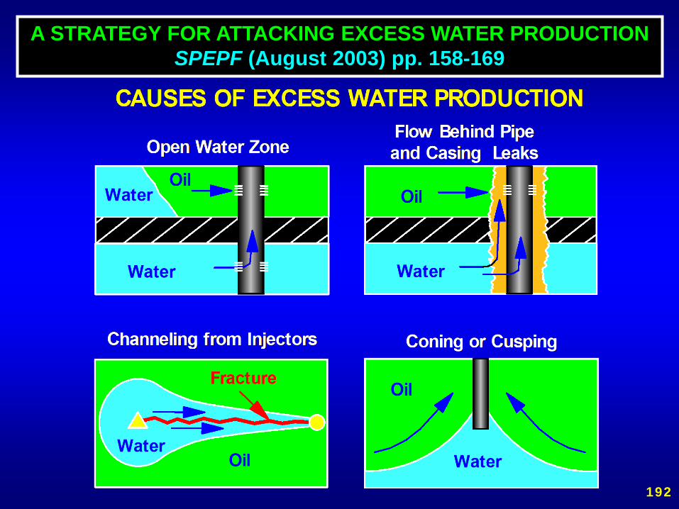
A STRATEGY FOR ATTACKING EXCESS WATER PRODUCTIONSPEPF (August 2003) pp. 158-169
192

•Cement, sand plugs, calcium carbonate.•Packers, bridge plugs, mechanical patches.•Pattern flow control.• In fill drilling/well abandonment.•Horizontal wells.•Gels.•Polymer floods.•Resins.•Foams, emulsions, particulates, precipitates,
microorganisms.
WATER CONTROL METHODS
193

PROBLEMOperators often do not adequately diagnosethe cause of their water production problems.
WHY NOT?1. Diagnosis requires money and time,2. Uncertainty about which methods are cost-
effective for diagnosing specific problems,3. Preconception that only one type of problem
exists or that one method will solve all typesof problems,
4. Some companies encourage a belief thatthey have "magic-bullet" solutions.
194

A STRATEGY FOR ATTACKINGEXCESS WATER PRODUCTION
1. Consider and eliminate the easiest problems first.
2. Start by using information that you already have.
195

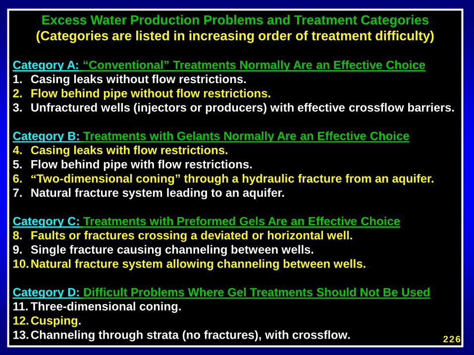
Excess Water Production Problems and Treatment Categories(Categories are listed in increasing order of treatment difficulty)
Category A: “Conventional” Treatments Normally Are an Effective Choice1. Casing leaks without flow restrictions.2. Flow behind pipe without flow restrictions. 3. Unfractured wells (injectors or producers) with effective crossflow barriers.
Category B: Treatments with Gelants Normally Are an Effective Choice4. Casing leaks with flow restrictions.5. Flow behind pipe with flow restrictions.6. “Two-dimensional coning” through a hydraulic fracture from an aquifer.7. Natural fracture system leading to an aquifer.
Category C: Treatments with Preformed Gels Are an Effective Choice8. Faults or fractures crossing a deviated or horizontal well.9. Single fracture causing channeling between wells.10.Natural fracture system allowing channeling between wells.
Category D: Difficult Problems Where Gel Treatments Should Not Be Used11. Three-dimensional coning.12.Cusping.13.Channeling through strata (no fractures), with crossflow. 196

WHAT DIAGNOSTIC TOOLS SHOULD BE USED?1. Production history, WOR values, GOR values 2. Pattern recovery factors, zonal recovery factors3. Pattern throughput values (bubble maps)4. Injection profiles, production profiles5. Zonal saturation determinations (from logs, cores, etc.)6. Injectivities, productivites (rate/pressure), step rate tests7. Casing/tubing integrity tests (leak tests)8. Temperature surveys, noise logs9. Cement bond logs 10.Televiewers, FMI logs11. Interwell transit times, water/hydrocarbon composition12.Mud losses & bit drops while drilling13.Workover & stimulation responses, previous treatments14.Pressure transient analysis, Inter-zone pressure tests15.Geological analysis, seismic methods, tilt meters16.Simulation, numerical, analytical methods17.Other 197
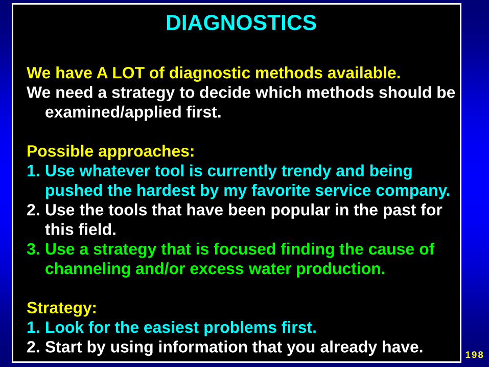
DIAGNOSTICS
We have A LOT of diagnostic methods available.We need a strategy to decide which methods should be
examined/applied first.
Possible approaches:1. Use whatever tool is currently trendy and being
pushed the hardest by my favorite service company.2. Use the tools that have been popular in the past for
this field.3. Use a strategy that is focused finding the cause of
channeling and/or excess water production.
Strategy:1. Look for the easiest problems first.2. Start by using information that you already have. 198

KEY QUESTIONS IN OUR APPROACH
1. Does a problem really exist?2. Does the problem occur right at the wellbore (like
casing leaks or flow behind pipe) or does it occur out beyond the wellbore?
3. If the problem occurs out beyond the wellbore, are fractures or fracture-like features the main cause of the problem?
4. If the problem occurs out beyond the wellbore and fractures are not the cause of the problem, can crossflow occur between the dominant water zones and the dominant hydrocarbon zones?
Respect basic physical and engineering principles.Stay away from black magic.
199

DOES A PROBLEM REALLY EXIST?
• Are significant volumes of mobile hydrocarbon present?
• Are recovery factors and/or WOR values much greater than neighboring wells or patterns?
• Are recovery values much less than expected after considering existing drive mechanism, existing stratification, structural position of the wells, injection fluid throughput, and existing mobility ratio?
200
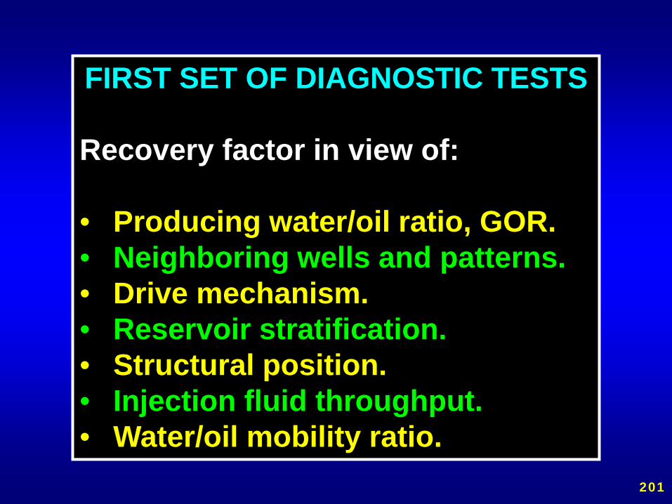
FIRST SET OF DIAGNOSTIC TESTS
Recovery factor in view of:
• Producing water/oil ratio, GOR.• Neighboring wells and patterns.• Drive mechanism.• Reservoir stratification.• Structural position.• Injection fluid throughput.• Water/oil mobility ratio.
201
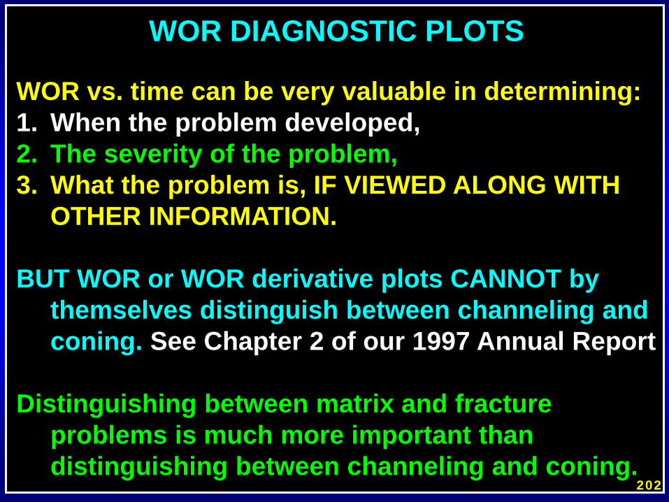
WOR DIAGNOSTIC PLOTS
WOR vs. time can be very valuable in determining:1. When the problem developed,2. The severity of the problem,3. What the problem is, IF VIEWED ALONG WITH
OTHER INFORMATION.
BUT WOR or WOR derivative plots CANNOT by themselves distinguish between channeling and coning. See Chapter 2 of our 1997 Annual Report
Distinguishing between matrix and fracture problems is much more important than distinguishing between channeling and coning.
202

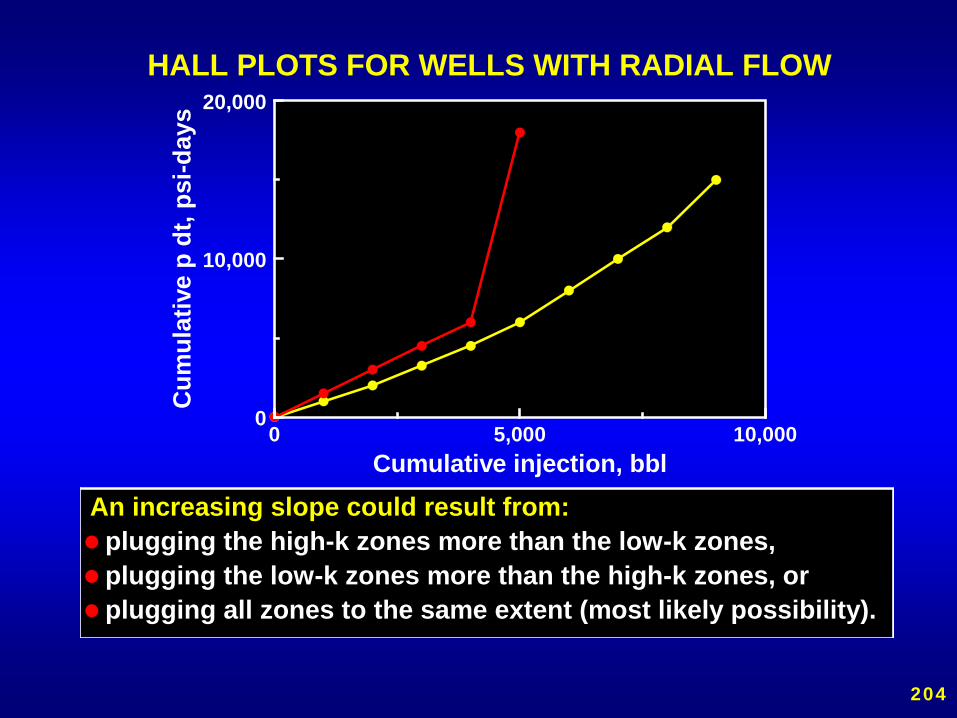
HALL PLOTS• provide a useful indication of the rate
of pressure increase,• indicate when gelant injection must
be stopped because of pressure limitations,
• do not indicate the selectivity of gel placement,
• do not indicate whether a treatment was sized properly.
Reference: DOE/BC/14880-5, pp. 73-80.
203
0 5,000 10,0000
10,000
20,000
Cumulative injection, bbl
Cum
ulat
ive
p dt
, psi
-day
s
HALL PLOTS FOR WELLS WITH RADIAL FLOW
An increasing slope could result from:plugging the high-k zones more than the low-k zones,plugging the low-k zones more than the high-k zones, orplugging all zones to the same extent (most likely possibility).
204

HALL PLOTS FOR FRACTURED WELLS
A decreasing slope could result from:opening or fracturing into previously unswept zones,re-opening a fracture that the gel had recently sealed,opening a fracture that cuts through all zones.
0 5,000 10,0000
5,000
10,000
Cumulative injection, bbl
Cum
ulat
ive
(p d
t), p
si-d
ays
205

CATEGORY A: EASIEST PROBLEMS“Conventional” Treatments Normally Are an Effective Choice
1. Casing leaks without flow restrictions (moderate to large holes).
2. Flow behind pipe without flow restrictions (typically no primary cement).
3. Unfractured wells (injectors or producers) with effective barriers to crossflow.
206
Does the problem occur right at the wellbore?Is the problem a leak or flow behind pipe?
•Leak tests/casing integrity tests•Temperature surveys•Radio-tracer flow logs•Spinner surveys•Cement bond logs •Borehole televiewers•Noise logs
SECOND SET OF DIAGNOSTIC TESTS
207
CATEGORY B:INTERMEDIATE DIFFICULTYTreatments with GELANTS
Normally Are an Effective Choice
4. Casing leaks with flow restrictions (pinhole leaks).
5. Flow behind pipe with flow restrictions(narrow channels).
6. “Two-dimensional coning” through ahydraulic fracture from an aquifer.
7. Natural fracture system leading to an aquifer.
208

Oil Oil
Water WaterFracture faces
Frac
ture
Gel
Gel
Problem 6: “Two-dimensional coning” through a hydraulic fracture from an aquifer.
•Need a gel that reduces kw much more than ko or kgas.
209

Problem 7:Natural fracture system leading to an aquifer.
•Many successful gelant treatments applied in dolomite formations.•Treatment effects were usually temporary.•Recent, longer lasting successes seen with preformed gels.
210

CATEGORY C:INTERMEDIATE DIFFICULTY
Treatments with PREFORMED GELSAre an Effective Choice
8. Faults or fractures crossing a deviated or horizontal well.
9. Single fracture causing channeling between wells.
10. Natural fracture system allowing channeling between wells.
211

water
oil
fracture or faulthorizontal well
FRACTURES OR FAULTS OFTEN ALLOW UNCONTROLLED WATER
ENTRY INTO HORIZONTAL OR DEVIATED WELLS.
Problem 8
212
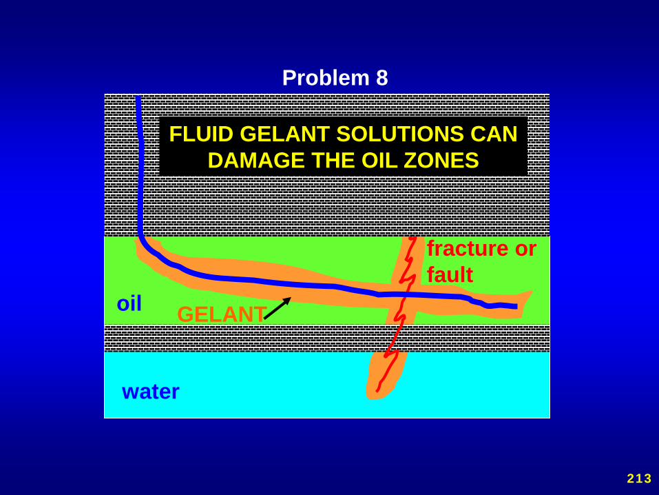
water
oil
fracture or fault
GELANT
FLUID GELANT SOLUTIONS CAN DAMAGE THE OIL ZONES
Problem 8
213

water
oil
horizontal well and fracture filled with gel
FORMED GELS WON’T ENTER POROUS ROCK. INSTEAD THEY EXTRUDE INTO THE FRACTURE
(gel can be washed out of well later)
Problem 8: SPE 65527
214
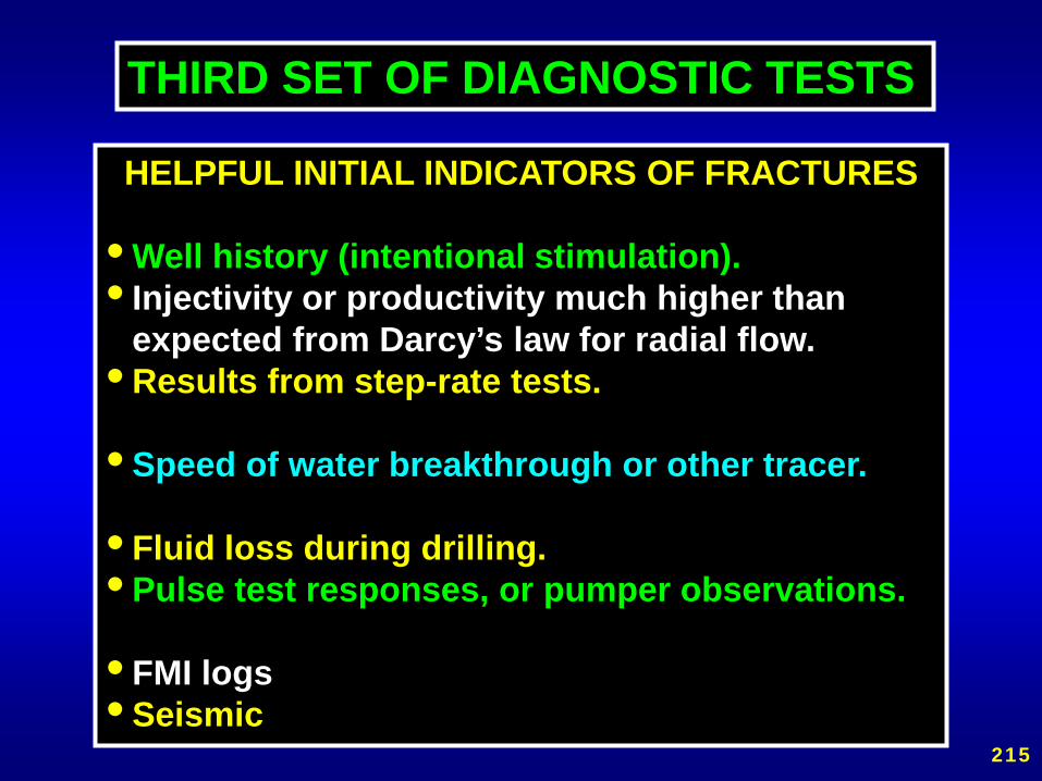
HELPFUL INITIAL INDICATORS OF FRACTURES
• Well history (intentional stimulation).• Injectivity or productivity much higher than
expected from Darcy’s law for radial flow.• Results from step-rate tests.
• Speed of water breakthrough or other tracer.
• Fluid loss during drilling.• Pulse test responses, or pumper observations.
• FMI logs• Seismic
THIRD SET OF DIAGNOSTIC TESTS
215

Does my well have a linear-flow problem?(e.g., a fracture)
Injectivity or productivity data oftenprovides a low-cost method for diagnosis.
Radial (matrix) flow probable:q/∆p ≤ (Σ k h)/[141.2 µ ln (re / rw)]
Linear (fracture-like) flow probable:q/∆p >> (Σ k h)/[141.2 µ ln (re / rw)]
216
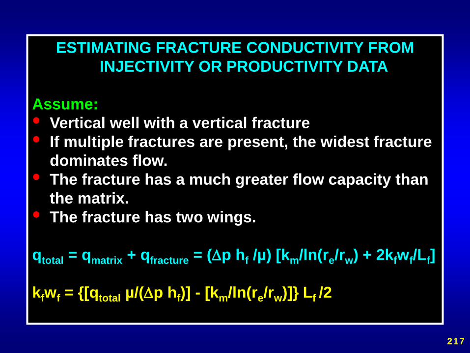
ESTIMATING FRACTURE CONDUCTIVITY FROM INJECTIVITY OR PRODUCTIVITY DATA
Assume:• Vertical well with a vertical fracture• If multiple fractures are present, the widest fracture
dominates flow.• The fracture has a much greater flow capacity than
the matrix.• The fracture has two wings.
qtotal = qmatrix + qfracture = (∆p hf /µ) [km/ln(re/rw) + 2kfwf/Lf]
kfwf = {[qtotal µ/(∆p hf)] - [km/ln(re/rw)]} Lf /2
217
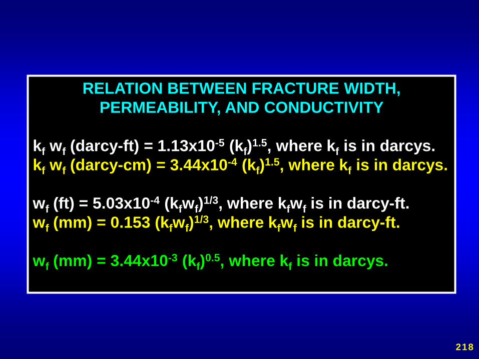
RELATION BETWEEN FRACTURE WIDTH, PERMEABILITY, AND CONDUCTIVITY
kf wf (darcy-ft) = 1.13x10⁻⁵ (kf)1.5, where kf is in darcys.kf wf (darcy-cm) = 3.44x10⁻⁴ (kf)1.5, where kf is in darcys.
wf (ft) = 5.03x10⁻⁴ (kfwf)1/3, where kfwf is in darcy-ft.wf (mm) = 0.153 (kfwf)1/3, where kfwf is in darcy-ft.
wf (mm) = 3.44x10⁻³ (kf)0.5, where kf is in darcys.
218

0.0001
0.001
0.01
0.1
1
10
100
1000
10000
100000
1000000
0.01 0.1 1 10Fracture width, mm
Frac
ture
con
duct
ivity
, dar
cy-ft
1
10
100
1000
10000
100000
1000000
10000000
Frac
ture
per
mea
bilit
y, d
arcy
s
THE WIDEST FRACTURE DOMINATES FLOW
219

0.1
1
10
100
1000
0.1 1 10 100 1000Interwell tracer transit time, days
Effe
ctiv
e pe
rmea
bilit
y of
the
flow
pat
h,
darc
ys
.
MATRIX OR FRACTURE FLOW?
µ=1 cp, ∆p=2000 psi, re=1000 ft.L~2re, which depends on well spacing
Matrix flowprobable
Fracture flowprobable
k ~ µ re2 /(4t ∆p)
220

ESTIMATING FRACTURE PERMEABILITY FROM TRACER TRANSIT TIMES
Assume the widest fracture dominates flow.
kf = qµL/[hfwf ∆p] = (Lhfwf/t)µL/[hfwf ∆p] = (L2 µ) /(∆p t)
Where: L is fracture length (~distance between wells),µ is fluid viscosity (usually of water),∆p is the pressure drop between wells,t is tracer transit time between wells.
221

CATEGORY D:MOST DIFFICULT PROBLEMS
GELANT or GEL Treatments Should NOT Be Used
11. Three-Dimensional Coning
13. Channeling through strata (no fractures),with crossflow.
12. Cusping
222
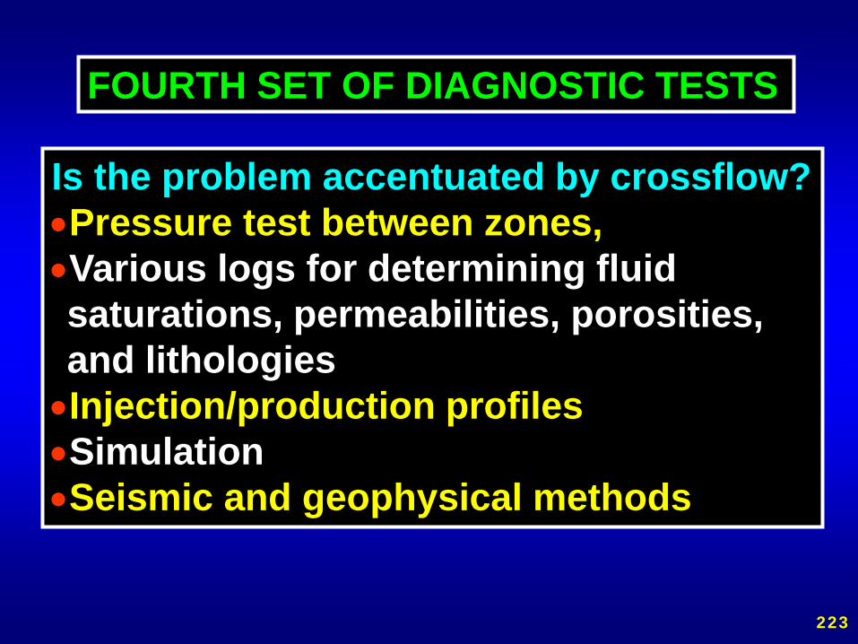
Is the problem accentuated by crossflow?•Pressure test between zones,•Various logs for determining fluid saturations, permeabilities, porosities, and lithologies
•Injection/production profiles•Simulation•Seismic and geophysical methods
FOURTH SET OF DIAGNOSTIC TESTS
223

PREDICTING EXCESS WATER PRODUCTIONFACTORS LEADING TO PROBLEMS
1. Bad cement or factors inhibiting cementation.2. Corrosive brines or gases. 3. Wellbore abuse during work-overs or well
interventions.4. Natural fractures (if oriented wrong).5. Large permeability contrasts.6. Low permeability rock (if induced fractures are
oriented wrong).7. Viscous oils or unfavorable mobility ratios.8. Close proximity of an aquifer or gas cap.9. Crossflow, under the wrong conditions (Items 5, 6,
and 7 above).10. Particulates or emulsions in injection water.
224

A STRATEGY FOR ATTACKINGEXCESS WATER PRODUCTION
1. Consider and eliminate the easiest problems first.
2. Start by using information that you already have.
225
Excess Water Production Problems and Treatment Categories(Categories are listed in increasing order of treatment difficulty)
Category A: “Conventional” Treatments Normally Are an Effective Choice1. Casing leaks without flow restrictions.2. Flow behind pipe without flow restrictions. 3. Unfractured wells (injectors or producers) with effective crossflow barriers.
Category B: Treatments with Gelants Normally Are an Effective Choice4. Casing leaks with flow restrictions.5. Flow behind pipe with flow restrictions.6. “Two-dimensional coning” through a hydraulic fracture from an aquifer.7. Natural fracture system leading to an aquifer.
Category C: Treatments with Preformed Gels Are an Effective Choice8. Faults or fractures crossing a deviated or horizontal well.9. Single fracture causing channeling between wells.10.Natural fracture system allowing channeling between wells.
Category D: Difficult Problems Where Gel Treatments Should Not Be Used11. Three-dimensional coning.12.Cusping.13.Channeling through strata (no fractures), with crossflow. 226

KEY QUESTIONS IN OUR APPROACH
1. Does a problem really exist?2. Does the problem occur right at the wellbore (like
casing leaks or flow behind pipe) or does it occur out beyond the wellbore?
3. If the problem occurs out beyond the wellbore, are fractures or fracture-like features the main cause of the problem?
4. If the problem occurs out beyond the wellbore and fractures are not the cause of the problem, can crossflow occur between the dominant water zones and the dominant hydrocarbon zones?
Respect basic physical and engineering principles.Stay away from black magic.
227