a study on the effects of ball defects on the fatigue life
TRANSCRIPT

A Study on the Effects of Ball Defects on the Fatigue Life in Hybrid Bearings
Ching-Yao (Tony) Tang*, Chad E. Foerster*, Michael J. O’Brien*, Brian S. Hardy*, Vinay K. Goyal*, Benjamin A. Nelson*, Ernest Y. Robinson**, Peter C. Ward* and Michael R. Hilton*
Abstract
Hybrid ball bearings using silicon nitride ceramic balls with steel rings are increasingly being used in space mechanism applications due to their high wear resistance and long rolling contact fatigue life.However, qualitative and quantitative reports of the effects of ball defects that cause early fatigue failure are rare. We report on our approach to study these effects. Our strategy includes characterization of defects encountered in use, generation of similar defects in a laboratory setting, execution of full-scale bearing tests to obtain lifetimes, post-test characterization, and related finite-element modeling to understand the stress concentration of these defects. We have confirmed that at least one type of defect of appropriate size can significantly reduce fatigue life. Our method can be used to evaluate other defects as they occur or are encountered.
Introduction
Recently, silicon nitride (Si3N4) ceramic balls have become an important component of advanced bearings used in a wide range of applications. The greatest commercial success for Si3N4 balls have been in hybrid bearings, which combine the ceramic balls with steel races. Compared to the steel ballsthat they replace, the ceramic balls are harder and less dense and offer many other advantages, such as higher compressive strength, better corrosion resistance, and reduced susceptibility to lack of lubricant or lubricant breakdown. These benefits make the hybrid bearings ideal for severe high-speed applications.
However, during the development of hybrid bearings for space mechanism applications, we became aware of ball flaws, particularly scars, scratches, C-cracks, and traction cracks that could induce early fatigue failure [1]. Implementation of visual screening methods subsequently eliminated the most severeof these incidents. However, we realized that available data on flaw definition, size, stress concentrations, and life-limiting effects of ball defects in general were limited or included specific varieties of hybrid materials used under specific conditions [2-6].
In response, The Aerospace Corporation embarked on a long-term Independent Research and Development program to develop appropriate laboratory and analytical tools to improve the understanding and criteria for screening defects that induce infant mortality fatigue failure. To that end, full-scale bearing rolling contact fatigue testers (Figure 1) have been used to study the fatigue life of newer classes of properly-inspected, defect-free hybrid bearings.
In this paper, we present our approach to study the effects of ball defects on fatigue life. Our strategy included characterization of defects encountered in use, generation of similar defects in a laboratory setting, execution of full-scale bearing tests to obtain lifetimes, post-test characterization, and related finite-element modeling to understand the stress concentration of these defects. The rolling contact fatigue life was measured for as-manufactured bearings and for bearings with artificially-induced defects on the Si3N4 balls.
* Engineering and Technology Group, The Aerospace Corporation, El Segundo, CA** Civil and Commercial Operations, The Aerospace Corporation, El Segundo, CA
����������� ���������������������������������������������������������������������������� �! "���# ��
129

Figure 1. Rolling contact fatigue testers at The Aerospace Corporation.
Experimental Procedure
Full-Scale Rolling Contact Fatigue (RCF) TestingA test series was undertaken to demonstrate the rolling-element fatigue life of advanced material bearings consisting of Si3N4 and CRU20 inner and outer races. These advanced material bearings are called “hybrid” bearings because they combine both steel (raceways) and ceramic (balls) components.The Si3N4 balls were MgO doped, hot isostatically pressed, and lapped to AFBMA (Anti-Friction Bearing Manufacturers Association) Grade 3 surface finish and dimensional control. The balls have also undergone a thorough visual inspection with fluorescent penetrant dye under 40x magnification. CRU20 is the vacuum induction-melted version of REX20, which is an air-melted powder metallurgy version of M62 tool steel. The CRU20 steel was quenched and triple tempered to achieve a hardness of HRC 66-67 with a retained austenite of less than 5% by volume.
The bearings tested were of the 101H size and the 304H size, which are standard catalog bearings. The type 101H bearing has an outer diameter of 28.0 mm, an inner bore diameter of 12.0 mm, an external width of 8 mm, and a ball diameter of 4.763 mm (3/16 in). The type 304H bearing has an outer diameter of 52.0 mm, an inner bore diameter of 20.0 mm, an external width of 15.0 mm, and a ball diameter of 11.113 mm (7/16 in).
Fatigue testing was performed on full-scale bearings using a standard bearing tester (Figure 1). The bearings were thrust loaded to either 330 ksi (2.3 GPa) or 400 ksi (2.8 GPa) mean contact stress between the Si3N4 balls and the inner race, rotated at 5000 rpm (524 rad/s), and lubricated with a continuous flow of MIL-L-7808 oil at 0.95 l/min/bearing. The oil was maintained at 60 °C (140 °F) and filtered to the 3-�������������������_�_�������`�����_���������?�������_���������_�������������`�������`��_�����film thickness to the mean surface roughness of the races.
Test protocol was sudden-death statistics with four bearings using the least-of-four technique to obtain a Weibull distribution. The RCF testers use accelerometers to shut down the testers when a bearing failure raises the vibration level above a pre-determined limit. For tests involving the fatigue life of as-manufactured bearings, the first failure in each group of four bearings suspended the test of the other three bearings, resulting in an estimate of the life. For tests involving the fatigue life of bearings with artificially-induced scars (method of scar creation is explained in the next section), the first failed bearing of each group of four bearings was then replaced by a new bearing to obtain the second failure for the group. All Si3N4 balls with scars were inspected before being re-used after the first bearing failure. This practice was employed mainly to conserve the number of bearings expended and to minimize the arduous process of preparing scars and documenting their progression in a new group of four bearings with scarred balls.
After each test, a scanning electron microscope (SEM) was used to conduct a fractographic examination of the failed bearing component (inner race, outer race, or ball) to identify the micro-structural feature
130

responsible for its failure. The SEM used a cold-field emission electron source with tungsten single-crystal tip. The sample chamber operated at a vacuum of 4x10⁻⁷ Torr. To prevent charging, if necessary, a low accelerating voltage of 1kV was used to image the bearing component, particularly the Si3N4 ball. At such a low accelerating voltage, it was not necessary to coat the ball being examined with a conducting layer, such as pyrolytic carbon or gold.
Inducing Artificial Scars on Si3N4 BallsA technique was created to generate scars with dimensions and morphology that are comparable to the distinctive features observed from contractors and in as-manufactured Si3N4 balls (Figure 2). The technique involves controlled back-and-forth sliding contact of two Si3N4 balls. This ball-on-ball apparatus is shown in Figure 3. The apparatus consists of a linear stage to enable precise relative translational motion between the balls, and two ball holders with conforming hemispherical sockets. The balls rest inside the sockets and their rotational movement is constrained by rubber-tip set screws.
Figure 2. A typical scratch found on Si3N4 ball (left), and a distinctive feature observed bycontractors (right).
Figure 3. Ball-on-ball test fixture used in generating artificial scars on Si3N4 balls.
Because it was necessary to generate scars of the same size and morphology on the Si3N4 balls for each RCF test campaign, a technique was developed to improve the consistency and reproducibility of the scars. The Si3N4 balls had to be cleaned by soaking in a warm bath of isopropyl alcohol for a few minutes and drying completely with lint-free cloth. Two balls were then placed in the ball-on-ball apparatus and locked in place. As a check for cleanliness, a clean swab with a spongy tip was moved across the surface of the ball. The surface of the ball was deemed clean when it felt like the ball was “grabbing” onto the moving swab. A final quick cleaning with a cotton/sponge swab removed any dust/lint that might have deposited in the contact zone. An aluminum block of a known mass was placed on top of the fixture to supply a load, which set the amount of material removed from the ball per pass and, ultimately, the final depth of the scar. Several back-and-forth passes were induced. The total travel per pass was 1.27 mm (0.050 in) for the “large” scars with a width of approximately 100 μm, and 0.64 mm (0.025 in) for the
131

“small” scars with a width of approximately 40 μm. The mean depth of the scars, for all scar sizes, was kept constant at approximately 2 μm. Representative images of the “large” scar and the “small” scar are shown in Figure 4.
Two defects were induced on each Si3N4 ball in a set of bearings. The scars on each ball were placed approximately 45 degrees apart and oriented roughly 45 degrees relative to each other. The number of balls in each bearing with scars varied depending on the purpose of the test. If the test was conducted to study the influence of scar size on bearing fatigue life, then all the balls in the bearings contained scars for a total of 64 scars (4 bearings per test, 8 balls per bearing, and 2 scars per ball). Statistical analysis showed that 2 scars on each 7/16-inch-diameter ball ensured (with 99.9% probability) that at least one of the 64 scars would be run over during the test, assuming that the balls maintained orientation through the entire duration of the test. On the other hand, if a test was conducted to study the influence of scar frequency on bearing fatigue life, then only two balls (ball 1 and ball 5) in each bearing contained scars for a total of 16 scars.
It was also necessary to track the balls inside each bearing in order to properly document the progression of the scars after testing. A small slit was gently scribed onto the phenolic cage (ball retainer) using a razor blade prior to inserting the balls. The slit provides a reference to identify the location of the first ball, e.g., ball 1 is the first ball to the right of the slit.
Figure 4. Examples of artificially-generated scars: “large” scar (left) and “small” scar (right).
Finite-Element Modeling
Development of Finite-Element Models for Parametric StudiesThree-dimensional finite-element models (FEMs) of Si3N4 balls contacting steel raceways were developed and compared against the analytical Hertzian contact stress solution. The FEM results for the elliptical contact patch size and parabolic contact stress distribution on the surface of the ball within the contact zone matched the Hertzian solution. Similar partial validations were completed for ball bearings contacting a flat surface. In addition, a subroutine was written to simulate the normal and traction loadsgenerated from a ball bearing contacting either a curved or flat surface. This subroutine allowed the non-linear contact conditions present in the original FEMs to be replaced, significantly reducing the solve time for the models. These prior FEMs were leveraged and improved upon in preparation for the numerical FEM validation (Figure 5).
The high fidelity models included elements in the grain-size level (microns). These models were enhanced to provide more flexibility for future parametric studies. The FEMs were split into regions of varying mesh density based on the required stress resolution. Therefore, a large portion of the quarter symmetry model was changed to quadratic tetrahedral elements that could rapidly reduce in size in the contact region. Constraint equations were developed using the “tie” command in ABAQUS to enforce surface to surface continuity and facilitate coarse-to-fine mesh transitions. This strategy allowed for multiple model variations with different element sizes in the contact region, as shown in Figure 6.
132

Figure 5. Micron element size FEM (left) and whole model (right) region of interest showing the high tensile stresses created by the traction load.
Figure 6. Close up views of two parametric models showing the tie command regions with one significant mesh size transition (left) and two significant mesh size transitions (right).
Validating Finite-Element Models with Three-Dimensional Explicit Equations for Sliding Spherical ContactAdditional confidence in the three dimensional stress results from the FEMs was required to predict the stress distribution and propensity for crack propagation due to scars and cracks on a Si3N4 ball. There are numerous variables that can influence the validity of a FEM solution. Therefore, the three-dimensional stress field of the finite-element analysis was compared to an explicit closed-form analytical solution. After conducting a literature search, an appropriate set of equations was identified for sliding spherical contact[7]. This analytical solution could determine the interior stresses as well as the surface stresses of the ball due to sliding contact, differentiating it from the Hertzian solution used in previous FEM validation efforts. Validating the FEM stress results from the ball’s interior was integral to establishing realistic stress fields for common ball defects. For visualization purposes, the analytical solutions were programmed into a subroutine that was executed by the finite-element analysis program. Stress results from the analyticalsolution were calculated at each integration point in the FEMs and saved to the output database. This procedure enabled side-by-side comparisons between the analytical and the numerical results.
Normal and shear stress results from both the explicit solutions and FEMs showed good agreement. The overall character of each stress measure from both the analytical and numerical results matched, while the absolute maximum and minimum stresses differed. The FEM results consistently presented higher maximum stresses and lower minimum stresses for each stress measure. Stress results in compressive regions were within five percent of each other, while differences in the tensile regions varied more.
Effect of Scars on the Life of a Si3N4 BallModeling efforts supported rolling contact fatigue testing to determine the effect of scars on hybrid ball bearing life. Scars were modeled in the FEMs by deleting elements in a manner to mimic the geometry of
133

a typical lab generated scar. The scar was placed in the high tensile region of the FEM caused by the traction load because that was the most probable failure initiation region. A raceway contact simulation was run and the FEM results demonstrated little change in the Si3N4 ball’s stress field around the contact region due to the presence of the scar (Figure 7). Therefore, a scar was deemed benign in terms of the effect on the life of the Si3N4 ball.
Figure 7. Maximum principal stress of contact with a scar (left) and without a scar (right).
However, during experimental testing, early failures in the hybrid ball bearings with scars indicated the bearing was affected by the presence of scars. Spalls prematurely developed in the steel raceways.When the hybrid bearings were disassembled, the scars on the Si3N4 balls showed signs of wear but did not demonstrate any catastrophic growth.
Effect of Si3N4 Ball Scars on the Steel RacewayA pristine contact condition produced high von Mises stresses in the steel raceway directly under the contact patch (Figure 8). This high stress region did not extend to the surface of the raceway. The ball scars changed the shape of the stress field, shifting the high von Mises stress region closer to the surface while creating a low stress region directly under the scar. In addition, at the scar edge a local stress concentration appeared in the steel raceway and connected with the high stress region.
As future work, elastic-plastic analysis will be used to determine the fatigue life of the raceway based on the abnormal cyclic loading due to the ball scars. An explicit integration two-dimensional FEM is being developed to resolve the stress field in the Si3N4 ball and raceway when a ball scar is located within the contact patch.
Figure 8. Stress contours in the steel from pristine ball contact (left) and contact with a 100-μmwide ball scar (right).
134

Database of Full-Scale RCF Tests
Baseline (As-Manufactured) Hybrid Bearings # +�1������A summary of the test results for the 101H bearings is presented in Table 1. All six tests have been completed. All tests were conducted at 400 ksi (2.8 GPa) mean contact stress. Out of the six tests, four tests ended due to fatigue failures and two tests reached 3000 hours without failing. For the four tests that resulted in failures, the spall(s) responsible for the failure occurred either in the ball, the inner (IR), or the outer (OR) race. One of the tests that reached 3000 hours was allowed to run until an outer race spall formed, which gave a total of five fatigue failures from the original six tests. The bearing that had OR dents for Test #4 was replaced with a new bearing, and the test (Test #7) was restarted and run until a ball spall eventually suspended the test.
Table 1. Test results of 101H bearings at 400 ksi (2.8 GPa) mean stressTest # Test Time (hours) Failure Type
1 383 IR spall2 3054 dents (run-on)3 38 ball spall & IR spall4 359 OR dents, replaced (restarted as Test 7)5 1728 ball spall6 3353 OR spall7 1121 ball spall
:#�+�1������A summary of the test results for the 304H bearings is presented in Table 2. These tests were conducted at 400 ksi (2.8 GPa) mean contact stress. Out of the seven tests, six tests have been completed. The six completed tests all developed fatigue failures, but two of the tests surpassed 4000 hours. The failures were a combination of ball and raceway spalls. One test is still in progress during the preparation of this manuscript with a total run-time surpassing 8000 hours.
Table 2. Test results of 304H bearings at 400 ksi (2.8 GPa) mean stressTest # Test Time (hours) Failure Type
1 2373 ball spall2 1876 IR spall3 4821 IR spall & OR spall4 515 IR spall5 4384 ball spall & IR spall6 64 OR spall7 8000+ still in progress
Hybrid Bearings with Artificially-Scarred Si3N4 BallsA summary of the test results for the 304H bearings with scarred Si3N4 balls is presented in Table 3. All tests were conducted at 330 ksi (2.3 GPa) mean contact stress. Fractographic images of failure features are presented in the next section.
135

Table 3. Tests results of 304H bearings with scarred Si3N4 balls at 330 ksi (2.3 GPa) mean stress
Test # Scar Size (μm) Scar Frequency Test Time (hours) Failure Type
1 100 2 per ball 81 IR spall2 100 2 per ball 87 IR spall3 100 2 per ball 27 IR spall4 100 2 per ball 42 IR spall5 40 2 per ball 4500+ still in progress6 100 2 per ball on balls 1 & 5 120 IR spall7 100 2 per ball on balls 1 & 5 668 IR spall
�8 ������� ��������)�����������2� ���Four tests have been completed where all the balls in each bearing contained two “large”, 100-μm wide scars. All four tests resulted in infant mortality of the bearings, with lives of less than 100 hours, due to the formation of an inner race spall. One test (Test #5) is still in progress at time of manuscript preparation, which involves bearings with balls that contain two “small”, 40-μm wide scars. The influence of the scar size on fatigue life is evident, as demonstrated by the drastic improvement in fatigue life (of a couple orders of magnitude) for bearings with “small” scars compared to bearings with “large” scars.
8 ������� ���������-��������������2� ��The influence of scar frequency on bearing fatigue life was also investigated. Two tests were completed where only two of the balls (ball 1 and ball 5) in each bearing contained two “large”, 100-μm wide scars. Preliminary results show that the fatigue life improved marginally with a reduction in the total number of scars in each bearing, but the life was lower than scar-free bearings. Based on the limited data available, the size of the scars seems to be driving force that dictates fatigue life.
Post-Test Characterization of Bearings with Scarred Si3N4 Balls
The recent focus of our research has been on investigating the influence of surface defects, specifically scars, in Si3N4 balls on fatigue life. Scars are shallow (0.5-5 microns in depth), elliptical surface defects that can be induced during the manufacturing process or from user mishandling and unintentional scratching. The scars were artificially duplicated, and bearings with these ball scars have undergone aseries of fatigue testing to evaluate their effect on fatigue life. The fatigue testing showed that the bearings with ball scars actually failed by developing raceway spalls, which are presented and discussed for the tests listed in Table 3, as are representative images showing the progression of the scars on theSi3N4 balls.
Raceway Fatigue SpallsA set of four bearings were used in the first-ever RCF test with scarred balls. The total test time before failure was 81 hours. The first failure was an inner race spall of one bearing. This rather early failure was followed up by more testing to increase understanding. The same set of hybrid bearings that produced the failure was restarted. The Si3N4 balls were reused and a new set of inner and outer races were replaced in the failed bearing. The goal was to observe further progression of the ball scars. The restarted test was continued under the same contact stress. The additional test time before failure the next failure was 6 hours. Combined with the first test, the total run time was 87 hours for all the Si3N4 balls and the three original bearings. Failure for the restarted test occurred because of an inner race spall of one of the original bearings, which was similar to the spall that was responsible for the first failure.
To augment the RCF tests of the bearings with scars, a new set of bearings from a different manufacturer, but with the same type and source of Si3N4 balls, was tested with identical ball defects. The goal was to determine whether the failures were caused by the race manufacturing processes of a particular manufacturer.
136

The first failure for the bearings from the second manufacturer was also an inner race spall of one bearing. The total test time before failure was 27 hours. Again, the root cause is uncertain, but due to the short fatigue life of the bearings and the similarity in spall characteristics, the failure most likely initiated in the same fashion for the two manufacturers’ bearings.
The test that produced the failure was restarted. The Si3N4 balls were reused and a new pair of inner and outer races was replaced in the failed bearing. The goal again was to observe further progression of the ball scars. The additional test time before the next failure was 15 hours. Combined with the first test, the total test time was 42 hours for all the Si3N4 balls and the original bearings. Failure for the restarted test was an inner race spall of one of the original bearings. The root cause of the failure of the restarted and initial tests is likely the same because both inner race spalls looked very similar.
All RCF tests resulted in inner race spalls with a similar characteristic “surface initiation site” pattern (Figure 9). The spalls were most likely caused by the stress riser from rolling over the scar features on the Si3N4 balls.
The reduction in the number of scars by 75% (64 scars to 16 scars) delayed, but did not eliminate, the onset of damage leading to inner race spall. Figure 10 shows the SEM images of the resulting damage that occurred after 120 hours and 668 hours of operation. The failure after 120 hours is perhaps the earliest initiation of a spall that has ever been captured before any significant material had been expelled. Our experience in setting the vibration limit of the RCF testers enabled us to capture the initiation stage. The feature that caused the second failure after 668 hours resembles the spalls previously discussed. Scanning electron microscopy coupled with our experience in setting the vibration limit of the RCF testers enabled us to capture the progression of damage leading to inner race spalls in a RCF test.
The root cause of the main spall is still unclear, but a few possibilities based on post-mortem characterization are: 1) debris shedding from Si3N4 ball, 2) subsurface void in inner race steel because the spall is uncharacteristically deep for typical debris-induced damage, and 3) scar-induced localized stress riser on surface of steel races. The first scenario is unlikely because the RCF testing of “small” scars (Test #5 in Table 3), which is still in progress with over 4500 hours, would also have shed debris. Furthermore, the lubricant oil in the testers is constantly filtered. The latter scenario is the most likely explanation because of the observation of scar witness marks in the raceway and insights from finite-element modeling showing high subsurface stress of the raceway near the edge of the scars.
Figure 9. Inner race spalls of hybrid bearings with “large” scars on every ball.
137

Figure 10. Inner race spalls of hybrid bearings with “large” scars on only 2 balls in each bearing.First failure occurred after 120 hours (left), and second failure occurred after 668 hours (right).
Progression of Scars on Si3N4 BallsAt the conclusion of each test, SEM was used to document the progression of the scars on the Si3N4balls, and to assess the resulting damage to the bearings and identify the potential cause of the failure.
Figure 11 shows the typical progression of a scar after testing, which provides two significant findings.First, all the scars on the Si3N4 balls (64 scars in 4 bearings) had been run over, as evidenced by the apparent halo around and widening of each scar. This key finding suggests that, contrary to initial assumption, balls with scars do not track or maintain their orientation inside a bearing. This finding is further supported by the lack of a wear band on each ball, regardless of the number of hours in operation,which is typically observed in unscarred balls after RCF testing. The reason for the lack of ball tracking could be due to the ball being pivoted each time the scar enters the contact patch. Another reason could simply be because at such a high rate of rotation, any minute change in an otherwise pristine surface of the ball creates a misalignment between the ball’s center of mass and its axis of rotation, leading to rotational imbalance.
Figure 11. Representative artificially-generated scar: before (left) and after (right) RCF testing. This particular test lasted 28 hours at 5000 rpm with a mean contact stress of 330 ksi (2.3 GPa).
The second finding is the burnishing of the scars during testing. From Figure 11, it is apparent that the peaks within the scars have either been flattened or completely removed, leaving behind only the valleys and remnants after material removal.
138

Pre-Test Scar Profile: (left) along horizontal centerline, (right) along vertical centerline
Post-Test Scar Profile: (left) along horizontal centerline, (right) along vertical centerline
Figure 12. Optical surface profilometry trace of a scar before (top) and after (bottom) RCF testing
Further investigation of the apparent burnishing of the scars was conducted using optical (white-light) surface profilometry before and after testing (Figure 12), which provides a quantitative comparison of the roughness and morphology. Traces were taken near the major and minor axes of the scar ellipse, and the corresponding profiles are shown in the plots in the left column and right column, respectively. As the roughness decreased, the scar effectively became more benign, which could suggest that most of theraceway damage occurred very early in testing.
Data Analyses and Statistical Methods
Data Processing and Distribution ModelsThe purpose of data analysis is to estimate the distribution of strength, the distribution of fatigue life, and to, if possible, combine the two distributions to create a reliability forecast chart that accounts for the effects of load and service life. The cumulative plotting position used here is the median rank estimate [8]given by:
��B�?C�!�#*:@7?��D�#*�@�B� �9��, (1)
where � is the cumulative failure probability and is the complement of � = 1 - �, C is the rank number, and� is the sample size.
The model for rolling contact fatigue life that accounts for both load level and fatigue life is the bivariate model [9] given by:
��B�?��@EE?373�@�?�7��@
$, (2)
where � is, again, the cumulative survival probability, 3 is the applied ball contact stress scaled by 3� the reference strength�� � is the observed fatigue life scaled by �� the reference life (such as the median life),and ��and $ are the Weibull modulus for strength and life distributions, respectively. Subscript � denotes reference scaling values for cumulative survival, strength and fatigue life, typically taken from the observed data and representing median reference values wherever possible. Solving for 3 gives:
2��?3@�B�2��?3�@�!�$7��2��?�7��@�D�? 7�@F2�?F 7�@7? 7��@G* (3)
139
Equation (3) produces a family of straight lines as shown in Figure 15A, constant reliability contours, of slope !$7��on 2�?3@ versus 2�?�@�coordinates, provided that the distributions of strength and fatigue life are each consistent with Weibull distributions having time-invariant shape factor. However, this is not the case for the RCF data examined here, and some modification of the model is explored.
Following the line in [9], this equation is modified to account for augmented degradation to the bearings:
3�B� �!� F �!��'�?�7��@G�H�3�?��7�@$7�F2? 7�72?�@G? 7�@,
(4)��
where the reference survival probability ���= 0.5 and parameters and �� represent the fraction of strength being reduced by a first order corrosion or degradation process with time constant ��. This equation underlies the probability contours of Figure 15B, with parameters shown in the text box. This graph suggests that, within perhaps the decade of time beyond the observed data for the parameters chosen,that the life is predicted to drop.. Substantial amount of data, at low load levels and relatively long lives, are required to get an approximate value for the turn-down model parameters. We would also caution that though such degradation has been observed in glass composite materials [9], we are not aware of any reports of similar degradation in silicon nitride bearings in ambient or vacuum environments. That is, it is not clear if the turn-down is real or of practical significance.
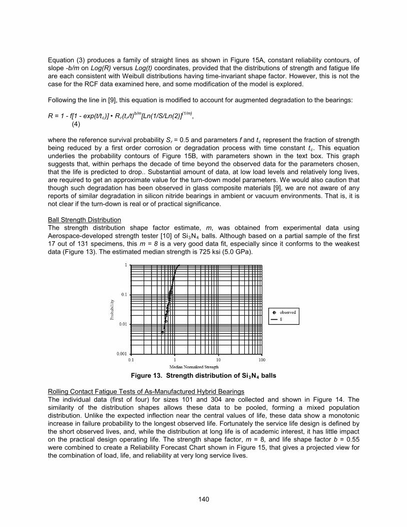
Ball Strength DistributionThe strength distribution shape factor estimate, �, was obtained from experimental data using Aerospace-developed strength tester [10] of Si3N4 balls. Although based on a partial sample of the first 17 out of 131 specimens, this ��B�= is a very good data fit, especially since it conforms to the weakest data (Figure 13). The estimated median strength is 725 ksi (5.0 GPa).
Figure 13. Strength distribution of Si3N4 balls
Rolling Contact Fatigue Tests of As-Manufactured Hybrid BearingsThe individual data (first of four) for sizes 101 and 304 are collected and shown in Figure 14. The similarity of the distribution shapes allows these data to be pooled, forming a mixed population distribution. Unlike the expected inflection near the central values of life, these data show a monotonic increase in failure probability to the longest observed life. Fortunately the service life design is defined by the short observed lives, and, while the distribution at long life is of academic interest, it has little impact on the practical design operating life. The strength shape factor, ��= 8��and life shape factor�$ = 0.55were combined to create a Reliability Forecast Chart shown in Figure 15, that gives a projected view for the combination of load, life, and reliability at very long service lives.
140

Figure 14. Individual probability distributions (left) and combined RCF lifetime distribution (right) of as-manufactured hybrid bearings for 101H and 304H sizes
Rolling Contact Fatigue Tests of Hybrid Bearings with Scarred Si3N4 BallsFigure 16 shows the pronounced reduction of fatigue life and lowered life scatter. However, the monotonic increase of failure probability seen with the pristine bearings is not present with the damaged bearings. The median life of the scarred bearings was about 5% of the pristine bearing life, and there was no similarity observed in the distribution plots
A B Figure 15. Turn-down model for as-manufactured 101H and 304H bearings. A) No turn down,
B) Notional turndown for one particular set of parameters shown here. More data would be needed to confirm or refute if a turn down effect is present in these materials.
Turn-Down Model for 101/304 Hybrid Bearing RCF
10 Yrs
15 yrs
101&304 at 400 ksi
304 at 330 ksi
Median 304 at 400 ksi
50% contour
1:100
1:10000
1:mill ion
1 10 100 1000 10000 10000010.1
11
0.1
0.01
RCF Lifetime - hours
Frac
tion
of M
edia
n N
orm
aliz
ed S
tren
gth
(725
ksi
)
141

Figure 16. Combined lifetime distribution of mixed as-manufactured 101H and 304H bearings and 304H bearings with scarred Si3N4 balls.
Conclusions
Hybrid ball bearings using Si3N4 balls with steel rings are increasingly being used in space mechanism applications due to their high wear resistance and long rolling contact fatigue life. However, qualitative and quantitative reports of the effects of ball defects that cause early fatigue failure are rare. We reportedon our approach to study these effects. Our strategy included characterization of defects encountered in use, generation of similar defects in a laboratory setting, execution of full-scale bearing tests to obtain lifetimes, post-test characterization, and related finite-element modeling to understand the stress aspects of these defects. We have confirmed that at least one type of defect of appropriate size can significantly reduce fatigue life. Our method can be used to evaluate other defects as they occur or are encountered.
Based on recent RCF testing of hybrid bearings with scarred Si3N4 balls, the size (width) of the scars dictates bearing fatigue life, whereas the frequency of scars has a much lesser influence on life. Scanning electron microscopy images from two tests captured the progression of damage leading to inner race spalls. Infant mortality was observed in all hybrid bearings with “large” (100-μm wide) scars on the balls.Every one of those early failures was a result of inner race spall, and no damage growth was observed in the vicinity of the artificial defects on the Si3N4 ball. Post-test microscopy of the scars revealed that the initially sharply-defined edges appear to be smoothed and burnished.
Finite-element modeling work focused on understanding the effects of Si3N4 ball scars on the stress field in the steel raceway during rolling contact. The ball scars change the shape of the stress field, shifting the high von Mises stress region closer to the surface while creating a low stress region directly under the scar. This is a mechanism to create the observed raceway spalls. The modeling supports that the cause of the inner race spalls is the stress riser from rolling over the scar features on the Si3N4 balls.
According to statistical data analysis, the RCF data of as-manufactured bearings for the 101H and 304H bearings exhibited similar lifetime distributions, which allowed pooling the data in a mixed population. The observed fatigue lifetime distributions of the as-manufactured hybrid bearings are highly scattered with aWeibull modulus fit (to the lower portion of the distribution) of $�B�0.55, so the spread of life is over two orders of magnitude. Both data sets exhibited a progressive increase of failure probability with increasing life. This implies a turn-down of probability contours at long life, though experimental data is needed for validation, and the parameters chosen are speculative as shown here. A mathematical model that can forecast such turn-down was described.
The life degradation associated with the artificially damaged bearings amounted to a 95% reduction of themedian life compared with the baseline (as-manufactured) counterparts. Further testing to assess
142
damage effects in hybrid bearings is planned. To date, no infant mortality of the hybrid bearings has been observed in tests with “short” (40-μm wide) scars on the Si3N4 balls.
Some test time savings may result from testing only slightly more than half the test specimens, thus avoiding the longest lived members of the populations. The Reliability Forecast Chart presented in this paper could be a useful tool in estimating load conditions of high projected reliability at long lives.
Acknowledgements
This work was funded by the Independent Research and Development program of The Aerospace Corporation supported by USAF Space and Missile Systems Center (contract no. FA8802-09-C-0001).
References[1] Park, W., et al., “Rolling Contact Fatigue and Load Capacity Tests of M62 Bearing Steel”, 32nd
Aerospace Mechanisms Conference, NASA/CP-1998-207191, pp. 237-251, NASA Kennedy Space Center, FL, 13-15 May 1998.
[2] Popp, M. and Sternagel, R., “Hybrid Ceramic and All Ceramic Anti-Friction Bearings”, Proceedings of the 8th European Space Mechanisms and Tribology Symposium, ESA SP-438, Sept., 1999.
[3] Hutchings, I. M., Tribology: Friction and Wear of Engineering Materials, Arnold, London, 1992.[4] Gibson, H., Moore, C., and Thom, R., “Marshal Space Flight Center High Speed Turbopump
Bearing Test Rig”, Proceedings from the 34th Aerospace Mechanisms Symposium, 10 May, 2000.[5] Kang, J. and Hadfield, M., “Comparison of 4-ball and 5-ball Rolling Contact Fatigue Tests on
Lubricated Si3N4/Steel Contacts”, �������������,���, Vol. 24, No. 8, pp. 595-604, 2003.[6] Warrier, S. Jarmon, D.C., and Chin, H.A., “Finite Element Analysis of the Critical Flaw Size in
Hybrid Silicon Nitride Ball Bearing”, and references therein, Proc. ASME Turboexpo 2000, Paper 2000-GT-65, Munich Germany, 8-11 May 2000.
[7] Hamilton, G. M., “Explicit equations for the stresses beneath sliding spherical contact”, Proc. Instn. Mech. Engrs, 197C, 53-59, 1983.
[8] Johnson, L. G., &���������3�6��� ��������/��������4������4'��������, McGraw-Hill, New York, 1973.
[9] Robinson, E. Y., “A Universal Bivariate Weibull Model for Static and Dynamic Fatigue ReliabilityForecasting,” 2011 ASTM International Symposium on Rolling Element Bearings, STP 1542, pp. 26-46, Anaheim, CA, April 13–15, 2011.
[10] O’Brien, M. J., de la Cruz, A. R., and Nguyen, E. A., “A Novel Proof Test for Silicon Nitride Balls”,A������� ����������������������������, Vol. 94, Issue 2, pp. 597-604, February 2011.
143

144