a synthesizable vhdl model of the exact solution for three-dimensional hyperbolic positioning
TRANSCRIPT

A Synthesizable VHDL Model of the Exact Solution forThree-dimensional Hyperbolic Positioning System
RALPH BUCHER and D. MISRA,*
Department of Electrical and Computer Engineering, New Jersey Center for Wireless and Telecommunication, New Jersey Institute of Technology,Newark, NJ 07102, USA
(Received 1 August 2001; Revised 3 October 2001)
This paper presents a synthesizable VHDL model of a three-dimensional hyperbolic positioning systemalgorithm. The algorithm obtains an exact solution for the three-dimensional location of a mobile giventhe locations of four fixed stations (like a global positioning system [GPS] satellite or a base station in acell) and the signal time of arrival (TOA) from the mobile to each station. The detailed derivation of thesteps required in the algorithm is presented. A VHDL model of the algorithm was implemented andsimulated using the IEEE numeric_std package. Signals were described by a 32-bit vector. Simulationresults predict location of the mobile is off by 1 m for best case and off by 36 m for worst case. A Cþþprogram using real numbers was used as a benchmark for the accuracy and precision of the VHDLmodel. The model can be easily synthesized for low power hardware implementation.
Keywords: Wireless; Positioning system; Time of arrival (TOA); VHDL; GPS
INTRODUCTION
Recently interests have emerged in using wireless
position location for Intelligent Transportation System
applications such as incident management, traffic
routing, fleet management and E-911 telephone service
[1]. Many designs have been proposed to solve the
wireless position location problem [2–4]. Beacon
location approach evaluates the signal strength from a
mobile at many different known locations and determines
the location of mobile. The other position locator
approach is to evaluate the angle-of-arrival of a signal at
two or more base stations, which determines the line of
bearing and ultimately the mobile location is determined.
The most widely used position location technique for
geolocation of mobile users is the hyperbolic position
location technique, also known as the time difference of
arrival (TDOA) position location method. This technique
utilizes cross-correlation process to calculate the
difference in time of arrival (TOA) of a mobile signal
at multiple (two or higher) pairs of stations. This delay
defines a hyperbola of constant range difference from the
receivers, which are located at the foci. Each TDOA
measurement yields a hyperbolic curve along which the
mobile may be positioned. When multiple stations are
used, multiple hyperbolas are formed, and the intersec-
tion of the set of hyperbolas provides the estimated
location of the source.
Many organizations are developing competing products
to comply with the FCC’s E-911 mandate, which requires
US cellular carriers to provide location information of
phone calls, effective October 2001. The accuracy
required is 100 m or better. Many of these products will
implement the above-mentioned TDOA technique for
locating a mobile with varying degrees of accuracy.
Methods for calculating the TDOA and mobile position
have been reviewed previously [1,2]. Some methods
calculate the two-dimensional position and others estimate
the three-dimensional position depending on the degree of
simplicity desired. In this paper, a more detailed derivation
of a set of equations needed to locate the three-
dimensional position of a mobile is presented. We have
considered global positioning system (GPS) [5–8] to
estimate the location. The nominal GPS operational
constellation provides the user with between five and eight
satellites visible from any point on the earth. For better
accuracy four GPS satellite signals are typically used to
compute positions in three dimensions. The detailed
derivation in this work will be the basis for implementing
a positioning algorithm in Cþþ and VHDL. The VHDL
ISSN 1065-514X print/ISSN 1563-5171 online q 2002 Taylor & Francis Ltd
DOI: 10.1080/1065514021000012129
*Corresponding author. E-mail: [email protected]
VLSI Design, 2002 Vol. 15 (2), pp. 507–520

version will utilize the IEEE numeric_std package so it
can be synthesized into an ASIC by anyone seeking a
hardware implementation.
THE ALGORITHM
The essence of the TDOA technique is the equation for the
distance between two points.
d ¼
ffiffiffiffiffiffiffiffiffiffiffiffiffiffiffiffiffiffiffiffiffiffiffiffiffiffiffiffiffiffiffiffiffiffiffiffiffiffiffiffiffiffiffiffiffiffiffiffiffiffiffiffiffiffiffiffiffiffiffiffiffiffiffiffiffiffiffiffiffiffiðx2 2 x1Þ
2 þ ðy2 2 y1Þ2 þ ðz2 2 z1Þ
2
qð1Þ
The distance between a mobile and a station is
determined indirectly by measuring the time it takes for a
signal to reach the station from the mobile. Multiplying
the TOA t by the signal velocity c gives us the distance d.
From now on, R will be used to represent the distance d
since it is the more commonly used notation in TDOA
literature.
We need to solve for the three unknowns x, y and z
(mobile position). Therefore, Eq. (1) is expanded to three
equations when the specific locations of three satellites i, j
and k are given. This requirement can be easily met since
GPS satellites broadcast their exact locations.
cti ¼ Ri ¼
ffiffiffiffiffiffiffiffiffiffiffiffiffiffiffiffiffiffiffiffiffiffiffiffiffiffiffiffiffiffiffiffiffiffiffiffiffiffiffiffiffiffiffiffiffiffiffiffiffiffiffiffiffiffiffiffiffiffiffiffiffiffiðxi 2 xÞ2 þ ðyi 2 yÞ2 þ ðzi 2 zÞ2
qð2Þ
ctj ¼ Rj ¼
ffiffiffiffiffiffiffiffiffiffiffiffiffiffiffiffiffiffiffiffiffiffiffiffiffiffiffiffiffiffiffiffiffiffiffiffiffiffiffiffiffiffiffiffiffiffiffiffiffiffiffiffiffiffiffiffiffiffiffiffiffiffiðxj 2 xÞ2 þ ðyj 2 yÞ2 þ ðzj 2 zÞ2
qð3Þ
ctk ¼ Rk ¼
ffiffiffiffiffiffiffiffiffiffiffiffiffiffiffiffiffiffiffiffiffiffiffiffiffiffiffiffiffiffiffiffiffiffiffiffiffiffiffiffiffiffiffiffiffiffiffiffiffiffiffiffiffiffiffiffiffiffiffiffiffiffiffiffiðxk 2 xÞ2 þ ðyk 2 yÞ2 þ ðzk 2 zÞ2
qð4Þ
where, xi, yi, zi, xj, yj, zj and xk, yk, zk are the position of ith,
jth and kth satellite, respectively and these positions vary
with time.
Unfortunately, solving the three equations for three
unknowns will not lead to a simple and satisfactory
solution because of the square root terms. The solution can
be simplified by adding another satellite l for an additional
equation. In addition, the accuracy of the mobile position
will be further improved if four equations are used. This
requirement is easily met since four GPS satellites are
guaranteed to be in the horizon of any location on earth
[9]. The four equations will be combined to form
expressions for time difference of arrivals (TDOAs) Rij,
Rik, Rkj and Rkl.
Ri 2Rj ¼ Rij ¼
ffiffiffiffiffiffiffiffiffiffiffiffiffiffiffiffiffiffiffiffiffiffiffiffiffiffiffiffiffiffiffiffiffiffiffiffiffiffiffiffiffiffiffiffiffiffiffiffiffiffiffiffiffiffiffiffiffiffiffiffiðxi 2 xÞ2 þ ðyi 2 yÞ2 þ ðzi 2 zÞ2
q
2
ffiffiffiffiffiffiffiffiffiffiffiffiffiffiffiffiffiffiffiffiffiffiffiffiffiffiffiffiffiffiffiffiffiffiffiffiffiffiffiffiffiffiffiffiffiffiffiffiffiffiffiffiffiffiffiffiffiffiffiffiðxj 2 xÞ2 þ ðyj 2 yÞ2 þ ðzj 2 zÞ2
qð5Þ
Ri 2Rk ¼ Rik ¼
ffiffiffiffiffiffiffiffiffiffiffiffiffiffiffiffiffiffiffiffiffiffiffiffiffiffiffiffiffiffiffiffiffiffiffiffiffiffiffiffiffiffiffiffiffiffiffiffiffiffiffiffiffiffiffiffiffiffiffiðxi 2 xÞ2 þðyi 2 yÞ2 þðzi 2 zÞ2
q
2
ffiffiffiffiffiffiffiffiffiffiffiffiffiffiffiffiffiffiffiffiffiffiffiffiffiffiffiffiffiffiffiffiffiffiffiffiffiffiffiffiffiffiffiffiffiffiffiffiffiffiffiffiffiffiffiffiffiffiffiffiffiðxk 2 xÞ2 þðyk 2 yÞ2 þðzk 2 zÞ2
qð6Þ
Rk 2Rj ¼ Rkj ¼
ffiffiffiffiffiffiffiffiffiffiffiffiffiffiffiffiffiffiffiffiffiffiffiffiffiffiffiffiffiffiffiffiffiffiffiffiffiffiffiffiffiffiffiffiffiffiffiffiffiffiffiffiffiffiffiffiffiffiffiffiffiffiðxk 2 xÞ2 þ ðyk 2 yÞ2 þ ðzk 2 zÞ2
q
2
ffiffiffiffiffiffiffiffiffiffiffiffiffiffiffiffiffiffiffiffiffiffiffiffiffiffiffiffiffiffiffiffiffiffiffiffiffiffiffiffiffiffiffiffiffiffiffiffiffiffiffiffiffiffiffiffiffiffiffiffiðxj 2 xÞ2 þ ðyj 2 yÞ2 þ ðzj 2 zÞ2
qð7Þ
Rk 2Rl ¼ Rkl ¼
ffiffiffiffiffiffiffiffiffiffiffiffiffiffiffiffiffiffiffiffiffiffiffiffiffiffiffiffiffiffiffiffiffiffiffiffiffiffiffiffiffiffiffiffiffiffiffiffiffiffiffiffiffiffiffiffiffiffiffiffiffiffiðxk 2 xÞ2 þ ðyk 2 yÞ2 þ ðzk 2 zÞ2
q
2
ffiffiffiffiffiffiffiffiffiffiffiffiffiffiffiffiffiffiffiffiffiffiffiffiffiffiffiffiffiffiffiffiffiffiffiffiffiffiffiffiffiffiffiffiffiffiffiffiffiffiffiffiffiffiffiffiffiffiffiffiðxl 2 xÞ2 þ ðyl 2 yÞ2 þ ðzl 2 zÞ2
qð8Þ
Moving one square root term to the other side gives us:
Rij 2
ffiffiffiffiffiffiffiffiffiffiffiffiffiffiffiffiffiffiffiffiffiffiffiffiffiffiffiffiffiffiffiffiffiffiffiffiffiffiffiffiffiffiffiffiffiffiffiffiffiffiffiffiffiffiffiffiffiffiffiffiffiffiðxi 2 xÞ2 þ ðyi 2 yÞ2 þ ðzi 2 zÞ2
q
¼ 2
ffiffiffiffiffiffiffiffiffiffiffiffiffiffiffiffiffiffiffiffiffiffiffiffiffiffiffiffiffiffiffiffiffiffiffiffiffiffiffiffiffiffiffiffiffiffiffiffiffiffiffiffiffiffiffiffiffiffiffiffiffiffiðxj 2 xÞ2 þ ðyj 2 yÞ2 þ ðzj 2 zÞ2
qð9Þ
Rik 2
ffiffiffiffiffiffiffiffiffiffiffiffiffiffiffiffiffiffiffiffiffiffiffiffiffiffiffiffiffiffiffiffiffiffiffiffiffiffiffiffiffiffiffiffiffiffiffiffiffiffiffiffiffiffiffiffiffiffiffiffiffiffiðxi 2 xÞ2 þ ðyi 2 yÞ2 þ ðzi 2 zÞ2
q
¼ 2
ffiffiffiffiffiffiffiffiffiffiffiffiffiffiffiffiffiffiffiffiffiffiffiffiffiffiffiffiffiffiffiffiffiffiffiffiffiffiffiffiffiffiffiffiffiffiffiffiffiffiffiffiffiffiffiffiffiffiffiffiffiffiffiffiðxk 2 xÞ2 þ ðyk 2 yÞ2 þ ðzk 2 zÞ2
qð10Þ
Rkj 2
ffiffiffiffiffiffiffiffiffiffiffiffiffiffiffiffiffiffiffiffiffiffiffiffiffiffiffiffiffiffiffiffiffiffiffiffiffiffiffiffiffiffiffiffiffiffiffiffiffiffiffiffiffiffiffiffiffiffiffiffiffiffiffiffiðxk 2 xÞ2 þ ðyk 2 yÞ2 þ ðzk 2 zÞ2
q
¼ 2
ffiffiffiffiffiffiffiffiffiffiffiffiffiffiffiffiffiffiffiffiffiffiffiffiffiffiffiffiffiffiffiffiffiffiffiffiffiffiffiffiffiffiffiffiffiffiffiffiffiffiffiffiffiffiffiffiffiffiffiffiffiffiðxj 2 xÞ2 þ ðyj 2 yÞ2 þ ðzj 2 zÞ2
qð11Þ
Rkl 2
ffiffiffiffiffiffiffiffiffiffiffiffiffiffiffiffiffiffiffiffiffiffiffiffiffiffiffiffiffiffiffiffiffiffiffiffiffiffiffiffiffiffiffiffiffiffiffiffiffiffiffiffiffiffiffiffiffiffiffiffiffiffiffiffiðxk 2 xÞ2 þ ðyk 2 yÞ2 þ ðzk 2 zÞ2
q
¼ 2
ffiffiffiffiffiffiffiffiffiffiffiffiffiffiffiffiffiffiffiffiffiffiffiffiffiffiffiffiffiffiffiffiffiffiffiffiffiffiffiffiffiffiffiffiffiffiffiffiffiffiffiffiffiffiffiffiffiffiffiffiffiffiðxl 2 xÞ2 þ ðyl 2 yÞ2 þ ðzl 2 zÞ2
qð12Þ
Squaring both sides produces the following set of
equations:
R2ij 2 2Rij
ffiffiffiffiffiffiffiffiffiffiffiffiffiffiffiffiffiffiffiffiffiffiffiffiffiffiffiffiffiffiffiffiffiffiffiffiffiffiffiffiffiffiffiffiffiffiffiffiffiffiffiffiffiffiffiffiffiffiffiffiffiffiðxi 2 xÞ2 þ ðyi 2 yÞ2 þ ðzi 2 zÞ2
q
þ ðxi 2 xÞ2 þ ðyi 2 yÞ2 þ ðzi 2 zÞ2
¼ ðxj 2 xÞ2 þ ðyj 2 yÞ2 þ ðzj 2 zÞ2 ð13Þ
R2ik 2 2Rik
ffiffiffiffiffiffiffiffiffiffiffiffiffiffiffiffiffiffiffiffiffiffiffiffiffiffiffiffiffiffiffiffiffiffiffiffiffiffiffiffiffiffiffiffiffiffiffiffiffiffiffiffiffiffiffiffiffiffiffiffiffiffiðxi 2 xÞ2 þ ðyi 2 yÞ2 þ ðzi 2 zÞ2
q
þ ðxi 2 xÞ2 þ ðyi 2 yÞ2 þ ðzi 2 zÞ2
¼ ðxk 2 xÞ2 þ ðyk 2 yÞ2 þ ðzk 2 zÞ2 ð14Þ
R2kj 2 2Rkj
ffiffiffiffiffiffiffiffiffiffiffiffiffiffiffiffiffiffiffiffiffiffiffiffiffiffiffiffiffiffiffiffiffiffiffiffiffiffiffiffiffiffiffiffiffiffiffiffiffiffiffiffiffiffiffiffiffiffiffiffiffiffiffiffiðxk 2 xÞ2 þ ðyk 2 yÞ2 þ ðzk 2 zÞ2
q
þ ðxk 2 xÞ2 þ ðyk 2 yÞ2 þ ðzk 2 zÞ2
¼ ðxj 2 xÞ2 þ ðyj 2 yÞ2 þ ðzj 2 zÞ2 ð15Þ
R. BUCHER AND D. MISRA508
R2kl 2 2Rkl
ffiffiffiffiffiffiffiffiffiffiffiffiffiffiffiffiffiffiffiffiffiffiffiffiffiffiffiffiffiffiffiffiffiffiffiffiffiffiffiffiffiffiffiffiffiffiffiffiffiffiffiffiffiffiffiffiffiffiffiffiffiffiffiffiðxk 2 xÞ2 þ ðyk 2 yÞ2 þ ðzk 2 zÞ2
q
þ ðxk 2 xÞ2 þ ðyk 2 yÞ2 þ ðzk 2 zÞ2
¼ ðxl 2 xÞ2 þ ðyl 2 yÞ2 þ ðzl 2 zÞ2 ð16Þ
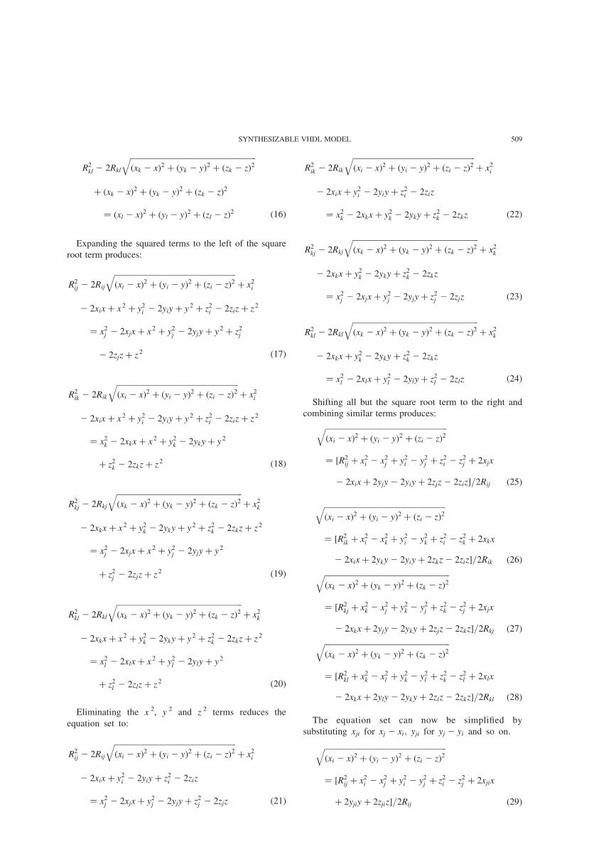
Expanding the squared terms to the left of the square
root term produces:
R2ij 2 2Rij
ffiffiffiffiffiffiffiffiffiffiffiffiffiffiffiffiffiffiffiffiffiffiffiffiffiffiffiffiffiffiffiffiffiffiffiffiffiffiffiffiffiffiffiffiffiffiffiffiffiffiffiffiffiffiffiffiffiffiffiffiffiffiðxi 2 xÞ2 þ ðyi 2 yÞ2 þ ðzi 2 zÞ2
qþ x2
i
2 2xix þ x2 þ y2i 2 2yiy þ y 2 þ z2
i 2 2ziz þ z2
¼ x2j 2 2xjx þ x2 þ y2
j 2 2yjy þ y 2 þ z2j
2 2zjz þ z2 ð17Þ
R2ik 2 2Rik
ffiffiffiffiffiffiffiffiffiffiffiffiffiffiffiffiffiffiffiffiffiffiffiffiffiffiffiffiffiffiffiffiffiffiffiffiffiffiffiffiffiffiffiffiffiffiffiffiffiffiffiffiffiffiffiffiffiffiffiffiffiffiðxi 2 xÞ2 þ ðyi 2 yÞ2 þ ðzi 2 zÞ2
qþ x2
i
2 2xix þ x2 þ y2i 2 2yiy þ y 2 þ z2
i 2 2ziz þ z2
¼ x2k 2 2xkx þ x2 þ y2
k 2 2yky þ y 2
þ z2k 2 2zkz þ z2 ð18Þ
R2kj 2 2Rkj
ffiffiffiffiffiffiffiffiffiffiffiffiffiffiffiffiffiffiffiffiffiffiffiffiffiffiffiffiffiffiffiffiffiffiffiffiffiffiffiffiffiffiffiffiffiffiffiffiffiffiffiffiffiffiffiffiffiffiffiffiffiffiffiffiðxk 2 xÞ2 þ ðyk 2 yÞ2 þ ðzk 2 zÞ2
qþ x2
k
2 2xkx þ x2 þ y2k 2 2yky þ y 2 þ z2
k 2 2zkz þ z2
¼ x2j 2 2xjx þ x2 þ y2
j 2 2yjy þ y 2
þ z2j 2 2zjz þ z2 ð19Þ
R2kl 2 2Rkl
ffiffiffiffiffiffiffiffiffiffiffiffiffiffiffiffiffiffiffiffiffiffiffiffiffiffiffiffiffiffiffiffiffiffiffiffiffiffiffiffiffiffiffiffiffiffiffiffiffiffiffiffiffiffiffiffiffiffiffiffiffiffiffiffiðxk 2 xÞ2 þ ðyk 2 yÞ2 þ ðzk 2 zÞ2
qþ x2
k
2 2xkx þ x2 þ y2k 2 2yky þ y 2 þ z2
k 2 2zkz þ z2
¼ x2l 2 2xlx þ x2 þ y2
l 2 2yly þ y 2
þ z2l 2 2zlz þ z2 ð20Þ
Eliminating the x 2, y 2 and z 2 terms reduces the
equation set to:
R2ij 2 2Rij
ffiffiffiffiffiffiffiffiffiffiffiffiffiffiffiffiffiffiffiffiffiffiffiffiffiffiffiffiffiffiffiffiffiffiffiffiffiffiffiffiffiffiffiffiffiffiffiffiffiffiffiffiffiffiffiffiffiffiffiffiffiffiðxi 2 xÞ2 þ ðyi 2 yÞ2 þ ðzi 2 zÞ2
qþ x2
i
2 2xix þ y2i 2 2yiy þ z2
i 2 2ziz
¼ x2j 2 2xjx þ y2
j 2 2yjy þ z2j 2 2zjz ð21Þ
R2ik 2 2Rik
ffiffiffiffiffiffiffiffiffiffiffiffiffiffiffiffiffiffiffiffiffiffiffiffiffiffiffiffiffiffiffiffiffiffiffiffiffiffiffiffiffiffiffiffiffiffiffiffiffiffiffiffiffiffiffiffiffiffiffiffiffiffiðxi 2 xÞ2 þ ðyi 2 yÞ2 þ ðzi 2 zÞ2
qþ x2
i
2 2xix þ y2i 2 2yiy þ z2
i 2 2ziz
¼ x2k 2 2xkx þ y2
k 2 2yky þ z2k 2 2zkz ð22Þ
R2kj 2 2Rkj
ffiffiffiffiffiffiffiffiffiffiffiffiffiffiffiffiffiffiffiffiffiffiffiffiffiffiffiffiffiffiffiffiffiffiffiffiffiffiffiffiffiffiffiffiffiffiffiffiffiffiffiffiffiffiffiffiffiffiffiffiffiffiffiffiðxk 2 xÞ2 þ ðyk 2 yÞ2 þ ðzk 2 zÞ2
qþ x2
k
2 2xkx þ y2k 2 2yky þ z2
k 2 2zkz
¼ x2j 2 2xjx þ y2
j 2 2yjy þ z2j 2 2zjz ð23Þ
R2kl 2 2Rkl
ffiffiffiffiffiffiffiffiffiffiffiffiffiffiffiffiffiffiffiffiffiffiffiffiffiffiffiffiffiffiffiffiffiffiffiffiffiffiffiffiffiffiffiffiffiffiffiffiffiffiffiffiffiffiffiffiffiffiffiffiffiffiffiffiðxk 2 xÞ2 þ ðyk 2 yÞ2 þ ðzk 2 zÞ2
qþ x2
k
2 2xkx þ y2k 2 2yky þ z2
k 2 2zkz
¼ x2l 2 2xlx þ y2
l 2 2yly þ z2l 2 2zlz ð24Þ
Shifting all but the square root term to the right and
combining similar terms produces:ffiffiffiffiffiffiffiffiffiffiffiffiffiffiffiffiffiffiffiffiffiffiffiffiffiffiffiffiffiffiffiffiffiffiffiffiffiffiffiffiffiffiffiffiffiffiffiffiffiffiffiffiffiffiffiffiffiffiffiffiffiffiðxi 2 xÞ2 þ ðyi 2 yÞ2 þ ðzi 2 zÞ2
q¼ ½R2
ij þ x2i 2 x2
j þ y2i 2 y2
j þ z2i 2 z2
j þ 2xjx
2 2xix þ 2yjy 2 2yiy þ 2zjz 2 2ziz�=2Rij ð25Þ
ffiffiffiffiffiffiffiffiffiffiffiffiffiffiffiffiffiffiffiffiffiffiffiffiffiffiffiffiffiffiffiffiffiffiffiffiffiffiffiffiffiffiffiffiffiffiffiffiffiffiffiffiffiffiffiffiffiffiffiffiffiffiðxi 2 xÞ2 þ ðyi 2 yÞ2 þ ðzi 2 zÞ2
q¼ ½R2
ik þ x2i 2 x2
k þ y2i 2 y2
k þ z2i 2 z2
k þ 2xkx
2 2xix þ 2yky 2 2yiy þ 2zkz 2 2ziz�=2Rik ð26Þffiffiffiffiffiffiffiffiffiffiffiffiffiffiffiffiffiffiffiffiffiffiffiffiffiffiffiffiffiffiffiffiffiffiffiffiffiffiffiffiffiffiffiffiffiffiffiffiffiffiffiffiffiffiffiffiffiffiffiffiffiffiffiffiðxk 2 xÞ2 þ ðyk 2 yÞ2 þ ðzk 2 zÞ2
q¼ ½R2
kj þ x2k 2 x2
j þ y2k 2 y2
j þ z2k 2 z2
j þ 2xjx
2 2xkx þ 2yjy 2 2yky þ 2zjz 2 2zkz�=2Rkj ð27Þffiffiffiffiffiffiffiffiffiffiffiffiffiffiffiffiffiffiffiffiffiffiffiffiffiffiffiffiffiffiffiffiffiffiffiffiffiffiffiffiffiffiffiffiffiffiffiffiffiffiffiffiffiffiffiffiffiffiffiffiffiffiffiffiðxk 2 xÞ2 þ ðyk 2 yÞ2 þ ðzk 2 zÞ2
q¼ ½R2
kl þ x2k 2 x2
l þ y2k 2 y2
l þ z2k 2 z2
l þ 2xlx
2 2xkx þ 2yly 2 2yky þ 2zlz 2 2zkz�=2Rkl ð28Þ
The equation set can now be simplified by
substituting xji for xj 2 xi; yji for yj 2 yi and so on.
ffiffiffiffiffiffiffiffiffiffiffiffiffiffiffiffiffiffiffiffiffiffiffiffiffiffiffiffiffiffiffiffiffiffiffiffiffiffiffiffiffiffiffiffiffiffiffiffiffiffiffiffiffiffiffiffiffiffiffiffiffiffiðxi 2 xÞ2 þ ðyi 2 yÞ2 þ ðzi 2 zÞ2
q¼ ½R2
ij þ x2i 2 x2
j þ y2i 2 y2
j þ z2i 2 z2
j þ 2xjix
þ 2yjiy þ 2zjiz�=2Rij ð29Þ
SYNTHESIZABLE VHDL MODEL 509

ffiffiffiffiffiffiffiffiffiffiffiffiffiffiffiffiffiffiffiffiffiffiffiffiffiffiffiffiffiffiffiffiffiffiffiffiffiffiffiffiffiffiffiffiffiffiffiffiffiffiffiffiffiffiffiffiffiffiffiffiffiffiðxi 2 xÞ2 þ ðyi 2 yÞ2 þ ðzi 2 zÞ2
q¼ ½R2
ik þ x2i 2 x2
k þ y2i 2 y2
k þ z2i 2 z2
k þ 2xkix
þ 2ykiy þ 2zkiz�=2Rik ð30Þ
ffiffiffiffiffiffiffiffiffiffiffiffiffiffiffiffiffiffiffiffiffiffiffiffiffiffiffiffiffiffiffiffiffiffiffiffiffiffiffiffiffiffiffiffiffiffiffiffiffiffiffiffiffiffiffiffiffiffiffiffiffiffiffiffiðxk 2 xÞ2 þ ðyk 2 yÞ2 þ ðzk 2 zÞ2
q¼ ½R2
kj þ x2k 2 x2
j þ y2k 2 y2
j þ z2k 2 z2
j þ 2xjkx
þ 2yjky þ 2zjkz�=2Rkj ð31Þ
ffiffiffiffiffiffiffiffiffiffiffiffiffiffiffiffiffiffiffiffiffiffiffiffiffiffiffiffiffiffiffiffiffiffiffiffiffiffiffiffiffiffiffiffiffiffiffiffiffiffiffiffiffiffiffiffiffiffiffiffiffiffiffiffiðxk 2 xÞ2 þ ðyk 2 yÞ2 þ ðzk 2 zÞ2
q¼ ½R2
kl þ x2k 2 x2
l þ y2k 2 y2
l þ z2k 2 z2
l þ 2xlkx
þ 2ylky þ 2zlkz�=2Rkl ð32Þ
Equations (5)–(8) are now in a useful arrangement.
Equations (29)–(32), when squared, are intersecting
hyperboloids. By equating Eqs. (29) and (30) to form
Eq. (33), we can derive a plane equation in the form of
y ¼ Ax þ By þ C by rearranging the terms as shown in
Eqs. (34) and (35).
½R2ijþx2
i 2x2j þy2
i 2y2j þz2
i 2z2j þ2xjixþ2yjiyþ2zjiz�=2Rij
¼½R2ikþx2
i 2x2k þy2
i 2y2k þz2
i
2z2k þ2xkixþ2ykiyþ2zkiz�=2Rik ð33Þ
Rik½R2ijþx2
i 2x2j þy2
i 2y2j þz2
i 2z2j �=2
2Rij½R2ikþx2
i 2x2k þy2
i 2y2k þz2
i 2z2k�=2
¼Rij½xkixþykiyþzkiz�2Rik½xjixþyjiyþzjiz� ð34Þ
x½Rijxki2Rikxji�þy½Rijyki2Rikxji�þz½Rijzki2Rikzji�
¼Rik½R2ijþx2
i 2x2j þy2
i 2y2j þz2
i 2z2j �=2
2Rij½R2ikþx2
i 2x2k þy2
i 2y2k þz2
i 2z2k�=2 ð35Þ
Equation (35) is now in the desired form of a plane
equation as follows:
y ¼ Ax þ Bz þ C ð36Þ
where
A ¼Rikxji 2 Rijxki
Rijyki 2 Rikyji
� �ð37Þ
and
B ¼Rikzji 2 Rijzki
Rijyki 2 Rikyji
� �ð38Þ
and
C ¼Rik½R
2ij þ x2
i 2 x2j þ y2
i 2 y2j þ z2
i 2 z2j �2 Rij½R
2ik þ x2
i 2 x2k þ y2
i 2 y2k þ z2
i 2 z2k�
2½Rijyki 2 Rikyji�
ð39Þ
Similarly, equating Eqs. (31) and (32) produces a
second plane equation y ¼ Dx þ Ey þ F: The resulting
set of equations are:
y ¼ Dx þ Ez þ F ð40Þ
where
D ¼Rklxjk 2 Rkjxlk
Rkjylk 2 Rklyjk
� �ð41Þ
and
E ¼Rklzjk 2 Rkjzlk
Rkjylk 2 Rklyjk
� �ð42Þ
and
F¼Rkl½R
2kjþx2
k 2x2j þy2
k 2y2j þz2
k 2z2j �2Rkj½R
2klþx2
k 2x2l þy2
k 2y2l þz2
k 2z2l �
2½Rkjylk2Rklyjk�
ð43Þ
Equating the plane Eqs. (36) and (40) produces a linear
equation for x in terms of z.
Ax þ Bx þ C ¼ Dx þ Ez þ F ð44Þ
x ¼ Gz þ H ð45Þ
where
G ¼E 2 B
A 2 Dð46Þ
and
H ¼F 2 C
A 2 Dð47Þ
Substituting Eq. (45) back into Eq. (36) produces a
linear equation for y in terms of z.
y ¼ AðGz þ HÞ þ Bz þ C ð48Þ
y ¼ Iz þ J ð49Þ
where
I ¼ AG þ B ð50Þ
and
J ¼ AH þ C ð51Þ
R. BUCHER AND D. MISRA510

Equations (45) and (49) are now substituted back
into Eq. (30) to derive the position z.
2Rik
ffiffiffiffiffiffiffiffiffiffiffiffiffiffiffiffiffiffiffiffiffiffiffiffiffiffiffiffiffiffiffiffiffiffiffiffiffiffiffiffiffiffiffiffiffiffiffiffiffiffiffiffiffiffiffiffiffiffiffiffiffiffiffiffiffiffiffiffiffiffiffiffiffiffiffiffiffiffiffiffiffiffiffiffiffiffiffiffiffiffiffiðxi 2 ðGz þ HÞÞ2 þ ðyi 2 ðIz þ JÞÞ2 þ ðzi 2 zÞ2
q
¼ ½R2ik þ x2
i 2 x2k þ y2
i 2 y2k þ z2
i 2 z2k
þ 2xkiðGz þ HÞ þ 2ykiðIz þ JÞ þ 2zkiz� ð52Þ
2Rik
ffiffiffiffiffiffiffiffiffiffiffiffiffiffiffiffiffiffiffiffiffiffiffiffiffiffiffiffiffiffiffiffiffiffiffiffiffiffiffiffiffiffiffiffiffiffiffiffiffiffiffiffiffiffiffiffiffiffiffiffiffiffiffiffiffiffiffiffiffiffiffiffiffiffiffiffiffiffiffiffiffiffiffiffiffiffiffiffiffiffiffiffiffiffiffiffiffiffiffiffiffiffiffiðG2z 2 2 2Gzðxi 2 HÞ þ ðxi 2 HÞ2Þ þ ðI 2z2 2 2Izðyi 2 JÞ þ ðyi 2 JÞ2Þ þ ðz 2 2 2ziz þ z2
i Þ
p
¼ Lz þ K ð53Þ
where
K ¼ R2ik þ x2
i 2 x2k þ y2
i 2 y2k þ z2
i 2 z2k þ 2xkiH
þ 2ykiJ ð54Þ
and
L ¼ 2½xkiG þ ykiI þ 2zki� ð55Þ
4R2ik½G
2z2 þ I 2z2 þ z2 2 2Gzðxi 2 HÞ2 2Izðyi 2 JÞ
2 2ziz þ ðxi 2 HÞ2 þ ðyi 2 JÞ2 þ z2i �
¼ L2z2 þ 2KLz þ K 2ð56Þ
4R2ik½G
2 þ I 2 þ 1�z2 2 8R2ik½Gðxi 2 HÞ þ Iðyi 2 JÞ
þ zi�z þ 4R2ik½ðxi 2 HÞ2 þ ðyi 2 JÞ2 þ z2
i �
¼ L2z2 þ 2KLz þ K 2ð57Þ
To obtain z, Eq. (57) is rearranged into a binomial
equation.
Mz2 2 Nz þ O ¼ 0 ð58Þ
where
M ¼ 4R2ik½G
2 þ I 2 þ 1�2 L2 ð59Þ
and
N ¼ 8R2ik½Gðxi 2 HÞ þ Iðyi 2 JÞ þ zi� þ 2LK ð60Þ
and
O ¼ 4R2ik½ðxi 2 HÞ2 þ ðyi 2 JÞ2 þ z2
i �2 K 2 ð61Þ
The solution for z is:
z ¼N
2M^
ffiffiffiffiffiffiffiffiffiffiffiffiffiffiffiffiffiffiffiffiffiffiffiffiffiN
2M
� �2
2O
M
sð62Þ
The z coordinate can be put back into the linear Eqs. (45)
and (49) to solve for the coordinates x and y.
VHDL MODEL
The equations for the x, y and z position of the mobile was
modeled using VHDL. The numeric_std package was
used to construct the VHDL model that was readily
synthesized into a low power digital circuit. The details of
the circuit are beyond the scope of this paper. The input
signals of the model are the x, y, z positions of four GPS
satellites i, j, k, l in meters, and the signal TOAs from the
individual satellites to the mobile in nanoseconds. The
input signal assignments are xi, yi, zi, ti, xj, yj, zj, tj, xk, yk,
zk, tk, xl, yl, zl and tl.
GPS satellite altitudes are approximately 10,900
nautical miles (20,186,800 m). Therefore, the TOA range
is roughly 6,700,000–7,600,000 ns. This means the input
signals can be adequately described by a 32-bit vector. In
order to perform signed arithmetic operations, the input
signal assignments are of type SIGNED. The binary
representation for negative numbers is 2’s complement.
The TDOAs are converted to distances by multiplying
them by the binary representation of 100,000, and then
dividing the result by the binary representation of
333,564 ns/m.
Since all signal and variable assignments are vectors
representing integers, a method for maintaining adequate
precision in divide and square root operations is needed.
This will be achieved by multiplying the numerator by the
binary representation of 1:0 £ 1010 in divide operations.
This method is preferred to using decimal point notation to
decrease the complexity of the model. However, the length
of the vectors increases for successive multiplication
operations, leading to a 200-bit vector for the interim
value O.
The numeric_std package does not contain an over-
loaded square root operator. Therefore, Dijkstra’s bisec-
tion algorithm [10] is used to compute the integer square
root of a positive integer represented by a 64-bit vector.
Sixty four bits is deemed adequate since the position z and
the square root term cannot be larger than 32 bits by
definition.
The square root operation gives two values for z, so the
output signals z1, z2, x1, x2, y1, y2 are for two possible
mobile positions. The z value representing the mobile
position can be determined by using a fifth satellite, or
checking if the value is in the horizon of the four satellites
relative to earth. The details of the VHDL model of the
algorithm are provided in Appendix A.
SYNTHESIZABLE VHDL MODEL 511
TESTING THE MODEL
Accolade’s demonstration edition of PeakVHDL was used
to compile the model and run simulations. The model was
also compiled and synthesized with Mentor Graphics’
AUTOLOGIC II [11] in low power mode to ensure the
model was synthesizable. A high level schematic was
generated (not shown here) using AUTOLOGIC’s default
component library.
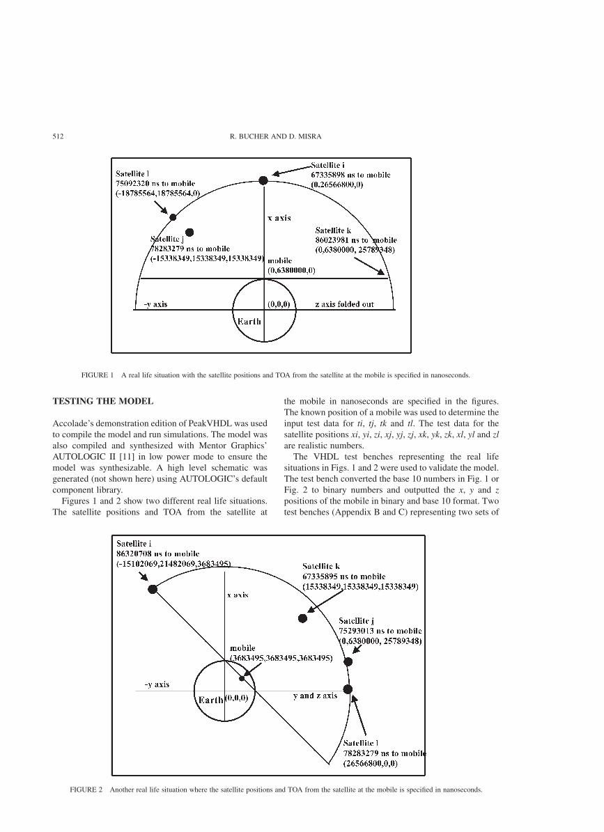
Figures 1 and 2 show two different real life situations.
The satellite positions and TOA from the satellite at
the mobile in nanoseconds are specified in the figures.
The known position of a mobile was used to determine the
input test data for ti, tj, tk and tl. The test data for the
satellite positions xi, yi, zi, xj, yj, zj, xk, yk, zk, xl, yl and zl
are realistic numbers.
The VHDL test benches representing the real life
situations in Figs. 1 and 2 were used to validate the model.
The test bench converted the base 10 numbers in Fig. 1 or
Fig. 2 to binary numbers and outputted the x, y and z
positions of the mobile in binary and base 10 format. Two
test benches (Appendix B and C) representing two sets of
FIGURE 1 A real life situation with the satellite positions and TOA from the satellite at the mobile is specified in nanoseconds.
FIGURE 2 Another real life situation where the satellite positions and TOA from the satellite at the mobile is specified in nanoseconds.
R. BUCHER AND D. MISRA512
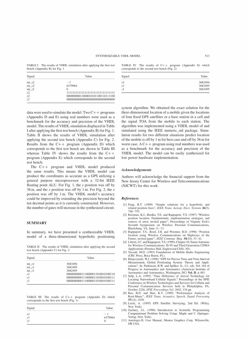
data were used to simulate the model. Two Cþþ programs
(Appendix D and E) using real numbers were used as a
benchmark for the accuracy and precision of the VHDL
model. The results of VHDL simulation displayed in Table
I after applying the first test bench (Appendix B) for Fig. 1.
Table II shows the results of VHDL simulation after
applying the second test bench (Appendix C) for Fig. 2.
Results from the Cþþ program (Appendix D) which
corresponds to the first test bench are shown in Table III
whereas Table IV shows the results from the Cþþ
program (Appendix E) which corresponds to the second
test bench.
The Cþþ program and VHDL model produced
the same results. This means the VHDL model can
produce the coordinates as accurate as a GPS utilizing a
general purpose microprocessor with a 32-bit IEEE
floating point ALU. For Fig. 1, the y position was off by
36 m, and the x position was off by 1 m. For Fig. 2, the x
position was off by 1 m. The VHDL model’s accuracy
could be improved by extending the precision beyond the
ten decimal points as it is currently constructed. However,
the number of gates will increase in the synthesized circuit.
SUMMARY
In summary, we have presented a synthesizable VHDL
model of a three-dimensional hyperbolic positioning
system algorithm. We obtained the exact solution for the
three-dimensional location of a mobile given the locations
of four fixed GPS satellites or a base station in a cell and
the signal TOA from the mobile to each station. The
algorithm was implemented using a VHDL model of and
simulated using the IEEE numeric_std package. Simu-
lation results for two different situations predict location
of the mobile is off by 1 m for best case and off by 36 m for
worst case. A Cþþ program using real numbers was used
as a benchmark for the accuracy and precision of the
VHDL model. The model can be easily synthesized for
low power hardware implementation.
Acknowledgements
Authors will acknowledge the financial support from the
New Jersey Center for Wireless and Telecommunications
(NJCWT) for this work.
References
[1] Fang, B.T. (1990) “Simple solutions for a hyperbolic andrelated position fixes”, IEEE Trans. Aerosp. Elect. Systems 26(5),748–753.
[2] Krizman, K.J., Biedka, T.E. and Rappaport, T.S. (1997) “Wirelessposition location: Fundamentals, implementation strategies, andsources of error, invited paper”, Proceedings of Virginia Tech’sSeventh Symposium on Wireless Personal Communications,Blacksburg, VA, June 11–13.
[3] Rappaport, T.S., Reed, J.H. and Woerner, B.D. (1996) “Positionlocation using Wireless Communications on Highways of theFuture, invited paper”, IEEE Commun. Mag. 34(10), 33–41.
[4] Liberti, J.C. and Rappaport, T.S. (1999), Chapter 10, Smart Antennasfor Wireless Communications: IS-95 and Third Generation CDMAApplications (Prentice Hall, Englewood Cliffs, NJ).
[5] Yacoub, M.D. (1993) Foundations of Mobile Radio Engineering(CRC Press, Boca Raton, FL).
[6] Klepczynski, W.J. (1996) “GPS for Precise Time and Time IntervalMeasurement, Global Positioning System: Theory and Appli-cations”, In: Parkinson, B.W. and Spilker, Jr., J.J., eds, Vol. 164 ofProgress in Astronautics and Aeronautics (American Institute ofAeronautics and Astronautics, Washington, DC) Vol. II, p 483.
[7] Stilp, L.A. (1995) “Time Difference of Arrival Technology forLocating Narrowband Cellular Signals.” Proceedings of the SPIEConference on Wireless Technologies and Services for Cellular andPersonal Communication Services held in Philadelphia, PA,October 2226, SPIE Proceedings Vol. 2602, 134 pp.
[8] Rao, B.D. and Hari, K.V. (1989) “Performance Analysis ofRoot-Music”, IEEE Trans. Acoustics, Speech, Signal Processing37(12), 1939.
[9] Leick, A. (1995) GPS Satellite Surveying, 2nd Ed. (Wiley,New York).
[10] Zachary, J.L. (1996) Introduction to Scientific ProgrammingComputational Problem Solving Using: Maple and C (Springer-Verlag, New York).
[11] Autologic-II, User Manual, Mentor Graphics Corp, Wilsonville,OR USA.
TABLE I The results of VHDL simulation after applying the first testbench (Appendix B) for Fig. 1
Signal Value
int_x2 21int_y2 6379964int_z2 0x2 11111111111111111111111111111111y2 00000000011000010101100110111100z2 00000000000000000000000000000000
TABLE II The results of VHDL simulation after applying the secondtest bench (Appendix C) for Fig. 2
Signal Value
int_x1 3683494int_y1 3683495int_z1 3682495x1 00000000001110000011010010100110y1 00000000001110000011010010100111z1 00000000001110000011010010100111
TABLE III The results of Cþþ program (Appendix D) whichcorresponds to the first test bench (Fig. 1)
Signal Value
x1 21y1 6379964z1 0
TABLE IV The results of Cþþ program (Appendix E) whichcorresponds to the second test bench (Fig. 2)
Signal Value
x1 3683494y1 3683495z1 3683495
SYNTHESIZABLE VHDL MODEL 513

APPENDIX A
R. BUCHER AND D. MISRA514

SYNTHESIZABLE VHDL MODEL 515

APPENDIX B
R. BUCHER AND D. MISRA516
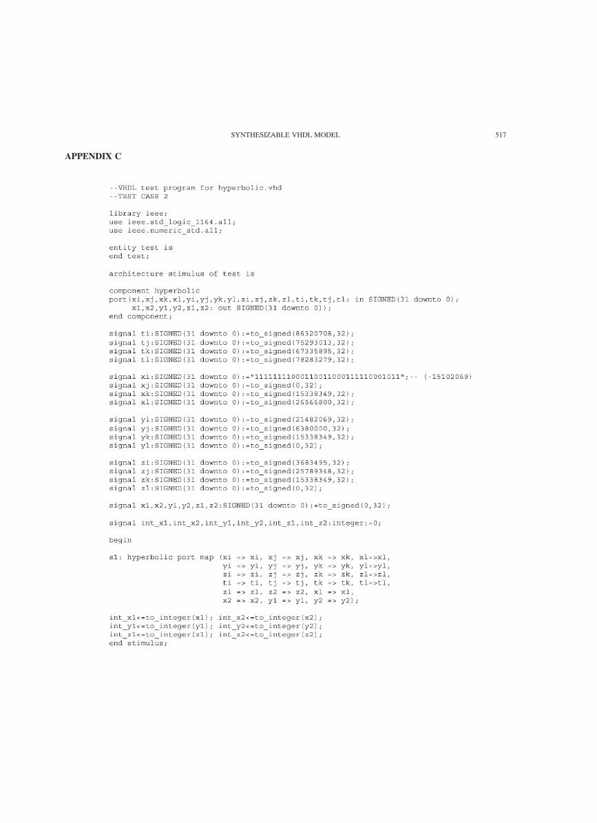
APPENDIX C
SYNTHESIZABLE VHDL MODEL 517
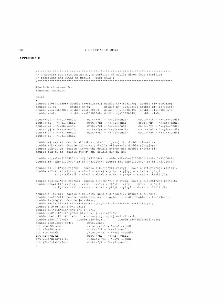
APPENDIX D
R. BUCHER AND D. MISRA518

APPENDIX E
SYNTHESIZABLE VHDL MODEL 519

Ralph Bucher received his B.S. in Engineering Manage-
ment form University of Missouri-Rolla in 1987 and his
M.S. in Computer Engineering from New Jersey Institute
of Technology in 2000. He is currently with Lucent
Technologies at Whippany, New Jersey. His current
interests are in DSL, ethernet and ATM circuits. From
1988 to 1998 he worked at Caterpillar Inc., Peoria, IL.
Durga Misra has received his M.S. and Ph.D. degrees
both in Electrical Engineering from University of
Waterloo, Waterloo, Canada in 1985 and 1988, respec
tively. Since 1988 he has been with the department of
Electrical and Computer Engineering at New Jersey
Institute of Technology where he is now a Professor. In
1997 he was on a research leave at the VLSI Research
Department of Bell Laboratories, Lucent Technologies at
Murray Hill, New Jersey. His current research interests
include low power CMOS circuit design and CMOS
device reliability. He is an Associate Editor of IEEE
Circuits and Devices Magazine and a senior member of
IEEE. He is also a member of the Electrochemical Society,
SPIE, and Sigma Xi.
R. BUCHER AND D. MISRA520

International Journal of
AerospaceEngineeringHindawi Publishing Corporationhttp://www.hindawi.com Volume 2010
RoboticsJournal of
Hindawi Publishing Corporationhttp://www.hindawi.com Volume 2014
Hindawi Publishing Corporationhttp://www.hindawi.com Volume 2014
Active and Passive Electronic Components
Control Scienceand Engineering
Journal of
Hindawi Publishing Corporationhttp://www.hindawi.com Volume 2014
International Journal of
RotatingMachinery
Hindawi Publishing Corporationhttp://www.hindawi.com Volume 2014
Hindawi Publishing Corporation http://www.hindawi.com
Journal ofEngineeringVolume 2014
Submit your manuscripts athttp://www.hindawi.com
VLSI Design
Hindawi Publishing Corporationhttp://www.hindawi.com Volume 2014
Hindawi Publishing Corporationhttp://www.hindawi.com Volume 2014
Shock and Vibration
Hindawi Publishing Corporationhttp://www.hindawi.com Volume 2014
Civil EngineeringAdvances in
Acoustics and VibrationAdvances in
Hindawi Publishing Corporationhttp://www.hindawi.com Volume 2014
Hindawi Publishing Corporationhttp://www.hindawi.com Volume 2014
Electrical and Computer Engineering
Journal of
Advances inOptoElectronics
Hindawi Publishing Corporation http://www.hindawi.com
Volume 2014
The Scientific World JournalHindawi Publishing Corporation http://www.hindawi.com Volume 2014
SensorsJournal of
Hindawi Publishing Corporationhttp://www.hindawi.com Volume 2014
Modelling & Simulation in EngineeringHindawi Publishing Corporation http://www.hindawi.com Volume 2014
Hindawi Publishing Corporationhttp://www.hindawi.com Volume 2014
Chemical EngineeringInternational Journal of Antennas and
Propagation
International Journal of
Hindawi Publishing Corporationhttp://www.hindawi.com Volume 2014
Hindawi Publishing Corporationhttp://www.hindawi.com Volume 2014
Navigation and Observation
International Journal of
Hindawi Publishing Corporationhttp://www.hindawi.com Volume 2014
DistributedSensor Networks
International Journal of