digital design with synthesizable vhdl - columbia …sedwards/classes/2012/4840/vhdl.pdf · digital...
TRANSCRIPT

Digital Design with Synthesizable VHDL
Prof. Stephen A. Edwards
Columbia University
Spring 2012

Combinational Logic in a Dataflow Style
Hierarchy: Instantiating Components (entities)
Combinational Logic in a Procedural Style
Sequential Logic
FSMs
Summary of the Three Modeling Styles
Ten Commandments of VHDL
Writing Testbenches
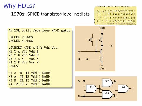
Why HDLs?1970s: SPICE transistor-level netlists
An XOR built from four NAND gates
.MODEL P PMOS
.MODEL N NMOS
.SUBCKT NAND A B Y Vdd VssM1 Y A Vdd Vdd PM2 Y B Vdd Vdd PM3 Y A X Vss NM4 X B Vss Vss N.ENDS
X1 A B I1 Vdd 0 NANDX2 A I1 I2 Vdd 0 NANDX3 B I1 I3 Vdd 0 NANDX4 I2 I3 Y Vdd 0 NAND
Vss
Y
Vdd
A
B
X1
X2
X3
X4
A
B
I1
I2
I3
Y
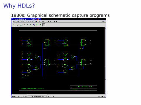
Why HDLs?
1980s: Graphical schematic capture programs

Why HDLs?1990s: HDLs and Logic Synthesis
library ieee;use ieee.std_logic_1164.all;use ieee.numeric_std.all;
entity ALU isport(A:in unsigned(1 downto 0);
B:in unsigned(1 downto 0);
Sel: in unsigned(1 downto 0);Res: out unsigned(1 downto 0));
end ALU;architecture behv of ALU is begin
process (A,B,Sel) begincase Sel is
when "00" => Res <= A + B;when "01" => Res <= A + (not B) + 1;when "10" => Res <= A and B;when "11" => Res <= A or B;when others => Res <= "XX";
end case;end process;
end behv;

Two Separate but Equal Languages
Verilog and VHDLVerilog: More succinct, less flexible, really messyVHDL: Verbose, very (too?) flexible, fairly messyPart of languages people actually use identical.Every synthesis system supports both.
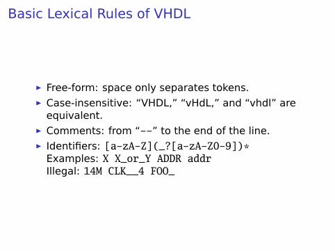
Basic Lexical Rules of VHDL
É Free-form: space only separates tokens.É Case-insensitive: “VHDL,” “vHdL,” and “vhdl” are
equivalent.É Comments: from “--” to the end of the line.É Identifiers: [a-zA-Z](_?[a-zA-Z0-9])*
Examples: X X_or_Y ADDR addrIllegal: 14M CLK__4 FOO_

Literals in VHDL
É Decimal integers∗: 1 42 153_1203É Based integers∗: 2#1_0010# 16#F001D#É Characters: ’0’ ’1’ ’X’É Strings: "101011" "XXXXXX"É Bit string literals∗: B"1001_0101" X"95" mean"10010101"
∗Underscores added for readability are ignored

Combinational Logic in a Dataflow Style

Bits
Logical True False
Binary 1 0
Voltage 1.65–3.3V 0–1.65V
Timing Diagram
VHDL ’1’ ’0’
In VHDL, zeros and ones on wires are members of anenumerated type. They are not Boolean.

The std_logic_1164 package
package std_logic_1164 is
type std_ulogic is( ’U’, -- Uninitialized’X’, -- Forcing Unknown’0’, -- Forcing 0’1’, -- Forcing 1’Z’, -- High Impedance’W’, -- Weak Unknown’L’, -- Weak 0’H’, -- Weak 1’-’ -- Don’t care
);
-- The std_logic type allows tri-state drivers (preferred)subtype std_logic is resolved std_ulogic;
-- Lots more...
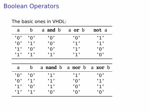
Boolean Operators
The basic ones in VHDL:
a b a and b a or b not a
’0’ ’0’ ’0’ ’0’ ’1’’0’ ’1’ ’0’ ’1’ ’1’’1’ ’0’ ’0’ ’1’ ’0’’1’ ’1’ ’1’ ’1’ ’0’
a b a nand b a nor b a xor b
’0’ ’0’ ’1’ ’1’ ’0’’0’ ’1’ ’1’ ’0’ ’1’’1’ ’0’ ’1’ ’0’ ’1’’1’ ’1’ ’0’ ’0’ ’0’

Rules of Boolean Algebra (1)
-- Precedencenot a or b and c = (not a) or (b and c)
-- Basic relationshipsnot not a = aa and ’1’ = aa and ’0’ = ’0’a or ’1’ = ’1’a or ’0’ = aa and a = aa and not a = ’0’a or a = aa or not a = ’1’a nand b = not (a and b)a nor b = not (a or b)a xor ’0’ = aa xor ’1’ = not aa xor b = (not a and b) or (a and not b)
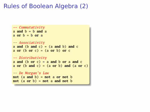
Rules of Boolean Algebra (2)
-- Commutativitya and b = b and aa or b = b or a
-- Associativitya and (b and c) = (a and b) and ca or (b or c) = (a or b) or c
-- Distributivitya and (b or c) = a and b or a and ca or (b and c) = (a or b) and (a or c)
-- De Morgan’s Lawnot (a and b) = not a or not bnot (a or b) = not a and not b
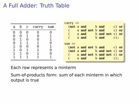
A Full Adder: Truth Table
a b c carry sum
0 0 0 0 00 0 1 0 10 1 0 0 10 1 1 1 01 0 0 0 11 0 1 1 01 1 0 1 01 1 1 1 1
carry <=(not a and b and c) or( a and not b and c) or( a and b and not c) or( a and b and c);
sum <=(not a and not b and c) or(not a and b and not c) or( a and not b and not c) or( a and b and c);
Each row represents a minterm
Sum-of-products form: sum of each minterm in whichoutput is true

Simplifying Using Boolean Rules
carry <= (not a and b and c) or (a and not b and c) or(a and b and not c) or (a and b and c);
<= (a and b and not c) or (a and b and c) or(not a and b and c) or (a and b and c) or(a and not b and c) or (a and b and c);
<= (a and b) or (b and c) or (a and c);
sum <= (not a and not b and c) or (not a and b and not c) or(a and not b and not c) or (a and b and c);
<= (not a) and ((not b and c) or (b and not c)) ora and ((not b and not c) or (b and c));
<= a xor b xor c;

Structure of a VHDL Module
in
PORTS
in
out
out
inout
process (clk)begin
if rising_edge(clk) thencount <= count + 1;
end if;end process;
PROCESS
SIGNAL
X <= ’1’ when Y = ’1’ and X = "110"else ’0’DATAFLOW EXPRESSION
COMPONENT

A Full Adder in VHDLlibrary ieee; -- always neededuse ieee.std_logic_1164.all; -- std_logic, et al.
entity full_adder is -- the interfaceport(a, b, c : in std_logic;
sum, carry : out std_logic);end full_adder;
architecture imp of full_adder is -- the implementationbegin
sum <= (a xor b) xor c; -- combinational logiccarry <= (a and b) or (a and c) or (b and c);
end imp;
sum
carry
cba
sum
carry
cab

...After Logic Synthesis
sum~1
carry~0
carry~1
carry~4a
bc
sum
carry
carry~3
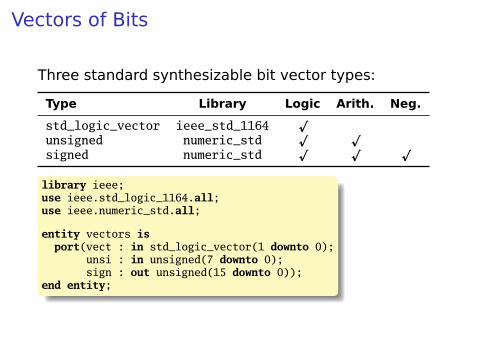
Vectors of Bits
Three standard synthesizable bit vector types:
Type Library Logic Arith. Neg.
std_logic_vector ieee_std_1164p
unsigned numeric_stdp p
signed numeric_stdp p p
library ieee;use ieee.std_logic_1164.all;use ieee.numeric_std.all;
entity vectors isport(vect : in std_logic_vector(1 downto 0);
unsi : in unsigned(7 downto 0);sign : out unsigned(15 downto 0));
end entity;
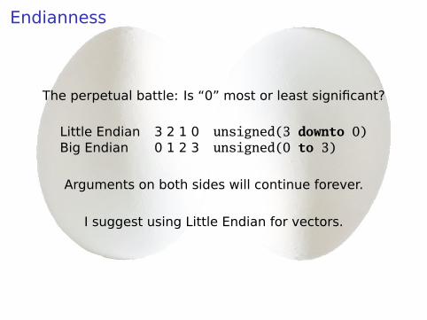
Endianness
The perpetual battle: Is “0” most or least significant?
Little Endian 3 2 1 0 unsigned(3 downto 0)Big Endian 0 1 2 3 unsigned(0 to 3)
Arguments on both sides will continue forever.
I suggest using Little Endian for vectors.

Binary and Hexadecimal in VHDL
Dec. Binary Hex
0 "0" x"0"1 "1" x"1"2 "10" x"2"3 "11" x"3"4 "100" x"4"5 "101" x"5"6 "110" x"6"7 "111" x"7"8 "1000" x"8"9 "1001" x"9"
10 "1010" x"A"11 "1011" x"B"12 "1100" x"C"13 "1101" x"D"14 "1110" x"E"15 "1111" x"F"16 "10000" x"10"17 "10001" x"11"18 "10010" x"12"19 "10011" x"13"
Vector types are arrays ofstd_logic
Literals are therefore strings of 0’sand 1’s-- from std_logic_1164type std_logic_vector is
array (natural range <>) of std_logic;
--- from numeric_stdtype unsigned is
array (natural range <>) of std_logic;
type signed isarray (natural range <>) of std_logic;
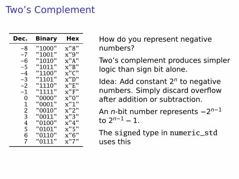
Two’s Complement
Dec. Binary Hex
-8 "1000" x"8"-7 "1001" x"9"-6 "1010" x"A"-5 "1011" x"B"-4 "1100" x"C"-3 "1101" x"D"-2 "1110" x"E"-1 "1111" x"F"0 "0000" x"0"1 "0001" x"1"2 "0010" x"2"3 "0011" x"3"4 "0100" x"4"5 "0101" x"5"6 "0110" x"6"7 "0111" x"7"
How do you represent negativenumbers?
Two’s complement produces simplerlogic than sign bit alone.
Idea: Add constant 2n to negativenumbers. Simply discard overflowafter addition or subtraction.
An n-bit number represents −2n−1
to 2n−1 − 1.
The signed type in numeric_stduses this

A Hex-to-seven-segment Decoder
a
b
c
d
e
f
g
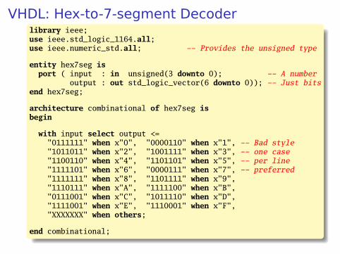
VHDL: Hex-to-7-segment Decoderlibrary ieee;use ieee.std_logic_1164.all;use ieee.numeric_std.all; -- Provides the unsigned type
entity hex7seg isport ( input : in unsigned(3 downto 0); -- A number
output : out std_logic_vector(6 downto 0)); -- Just bitsend hex7seg;
architecture combinational of hex7seg isbegin
with input select output <="0111111" when x"0", "0000110" when x"1", -- Bad style"1011011" when x"2", "1001111" when x"3", -- one case"1100110" when x"4", "1101101" when x"5", -- per line"1111101" when x"6", "0000111" when x"7", -- preferred"1111111" when x"8", "1101111" when x"9","1110111" when x"A", "1111100" when x"B","0111001" when x"C", "1011110" when x"D","1111001" when x"E", "1110001" when x"F","XXXXXXX" when others;
end combinational;
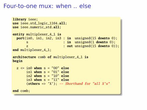
Four-to-one mux: when .. else
library ieee;use ieee.std_logic_1164.all;use ieee.numeric_std.all;
entity multiplexer_4_1 isport(in0, in1, in2, in3 : in unsigned(15 downto 0);
s : in unsigned(1 downto 0);z : out unsigned(15 downto 0));
end multiplexer_4_1;
architecture comb of multiplexer_4_1 isbegin
z <= in0 when s = "00" elsein1 when s = "01" elsein2 when s = "10" elsein3 when s = "11" else(others => ’X’); -- Shorthand for "all X’s"
end comb;
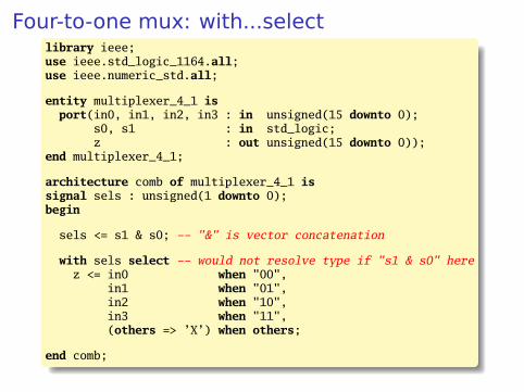
Four-to-one mux: with...selectlibrary ieee;use ieee.std_logic_1164.all;use ieee.numeric_std.all;
entity multiplexer_4_1 isport(in0, in1, in2, in3 : in unsigned(15 downto 0);
s0, s1 : in std_logic;z : out unsigned(15 downto 0));
end multiplexer_4_1;
architecture comb of multiplexer_4_1 issignal sels : unsigned(1 downto 0);begin
sels <= s1 & s0; -- "&" is vector concatenation
with sels select -- would not resolve type if "s1 & s0" herez <= in0 when "00",
in1 when "01",in2 when "10",in3 when "11",(others => ’X’) when others;
end comb;

Three-to-eight Decoder
library ieee;use ieee.std_logic_1164.all;use ieee.numeric_std.all;
entity dec1_8 isport (
sel : in unsigned(2 downto 0);res : out unsigned(7 downto 0));
end dec1_8;
architecture comb of dec1_8 isbegin
res <= "00000001" when sel = "000" else"00000010" when sel = "001" else"00000100" when sel = "010" else"00001000" when sel = "011" else"00010000" when sel = "100" else"00100000" when sel = "101" else"01000000" when sel = "110" else"10000000";
end comb;
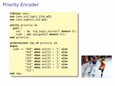
Priority Encoder
library ieee;use ieee.std_logic_1164.all;use ieee.numeric_std.all;
entity priority isport (
sel : in std_logic_vector(7 downto 0);code : out unsigned(2 downto 0));
end priority;
architecture imp of priority isbegin
code <= "000" when sel(0) = ’1’ else"001" when sel(1) = ’1’ else"010" when sel(2) = ’1’ else"011" when sel(3) = ’1’ else"100" when sel(4) = ’1’ else"101" when sel(5) = ’1’ else"110" when sel(6) = ’1’ else"111";
end imp;
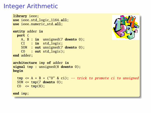
Integer Arithmeticlibrary ieee;use ieee.std_logic_1164.all;use ieee.numeric_std.all;
entity adder isport (
A, B : in unsigned(7 downto 0);CI : in std_logic;SUM : out unsigned(7 downto 0);CO : out std_logic);
end adder;
architecture imp of adder issignal tmp : unsigned(8 downto 0);begin
tmp <= A + B + ("0" & ci); -- trick to promote ci to unsignedSUM <= tmp(7 downto 0);CO <= tmp(8);
end imp;

A Very Simple ALU
library ieee;use ieee.std_logic_1164.all;use ieee.numeric_std.all;
entity alu isport (
A, B : in unsigned(7 downto 0);ADD : in std_logic;RES : out unsigned(7 downto 0));
end alu;
architecture imp of alu isbegin
RES <= A + B when ADD = ’1’ elseA - B;
end imp;
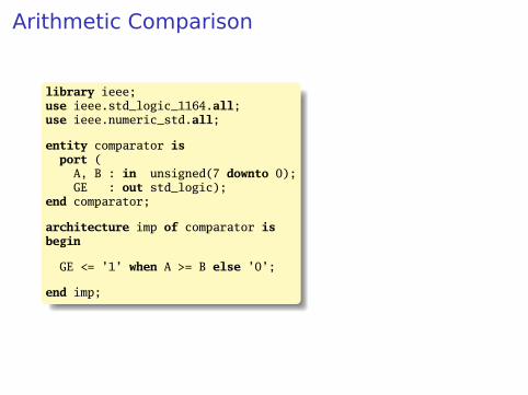
Arithmetic Comparison
library ieee;use ieee.std_logic_1164.all;use ieee.numeric_std.all;
entity comparator isport (
A, B : in unsigned(7 downto 0);GE : out std_logic);
end comparator;
architecture imp of comparator isbegin
GE <= ’1’ when A >= B else ’0’;
end imp;

Tri-state drivers
How to use a pin as both an input and output.Not for internal FPGA signals.library ieee;use ieee.std_logic_1164.all;use ieee.numeric_std.all;
entity tri_demo isport(addr : out unsigned(15 downto 0); -- output only
data : inout unsigned(7 downto 0)); -- bidirectionalend tri_demo;
architecture rtl of tri_demo is
signal oe : std_logic; -- output enable: control direction of datasignal d_out : unsigned(7 downto 0);
begin
data <= d_out when oe = ’1’ else -- Drive data to chip(others => ’Z’); -- Read data from external chip
end rtl;
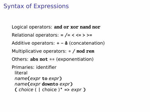
Syntax of Expressions
Logical operators: and or xor nand nor
Relational operators: = /= < <= > >=
Additive operators: + - & (concatenation)
Multiplicative operators: * / mod rem
Others: abs not ** (exponentiation)
Primaries: identifierliteralname(expr to expr)name(expr downto expr)( choice ( | choice )∗ => expr )

Summary of Dataflow Modeling
É Conditional signal assignment (when...else)
target <= (expr when expr else)∗
expr ;
É Selected signal assignment (with...select)
with expr selecttarget <= (expr when choice (| choice)∗,)∗
expr when choice (| choice)∗ ;
A choice is a simple expression (i.e., not logical orcomparison) or others.
Note: when does not nest (i.e., it’s not an expr).

Hierarchy: Instantiating Components(entities)
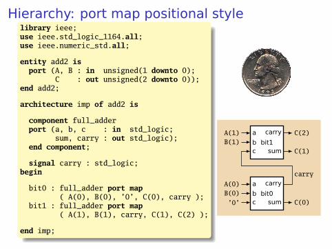
Hierarchy: port map positional stylelibrary ieee;use ieee.std_logic_1164.all;use ieee.numeric_std.all;
entity add2 isport (A, B : in unsigned(1 downto 0);
C : out unsigned(2 downto 0));end add2;
architecture imp of add2 is
component full_adderport (a, b, c : in std_logic;
sum, carry : out std_logic);end component;
signal carry : std_logic;begin
bit0 : full_adder port map( A(0), B(0), ’0’, C(0), carry );
bit1 : full_adder port map( A(1), B(1), carry, C(1), C(2) );
end imp;
bit1
bit0c’0’bB(0)aA(0)
sum C(0)
carrycarry
cbB(1)aA(1)
sum C(1)
carry C(2)

Hierarchy: port map by-name stylelibrary ieee;use ieee.std_logic_1164.all;use ieee.numeric_std.all;
entity add2n isport (A, B : in unsigned(1 downto 0);
C : out unsigned(2 downto 0));end add2n;
architecture imp of add2n is
component full_adderport (a, b, c : in std_logic;
sum, carry : out std_logic);end component;signal carry : std_logic;
begin
bit0 : full_adder port map (a => A(0), b => B(0), c => ’0’,sum => C(0), carry => carry);
bit1 : full_adder port map (a => A(1), b => B(1), c => carry,sum => C(1), carry => C(2));
end imp;

Direct Instantiation (no component)
library ieee;use ieee.std_logic_1164.all;use ieee.numeric_std.all;
entity add2 isport (A, B : in unsigned(1 downto 0);
C : out unsigned(2 downto 0));end add2;
architecture imp of add2 issignal carry : std_logic;
begin
bit0 : entity work.full_adder -- everything in "work" projectport map ( A(0), B(0), ’0’, C(0), carry );
bit1 : entity work.full_adderport map ( A(1), B(1), carry, C(1), C(2) );
end imp;
Must be compiled after full_adder.vhd!

Generate: Ripple-carry adderlibrary ieee;use ieee.std_logic_1164.all;use ieee.numeric_std.all;
entity rippleadder isport (a, b : in unsigned(3 downto 0);
cin : in std_logic;sum : out unsigned(3 downto 0);cout : out std_logic);
end rippleadder;
architecture imp of rippleadder issignal c : unsigned(4 downto 0);
beginc(0) <= cin;
G1: for m in 0 to 3 generate -- expanded at compile timesum(m) <= a(m) xor b(m) xor c(m);c(m+1) <= (a(m) and b(m)) or (b(m) and c(m)) or
(a(m) and c(m));end generate G1;
cout <= c(4);end imp;

Combinational Logic in a Procedural Style
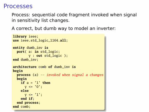
ProcessesProcess: sequential code fragment invoked when signalin sensitivity list changes.
A correct, but dumb way to model an inverter:
library ieee;use ieee.std_logic_1164.all;
entity dumb_inv isport( a: in std_logic;
y : out std_logic );end dumb_inv;
architecture comb of dumb_inv isbegin
process (a) -- invoked when signal a changesbegin
if a = ’1’ theny <= ’0’;
elsey <= ’1’;
end if;end process;
end comb;

A 4-to-1 mux in the procedural stylelibrary ieee;use ieee.std_logic_1164.all;use ieee.numeric_std.all;
entity pmultiplexer_4_1 isport(in0, in1, in2, in3 : in unsigned(15 downto 0);
s : in unsigned(1 downto 0);z : out unsigned(15 downto 0));
end pmultiplexer_4_1;
architecture comb of pmultiplexer_4_1 isbegin
process (in0, in1, in2, in3, s)begin
z <= (others => ’X’); -- defaultif s = "00" then z <= in0; -- assignment overrides defaultelsif s = "01" then z <= in1;elsif s = "10" then z <= in2;elsif s = "11" then z <= in3;end if;
end process;
end comb;
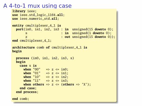
A 4-to-1 mux using caselibrary ieee;use ieee.std_logic_1164.all;use ieee.numeric_std.all;
entity cmultiplexer_4_1 isport(in0, in1, in2, in3 : in unsigned(15 downto 0);
s : in unsigned(1 downto 0);z : out unsigned(15 downto 0));
end cmultiplexer_4_1;
architecture comb of cmultiplexer_4_1 isbegin
process (in0, in1, in2, in3, s)begin
case s iswhen "00" => z <= in0;when "01" => z <= in1;when "10" => z <= in2;when "11" => z <= in3;when others => z <= (others => ’X’);
end case;end process;
end comb;
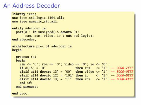
An Address Decoderlibrary ieee;use ieee.std_logic_1164.all;use ieee.numeric_std.all;
entity adecoder isport(a : in unsigned(15 downto 0);
ram, rom, video, io : out std_logic);end adecoder;
architecture proc of adecoder isbegin
process (a)begin
ram <= ’0’; rom <= ’0’; video <= ’0’; io <= ’0’;if a(15) = ’0’ then ram <= ’1’; -- 0000-7FFFelsif a(14 downto 13) = "00" then video <= ’1’; -- 8000-9FFFelsif a(14 downto 12) = "101" then io <= ’1’; -- D000-DFFFelsif a(14 downto 13) = "11" then rom <= ’1’; -- E000-FFFFend if;
end process;
end proc;

Summary of Procedural Modeling
null
signal <= expr ;
variable := expr ;
if expr then stmts(elsif expr then stmts)∗
(else stmts)?end if;
case expr is(when choices => stmts)∗
end case;
Note: when...else and with...select not allowed
Sequential Logic

Basic D Flip-Flop
library ieee;use ieee.std_logic_1164.all;
entity flipflop isport (Clk, D : in std_logic;
Q : out std_logic);end flipflop;
architecture imp of flipflop isbegin
process (Clk) -- Sensitive only to Clkbegin
if rising_edge(Clk) then -- 0->1 transitionQ <= D;
end if;end process;
end imp;
D Q

Flip-Flop with Latch Enable
library ieee;use ieee.std_logic_1164.all;
entity flipflop_enable isport (Clk, D, EN : in std_logic;
Q : out std_logic);end flipflop_enable;
architecture imp of flipflop_enable isbegin
process (Clk)beginif rising_edge(Clk) thenif EN = ’1’ then
Q <= D;end if;
end if;end process;
end imp;
D Q Q01D
Clk
EN

Flip-Flop with Synchronous Resetlibrary ieee;use ieee.std_logic_1164.all;
entity flipflop_reset isport (Clk, Reset, D : in std_logic;
Q : out std_logic);end flipflop_reset;
architecture imp of flipflop_reset isbegin
process (Clk)begin
if rising_edge(Clk) thenif Reset = ’1’ thenQ <= ’0’;
elseQ <= D;
end if;end if;
end process;
end imp;

Four-bit binary counterlibrary ieee;use ieee.std_logic_1164.all;use ieee.numeric_std.all;
entity counter isport(Clk, Reset : in std_logic;
Q : out unsigned(3 downto 0));end counter;
architecture imp of counter issignal count : unsigned(3 downto 0);begin
process (Clk)begin
if rising_edge(Clk) thenif Reset = ’1’ then count <= (others => ’0’);else count <= count + 1;end if;
end if;end process;
Q <= count; -- copy count to output
end imp;
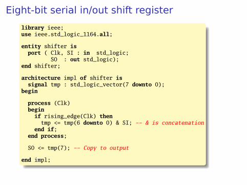
Eight-bit serial in/out shift register
library ieee;use ieee.std_logic_1164.all;
entity shifter isport ( Clk, SI : in std_logic;
SO : out std_logic);end shifter;
architecture impl of shifter issignal tmp : std_logic_vector(7 downto 0);
begin
process (Clk)begin
if rising_edge(Clk) thentmp <= tmp(6 downto 0) & SI; -- & is concatenation
end if;end process;
SO <= tmp(7); -- Copy to output
end impl;
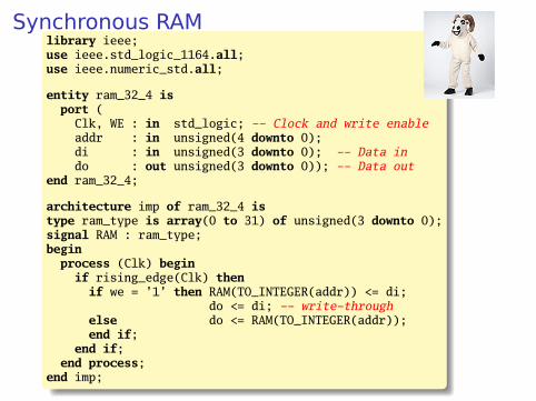
Synchronous RAMlibrary ieee;use ieee.std_logic_1164.all;use ieee.numeric_std.all;
entity ram_32_4 isport (
Clk, WE : in std_logic; -- Clock and write enableaddr : in unsigned(4 downto 0);di : in unsigned(3 downto 0); -- Data indo : out unsigned(3 downto 0)); -- Data out
end ram_32_4;
architecture imp of ram_32_4 istype ram_type is array(0 to 31) of unsigned(3 downto 0);signal RAM : ram_type;begin
process (Clk) beginif rising_edge(Clk) thenif we = ’1’ then RAM(TO_INTEGER(addr)) <= di;
do <= di; -- write-throughelse do <= RAM(TO_INTEGER(addr));end if;
end if;end process;
end imp;
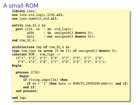
A small ROMlibrary ieee;use ieee.std_logic_1164.all;use ieee.numeric_std.all;
entity rom_32_4 isport (Clk, en : in std_logic;
addr : in unsigned(3 downto 0);data : out unsigned(3 downto 0));
end rom_32_4;
architecture imp of rom_32_4 istype rom_type is array (0 to 15) of unsigned(3 downto 0);constant ROM : rom_type :=
(X"1", X"2", X"3", X"4", X"5", X"6", X"7", X"8",X"9", X"A", X"B", X"C", X"D", X"E", X"F", X"1");
begin
process (Clk)begin
if rising_edge(Clk) thenif en = ’1’ then data <= ROM(TO_INTEGER(addr)); end if;
end if;end process;
end imp;
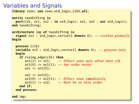
Variables and Signalslibrary ieee; use ieee.std_logic_1164.all;
entity twoshiftreg isport(clk, si1, si2 : in std_logic; so1, so2 : out std_logic);
end twoshiftreg;
architecture imp of twoshiftreg issignal sr1 : std_logic_vector(1 downto 0); -- visible globally
begin
process (clk)variable sr2 : std_logic_vector(1 downto 0); -- process-onlybegin
if rising_edge(clk) thensr1(1) <= si1; -- Effect seen only after next clksr1(0) <= sr1(1); -- Any order worksso1 <= sr1(0);
so2 <= sr2(0);sr2(0) := sr2(1); -- Effect seen immediatelysr2(1) := si2; -- Must be in this order
end if;end process;
end imp;

Variables vs. Signals
Property Variables Signals
Scope Local to process Visible throughoutarchitecture
Assignment Felt immediately(e.g., in nextstatement)
Only visible after clockrises (i.e., processterminates)
Lesson: use variables to hold temporary results andstate to be hidden within a process. Otherwise, usesignals.
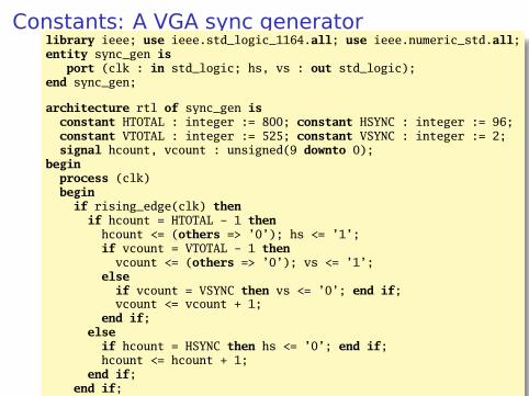
Constants: A VGA sync generatorlibrary ieee; use ieee.std_logic_1164.all; use ieee.numeric_std.all;entity sync_gen is
port (clk : in std_logic; hs, vs : out std_logic);end sync_gen;
architecture rtl of sync_gen isconstant HTOTAL : integer := 800; constant HSYNC : integer := 96;constant VTOTAL : integer := 525; constant VSYNC : integer := 2;signal hcount, vcount : unsigned(9 downto 0);
beginprocess (clk)begin
if rising_edge(clk) thenif hcount = HTOTAL - 1 thenhcount <= (others => ’0’); hs <= ’1’;if vcount = VTOTAL - 1 thenvcount <= (others => ’0’); vs <= ’1’;
elseif vcount = VSYNC then vs <= ’0’; end if;vcount <= vcount + 1;
end if;elseif hcount = HSYNC then hs <= ’0’; end if;hcount <= hcount + 1;
end if;end if;
end process;end rtl;

FSMs

Moore and Mealy Machines
Next StateLogic
Output Logic
CLK
NextState
CurrentState
Inputs Outputs
The Moore Form:
Outputs are a function of only the current state.
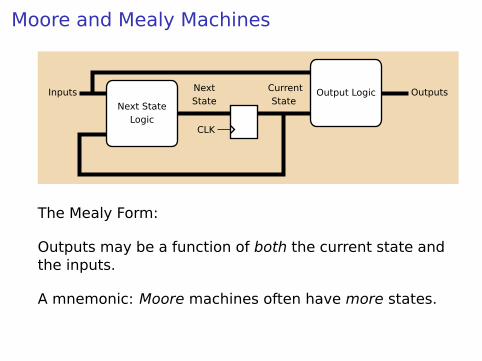
Moore and Mealy Machines
Next StateLogic
Output Logic
CLK
NextState
CurrentState
Inputs Outputs
The Mealy Form:
Outputs may be a function of both the current state andthe inputs.
A mnemonic: Moore machines often have more states.
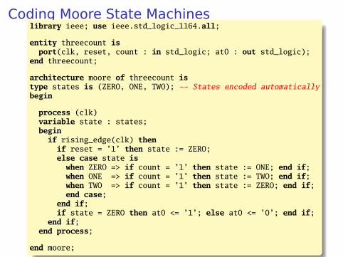
Coding Moore State Machineslibrary ieee; use ieee.std_logic_1164.all;
entity threecount isport(clk, reset, count : in std_logic; at0 : out std_logic);
end threecount;
architecture moore of threecount istype states is (ZERO, ONE, TWO); -- States encoded automaticallybegin
process (clk)variable state : states;begin
if rising_edge(clk) thenif reset = ’1’ then state := ZERO;else case state is
when ZERO => if count = ’1’ then state := ONE; end if;when ONE => if count = ’1’ then state := TWO; end if;when TWO => if count = ’1’ then state := ZERO; end if;end case;
end if;if state = ZERO then at0 <= ’1’; else at0 <= ’0’; end if;
end if;end process;
end moore;
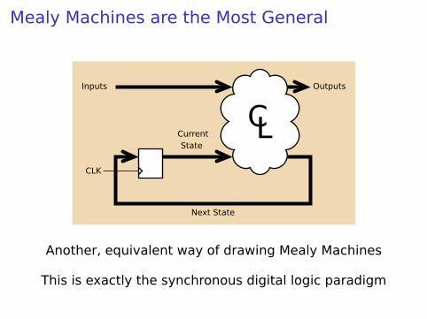
Mealy Machines are the Most General
CLCurrentState
Next State
Inputs Outputs
CLK
Another, equivalent way of drawing Mealy Machines
This is exactly the synchronous digital logic paradigm

Coding Mealy State Machines
architecture mealy of ... istype states is (IDLE, STATE1, ...);signal state, next_state : states;beginprocess (clk) -- Sequential processbegin
if rising_edge(clk) then state <= next_state; end if;end process;
process (reset, state, i1, i2, ... ) -- Combinational processbegin
next_state <= state; -- Default: holdif reset = ’1’ then
next_state <= IDLE;else
case state iswhen IDLE =>if i1 = ’1’ then
next_state <= STATE1;end if;
when STATE1 =>
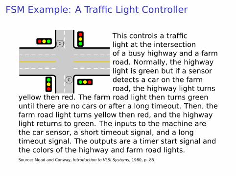
FSM Example: A Traffic Light Controller
C
C
This controls a trafficlight at the intersectionof a busy highway and a farmroad. Normally, the highwaylight is green but if a sensordetects a car on the farmroad, the highway light turns
yellow then red. The farm road light then turns greenuntil there are no cars or after a long timeout. Then, thefarm road light turns yellow then red, and the highwaylight returns to green. The inputs to the machine arethe car sensor, a short timeout signal, and a longtimeout signal. The outputs are a timer start signal andthe colors of the highway and farm road lights.Source: Mead and Conway, Introduction to VLSI Systems, 1980, p. 85.

State Transition Diagram for the TLC
HGH : GF : R
HYH : YF : R
C+ L/TCL/T
FGH : RF : G
FYH : RF : Y
S/T
S/T
CL/TC+ L/T
S/T
S/T
Inputs:C: Car sensorS: Short TimeoutL: Long Timeout
Outputs:T: Timer ResetH: Highway colorF: Farm road color

State Transition Diagram for the TLC
HGH : GF : R
HYH : YF : R
C+ L/TCL/T
FGH : RF : G
FYH : RF : Y
S/T
S/T
CL/TC+ L/T
S/T
S/T
Inputs:C: Car sensorS: Short TimeoutL: Long Timeout
Outputs:T: Timer ResetH: Highway colorF: Farm road color

State Transition Diagram for the TLC
HGH : GF : R
HYH : YF : R
C+ L/TCL/T
FGH : RF : G
FYH : RF : Y
S/T
S/T
CL/TC+ L/T
S/T
S/T
Inputs:C: Car sensorS: Short TimeoutL: Long Timeout
Outputs:T: Timer ResetH: Highway colorF: Farm road color

Traffic Light Controller in VHDL
library ieee;use ieee.std_logic_1164.all;entity tlc isport (clk, reset : in std_logic;
cars, short, long : in std_logic;highway_yellow, highway_red : out std_logic;farm_yellow, farm_red : out std_logic;start_timer : out std_logic);
end tlc;
architecture imp of tlc istype states is (HG, HY, FY, FG);signal state, next_state : states;begin
process (clk) -- Sequential processbegin
if rising_edge(clk) thenstate <= next_state;
end if;end process;

TLC in VHDL, continued
process (state, reset, cars, short, long)beginif reset = ’1’ then
start_timer <= ’1’; next_state <= HG;else
case state iswhen HG =>
highway_yellow <= ’0’; highway_red <= ’0’;farm_yellow <= ’0’; farm_red <= ’1’;if cars = ’1’ and long = ’1’ then
start_timer <= ’1’; next_state <= HY;else start_timer <= ’0’; next_state <= HG;end if;
when HY =>highway_yellow <= ’1’; highway_red <= ’0’;farm_yellow <= ’0’; farm_red <= ’1’;if short = ’1’ then
start_timer <= ’1’; next_state <= FG;else start_timer <= ’0’; next_state <= HY;end if;

TLC in VHDL, concluded
when FG =>highway_yellow <= ’0’; highway_red <= ’1’;farm_yellow <= ’0’; farm_red <= ’0’;if cars = ’0’ or long = ’1’ then
start_timer <= ’1’; next_state <= FY;else start_timer <= ’0’; next_state <= FG;end if;
when FY =>highway_yellow <= ’0’; highway_red <= ’1’;farm_yellow <= ’1’; farm_red <= ’0’;if short = ’1’ then
start_timer <= ’1’; next_state <= HG;else start_timer <= ’0’; next_state <= FY;end if;
end case;end if;
end process;
end imp;
Summary of the Three Modeling Styles
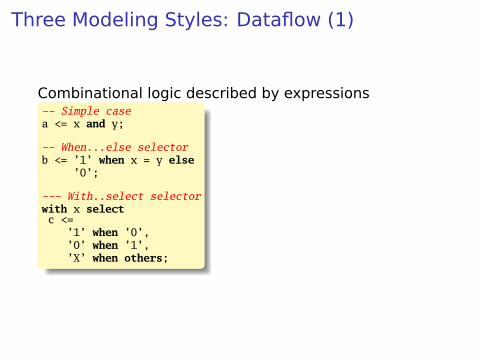
Three Modeling Styles: Dataflow (1)
Combinational logic described by expressions-- Simple casea <= x and y;
-- When...else selectorb <= ’1’ when x = y else
’0’;
--- With..select selectorwith x selectc <=
’1’ when ’0’,’0’ when ’1’,’X’ when others;

Procedural Combinational (2)
Combinational logic described by statements andexpressionsprocess (x, y) -- Should be sensitive to every signal it readsbegin
a <= x and y;if x = y then
b <= ’1’;else
b <= ’0’;end if;case x of
’0’ => c <= ’1’;’1’ => c <= ’0’;others => c <= ’X’;
end case;end process;

Three Styles: Procedural Sequential (3)
Combinational logic driving flip-flops described bystatements and expressions.process (clk) -- Sensitive only to the clockbegin
if rising_edge(clk) then -- Always check for rising edgea <= x and y;if x = y then
b <= ’1’;else
b <= ’0’;end if;case x of
’0’ => c <= ’1’;’1’ => c <= ’0’;others => c <= ’X’;
end case;end if;
end process;

Ten Commandments of VHDL
www.catholicsupply.com

I: Thou Shalt Design Before Coding
É Know the structure of what you are designing first.É Draw a block diagram of the datapathÉ Understand the timing (draw diagrams)É Draw bubble-and-arc diagrams for FSMsÉ Only once you have a design should you start
coding in VHDLÉ VHDL is only a way to ask for component

II: Thou Shalt be Synchronous
É One global clockÉ Flip-flops generate inputs to combinational logic,
which computes inputs to flip-flopsÉ Exactly one value per signal per clock cycleÉ Do not generate asynchronous reset signals; only
use them if they are externalÉ Edge-triggered flip-flops only. Do not use
level-sensitive logic.É Do not generate clock signals. Use multiplexers to
create “load enable” signals on flip-flops.
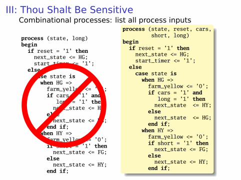
III: Thou Shalt Be SensitiveCombinational processes: list all process inputs
process (state, long)begin
if reset = ’1’ thennext_state <= HG;start_timer <= ’1’;
elsecase state iswhen HG =>
farm_yellow <= ’0’;if cars = ’1’ and
long = ’1’ thennext_state <= HY;
elsenext_state <= HG;
end if;when HY =>farm_yellow <= ’0’;if short = ’1’ then
next_state <= FG;else
next_state <= HY;end if;
process (state, reset, cars,short, long)
beginif reset = ’1’ then
next_state <= HG;start_timer <= ’1’;
elsecase state iswhen HG =>
farm_yellow <= ’0’;if cars = ’1’ and
long = ’1’ thennext_state <= HY;
elsenext_state <= HG;
end if;when HY =>
farm_yellow <= ’0’;if short = ’1’ thennext_state <= FG;
elsenext_state <= HY;
end if;

III: Thou Shalt Be Sensitive
Sequential processes: always include the clock. Includereset if asynchronous, and nothing else.process (Clk, D)begin
if rising_edge(Clk) thenQ <= D;
end if;end process;
process (Clk, D)begin
if reset = ’1’ thenQ <= ’0’;
elseif rising_edge(Clk) then
Q <= D;end if;
end if;end process;
process (Clk)beginif rising_edge(Clk) then
Q <= D;end if;
end process;
process (Clk, reset)beginif reset = ’1’ then
Q <= ’0’;else
if rising_edge(Clk) thenQ <= D;
end if;end if;
end process;

IV: Thou Shalt Assign All Outputs
Synthesis infers level-sensitive latches if sometimesyou do not assign an output.
process (state, input)begin
case state iswhen S1 =>
if input = ’1’ thenoutput <= ’0’;
end if;when S2 =>
output <= ’1’;end case;
end process;
process (state, input)begincase state is
when S1 =>if input = ’1’ thenoutput <= ’0’;
elseoutput <= ’1’;
end if;when S2 =>
output <= ’1’;end case;
end process;

“Default” values are convenient
-- OK
process (state, input)begincase state is
when S1 =>if input = ’1’ then
output <= ’0’;else
output <= ’1’;end if;
when S2 =>output <= ’1’;
end case;end process;
-- Better
process (state, input)beginoutput <= ’1’;case state is
when S1 =>if input = ’1’ thenoutput <= ’0’;
end if;end case;
end process;

V: Thou Shalt Enumerate StatesBetter to use an enumeration to encode states:type states is (START, RUN, IDLE, ZAPHOD);signal current, next : states;
process (current)begin
case current iswhen START => ...when RUN => ...when IDLE => ...
end case;end process;
Running this produces a helpful error:
Compiling vhdl file "/home/cristi/cs4840/lab4/main.vhd" in Library work.Entity <system> compiled.ERROR:HDLParsers:813 - "/home/cristi/cs4840/lab4/main.vhd" Line 80.Enumerated value zaphod is missing in case.-->

VI:
(There is no rule six)

VII: Thou Shalt Avoid Async
Only use asynchronous reset when there is one globalsignal from outside.-- OK for external Resetprocess (Clk, Reset)beginif Reset = ’1’ then
Q <= ’0’;else
if rising_edge(Clk) thenQ <= D;
end if;end if;
end process;
-- Betterprocess (Clk)beginif rising_edge(Clk) then
if Reset = ’1’ thenQ <= ’0’;
elseQ <= D;
end if;end if;
end process;
Never generate your own asynchronous reset.Generating a synchronous reset is fine

VIII: Thou Shalt Have One Version
É Never assume signals from the test bench that arenot there on the board
É It is hard enough to make simulation match thedesign; do not make it any harder
É If you must slow down hardware, carefully generatea slower clock and only use that clock globally.

IX: Thou Shalt Not Test For X Or Z
architecture behv of ALU isbegin
process (A,B,Sel) begincase Sel is
when "00" =>Res <= A + B;
when "01" =>Res <= A + (not B) + 1;
when "1X" =>Res <= A and B;
when "1Z" =>Res <= A or B;
when others =>Res <= "XX";
end case;end process;
end behv;
architecture behv of ALU isbeginprocess(A,B,Sel) begin
case Sel iswhen "00" =>
Res <= A + B;when "01" =>
Res <= A + (not B) + 1;when "10" =>
Res <= A and B;when "11" =>
Res <= A or B;when others =>
Res <= "XX";end case;
end process;end behv;
This is legal VHDL, but the synthesized circuit won’tbehave like you expect.

X: Thou Shalt Not Specify Delays
É The wait statement can delay for a certain amountof time, e.g., “wait 10ns;”
É Only use it in test benches that are not meant tobecome hardware
É Do not use them in the design of your hardware

Pitfalls: Boolean vs. Std_logic
Don’t assign Boolean to std_logic.signal a : std_logic;signal b : unsigned(7 downto 0);
a <= b = x"7E"; -- BAD: result is Boolean, not std_logic
a <= ’1’ when b = x"7E" else ’0’; -- OK
Don’t test std_logic in a Boolean context.signal a, b, foo : std_logic;
if a then -- BAD: A is not Booleanfoo <= ’1’;
end if;b <= ’0’ when a else ’1’; -- BAD: a is not Boolean
if a = ’1’ then -- OKfoo <= ’1’;
end if;b <= ’0’ when a = ’1’ else ’0’; -- OK
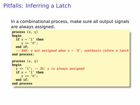
Pitfalls: Inferring a Latch
In a combinational process, make sure all output signalsare always assigned.process (x, y)beginif x = ’1’ then
y <= ’0’;end if;-- BAD: y not assigned when x = ’0’, synthesis infers a latch
end process;
process (x, y)beginy <= ’1’; -- OK: y is always assignedif x = ’1’ then
y <= ’0’;end if;
end process
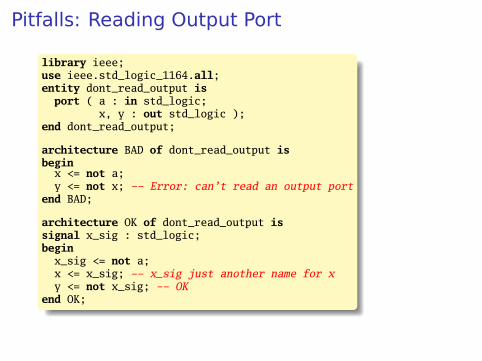
Pitfalls: Reading Output Port
library ieee;use ieee.std_logic_1164.all;entity dont_read_output isport ( a : in std_logic;
x, y : out std_logic );end dont_read_output;
architecture BAD of dont_read_output isbegin
x <= not a;y <= not x; -- Error: can’t read an output port
end BAD;
architecture OK of dont_read_output issignal x_sig : std_logic;begin
x_sig <= not a;x <= x_sig; -- x_sig just another name for xy <= not x_sig; -- OK
end OK;

Pitfalls: Complex Port Map Args
library ieee;use ieee.std_logic_1164.all;use ieee.numeric_std.all;entity bad_port_map is end bad_port_map;
architecture BAD of bad_port_map iscomponent bar port (x : in unsigned(5 downto 0) ); end component;signal a : unsigned(3 downto 0);begin
mybar : bar port map ( x => "000" & a); -- BADend BAD;
architecture OK of bad_port_map iscomponent bar port (x : in unsigned(5 downto 0) ); end component;signal a : unsigned(3 downto 0);signal aa : unsigned(5 downto 0);begin
aa <= "000" & a;mybar : bar port map ( x => aa ); -- OK
end OK;
Pitfalls: Combinational Loops
You never really need them.
Drive every signal from exactly one process orconcurrent assignment.
Don’t build SR latches. Use D flip-flops instead.
Pitfalls: Clock Gating
Dangerous, difficult to get right.
Use a single, global clock and latch enables to performthe same function.

Pitfalls: Multiple Clock Domains
If you must, vary the phase and drive clocks directlyfrom flip-flops.

Writing Testbenches

Testbenches
One of VHDL’s key points: can describe hardware andenvironment together.-- Explicit delays are allowedclk <= not clk after 50 ns;
processbegin
reset <= ’0’;wait for 10 ns; -- Explicit delayreset <= ’1’;wait for a = ’1’; -- Delay for an eventassert b = ’1’ report "b did not rise" severity failure;assert c = ’1’ report "c=0" severity warning; -- or error or notewait for 50 ns; -- Delay for some timewait; -- Halt this process
end process;

Testbench Methodology
É Always put testbench in a separate .vhd file since itcannot be synthesized.
É Instantiate block under test and apply desiredinputs (clocks, other stimulus)
É Use assert to check conditionsÉ Try to emulate hardware environment as closely as
possible (no special inputs, etc.)

A Testbench
library ieee;use ieee.std_logic_1164.all;use ieee.numeric_std.all;
entity tlc_tb is -- A testbench usually has no portsend tlc_tb;
architecture tb of tlc_tb issignal clk : std_logic := ’0’; -- Must initialize!
-- One signal per port is typicalsignal reset, cars, short, long : std_logic;signal farm_red, start_timer : std_logic;
begin
clk <= not clk after 34.92 ns; -- 14 MHz

A testbench continued
-- Apply stimulus and check the resultsprocessbegincars <= ’0’; short <= ’0’; long <= ’0’; reset <= ’1’;wait for 100 ns;assert start_timer = ’1’ report "No timer" severity error;reset <= ’0’;wait for 100 ns;assert farm_red = ’1’ report "Farm not red" severity error;wait;
end process;
-- Instantiate the Unit Under Testuut : entity work.tlcport map ( clk => clk, reset => reset,
cars => cars, short => short,long => long, farm_red => farm_red,start_timer => start_timer);
end tb;