a taxonomy of attacks on the dnp3 protocol. 5 a taxonomy of attacks on the dnp3 protocol samuel...
TRANSCRIPT

Chapter 5
A TAXONOMY OF ATTACKSON THE DNP3 PROTOCOL
Samuel East, Jonathan Butts, Mauricio Papa and Sujeet Shenoi
Abstract Distributed Network Protocol (DNP3) is the predominant SCADA pro-tocol in the energy sector – more than 75% of North American electricutilities currently use DNP3 for industrial control applications. Thispaper presents a taxonomy of attacks on the protocol. The attacksare classified based on targets (control center, outstation devices andnetwork/communication paths) and threat categories (interception, in-terruption, modification and fabrication). To facilitate risk analysis andmitigation strategies, the attacks are associated with the specific DNP3protocol layers they exploit. Also, the operational impact of the attacksis categorized in terms of three key SCADA objectives: process confi-dentiality, process awareness and process control. The attack taxonomyclarifies the nature and scope of the threats to DNP3 systems, and canprovide insights into the relative costs and benefits of implementingmitigation strategies.
Keywords: Distributed Network Protocol (DNP3), attacks, attack taxonomy
1. Introduction
In September 2007, CNN released dramatic footage of the “Aurora” testinvolving a cyber attack on an electric generator. The test conducted byIdaho National Laboratory (INL) scientists caused the generator to “shudder,shake, then go up in smoke – destroyed just as effectively as if with a smuggledbomb” [8].
The INL test underscores the vulnerability of the electrical power grid tocyber attack. Of particular concern are supervisory control and data acquisition(SCADA) systems that monitor and control vital equipment throughout thepower grid [5, 7]. Attacks on SCADA systems, possibly launched over theInternet, can disrupt electrical power generation and transmission, and evencause physical destruction of key assets as in the Aurora experiment.

68 CRITICAL INFRASTRUCTURE PROTECTION III
This paper focuses on attacks on the Distributed Network Protocol (DNP3),which defines how SCADA devices communicate control commands and data.DNP3 is the primary SCADA protocol used in the electrical power grid. Ac-cording to EPRI [4], more than 75% of North American electric utilities cur-rently employ DNP3. Meanwhile, DNP3 is also being used in other criticalinfrastructure sectors, including oil and gas distribution, and water supply [3].
DNP3 attacks fall into three categories: attacks that exploit the DNP3 spec-ifications, attacks that exploit vendor implementations, and attacks that targetthe underlying infrastructure. We focus on attacks in the first category, whichtarget all SCADA systems that conform with the DNP3 standard.
Our analysis of the DNP3 protocol has identified 28 attacks. The attacksassume the ability to sniff DNP3 traffic and/or craft and inject messages. Eachinstance or manifestation of an attack is inserted in a taxonomy based onthreat category and target. The threat categories considered are interception,interruption, modification and fabrication. The targets are the control center(master unit), outstation devices and network/communication paths. Eachattack is associated with the specific DNP3 protocol layer it exploits. Thus, aseparate taxonomy is presented for each of the three principal DNP3 protocollayers: data link layer, pseudo-transport layer and application layer.
Because of space constraints, it is not possible to describe all 28 attacks.However, fifteen representative attacks, with effects ranging from obtainingdevice configuration data to disabling or spoofing the master unit, are dis-cussed. Also, the impact of the attacks is evaluated with respect to the princi-pal SCADA objectives of process confidentiality, process awareness and processcontrol. The attack taxonomy clarifies the nature and scope of the threats toDNP3 systems and, consequently, supports the application of formal risk anal-ysis and threat mitigation strategies.
2. DNP3 Protocol
DNP3 was developed by Westronic, Inc. (now GE Harris) in the early 1990s.The protocol defines how devices in a SCADA system communicate controlcommands and process data [15].
DNP3 supports three simple communication modes between a control center(master unit) and outstation devices [1]. In a unicast transaction, the mastersends a request message to an addressed outstation device, which respondswith a reply message. For example, the master may send a “read” message(e.g., request an amperage reading) or a “write” message to perform a controlaction (e.g., trip a circuit breaker); the outstation responds with the corre-sponding message (e.g., the amperage reading, an acknowledgement that thecircuit breaker was tripped, or an error message). In a broadcast transaction,the master sends a message to all the outstations in the network (e.g., a “write”message that resets amperage sensors); the outstation devices do not reply tothe broadcast message. The third communication mode involves unsolicited re-sponses from outstation devices; these responses are typically used to provideperiodic updates or alerts (e.g., an amperage reading exceeds a threshold).

East, Butts, Papa & Shenoi 69
Figure 1. DNP3 network configurations.
The DNP3 protocol supports a variety of network configurations. Threecommon configurations are shown in Figure 1 [2]. In a “one-on-one” configura-tion, one master and one outstation device share a dedicated connection suchas a dial-up telephone line. The popular “multi-drop” configuration has onemaster that communicates with multiple outstations. Every outstation receivesevery request from the master, but each outstation only responds to messagesaddressed to it. In a “hierarchical” configuration, a device acts as an outstationin one segment and a master in another segment; such a dual-purpose deviceis called a “sub-master.”
Early SCADA architectures often relied on communication circuits that weresusceptible to noise and signal distortion. Consequently, DNP3 was designed toincorporate multiple protocol layers. The International Electrotechnical Com-mission (IEC) initially proposed the IEC 870 standard for telemetry data trans-mission in SCADA systems based on the Open Systems Interconnection (OSI)model [1]. This three-layer Enhanced Performance Architecture (EPA) wascreated by eliminating superfluous layers (from the point of view of SCADAsystems) from the seven-layer OSI model (Figure 2). However, EPA did notsupport application layer messages that were larger than the maximum lengthof a data link frame. DNP3 addressed this issue by incorporating a pseudo-transport layer to allow message fragmentation (Figure 2).

70 CRITICAL INFRASTRUCTURE PROTECTION III
Figure 2. Design progression from OSI to DNP3.
The DNP3 protocol layers are placed on top of a physical layer, which is re-sponsible for transmitting messages over physical media such as radio, satellite,copper and fiber [15]. The physical layer specification determines the electricalsettings, voltage and timing, along with other properties necessary to send sig-nals between devices. The physical layer provides five services: (i) send data,(ii) receive data, (iii) connect, (iv) disconnect, and (v) status update. Notethat the physical layer is shaded in Figure 2 because it is not specified in theDNP3 standard.
DNP3 may be transported over a variety of physical media, including old-fashioned serial links. However, modern SCADA systems typically use DNP3in IP networks. The DNP Users Group has stipulated that the three layers ofDNP3 not be modified in IP-based implementations [14]. For this reason, thethree DNP3 layers are placed directly above the TCP/IP or UDP/IP layers inthe protocol stack.
The attack taxonomy described in this paper is intended to apply to allDNP3 implementations, serial as well as TCP/IP. Consequently, we only con-sider attacks that exploit the three DNP3 layers common to all implementations– the data link, pseudo-transport and application layers.
2.1 Data Link Layer
The data link layer maintains a reliable logical link between devices to facil-itate the transfer of message frames [12]. A data link layer frame has a 10-bytefixed size header and a data or “payload” section containing data passed downfrom the pseudo-transport and application layers. The maximum length of thedata section is 250 bytes (282 bytes including 16-bit CRC fields for every 16bytes of data). Thus, the maximum length of a data link frame is 292 bytes.
Figure 3 shows the format of a data link header. The Start field alwayscontains the two-byte value 0x0564 to enable the receiver to determine wherethe frame begins; the Start bytes signal that a DNP3 packet has arrived andmust be processed. The Length field provides the number of bytes in theremainder of the frame (not including CRCs).

East, Butts, Papa & Shenoi 71
Figure 3. DNP3 data link frame.
The Link Control field in the data link header contains data that controlsmessage flow, provides sequencing and determines the function of the frame.This data helps determine if the device is a master or outstation, identifiesthe device that initiated the communication, and provides the status of thelogical link. The Link Control field also contains a four-bit function code thatspecifies the purpose of the message. Separate sets of function codes are usedin messages originating from a master and in those originating from outstationdevices. Examples of master function codes are reset remote link, reset userprocess, request link status and test function. Outstation device function codesinclude positive acknowledgement, message not accepted, status of link and nolink service. The Link Control field also contains two flags for communicationsynchronization and flow control. The 16-bit Destination Address in the datalink header specifies the intended recipient (which may include a broadcastaddress of 0xFFFF); the 16-bit Source Address identifies the originator. A 16-bit CRC is also included in the header to verify the integrity of the transmission.
Figure 4. DNP3 pseudo-transport message fields.
2.2 Pseudo-Transport Layer
The DNP3 pseudo-transport layer handles message fragmentation and re-assembly [10]. As mentioned above, it enables application messages larger thanone data link frame in length to use multiple frames. The pseudo-transportlayer adds one byte containing the FIR and FIN flags and a Sequence number(Figure 4). The FIR and FIN flags indicate the first and final frames of afragmented message, respectively. The Sequence number, which is incrementedfor each successive frame, is used to reassemble messages for processing by the

72 CRITICAL INFRASTRUCTURE PROTECTION III
ApplicationControl
FunctionCode
Internal Indications
LSB MSB
ObjectHeader #1 Data #1 Object
Header #2 Data #2 CRC used every16 bytes
Data Section
DNP3 Application MessageApplication Header
Figure 5. DNP3 application message.
application layer. The sequencing information also facilitates the detection ofdropped frames.
2.3 Application Layer
The application layer, which specifies DNP3 request and reply messages [11],defines the roles of the master and outstation devices. A request message from amaster directs an outstation device to perform a task, collect and provide data,or synchronize its internal clock. Only a master may send request messages;outstation devices may send solicited or unsolicited messages. The applicationlayer fragments messages that exceed the maximum fragment size (determinedby the size of the receiver’s buffer). A typical message fragment is between2048 and 4096 bytes.
Figure 5 shows the format of the application layer header. The Applica-tion Control field performs a similar function as the corresponding field in thepseudo-transport layer, but at a higher level. Two flags are included to specifythe first or last fragment of a message and the sequence number for orderingand reassembly. An additional flag is included to request confirmation uponreceipt of a fragment.
The Function Code field communicates the purpose of a message. This fieldis used in both requests and replies, but the available functions change withthe message type. The 23 defined function codes for request messages aregrouped into six categories: (i) transfer functions, (ii) control functions, (iii)freeze functions, (iv) application control functions, (v) configuration functions,and (vi) time synchronization functions.
A reply message can be a: (i) confirmation, (ii) response, or (iii) unsolicitedresponse. Reply message headers incorporate a two-byte Internal Indications(IIN) field that communicates useful information about the outstation unit tothe master. Each bit in the IIN field has a specific meaning that is updated inevery reply message. Example IIN codes are time synchronization required, de-

East, Butts, Papa & Shenoi 73
vice restart, invalid parameters, function code not implemented and requestedobjects unknown.
Following the header in a DNP3 application layer message are data objectsthat convey encoded representations of data (Figure 5). Several data objectsare defined to enable devices running on different platforms to efficiently com-municate data and commands. Examples of data objects are binary inputs,binary outputs, analog inputs, analog outputs and counters.
3. Attack Taxonomy Development
Attacks on DNP3 systems fall into three categories: (i) attacks that exploitthe DNP3 specifications, (ii) attacks that exploit vendor implementations ofDNP3, and (iii) attacks that exploit weaknesses in the underlying infrastruc-ture. Attacks on vendor implementations typically exploit configuration errorsor code flaws (e.g., via buffer overflows). Attacks on the underlying infrastruc-ture exploit vulnerabilities in information technology, network and telecommu-nications assets, or weak security policies. We focus on attacks that exploit theprotocol specifications, which target all SCADA systems that conform with theDNP3 standard.
Attack identification involves a detailed analysis of the DNP3 protocol.DNP3 was not designed with security in mind. Consequently, security isa major concern for DNP3 implementations that use commodity computingequipment and networking technologies [3]. Protocol analysis helps identifyweaknesses and enhance security awareness, enabling vendors and asset ownersto design architectures, configure equipment and operate systems in a mannerthat addresses the identified vulnerabilities.
Our methodology, which was recently used to develop attack taxonomies forthe Modbus Serial and TCP protocols [6], involved analyzing the DNP3 pro-tocol specification and identifying weaknesses. Attacks were then formulatedto exploit these weaknesses. Each attack was analyzed for its ability to inter-cept, interrupt, modify and/or fabricate [9] each of the three primary targets:master, outstation devices and network/communication paths. Figure 6 [13]illustrates the four threat categories considered in the DNP3 attack taxonomy.
The identified attacks are classified based on the threat categories and DNP3targets. Each attack has various manifestations or “instances.” For example,the Outstation Data Reset attack reinitializes data objects in an outstationdevice to values inconsistent with the state of the system, which can affect theoperation of the targeted device. Thus, there are two instances of this applica-tion layer attack: modifying an outstation and interrupting an outstation.
The attack instances are organized within attack taxonomies for the threelayers common to all DNP3 implementations – the data link, pseudo-transportand application layers (Tables 1–3). Classifying attacks within a taxonomysupports formal risk analysis strategies. In particular, a taxonomy can beused to systematically examine mitigation strategies, evaluate attack impactand clarify the magnitude of the threats. Moreover, a taxonomy helps raiseawareness about vulnerabilities.

74 CRITICAL INFRASTRUCTURE PROTECTION III
Source Destination
Attacker
Modification
Source Destination
Attacker
Interception
Source Destination
Attacker
Fabrication
Source Destination
Attacker
Interruption
Figure 6. Threat categories [13].
The theorized attacks assume the ability to sniff DNP3 traffic, and/or to craftand inject messages. Note that message modification and fabrication require theappropriate CRC values to be computed and inserted in messages. Principalentry points for attacks include the master, outstation devices and networkcomponents. The entry points are, of course, dependent on an attacker’s accessand intent. The attacks are effective on all SCADA systems that conform withthe DNP3 specifications. Of course, if certain aspects (e.g., DNP3 functioncodes) are not implemented by a vendor, the corresponding attacks (that exploitthe unimplemented function codes) would not work.
4. DNP3 Attack Taxonomy
DNP3 attacks are organized according to the specific protocol layers theyexploit. Tables 1, 2 and 3 present the attack taxonomies for the data linklayer, pseudo-transport layer and application layer, respectively. The rows ofthe tables identify the threat categories while the columns list the targetedassets. Attacks that are common (C) to all three layers are designated byCx; Cx-y denotes the yth instance of the Cx attack. Likewise, attack instancesassociated only with the data link layer, pseudo-transport layer and applicationlayer are denoted by Dx-y, Px-y and Ax-y, respectively. For example, the RogueInterloper attack, which is common to all three DNP3 layers, is designated asC3, and its twelve instances are denoted by C3-1 through C3-12.
Because of space constraints it is not possible to describe all 28 attacks.However, several representative attacks are discussed. First, representativeattacks common to all three DNP3 layers are presented. Next, representativeattacks specific to the data link, pseudo-transport and application layers aredescribed. These attacks and the corresponding taxonomies shed light on thenature and scope of the security threats facing DNP3 systems.

East, Butts, Papa & Shenoi 75
4.1 Common Attacks
As mentioned above, most of the attacks rely on the ability to intercept,modify and/or fabricate DNP3 messages. DNP3 implementations typically donot employ encryption, authentication and authorization; DNP3 devices simplyassume that all messages are valid. Three attacks leverage these weaknessesand, because of their flexibility, target all three DNP3 layers. The three com-mon attacks (with 21 attack instances) described below are among the mostinsidious because they perform reconnaissance and/or execute potentially ma-licious operations on outstation devices while (possibly) masking their actions.
Passive Network Reconnaissance (C1): An attacker with the appro-priate access captures and analyzes DNP3 messages. This attack providesthe attacker with information about network topology, device function-ality, memory addresses and other data. Tables 1–3 list three instancesof this attack: interception of master data (C1-1); interception of outsta-tion device data (C1-2); and interception of network topology information(C1-3).
Baseline Response Replay (C2): An attacker with knowledge of nor-mal DNP3 traffic patterns simulates responses to the master while sendingfabricated messages to outstation devices. Tables 1–3 list six instancesof this attack: interruption of the master (C2-1) and outstation (C2-2);modification of the master (C2-3) and outstation (C2-4); and fabricationof the master (C2-5) and outstation (C2-6).
Rogue Interloper (C3): An attacker installs a “man-in-the-middle”device between the master and outstations that can read, modify andfabricate DNP3 messages and/or network traffic. Tables 1–3 list twelveinstances of this most serious attack: interception of master (C3-1), out-station (C3-2) and network data (C3-3); interruption of the master (C3-4), outstation (C3-5) and network (C3-6); modification of the master(C3-7), outstation (C3-8) and network path (C3-9); and fabrication ofthe master (C3-10), outstation (C3-11) and network path (C3-12).
4.2 Data Link Layer Attacks
Twelve attacks (including the three common attacks described above) and54 attack instances (including 21 instances for the three common attacks) wereidentified for the data link layer (Table 1). Most of the attacks involve inter-cepting DNP3 messages, modifying message values and sending them to themaster or outstation devices. Some of the attacks impact confidentiality by ob-taining configuration data and network topology information. Integrity attacksinsert erroneous data or reconfigure outstations. Attacks on availability causeoutstation devices to lose key functionality or disrupt communications with themaster. We discuss five data link layer attacks in more detail.

76 CRITICAL INFRASTRUCTURE PROTECTION III
Table 1. Attack taxonomy for the DNP3 data link layer.
12 Attacks54 Instances
Master Outstation Network
Interception C1-1 C3-1 C1-2 C3-2 C1-3 C3-3
Interruption C2-1 C3-4 D1-1D2-1 D3-1 D7-1D8-1 D9-1
C2-2 C3-5 D1-2D2-2 D3-2 D4-1D5-1 D8-2 D9-2
C3-6 D3-3 D6-1D8-3 D9-3
Modification C2-3 C3-7 D2-3D6-2 D8-4 D9-4
C2-4 C3-8 D2-4D5-2 D8-5 D9-5
C3-9 D8-6 D9-6
Fabrication C2-5 C3-10 D8-7D9-7
C2-6 C3-11 D8-8D9-8
C3-12 D8-9 D9-9
Length Overflow Attack (D2): This attack inserts an incorrect valuein the Length field that affects message processing. The attack can re-sult in data corruption, unexpected actions and device crashes. Table 1lists four instances of the attack: interruption of the master (D2-1) andoutstation (D2-1); and modification of the master (D2-3) and outstation(D2-4).
DFC Flag Attack (D4): The DFC flag is used to indicate that anoutstation is busy and that a request should be resent at a later time.This attack sets the DFC flag, which causes an outstation device to ap-pear busy to the master. Table 1 lists the one instance of this attack:interruption of an outstation (D4-1).
Reset Function Attack (D5): This attack sends a DNP3 messagewith Function Code 1 (reset user process) to the targeted outstation.The attack causes the targeted device to restart, rendering it unavailablefor a period of time and possibly restoring it to an inconsistent state.Table 1 lists two instances of this attack: interruption of an outstation(D5-1); and modification of an outstation (D5-2).
Unavailable Function Attack (D7): This attack sends a DNP3 mes-sage with Function Code 14 or 15, which indicates that a service is notfunctioning or is not implemented in an outstation device. The attackcauses the master not to send requests to the targeted outstation becauseit assumes that the service is unavailable. Table 1 lists the one instanceof this attack: interruption of the master (D7-1).
Destination Address Alteration (D8): By changing the destinationaddress field, an attacker can reroute requests or replies to other devicescausing unexpected results. An attacker can also use the broadcast ad-dress 0xFFFF to send erroneous requests to all the outstation devices; thisattack is difficult to detect because (by default) no result messages are
East, Butts, Papa & Shenoi 77
returned to a broadcast request. Table 1 lists nine instances of this at-tack: interruption of the master (D8-1), outstation (D8-2) and network(D8-3); modification of the master (D8-4), outstation (D8-5) and networkpath (D8-6); and fabrication of the master (D8-7), outstation (D8-8) andnetwork path (D8-9).
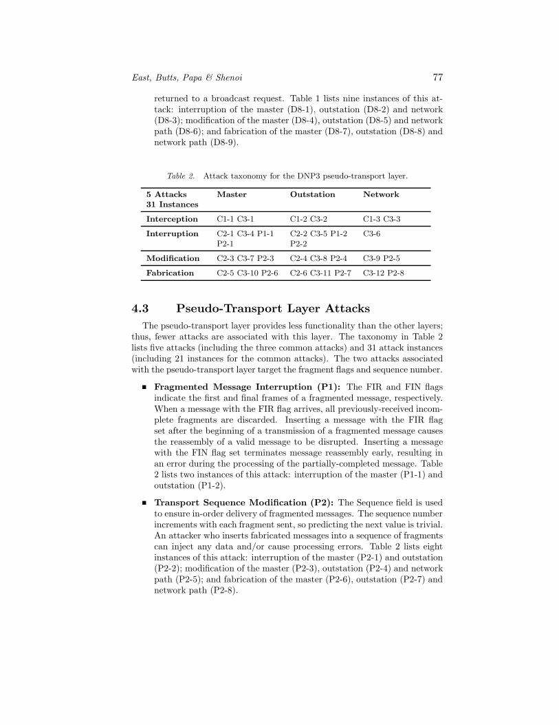
Table 2. Attack taxonomy for the DNP3 pseudo-transport layer.
5 Attacks31 Instances
Master Outstation Network
Interception C1-1 C3-1 C1-2 C3-2 C1-3 C3-3
Interruption C2-1 C3-4 P1-1P2-1
C2-2 C3-5 P1-2P2-2
C3-6
Modification C2-3 C3-7 P2-3 C2-4 C3-8 P2-4 C3-9 P2-5
Fabrication C2-5 C3-10 P2-6 C2-6 C3-11 P2-7 C3-12 P2-8
4.3 Pseudo-Transport Layer Attacks
The pseudo-transport layer provides less functionality than the other layers;thus, fewer attacks are associated with this layer. The taxonomy in Table 2lists five attacks (including the three common attacks) and 31 attack instances(including 21 instances for the common attacks). The two attacks associatedwith the pseudo-transport layer target the fragment flags and sequence number.
Fragmented Message Interruption (P1): The FIR and FIN flagsindicate the first and final frames of a fragmented message, respectively.When a message with the FIR flag arrives, all previously-received incom-plete fragments are discarded. Inserting a message with the FIR flagset after the beginning of a transmission of a fragmented message causesthe reassembly of a valid message to be disrupted. Inserting a messagewith the FIN flag set terminates message reassembly early, resulting inan error during the processing of the partially-completed message. Table2 lists two instances of this attack: interruption of the master (P1-1) andoutstation (P1-2).
Transport Sequence Modification (P2): The Sequence field is usedto ensure in-order delivery of fragmented messages. The sequence numberincrements with each fragment sent, so predicting the next value is trivial.An attacker who inserts fabricated messages into a sequence of fragmentscan inject any data and/or cause processing errors. Table 2 lists eightinstances of this attack: interruption of the master (P2-1) and outstation(P2-2); modification of the master (P2-3), outstation (P2-4) and networkpath (P2-5); and fabrication of the master (P2-6), outstation (P2-7) andnetwork path (P2-8).

78 CRITICAL INFRASTRUCTURE PROTECTION III
Table 3. Attack taxonomy for the DNP3 application layer.
17 Attacks48 Instances
Master Outstation Network
Interception C1-1 C3-1 C1-2 C3-2 A2-1A14-1
C1-3 C3-3
Interruption C2-1 C3-4A10-1 A11-1A12-1 A13-1
C2-2 C3-5 A1-1A2-2 A3-1 A4-1A5-1 A6-1 A7-1A8-1 A9-1
C3-6
Modification C2-3 C3-7A10-2 A11-2A12-2 A13-2
C2-4 C3-8 A1-2A3-2 A4-2 A5-2A6-2 A7-2 A8-2A9-2
C3-9
Fabrication C2-5 C3-10 C2-6 C3-11 C3-12
4.4 Application Layer Attacks
The application layer provides the majority of functionality for DNP3 sys-tems; consequently, the largest number of attacks are associated with this layer.The taxonomy in Table 3 lists seventeen attacks (including the three commonattacks) and 48 attack instances (including 21 instances for the common at-tacks). Attacks on confidentiality obtain information about network topology,system configuration and functionality. Integrity attacks modify communica-tion paths, provide bad data to the master and outstation devices, or recon-figure outstation devices. Availability attacks may cause devices to lose keyfunctionality, reboot or crash. We discuss five attacks in more detail.
Outstation Write Attack (A3): This attack sends a DNP3 messagewith Function Code 2, which writes data objects to an outstation. Theattack can corrupt information stored in the outstation’s memory, causingan error or overflow. Table 3 lists two instances of this attack: interrup-tion (A3-1) and modification (A3-2) of an outstation.
Clear Objects Attack (A4): This attack sends a DNP3 message withFunction Code 9 or 10 to freeze and clear data objects. The attack canclear critical data or cause an outstation device to malfunction or crash.Note that the attack involving Function Code 10 is problematic becausea message with this function code does not require an acknowledgement.Table 3 lists two instances of this attack: interruption (A4-1) and modi-fication (A4-2) of an outstation.
Outstation Data Reset (A6): This attack sends a DNP3 message withFunction Code 15. The attack causes an outstation device to reinitializedata objects to values inconsistent with the state of the system. Table

East, Butts, Papa & Shenoi 79
3 lists two instances of this attack: interruption (A6-1) and modification(A6-2) of an outstation.
Outstation Application Termination (A7): This attack sends aDNP3 message with Function Code 18, which is used to terminate ap-plications running on outstations. A message with this function codecauses a device to become unresponsive to normal requests from the mas-ter. Table 3 lists two instances of this attack: interruption (A7-1) andmodification (A7-2) of an outstation.
Configuration Capture Attack (A14): This attack sends a messagewith the fifth bit in the second byte of the IIN set, which indicates thatthe configuration file of the targeted outstation is corrupted. The attackcauses the master to transmit a new configuration file, which is inter-cepted by the attacker. A separate attack is then executed to modify andupload the file to the targeted outstation. Table 3 lists the one instanceof this attack: interception of outstation data (A14-1).
Table 4. Impact of attacks on target assets.
28 Attacks91 Instances
Master Outstation Network
Interception 2 ObtainMaster Data
4 ObtainOutstation Data
2 ObtainNetwork Data
Interruption 14 DoSMaster
20 DoSOutstation
5 DoSNetwork
Modification 11 Bad Datain Master
15 Bad Data inOutstation
4 ReconfigureNetwork Path
Fabrication 5 ControlProcess
5 FabricateOutstation
4 FabricateNetwork Path
5. Attack Impact
Table 4 summarizes the overall impact of the attacks on control system as-sets. Eight attack instances intercept device configuration data, process dataand network information. Additionally, 39 attack instances result in denial ofservice (DoS); fourteen instances impact the master, twenty impact outstationdevices and five impact network resources. Modification attacks insert erro-neous data in devices, which affects the integrity of the control system. Elevenattack instances insert bad data in the master, fifteen in outstation devices, andfour affect network paths. Fabrication attacks are particularly dangerous. Fiveattack instances enable an attacker to spoof outstation devices and four attackinstances fabricate network paths. Most alarming are the five attack instancesthat spoof the master and seize partial or complete control of the process.

80 CRITICAL INFRASTRUCTURE PROTECTION III
Table 5. Impact of attacks on control objectives.
Data LinkLayer
Pseudo-TransportLayer
ApplicationLayer
Common(All Layers)
Loss ofConfidentiality
0(0) 0(0) 2(2) 6(2)
Loss ofAwareness
33(9) 10(2) 25(13) 15(2)
Loss ofControl
29(9) 7(2) 25(13) 13(2)
Table 5 clarifies the impact of the attacks with respect to the principal in-dustrial control system objectives of process confidentiality, process awarenessand process control. Loss of confidentiality occurs when important informationabout device configuration or network topology is obtained by an attacker.Generally, this is the first step of a more serious attack, where reconnaissanceis conducted to identify weaknesses and entry points. Loss of awareness occurswhen the control center does not have accurate information about system sta-tus. For example, an attacker can trip a circuit breaker and prevent an alarmfrom reaching the operator. Such attacks can lead to serious incidents becausetheir effects may go unnoticed until it is too late. Even more dangerous arethe attacks that result in the loss of control – an attacker who usurps controlof a SCADA master can potentially wreak havoc. Table 5 lists the numbersof attack instances and distinct attacks (in parentheses) that impact the threecontrol system objectives. For example, two application layer attack instances(two attacks) result in a loss of confidentiality, and thirteen common attackinstances (two common attacks) result in loss of control.
6. Conclusions
Our detailed analysis of the DNP3 protocol layers with respect to threatsand targets has identified 28 attacks and 91 attack instances. The effects of theattacks range from obtaining network or device configuration data to corruptingoutstation devices and seizing control of the master unit. It is important tonote that our analysis, while detailed, is by no means comprehensive. In fact,we believe that many more attacks remain to be discovered. Most surprisingis the large proportion of high-impact attacks, especially those involving theinterruption, modification and fabrication of control system assets.
We hope that our work will stimulate efforts focused on analyzing SCADAprotocols and characterizing cyber attacks on the electrical power grid. Theresults will contribute to the security of existing critical infrastructure assets aswell as the design of next generation SCADA systems that are secure, reliableand resilient.

East, Butts, Papa & Shenoi 81
References
[1] G. Clarke and D. Reynolds, Practical Modern SCADA Protocols: DNP3,IEC 60870.5 and Related Systems, Newnes, Oxford, United Kingdom,2004.
[2] K. Curtis, A DNP3 Protocol Primer (Revision A), DNP3 Users Group,Calgary, Canada (www.dnp.org/About/DNP3%20Primer%20Rev%20A.pdf), 2005.
[3] DNP Users Group, Pasadena, California (www.dnp.org), 2008.
[4] Electric Power Research Institute, DNP Security Development, Eval-uation and Testing Project Opportunity, Palo Alto, California (my-docs.epri.com/docs/public/000000000001016988.pdf), 2008.
[5] P. Huber and M. Mills, Brawn and brains, Forbes, September 15, 2003.
[6] P. Huitsing, R. Chandia, M. Papa and S. Shenoi, Attack taxonomies for theModbus protocols, International Journal of Critical Infrastructure Protec-tion, vol. 1, pp. 37–44, 2008.
[7] Institute for Security Technology Studies, Cyber Security of the ElectricPower Industry, Dartmouth College, Hanover, New Hampshire (www.ists.dartmouth.edu/library/218.pdf), 2002.
[8] J. Meserve, Mouse click could plunge city into darkness, expertssay, CNN.com (www.cnn.com/2007/US/09/27/power.at.risk/index.html),September 27, 2007.
[9] C. Pfleeger and S. Lawrence-Pfleeger, Security in Computing, PrenticeHall, Upper Saddle River, New Jersey, 2007.
[10] M. Smith, DNP V3.00 Transport Functions, DNP Users Group, Pasadena,California, 1992.
[11] M. Smith and J. McFadyen, DNP V3.00 Application Layer Protocol De-scription, DNP Users Group, Pasadena, California, 1991.
[12] M. Smith and J. McFadyen, DNP V3.00 Data Link Layer Protocol De-scription, DNP Users Group, Pasadena, California, 2000.
[13] Sun Microsystems, Secure Enterprise Computing with the Solaris 8 Op-erating Environment, Palo Alto, California (www.sun.com/software/whitepapers/wp-s8security/wp-s8security.pdf), 2000.
[14] M. Thesing, DNP3 Specification Volume 7: IP Networking, DNP UsersGroup, Pasadena, California, 1998.
[15] Triangle MicroWorks, DNP3 Overview, Raleigh, North Carolina (www.trianglemicroworks.com /documents/DNP3 Overview.pdf), 2002.