dnp3 communication protocol manual - abb group · communication protocol manual, dnp3 1mrk 511...
TRANSCRIPT

Relion® Protection and Control
650 series ANSIDNP3 Communication Protocol Manual

Document ID: 1MRK 511 257-UUSIssued: June 2012
Revision: AProduct version: 1.2
© Copyright 2012 ABB. All rights reserved
CopyrightThis document and parts thereof must not be reproduced or copied without writtenpermission from ABB, and the contents thereof must not be imparted to a third party,nor used for any unauthorized purpose.
The software and hardware described in this document is furnished under a license andmay be used or disclosed only in accordance with the terms of such license.
TrademarksABB and Relion are registered trademarks of the ABB Group. All other brand orproduct names mentioned in this document may be trademarks or registeredtrademarks of their respective holders.
WarrantyPlease inquire about the terms of warranty from your nearest ABB representative.
ABB Inc.
1021 Main Campus Drive
Raleigh, NC 27606, USA
Toll Free: 1-800-HELP-365, menu option #8
ABB Inc.
3450 Harvester Road
Burlington, ON L7N 3W5, Canada
Toll Free: 1-800-HELP-365, menu option #8
ABB Mexico S.A. de C.V.
Paseo de las Americas No. 31 Lomas Verdes 3a secc.
53125, Naucalpan, Estado De Mexico, MEXICO
Phone: (+1) 440-585-7804, menu option #8
DisclaimerThe data, examples and diagrams in this manual are included solely for the concept orproduct description and are not to be deemed as a statement of guaranteed properties.All persons responsible for applying the equipment addressed in this manual mustsatisfy themselves that each intended application is suitable and acceptable, includingthat any applicable safety or other operational requirements are complied with. Inparticular, any risks in applications where a system failure and/or product failure wouldcreate a risk for harm to property or persons (including but not limited to personalinjuries or death) shall be the sole responsibility of the person or entity applying theequipment, and those so responsible are hereby requested to ensure that all measuresare taken to exclude or mitigate such risks.
This document has been carefully checked by ABB but deviations cannot becompletely ruled out. In case any errors are detected, the reader is kindly requested tonotify the manufacturer. Other than under explicit contractual commitments, in noevent shall ABB be responsible or liable for any loss or damage resulting from the useof this manual or the application of the equipment.

ConformityThis product complies with the directive of the Council of the European Communitieson the approximation of the laws of the Member States relating to electromagneticcompatibility (EMC Directive 2004/108/EC) and concerning electrical equipment foruse within specified voltage limits (Low-voltage directive 2006/95/EC). Thisconformity is the result of tests conducted by ABB in accordance with the productstandards EN 50263 and EN 60255-26 for the EMC directive, and with the productstandards EN 60255-1 and EN 60255-27 for the low voltage directive. The product isdesigned in accordance with the international standards of the IEC 60255 series andANSI C37.90. The DNP protocol implementation in the IED conforms to "DNP3Intelligent Electronic Device (IED) Certification Procedure Subset Level 2", availableat www.dnp.org .
Table of contents
Section 1 Introduction............................................................................3This manual..............................................................................................3Intended audience....................................................................................3Product documentation.............................................................................4
Product documentation set..................................................................4Document revision history...................................................................5Related documents..............................................................................6
Symbols and conventions.........................................................................7Symbols...............................................................................................7Document conventions........................................................................8Functions included in 650 series IEDs................................................8
Section 2 DNP3 overview....................................................................17DNP3 standard.......................................................................................17Documentation........................................................................................20
Section 3 Vendor-specific implementation..........................................21DNP3 link modes....................................................................................21
DNP3 TCP/IP mode...........................................................................21Internal indications..................................................................................22Event reporting.......................................................................................23
Event buffers.....................................................................................23Command handling.................................................................................24
Automation bits..................................................................................24Apparatus control..............................................................................24Binary output status points and control relay output blocks..............24
Time synchronization..............................................................................25Analog inputs..........................................................................................25
Analog data scaling...........................................................................26Analog input signal scaling for DNP3 master presentation...............26
DNP3 points............................................................................................29Point configuration.............................................................................29Class assignment..............................................................................29
Fault record.............................................................................................29
Section 4 DNP3 parameters................................................................31Parameter descriptions...........................................................................31
Table of contents
650 series ANSI 1Communication Protocol Manual

Serial optical and RS485 communication channel settings...............35Parameter list..........................................................................................37
Parameter list for optical and RS485 communication channel..........37Parameter list for TCP/IP...................................................................42
Section 5 Glossary..............................................................................55
Table of contents
2 650 series ANSICommunication Protocol Manual
Section 1 Introduction
1.1 This manual
The communication protocol manual describes a communication protocol supported bythe IED. The manual concentrates on vendor-specific implementations.
1.2 Intended audience
This manual addresses the communication system engineer or system integratorresponsible for pre-engineering and engineering for communication setup in asubstation from an IED perspective.
The system engineer or system integrator must have a basic knowledge ofcommunication in protection and control systems and thorough knowledge of thespecific communication protocol.
1MRK 511 257-UUS A Section 1Introduction
650 series ANSI 3Communication Protocol Manual
1.3 Product documentation
1.3.1 Product documentation set
Pla
nnin
g &
pur
chas
e
Eng
inee
ring
Inst
allin
g
Com
mis
sion
ing
Ope
ratio
n
Mai
nten
ance
Dec
omm
issi
onin
gde
inst
allin
g&
dis
posa
l
Application manual
Operation manual
Installation manual
Service manual
Engineering manual
Commissioning manual
Communication protocolmanual
Technical manual
Pla
nnin
g &
pur
chas
e
Eng
inee
ring
Inst
allin
g
Com
mis
sion
ing
Ope
ratio
n
Mai
nten
ance
Dec
omm
issi
onin
gde
inst
allin
g&
dis
posa
l
Pla
nnin
g &
pur
chas
e
Eng
inee
ring
Inst
allin
g
Com
mis
sion
ing
Ope
ratio
n
Mai
nten
ance
Dec
omm
issi
onin
gde
inst
allin
g&
dis
posa
l
Application manualApplication manual
Operation manualOperation manual
Installation manualInstallation manual
Service manualService manual
Engineering manualEngineering manual
Commissioning manualCommissioning manual
Communication protocolmanualCommunication protocolmanual
Technical manualTechnical manual
en07000220.vsd
IEC07000220 V1 EN
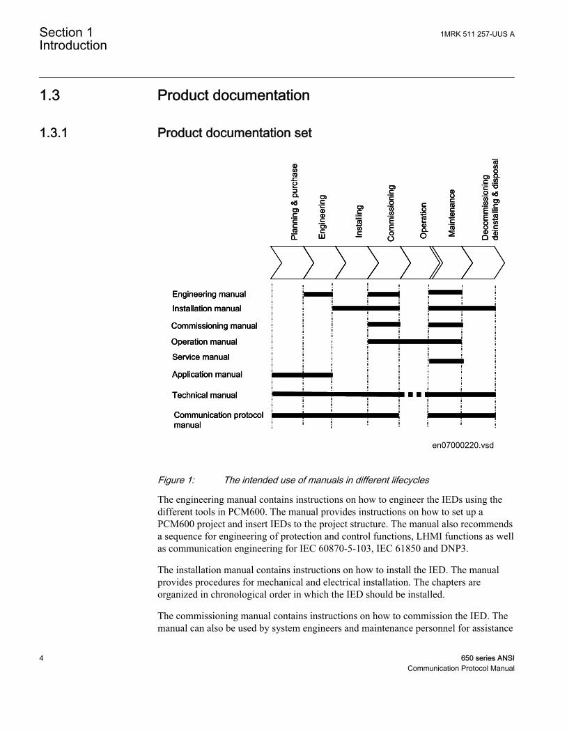
Figure 1: The intended use of manuals in different lifecycles
The engineering manual contains instructions on how to engineer the IEDs using thedifferent tools in PCM600. The manual provides instructions on how to set up aPCM600 project and insert IEDs to the project structure. The manual also recommendsa sequence for engineering of protection and control functions, LHMI functions as wellas communication engineering for IEC 60870-5-103, IEC 61850 and DNP3.
The installation manual contains instructions on how to install the IED. The manualprovides procedures for mechanical and electrical installation. The chapters areorganized in chronological order in which the IED should be installed.
The commissioning manual contains instructions on how to commission the IED. Themanual can also be used by system engineers and maintenance personnel for assistance
Section 1 1MRK 511 257-UUS AIntroduction
4 650 series ANSICommunication Protocol Manual
during the testing phase. The manual provides procedures for checking of externalcircuitry and energizing the IED, parameter setting and configuration as well asverifying settings by secondary injection. The manual describes the process of testingan IED in a substation which is not in service. The chapters are organized inchronological order in which the IED should be commissioned.
The operation manual contains instructions on how to operate the IED once it has beencommissioned. The manual provides instructions for monitoring, controlling andsetting the IED. The manual also describes how to identify disturbances and how toview calculated and measured power grid data to determine the cause of a fault.
The service manual contains instructions on how to service and maintain the IED. Themanual also provides procedures for de-energizing, de-commissioning and disposal ofthe IED.
The application manual contains application descriptions and setting guidelines sortedper function. The manual can be used to find out when and for what purpose a typicalprotection function can be used. The manual can also be used when calculating settings.
The technical manual contains application and functionality descriptions and listsfunction blocks, logic diagrams, input and output signals, setting parameters andtechnical data sorted per function. The manual can be used as a technical referenceduring the engineering phase, installation and commissioning phase, and during normalservice.
The communication protocol manual describes a communication protocol supported bythe IED. The manual concentrates on vendor-specific implementations.
The point list manual describes the outlook and properties of the data points specific tothe IED. The manual should be used in conjunction with the correspondingcommunication protocol manual.
1.3.2 Document revision historyDocument revision/date History-/March 2012 First release
A/June 2012 Minor corrections made
1MRK 511 257-UUS A Section 1Introduction
650 series ANSI 5Communication Protocol Manual
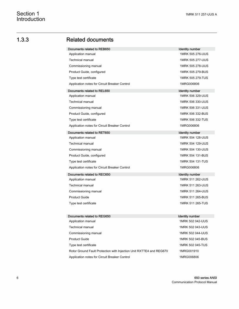
1.3.3 Related documentsDocuments related to REB650 Identity numberApplication manual 1MRK 505 276-UUS
Technical manual 1MRK 505 277-UUS
Commissioning manual 1MRK 505 278-UUS
Product Guide, configured 1MRK 505 279-BUS
Type test certificate 1MRK 505 279-TUS
Application notes for Circuit Breaker Control 1MRG006806
Documents related to REL650 Identity numberApplication manual 1MRK 506 329-UUS
Technical manual 1MRK 506 330-UUS
Commissioning manual 1MRK 506 331-UUS
Product Guide, configured 1MRK 506 332-BUS
Type test certificate 1MRK 506 332-TUS
Application notes for Circuit Breaker Control 1MRG006806
Documents related to RET650 Identity numberApplication manual 1MRK 504 128-UUS
Technical manual 1MRK 504 129-UUS
Commissioning manual 1MRK 504 130-UUS
Product Guide, configured 1MRK 504 131-BUS
Type test certificate 1MRK 504 131-TUS
Application notes for Circuit Breaker Control 1MRG006806
Documents related to REC650 Identity numberApplication manual 1MRK 511 262-UUS
Technical manual 1MRK 511 263-UUS
Commissioning manual 1MRK 511 264-UUS
Product Guide 1MRK 511 265-BUS
Type test certificate 1MRK 511 265-TUS
Documents related to REG650 Identity numberApplication manual 1MRK 502 042-UUS
Technical manual 1MRK 502 043-UUS
Commissioning manual 1MRK 502 044-UUS
Product Guide 1MRK 502 045-BUS
Type test certificate 1MRK 502 045-TUS
Rotor Ground Fault Protection with Injection Unit RXTTE4 and REG670 1MRG001910
Application notes for Circuit Breaker Control 1MRG006806
Section 1 1MRK 511 257-UUS AIntroduction
6 650 series ANSICommunication Protocol Manual
Documents related to REQ650 Identity numberApplication manual 1MRK 505 280-UUS
Technical manual 1MRK 505 281-UUS
Commissioning manual 1MRK 505 282-UUS
Product Guide 1MRK 505 283-BUS
Type test certificate 1MRK 505 283-TUS
Application notes for Circuit Breaker Control 1MRG006806
650 series manuals Identity numberCommunication protocol manual, DNP3 1MRK 511 257-UUS
Communication protocol manual, IEC 61850–8–1 1MRK 511 258-UUS
Communication protocol manual, IEC 60870-5-103 1MRK 511 259-UUS
Cyber Security deployment guidelines 1MRK 511 268-UUS
Point list manual, DNP3 1MRK 511 260-UUS
Engineering manual 1MRK 511 261-UUS
Operation manual 1MRK 500 095-UUS
Installation manual 1MRK 514 015-UUS
1.4 Symbols and conventions
1.4.1 Symbols
The caution icon indicates important information or warning related tothe concept discussed in the text. It might indicate the presence of ahazard which could result in corruption of software or damage toequipment or property.
The information icon alerts the reader of important facts and conditions.
The tip icon indicates advice on, for example, how to design yourproject or how to use a certain function.
Although warning hazards are related to personal injury, it is necessary to understandthat under certain operational conditions, operation of damaged equipment may result
1MRK 511 257-UUS A Section 1Introduction
650 series ANSI 7Communication Protocol Manual
in degraded process performance leading to personal injury or death. Therefore,comply fully with all warning and caution notices.
1.4.2 Document conventionsA particular convention may not be used in this manual.
• Abbreviations and acronyms in this manual are spelled out in the glossary. Theglossary also contains definitions of important terms.
• Push button navigation in the LHMI menu structure is presented by using the pushbutton icons.To navigate between the options, use and .
• HMI menu paths are presented in bold.Select Main menu/Settings.
• LHMI messages are shown in Courier font.To save the changes in non-volatile memory, select Yes and press .
• Parameter names are shown in italics.The function can be enabled and disabled with the Operation setting.
• The ^ character in front of an input or output signal name in the function blocksymbol given for a function, indicates that the user can set an own signal name inPCM600.
• The * character after an input or output signal name in the function block symbolgiven for a function, indicates that the signal must be connected to anotherfunction block in the application configuration to achieve a valid applicationconfiguration.
• Dimensions are provided both in inches and mm. If it is not specifically mentionedthen the dimension is in mm.
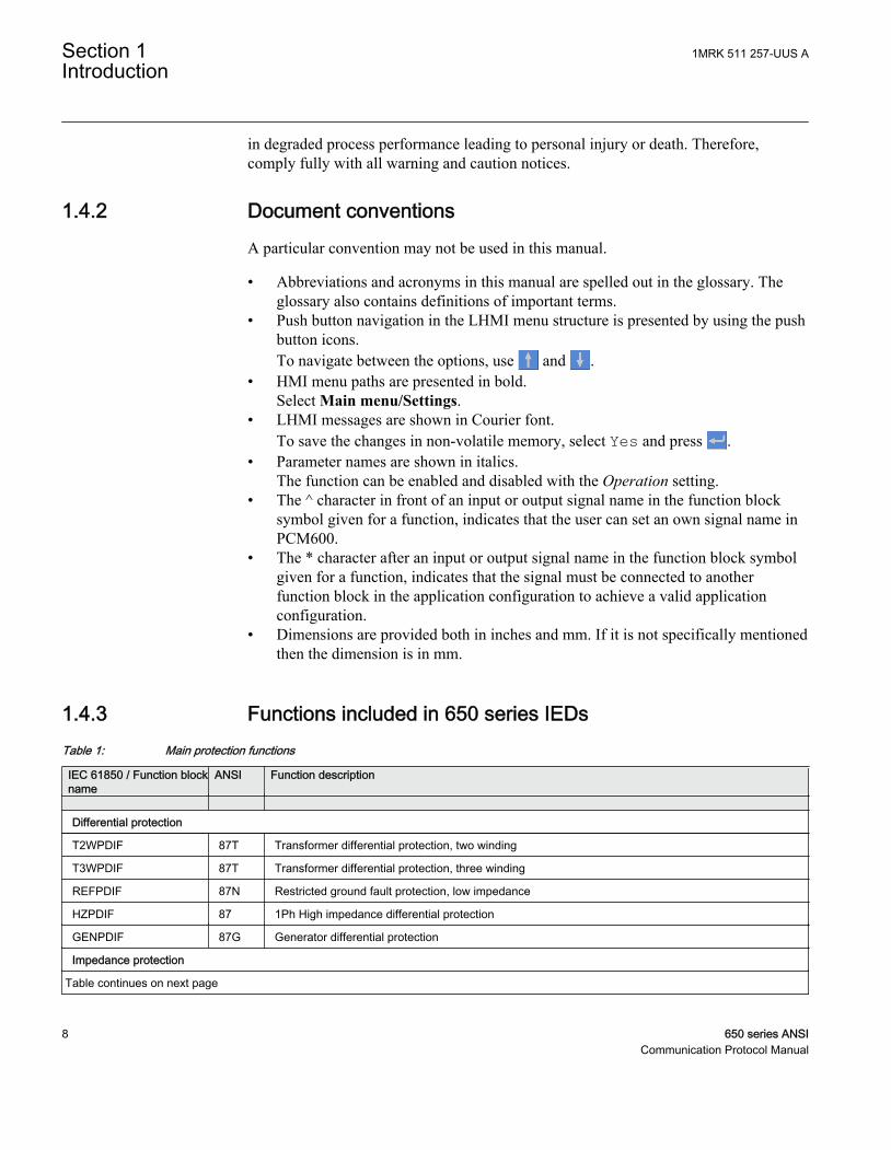
1.4.3 Functions included in 650 series IEDsTable 1: Main protection functions
IEC 61850 / Function blockname
ANSI Function description
Differential protection
T2WPDIF 87T Transformer differential protection, two winding
T3WPDIF 87T Transformer differential protection, three winding
REFPDIF 87N Restricted ground fault protection, low impedance
HZPDIF 87 1Ph High impedance differential protection
GENPDIF 87G Generator differential protection
Impedance protection
Table continues on next page
Section 1 1MRK 511 257-UUS AIntroduction
8 650 series ANSICommunication Protocol Manual

IEC 61850 / Function blockname
ANSI Function description
ZQMPDIS 21 Five-zone distance protection, Quadrilateral and Mho characteristic
FDPSPDIS 21 Phase selection with load enchroachment, quadrilateral characteristic
FMPSPDIS 21 Faulty phase identification with load enchroachment for mho
ZDARDIR 21 Additional distance protection directional function for ground faults
ZDNRDIR 21 Directional impedance quadrilateral and mho
PPLPHIZ Phase preference logic
ZMRPSB 68 Power swing detection
ZCVPSOF Automatic switch onto fault logic, voltage-and current-based
ZGCPDIS 21G Underimpedance protection for generators and transformers
LEXPDIS 40 Loss of excitation
OOSPPAM 78 Out-of-step protection
LEPDIS Load enchroachment
Table 2: Backup protection functions
IEC 61850 / Functionblock name
ANSI Function description
Current protection
PHPIOC 50 Instantaneous phase overcurrent protection
SPTPIOC 50 Instantaneous phase overcurrent protection
OC4PTOC 51/67 Four-step phase overcurrent protection
OC4SPTOC 51/67 Four-step phase overcurrent protection
EFPIOC 50N Instantaneous residual overcurrent protection
EF4PTOC 51N/67N Four-step directional residual overcurrent protection
SDEPSDE 67N Sensitive directional residual overcurrent and power protection
UC2PTUC 37 Time-delayed two-step undercurrent protection
LCPTTR 26 Thermal overload protection, one time constant, Celsius
LFPTTR 26 Thermal overload protection, one time constant, Fahrenheit
TRPTTR 49 Thermal overload protection, two time constants
CCRBRF 50BF Breaker failure protection
CSPRBRF 50BF Breaker failure protection
STBPTOC 50STB Stub protection
CCRPLD 52PD Pole discordance protection
BRCPTOC 46 Broken conductor check
GUPPDUP 37 Directional underpower protection
Table continues on next page
1MRK 511 257-UUS A Section 1Introduction
650 series ANSI 9Communication Protocol Manual

IEC 61850 / Functionblock name
ANSI Function description
GOPPDOP 32 Directional overpower protection
DNSPTOC 46 Negative sequence-based overcurrent function
AEGGAPC 50AE Accidental energizing protection for synchronous generator
NS2PTOC 46I2 Negative-sequence time overcurrent protection for machines
VR2PVOC 51V Voltage-restrained time overcurrent protection
Voltage protection
UV2PTUV 27 Two-step undervoltage protection
OV2PTOV 59 Two-step overvoltage protection
ROV2PTOV 59N Two-step residual overvoltage protection
OEXPVPH 24 Overexcitation protection
LOVPTUV 27 Loss-of-voltage check
STEFPHIZ 59THD 100% Stator ground fault protection, 3rd harmonic based
Frequency protection
SAPTUF 81 Underfrequency function
SAPTOF 81 Overfrequency function
SAPFRC 81 Rate-of-change frequency protection
Table 3: Control and monitoring functions
IEC 61850 / Functionblock name
ANSI Function description
Control
SESRSYN 25 Synchrocheck, energizing check and synchronizing
SMBRREC 79 Autorecloser
STBRREC 79 Autorecloser
SCILO 3 Logical node for interlocking
BB_ES 3 Interlocking for busbar grounding switch
A1A2_BS 3 Interlocking for bus-section breaker
A1A2_DC 3 Interlocking for bus-section disconnector
ABC_BC 3 Interlocking for bus-coupler bay
BH_CONN 3 Interlocking for 1 1/2 breaker diameter
BH_LINE_A 3 Interlocking for 1 1/2 breaker diameter
BH_LINE_B 3 Interlocking for 1 1/2 breaker diameter
DB_BUS_A 3 Interlocking for double CB bay
DB_BUS_B 3 Interlocking for double CB bay
Table continues on next page
Section 1 1MRK 511 257-UUS AIntroduction
10 650 series ANSICommunication Protocol Manual
IEC 61850 / Functionblock name
ANSI Function description
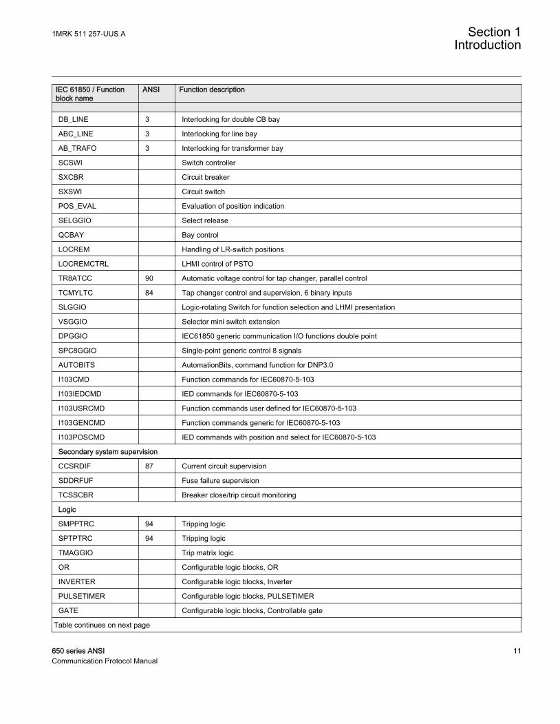
DB_LINE 3 Interlocking for double CB bay
ABC_LINE 3 Interlocking for line bay
AB_TRAFO 3 Interlocking for transformer bay
SCSWI Switch controller
SXCBR Circuit breaker
SXSWI Circuit switch
POS_EVAL Evaluation of position indication
SELGGIO Select release
QCBAY Bay control
LOCREM Handling of LR-switch positions
LOCREMCTRL LHMI control of PSTO
TR8ATCC 90 Automatic voltage control for tap changer, parallel control
TCMYLTC 84 Tap changer control and supervision, 6 binary inputs
SLGGIO Logic-rotating Switch for function selection and LHMI presentation
VSGGIO Selector mini switch extension
DPGGIO IEC61850 generic communication I/O functions double point
SPC8GGIO Single-point generic control 8 signals
AUTOBITS AutomationBits, command function for DNP3.0
I103CMD Function commands for IEC60870-5-103
I103IEDCMD IED commands for IEC60870-5-103
I103USRCMD Function commands user defined for IEC60870-5-103
I103GENCMD Function commands generic for IEC60870-5-103
I103POSCMD IED commands with position and select for IEC60870-5-103
Secondary system supervision
CCSRDIF 87 Current circuit supervision
SDDRFUF Fuse failure supervision
TCSSCBR Breaker close/trip circuit monitoring
Logic
SMPPTRC 94 Tripping logic
SPTPTRC 94 Tripping logic
TMAGGIO Trip matrix logic
OR Configurable logic blocks, OR
INVERTER Configurable logic blocks, Inverter
PULSETIMER Configurable logic blocks, PULSETIMER
GATE Configurable logic blocks, Controllable gate
Table continues on next page
1MRK 511 257-UUS A Section 1Introduction
650 series ANSI 11Communication Protocol Manual
IEC 61850 / Functionblock name
ANSI Function description
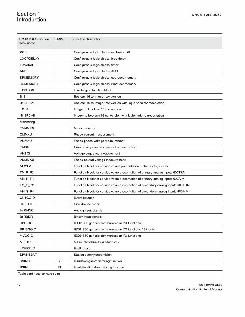
XOR Configurable logic blocks, exclusive OR
LOOPDELAY Configurable logic blocks, loop delay
TimerSet Configurable logic blocks, timer
AND Configurable logic blocks, AND
SRMEMORY Configurable logic blocks, set-reset memory
RSMEMORY Configurable logic blocks, reset-set memory
FXDSIGN Fixed-signal function block
B16I Boolean 16 to Integer conversion
B16IFCVI Boolean 16 to Integer conversion with logic node representation
IB16A Integer to Boolean 16 conversion
IB16FCVB Integer to boolean 16 conversion with logic node representation
Monitoring
CVMMXN Measurements
CMMXU Phase current measurement
VMMXU Phase-phase voltage measurement
CMSQI Current sequence component measurement
VMSQI Voltage sequence measurement
VNMMXU Phase-neutral voltage measurement
AISVBAS Function block for service values presentation of the analog inputs
TM_P_P2 Function block for service value presentation of primary analog inputs 600TRM
AM_P_P4 Function block for service value presentation of primary analog inputs 600AIM
TM_S_P2 Function block for service value presentation of secondary analog inputs 600TRM
AM_S_P4 Function block for service value presentation of secondary analog inputs 600AIM
CNTGGIO Event counter
DRPRDRE Disturbance report
AxRADR Analog input signals
BxRBDR Binary input signals
SPGGIO IEC61850 generic communication I/O functions
SP16GGIO IEC61850 generic communication I/O functions 16 inputs
MVGGIO IEC61850 generic communication I/O functions
MVEXP Measured value expander block
LMBRFLO Fault locator
SPVNZBAT Station battery supervision
SSIMG 63 Insulation gas-monitoring function
SSIML 71 Insulation liquid-monitoring function
Table continues on next page
Section 1 1MRK 511 257-UUS AIntroduction
12 650 series ANSICommunication Protocol Manual
IEC 61850 / Functionblock name
ANSI Function description
SSCBR Circuit breaker condition monitoring
I103MEAS Measurands for IEC60870-5-103
I103MEASUSR Measurands user defined signals for IEC60870-5-103
I103AR Function status auto-recloser for IEC60870-5-103
I103EF Function status ground-fault for IEC60870-5-103
I103FLTPROT Function status fault protection for IEC60870-5-103
I103IED IED status for IEC60870-5-103
I103SUPERV Supervision status for IEC60870-5-103
I103USRDEF Status for user defiend signals for IEC60870-5-103
Metering
PCGGIO Pulse counter logic
ETPMMTR Function for energy calculation and demand handling
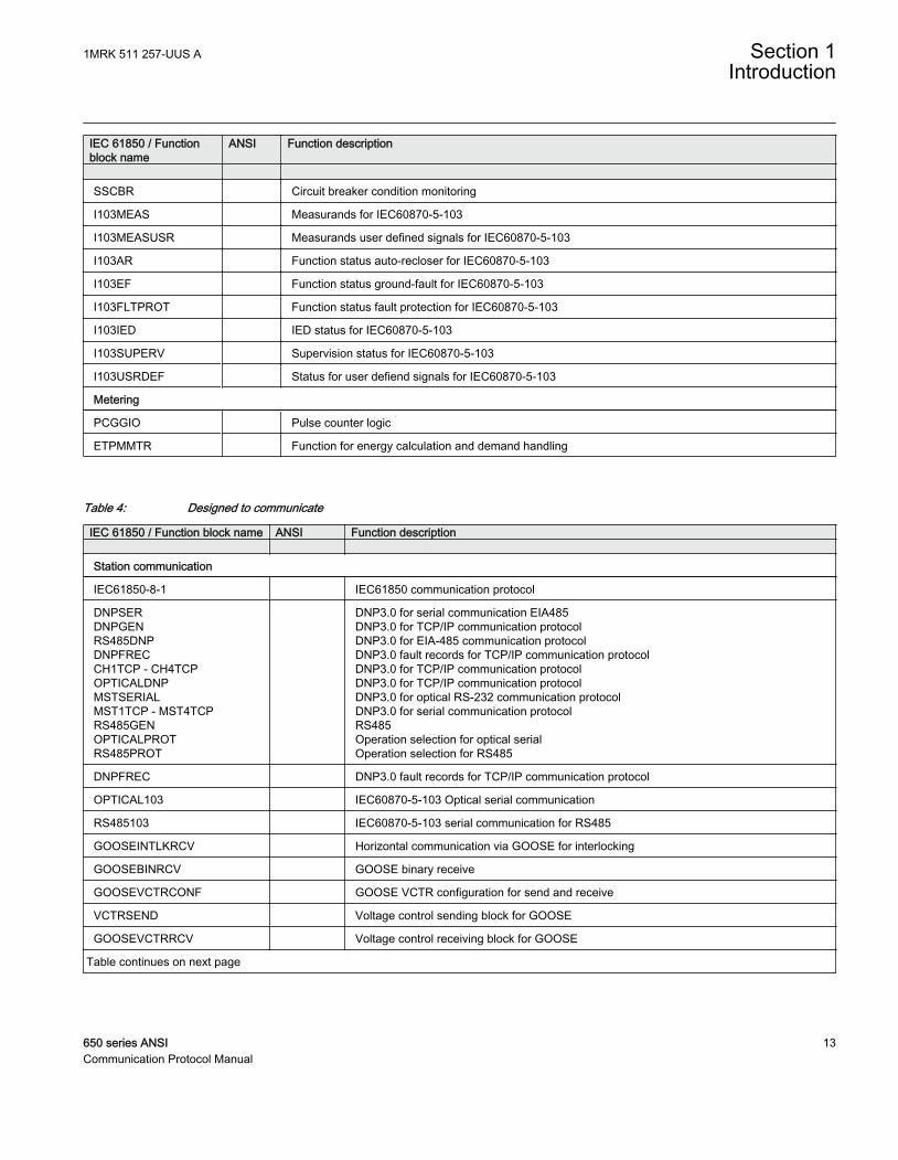
Table 4: Designed to communicate
IEC 61850 / Function block name ANSI Function description Station communication
IEC61850-8-1 IEC61850 communication protocol
DNPSERDNPGENRS485DNPDNPFRECCH1TCP - CH4TCPOPTICALDNPMSTSERIALMST1TCP - MST4TCPRS485GENOPTICALPROTRS485PROT
DNP3.0 for serial communication EIA485DNP3.0 for TCP/IP communication protocolDNP3.0 for EIA-485 communication protocolDNP3.0 fault records for TCP/IP communication protocolDNP3.0 for TCP/IP communication protocolDNP3.0 for TCP/IP communication protocolDNP3.0 for optical RS-232 communication protocolDNP3.0 for serial communication protocolRS485Operation selection for optical serialOperation selection for RS485
DNPFREC DNP3.0 fault records for TCP/IP communication protocol
OPTICAL103 IEC60870-5-103 Optical serial communication
RS485103 IEC60870-5-103 serial communication for RS485
GOOSEINTLKRCV Horizontal communication via GOOSE for interlocking
GOOSEBINRCV GOOSE binary receive
GOOSEVCTRCONF GOOSE VCTR configuration for send and receive
VCTRSEND Voltage control sending block for GOOSE
GOOSEVCTRRCV Voltage control receiving block for GOOSE
Table continues on next page
1MRK 511 257-UUS A Section 1Introduction
650 series ANSI 13Communication Protocol Manual
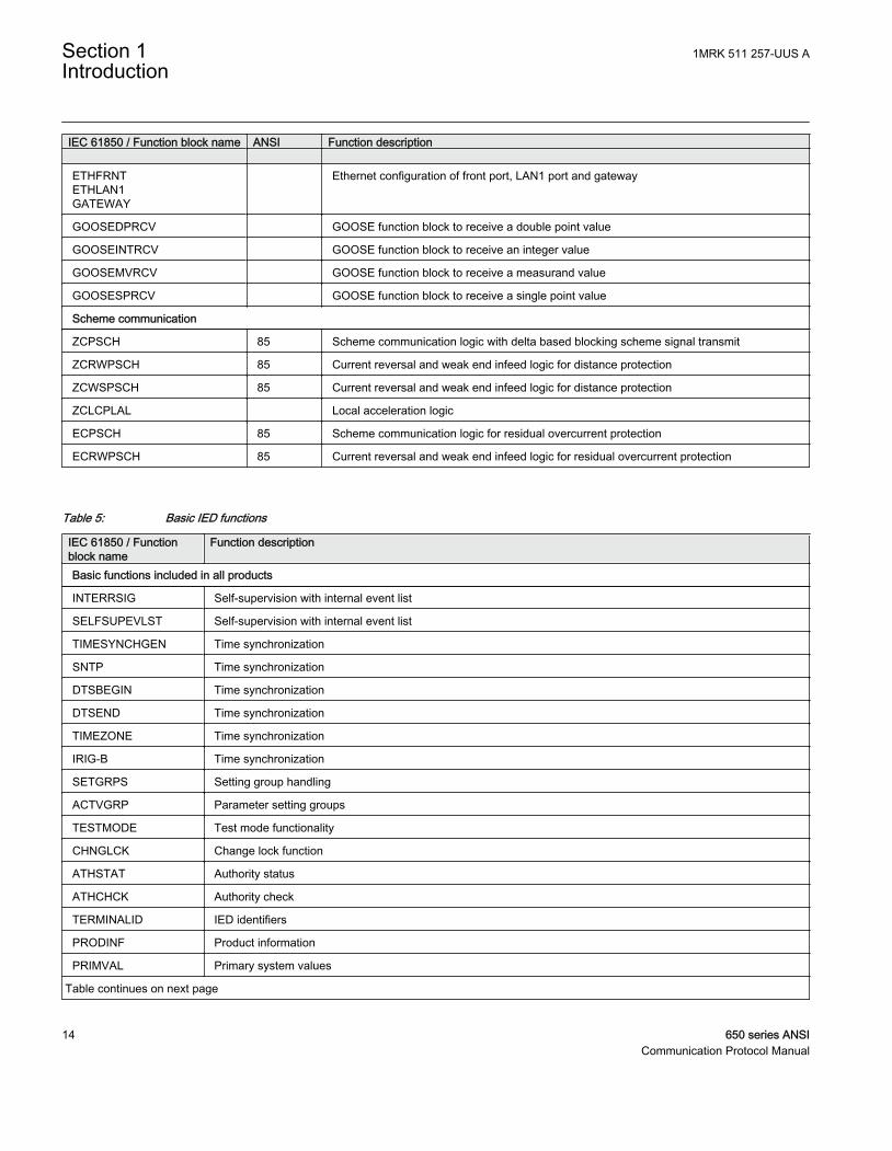
IEC 61850 / Function block name ANSI Function description ETHFRNTETHLAN1GATEWAY
Ethernet configuration of front port, LAN1 port and gateway
GOOSEDPRCV GOOSE function block to receive a double point value
GOOSEINTRCV GOOSE function block to receive an integer value
GOOSEMVRCV GOOSE function block to receive a measurand value
GOOSESPRCV GOOSE function block to receive a single point value
Scheme communication
ZCPSCH 85 Scheme communication logic with delta based blocking scheme signal transmit
ZCRWPSCH 85 Current reversal and weak end infeed logic for distance protection
ZCWSPSCH 85 Current reversal and weak end infeed logic for distance protection
ZCLCPLAL Local acceleration logic
ECPSCH 85 Scheme communication logic for residual overcurrent protection
ECRWPSCH 85 Current reversal and weak end infeed logic for residual overcurrent protection
Table 5: Basic IED functions
IEC 61850 / Functionblock name
Function description
Basic functions included in all products
INTERRSIG Self-supervision with internal event list
SELFSUPEVLST Self-supervision with internal event list
TIMESYNCHGEN Time synchronization
SNTP Time synchronization
DTSBEGIN Time synchronization
DTSEND Time synchronization
TIMEZONE Time synchronization
IRIG-B Time synchronization
SETGRPS Setting group handling
ACTVGRP Parameter setting groups
TESTMODE Test mode functionality
CHNGLCK Change lock function
ATHSTAT Authority status
ATHCHCK Authority check
TERMINALID IED identifiers
PRODINF Product information
PRIMVAL Primary system values
Table continues on next page
Section 1 1MRK 511 257-UUS AIntroduction
14 650 series ANSICommunication Protocol Manual
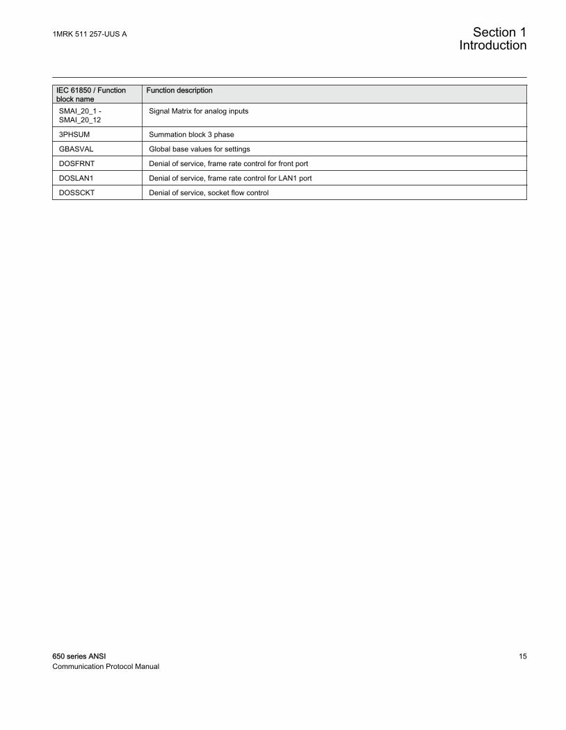
IEC 61850 / Functionblock name
Function description
SMAI_20_1 -SMAI_20_12
Signal Matrix for analog inputs
3PHSUM Summation block 3 phase
GBASVAL Global base values for settings
DOSFRNT Denial of service, frame rate control for front port
DOSLAN1 Denial of service, frame rate control for LAN1 port
DOSSCKT Denial of service, socket flow control
1MRK 511 257-UUS A Section 1Introduction
650 series ANSI 15Communication Protocol Manual

16
Section 2 DNP3 overview
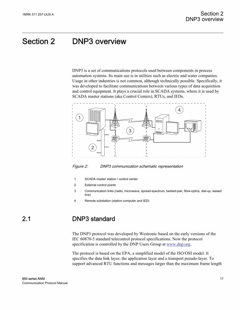
DNP3 is a set of communications protocols used between components in processautomation systems. Its main use is in utilities such as electric and water companies.Usage in other industries is not common, although technically possible. Specifically, itwas developed to facilitate communications between various types of data acquisitionand control equipment. It plays a crucial role in SCADA systems, where it is used bySCADA master stations (aka Control Centers), RTUs, and IEDs.
GUID-F3F7289C-3344-492F-8779-D63CBF6B469A V1 EN
Figure 2: DNP3 communication schematic representation
1 SCADA master station / control center
2 External control points
3 Communication links (radio, microwave, spread-spectrum, twisted-pair, fibre-optics, dial-up, leasedline)
4 Remote substation (station computer and IED)
2.1 DNP3 standard
The DNP3 protocol was developed by Westronic based on the early versions of theIEC 60870-5 standard telecontrol protocol specifications. Now the protocolspecification is controlled by the DNP Users Group at www.dnp.org.
The protocol is based on the EPA, a simplified model of the ISO/OSI model. Itspecifies the data link layer, the application layer and a transport pseudo-layer. Tosupport advanced RTU functions and messages larger than the maximum frame length
1MRK 511 257-UUS A Section 2DNP3 overview
650 series ANSI 17Communication Protocol Manual
as defined by the IEC document 60870-5-1, the DNP3 data link is intended to be usedwith the mentioned transport pseudo-layer. As a minimum, this transport layerimplements message assembly and disassembly services.
Physical layerEven though the standard does not specify the physical layer, it does however specifyhow to operate in a networked environment and also suggests how to avoid collisionsbetween simultaneously sending devices.
Many implementations use serial communication based on RS-232, RS-485 or evenfibre optics.
DNP3 can also be used over packet-oriented networks such as TCP/IP and UDP inwhich, for example, Ethernet may be used. In this case DNP3 can be said to betunneled over TCP/IP or UDP.
Additional information on the DNP3 physical layer is available at theDNP Users Group at www.dnp.org.
Data link layerThe DNP3 data link layer is designed to operate with asynchronous or synchronous bitserial physical layers. Fully balanced transmission procedures were adopted to supportspontaneous transmissions from outstations.
Data link functions include:
• Performing message data link retransmissions.• Synchronizing and handling the FCB in the control octet.• Setting and clearing the DFC bit based on buffer availability.• Packing user data into the defined frame format includes CRC and transmitting the
data to the physical layer.• Unpacking the data link frame received from the physical layer into user data,
checking and removing CRC.• Controlling the physical layer.• In unsolicited reporting mode, performing collision avoidance/detection
procedures to ensure reliable transfer of data across the physical link.• Responding to all valid frames received from the physical layer.
Data link responsibilities:
Section 2 1MRK 511 257-UUS ADNP3 overview
18 650 series ANSICommunication Protocol Manual

• Exchange of SDUs between peer DNP3 data links• Error notification to data link user• Sequencing of SDUs• SDU delivery quality.
Link-layer confirm usage is not recommended and the implementation is optional. TheIED does not request data-link layer confirmations for TCP/IP communication.
See the DNP technical bulletin TB1998-0402, section 3 for details atwww.dnp.org.
Transport pseudo-layerTo support advanced RTU functions and messages exceeding the maximum data linkframe length, a transport pseudo-layer which implements message assembly anddisassembly services was adopted.
Transport functions:
• Fragmenting user data into one or more data link frames and transmitting the datato the data link layer
• Assembling the data link frames received from the data link layer into user data• Controlling all aspects of the data link excluding data link configuration
Transport responsibilities:
• Exchange of SDUs between peer DNP3 transport pseudo layers• Error notification to transport users• Sequencing of SDUs
Application layerThe application layer is responsible for performing operations on data objects definedby the device or on the device itself. These operations include returning actual values(read function), assigning new values (write function) if the object represents controlpoints, arming and energizing the output point (select, operate or direct operatefunctions) and if counters are used, reading actual values and clearing the counters.DNP3 uses the term point do identify an entity, and these entities can be categorizedinto point-types, such as analogs or binaries. Points are addressed by giving them anindex number and an object is a formatted representation of data from a point. Theseobjects can be assigned to classes in order to organize events and current values intocategories. The DNP3 protocol defines four classes; 0 for static data (current value)and 1, 2 and 3 for event data.
1MRK 511 257-UUS A Section 2DNP3 overview
650 series ANSI 19Communication Protocol Manual
Communication modesThe IED supports four DNP3 communication modes.
• Quiescent operation• Unsolicited report-by-exception operation• Polled report-by-exception operation• Polled static operation
2.2 Documentation
This implementation of DNP3 is fully compliant with DNP3 Subset Definition Level 2,and contains significant functionality beyond Subset Level 2. See the device profile forfurther information.
Section 2 1MRK 511 257-UUS ADNP3 overview
20 650 series ANSICommunication Protocol Manual
Section 3 Vendor-specific implementation
3.1 DNP3 link modes
3.1.1 DNP3 TCP/IP modeDNP3 TCP/IP link mode is supported by the IED. This implementation supports up tofour different masters communicating simultaneously with the IED. The IED is alistening endpoint implementation and listens for connections from DNP3 masters on aconfigurable port, TCPIPLisPort. The IED does not connect to masters, meaning that itis not a dual-endpoint implementation.
It is possible to use both the connection establishment method based on the master IPaddress, and the connection establishment method based on the port number. Theidentification and association of the master is based both on the IP address of themaster and the port number it connects to. It is essential to make sure that theparameters TCPIPLisPort, MasterIP-Addr, MasterIPNetMask, SlaveAddress andMasterAddress uniquely identifies one master from the other masters.
The above is an important concept to grasp during commissioning so that no conflictsoccur. Therefore, it is strongly recommended not to change the MasterIPNetMaskparameter to anything else than its default 255.255.255.255 unless necessary. Theparameter should not be mixed up with the subnet mask of the IP configuration. TheMasterIPNetMask can be used to allow to accept connections from masters that dohave dynamic IP addresses within a known range.
For example, if a master changes its IP address dynamically in the range of 10.10.10.1and 10.10.10.254, the MasterIPNetMask could be set to 255.255.255.0 to allow forconnections from this range. If two masters share this dynamic range or share the sameIP address, it is necessary to separate them by having them connect to separate ports,for example, 20000 and 20001 respectively.
Also, SlaveAddress and MasterAddress must be correctly configured for each master.Otherwise, the previously accepted connection is closed upon the reception of the firstDNP3 message.
The IED supports the requirements of the standard to receive UDP broadcast messageson the ports configured by UDPPortAccData. When operating in UDP-only mode,UDPPortInitNULL and UDPPortCliMast need to be configured as well.
1MRK 511 257-UUS A Section 3Vendor-specific implementation
650 series ANSI 21Communication Protocol Manual
As a default, the IED sends a keep-alive message in every 10 seconds according to thevalue of the tKeepAliveT parameter. The time can be changed, and setting it to zeromeans that no keep-alive messages are sent. It is important to know the hazards ofdisabling the keep-alive, and it is not recommended to do so unless necessary. If the keep-alive messages are unwanted, it is better to increase the value of tKeepAliveT so that itexceeds the master's poll rate.
If a master crashes or the communication links are broken and the master restarts, theTCP/IP makes the IED believe that the connection still exists. Since the IED conformsto the recommendations of the standard not to accept new connections when aconnection already exists to the particular master, the master will never be allowed toconnect again. Another parameter that concerns the TCP/IP connection status istBrokenConTout. It determines how long a session is active after a TCP/IP connectionhas been broken. After the time period, the session becomes inactive and events are notstored. If the parameter is set to 0, events are stored until the sequential buffersoverflow. Note that if the parameter is set to zero, all events from start-up until thesequential buffers overflow are saved even though no connection would have beenestablished.
Further documentation concerning DNP3 TCP/IP communication is available in the IPNetworking document Volume 7, from www.dnp.org.
3.2 Internal indications
Internal indications give information on certain status and error conditions within theoutstation. They contain 2 octets of data and are found in the application layer on anoutstation response.
See the DNP3 Specification Volume 3 Application Layer (Section 5 Detailed IIN BitDescriptions) for more detailed descriptions of IIN bits.
Table 6: Default class assignment for internal indications
Bit index Descriptions and conditions WritableIIN1.0 All stations – set after a broadcast message (any message using a
destination address of 0xfff0 or above) has been received. Does notindicate an error condition
No
IIN1.1 Class 1 event data available. Can be set at any time and does notindicate an error condition.
No
IIN1.2 Class 2 event data available. Can be set at any time and does notindicate an error condition
No
IIN1.3 Class 3 event data available. Can be set at any time and does notindicate an error condition
No
Table continues on next page
Section 3 1MRK 511 257-UUS AVendor-specific implementation
22 650 series ANSICommunication Protocol Manual

Bit index Descriptions and conditions WritableIIN1.4 Time synchronization required from master. Can be set at any time and
does not indicate an error condition. This bit is set according to the PSTsetting “tSyncTimeout” when time synchronization is via DNP3.
No
IIN1.5 Local mode. Set if some points are uncontrollable via DNP3. This bit isset when the IED is selected to Local control.
No
IIN1.6 Device trouble. Set if the IED has detected device problems. This bit isset when the IED’s “Internal Fail” flag is set
No
IIN1.7 Device restart. Set only under specific conditions. Does not indicate anerror condition
Yes
IIN2.0 Function unknown. Generally means that the function code (octet 2 of therequest header) cannot be processed.
No
IIN2.1 Object unknown. Generally means that the function code could beprocessed but the object group / variation could not be processed
No
IIN2.2 Parameter error. Generally indicates that both function code and objectgroup / variation could be processed but that the qualifier / range field isin error.
No
IIN2.3 Buffer overflow. Indicates that an event buffer has overflowed, and thatchange events, of at least one type, have been lost. Binary event buffersize is 1000. Counter event buffer size is 1000. Frozen event counterevent are not supported. Analog event buffer size is 1000.
No
IIN2.4 Requested operation is already executing. No
IIN2.5 Configuration corrupted. No
IIN2.6 Reserved. Always 0. No
IIN2.7 Reserved. Always 0. No
3.3 Event reporting
The IED supports spontaneous reporting, that is, unsolicited reporting, of events. Giventhe parameters UREvCntThold1, tUREvBufTout1, UREvCntThold2, tUREvBufTout2,UREvCntThold3 and tUREvBufTout3, the IED can be configured to report events eitherafter a number of events of a certain class have been generated or when at least oneevent of the class has been generated and the configured time-span has elapsed.
The event system has a rate limiter to reduce CPU load. Each channel has a quota of 10events/second. If the quota is exceeded the event channel is blocked until the eventchanges is below the quota.
3.3.1 Event buffersBinary input points, double-bit input points, counters and analog input points eachhave buffer sizes of 1000 events.
1MRK 511 257-UUS A Section 3Vendor-specific implementation
650 series ANSI 23Communication Protocol Manual
3.4 Command handling
DNP3 allows for operation on binary outputs via CROB. Direct Operate, DirectOperate with No Acknowledgement as well as Select/Operate pairs are allowed. Theprotocol requires that a pair of select and operate messages is completely alike andonly one sequence number apart. This in turn requires masters not to send any requestsbetween the selected message and the operate message, otherwise the operate requestwill be denied.
Select and Operate requests may contain multiple objects. The select/control buffersize is large enough to hold 10 of the largest select requests possible.
3.4.1 Automation bitsAutomation bit signals can be used to interpret and execute the count, on-time and off-time parameters of a CROB. Thereby pulse trains of different characteristics andlengths can be generated, and the outputs from the automation bits component can beconnected to other function blocks in PCM600.
3.4.2 Apparatus controlApparatuses can be controlled via DNP3. Open and close points to SCSWI areavailable for mapping in PCM600. These points can then be written to by as CROBs,thereby opening or closing the breaker. It is important to note that the control model,ctlModel, of the SCSWI is respected when set to SBO Enh. If ctlModel is set to SBOEnh, direct operate commands from DNP3 are not allowed. On the other hand, ifctlModel is set to Dir Norm, SBO commands from DNP3 are allowed.
Furthermore, the select timeout parameter tSelectTimeout in DNP3 should be set sothat it harmonizes with the tSelect parameter of the SCSWI. The shortest of the twoparameters dictates the timing of select/execute.
3.4.3 Binary output status points and control relay output blocksWhile BOS points are included here for completeness, they are not often polled byDNP3 masters. BOS points represent the most recent value from a command operationfor the corresponding CROB point. BOS points are not recommended to be included inclass 0 polls.
As an alternative, it is recommended that actual status values affected by CROB pointsshould be mapped as BI or DI. Requesting CROBs on the Open and Close points ofSCSWI operate the breaker. The operation may take several seconds to complete. Thismeans that a success response from the operate command may have been returned
Section 3 1MRK 511 257-UUS AVendor-specific implementation
24 650 series ANSICommunication Protocol Manual
from the CROB even though the operation is still in progress. Therefore, the mentionedoutputs from, for example, SCSWI need to be monitored as a complement.
This implies that the binary output object should not be assigned to classes 1, 2 or 3. Aread of the binary outputs returns the last value written to that output.
3.5 Time synchronization
DNP3 supports time synchronization of the IED via object numbers 50...52. Timesynchronization via DNP3 should only be used if time source with better accuracy isnot available, for example, IRIG-B, GPS or SNTP. For TCP/IP channels, the LANprocedure should be used, in which two separate messages are transmitted from themaster, record current time and write, see DNP3 Specification Volume 5 for moreinformation.
Parameters have to be set among the system wide time parameters aswell as among the individual DNP3 masters.
DNP3 can be set for a coarse synchronization source under Configuration/Time/Synchronisation/TimeSynch/CoarseSyncSrc in the LHMI tree. Note that whenDNP3 is set as coarse synchronization source, no fine synchronization source shall beconfigured. Otherwise, the time will jump between the fine and the coarsesynchronization time sources.
Each DNP3 master configuration block has a number of parameters that affect the timesynchronization. Only one master at a time is configured to set the time in the IED.Therefore, only one master configuration block enables the DNPToSetTime andTSyncReqAfTout parameter. That is, both parameters must have the same value andshould only be set for one master at a time.
The tSyncTimeout parameter defines how long after a successful time synchronizationthe NeedTime IIN bit has to be set. The tSyncReqAfTout parameter defines if thetSyncTimeout should be used or not. Also, the IED supports both the new standarddirective of use of UTC and local time for backward compatibility (ExtTimeFormat). IfUTC is selected, the time in the time synchronization messages is expected to be inUTC, and vice versa.
3.6 Analog inputs
It is important to note that 16-bit and 32-bit variations of analog inputs are transmittedthrough DNP3 as signed numbers. The default analog input event buffer size is set 1000.
1MRK 511 257-UUS A Section 3Vendor-specific implementation
650 series ANSI 25Communication Protocol Manual
3.6.1 Analog data scalingThe four scaling options associated with analog input data reporting are None, Ratio,Multiplicative and Divisor. The selection None means that no scaling is performed onthe source IEC 61850 value. The value is reported as such to DNP3.
Ratio, multiplicative and divisor scaling methodsThe PCM600 tool contains four value arguments related to the scaling methods:sourceMinVal, sourceMaxVal, destMinVal and destMaxVal. The use of thesearguments differs depending on the scaling method.
The ratio, multiplicative and divisor scaling methods use the first two arguments,souceMinVal and sourceMaxVal, to define the source value range inside which theobject is to be used. The complete value range of the object is usually wanted eventhough the user could freely define the source range.
Arguments three and four, destMinVal and destMaxVal, define the destination valuerange. In ratio scaling, arguments destMinVal and destMaxVal define thecorresponding range of the scaled, reported DNP3 value.
DNPvalue=
(sourceValue - sourceMinVal) ×(destMaxVal-destMinVVal)
+destMinVal(sourceMaxVal - sourceMinVal)
GUID-9F985816-2268-412A-AE24-ED90EAC44AD7 V2 EN (Equation 1)
In multiplicative scaling, argument four destMaxVal becomes a scale constant.
DNPvalue sourceValue destMaxVal= ×
GUID-6AE38BAE-8FD6-44DD-9D53-45BE7AB121FF V1 EN (Equation 2)
In divisor scaling, argument four destMaxVal becomes a scale constant.
DNPvaluesourceValue
destMaxVal=
GUID-35F9E774-67FF-4257-8BA1-6D2E2CB4EC57 V1 EN (Equation 3)
3.6.2 Analog input signal scaling for DNP3 master presentationThe presentation of an analog value in a telecontrol protocol varies between thedifferent protocols and also with the age of the used protocol version. The range isfrom a simple 8 bit integer up to a double precision floating point. Internally in the IEDmany calculations are floating points.
PCM600 supports the re-scaling and the justification to the register presentation givenby the project demands.
Section 3 1MRK 511 257-UUS AVendor-specific implementation
26 650 series ANSICommunication Protocol Manual
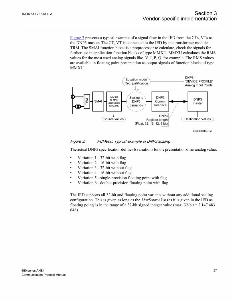
Figure 3 presents a typical example of a signal flow in the IED from the CTs, VTs tothe DNP3 master. The CT, VT is connected to the IED by the transformer moduleTRM. The SMAI function block is a preprocessor to calculate, check the signals forfurther use in application function blocks of type MMXU. MMXU calculates the RMSvalues for the most used analog signals like, V, I, P, Q, for example. The RMS valuesare available in floating point presentation as output signals of function blocks of typeMMXU.
IEC08000404.vsd
SMAIMMXU or other
application functions
DNP3master
DNP3Comm.
Interface
Scaling toDNP3
demands
Source values Destination Values
Equation modeReg. justification
DNP3 ’DEVICE PROFILE’Analog Input Points
DNP3 Register length
(Float, 32, 16, 12, 8 bit)
TRM
IEC08000404 V1 EN
Figure 3: PCM600: Typical example of DNP3 scaling
The actual DNP3 specification defines 6 variations for the presentation of an analog value:
• Variation 1 - 32-bit with flag• Variation 2 - 16-bit with flag• Variation 3 - 32-bit without flag• Variation 4 - 16-bit without flag• Variation 5 - single-precision floating point with flag• Variation 6 - double-precision floating point with flag
The IED supports all 32-bit and floating point variants without any additional scalingconfiguration. This is given as long as the MaxSourceVal (as it is given in the IED asfloating point) is in the range of a 32-bit signed integer value (max. 32-bit = 2 147 483648).
1MRK 511 257-UUS A Section 3Vendor-specific implementation
650 series ANSI 27Communication Protocol Manual
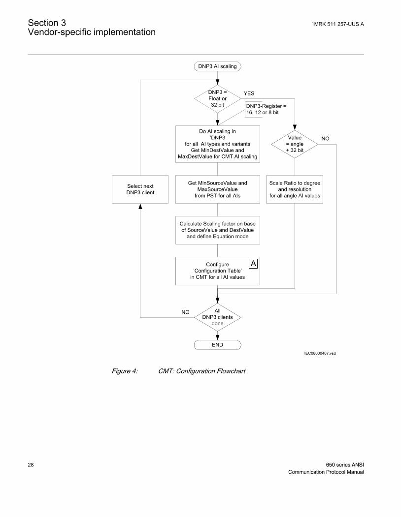
IEC08000407.vsd
DNP3 AI scaling
DNP3 =Float or 32 bit
Value = angle+ 32 bit
Do AI scaling in’DNP3
for all AI types and variantsGet MinDestValue and
MaxDestValue for CMT AI scaling
Get MinSourceValue and MaxSourceValue
from PST for all AIs
Calculate Scaling factor on base of SourceValue and DestValue
and define Equation mode
Configure’Configuration Table’
in CMT for all AI values
AllDNP3 clients
done
Scale Ratio to degree and resolution
for all angle AI values
Select nextDNP3 client
END
DNP3-Register = 16, 12 or 8 bit
YES
NO
NO
A
IEC08000407 V2 EN
Figure 4: CMT: Configuration Flowchart
Section 3 1MRK 511 257-UUS AVendor-specific implementation
28 650 series ANSICommunication Protocol Manual
3.7 DNP3 points
See the engineering manual for instructions on how to configure DNP3with PCM600.
3.7.1 Point configurationThe DNP3 point map is configurable in PCM600. All points in the IED may beremapped. In PCM600, the unmapped points in the variables list on the left may beinserted to the active point list on the right.
Point gaps may be inserted if wanted. Point gaps cannot be read by the client.
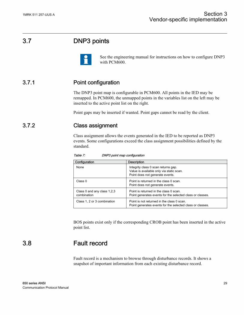
3.7.2 Class assignmentClass assignment allows the events generated in the IED to be reported as DNP3events. Some configurations exceed the class assignment possibilities defined by thestandard.
Table 7: DNP3 point map configuration
Configuration DescriptionNone Integrity class 0 scan returns gap.
Value is available only via static scan.Point does not generate events.
Class 0 Point is returned in the class 0 scan.Point does not generate events.
Class 0 and any class 1,2,3combination
Point is returned in the class 0 scan.Point generates events for the selected class or classes.
Class 1, 2 or 3 combination Point is not returned in the class 0 scan.Point generates events for the selected class or classes.
BOS points exist only if the corresponding CROB point has been inserted in the activepoint list.
3.8 Fault record
Fault record is a mechanism to browse through disturbance records. It shows asnapshot of important information from each existing disturbance record.
1MRK 511 257-UUS A Section 3Vendor-specific implementation
650 series ANSI 29Communication Protocol Manual
Fault record contains signals that provide information on the current disturbance thatthe user of the FaultRecord has selected. It provides signals that help the user to iterateand browse through the existing disturbances. All the signals that can be used to iteratethe fault records can be mapped as binary outputs in PCM600 and operated on withCROBs. All signals that provide information on the current disturbance can be mappedas analog inputs and read by the master. The DNP3 master navigates through theFaultRecord using the three signals:
• GetFirstRec fetches the oldest record in the FaultRecord.• GetNextRec fetches the next record in time in the FaultRecord relative to the
previously fetched record. If the previously fetched record is the newest, no fetchis done.
• GetPrevRec fetches the previous record in time in the FaultRecord relative to thepreviously fetched record. If the previously fetched record is the oldest, no fetch isdone.
When a new disturbance is recorded, and the outputs are mapped to one of the eventclasses, events are generated, but the navigation in the FaultRecord is not affected.Hence, when the next command is sent from the DNP3 master, the fetched position isrelative to the last fetch done; the position in the FaultRecord before the newdisturbance occurred.
The output signals provide the fault record number, which is the number of thedisturbance in the LHMI or PCM600, the number of faults in the IED, the activesetting group at the time of the disturbance recording, the trigger signal identity, thetime stamp at the trigger time as well as the fault location and the fault type. Inaddition, the magnitude, angle, fault magnitude and fault angle are provided for up to30 of the analog channels connected to the disturbance recorder, and for the last 10analog channels, the calculated value at the trigger time is provided.
Section 3 1MRK 511 257-UUS AVendor-specific implementation
30 650 series ANSICommunication Protocol Manual
Section 4 DNP3 parameters
4.1 Parameter descriptions
The DNP3 parameters for a specific IED can be accessed with PCM600 via IEDConfiguration/Communication/Station Communication/DNP3.0. There is onegeneral setting for DNP3 (Disabled/Enabled), available in function DNPGEN:1. Thisparameter must be Enabled for the other parameters to have effect. Eachcommunication channel has specific settings.
Function OPTICALPROT:1 is used to select if DNP3 or IEC60870-5-103communication protocol shall be used for the serial optical port COM05 hardwaremodule. Function RS485PROT:1 is used to select if DNP3 or IEC60870-5-103communication protocol shall be used for the RS485 serial port on COM05 hardwaremodule. When RS485 serial port is selected, also settings in function RS485GEN:1must be considered.
There are specific settings for the serial channel depending on if the serial optical orRS485 interface is used. Communication specific settings for the serial opticalinterface are available in function OPTICALDNP:1 and communication specificsettings for the RS485 interface are available in function RS485DNP:1. There arespecific settings for the master sessions, available in function MSTSERIAL:1, when amaster session occurs on the serial channel.
There are specific settings for the TCP/IP channel, available in functions CH1TCP toCH4TCP and MST1TCP to MS4TCP.
The channel blocks and the master blocks are separate but should be treated as pairsgrouped together with a number. For example, CH1TCP and MST1TCP should betreated as an entity during engineering. The reason for this division is that it isconceptually possible to have multiple masters talking on the same channel, forexample, a serial link, and it is also possible to imagine a single master switchingbetween different channels, for example, different serial links.
TCP/IP communication, CH1TCP - CH4TCP channels settingsTCPIPLisPort defines the listen port if the channel is configured for TCP/IP. Default is20000.
UDPPortAccData defines the port on which the UDP datagrams should be accepted ifthe channel is configured for networking. Default is 20000.
1MRK 511 257-UUS A Section 4DNP3 parameters
650 series ANSI 31Communication Protocol Manual

UDPPortInitNUL defines the master's destination port to which the initial NULLresponse should be sent if the channel is configured for networking. Default is 20000.
UDPPortCliMast defines the master's destination port to which responses should besent if the channel is configured for networking. If the parameter is set to 0, the portnumber is taken from the previous request. Default is 0. There are specific settings forthe master sessions if the master session occurs on the serial channel or on the TCP/IPchannels.
ApLayMaxRxSize specifies the maximum application fragment size received in octets.
ApLayMaxTxSize specifies the maximum application fragment size transmitted in octets.
UDP is not supported in this release of 650 series. Do not use "UDP-only" for setting Operation.
Master session settings for a specific communicationchannel ,MST1TCP - MST4TCPOperation determines the operation of the master session. 0 = Disabled. 1 = Enabled.
SlaveAddress defines the DNP3 address of this master session.
MasterAddress defines the DNP3 address that this master session uses forcommunication.
ValMasterAddr determines if the stack should validate the source address in receiveframes. DNP3 frames contain both a source address field and a destination addressfield. If this parameter is set to 0, the stack does not validate the source address andthus the frames whose destination address matches the configured slave session areaccepted. If this parameter is set to 1, both the source and the destination addresseshave to match before the frame is accepted.
When going down in baudrate, the size of the configuration on DNPmust be considered.
MasterIP-Addr defines the master's IP address.
MasterIPNetMsk determines the subnet mask that should be used to mask with the IPaddress.
Obj1DefVar determines the default variation for Object 1, Binary Inputs.
Obj2DefVar determines the default variation for Object 2, Binary Input Change Events.
Obj3DefVar determines the default variation for Object 3, Double Bit Inputs.
Section 4 1MRK 511 257-UUS ADNP3 parameters
32 650 series ANSICommunication Protocol Manual
Obj4DefVar determines the default variation for Object 4, Double Bit Input ChangeEvents.
Obj10DefVar determines the default variation for Object 10, Binary Output Status.
Obj20DefVar determines the default variation for Object 20, Binary Counters.
Obj22DefVar determines the default variation for Object 22, Binary Counter ChangeEvents.
Obj30DefVar determines the default variation for Object 30, Analog Inputs.
Obj32DefVar determines the default variation for Object 32, Analog Change Events.
AddrQueryEnbl determines whether to enable self-address functionality on this mastersession (slave) as specified by the DNP Technical Bulletin 2003-003. Self-AddressReservation. The master session (Slave) responds to the address 0xfffc as if it hadreceived a request for its configured address. It responds with its own address so thatthe master can automatically discover the slave address.
tApplConfTout specifies how long the slave waits for the application layerconfirmation from the master. This in combination with unsolRetryDelay orunsolOfflineRetryDelay determines how frequently an unsolicited response is resent.
ApplMultFrgRes determines if the application layer of this master session in the slaveis allowed to send multi fragment responses.
ConfMultFrag determines if application layer confirmations are requested for non-finalfragments of a multi-fragment response. Application layer confirmations are alwaysrequested for responses that contain events.
UREnable determines if unsolicited responses are allowed. If set to 0, no unsolicitedresponses are generated and requests to enable or disable unsolicited responses fail.
UREvClassMask specifies the initial or new state of the unsolicited event mask. Thismask is used to determine which event class or classes generate unsolicited responses.According to the DNP3 specification, unsolicited responses should be disabled until anEnable Unsolicited Response request is received from the master. Thus, this valueshould generally be 0. However, some masters do not generate the Enable UnsolicitedResponse message, in which case they must be enabled here. Keep the value to 0 for allother purposes.
UROfflineRetry specifies the maximum number of unsolicited retries before changingto the offline retry period. Up to 65535 retries can be specified. Set UROfflRetryDel tothe same value as URRetryDelay to define an infinite number of retries.
tURRetryDelay specifies in seconds the time to delay after an unsolicited confirmtimeout before retrying the unsolicited response.
1MRK 511 257-UUS A Section 4DNP3 parameters
650 series ANSI 33Communication Protocol Manual
tUROfflRtryDel specifies in seconds the time to delay after an unsolicited timeoutbefore retrying the unsolicited response if UROfflineRetry has been attempted. Todisable retries after UROfflineRetry, set this value to the maximum value of a stacktimer: 31 days. This limits the retries to one in every 31 days.
UREvCntThold1 If unsolicited responses are enabled, this parameter specifies themaximum number of events in class 1 to be allowed before an unsolicited response isgenerated.
tUREvBufTout1 If unsolicited responses are enabled (UREnable), this parameterspecifies the maximum amount of time in seconds before an unsolicited response isgenerated after an event in class 1 has been received.
UREvCntThold2 If unsolicited responses are enabled (UREnable), this parameterspecifies the maximum number of allowed class 2 events before an unsolicitedresponse is generated.
tUREvBufTout2 If unsolicited responses are enabled (UREnable), this parameterspecifies the maximum amount of time in seconds before an unsolicited response isgenerated after an event in class 2 has been received.
UREvCntThold3 If unsolicited responses are enabled (UREnable), this parameterspecifies the maximum number of allowed class 3 events before an unsolicitedresponse will be generated.
tUREvBufTout3 If unsolicited responses are enabled (UREnable), this parameterspecifies the maximum amount of time in seconds before an unsolicited response isgenerated after an event in class 3 has been received .
DelOldBufFull If this parameter is set to 1, the event with the earliest timeStamp isdeleted when a new event is added to the full event queue.
ExtTimeFormat 0 = LocalTime. 1 = UTC.
DNPToSetTime determines if time synch messages received for this master session(slave) are allowed to set the local time in the IED.
tSynchTimeout sets the periodicity for time requests. That is, it defines how long after asucceeded time synch message from the master, the IIN.4 bit should be set.
TsyncReqAfTout determines if the stack should start with the IIN.4 bit set.
Averag3TimeReq determines if the IED needs three time synch messages to set thetime. If set, the IIN.4 bit is high until three time synch messages are received. Theaverage of the two best messages are used to set the time.
PairedPoint enables the Object12 Close request on an even-index point to access thenext-index point.
Section 4 1MRK 511 257-UUS ADNP3 parameters
34 650 series ANSICommunication Protocol Manual
tSelectTimeout specifies the maximum amount of time that a select remains validbefore the corresponding operate is received.
The master subnet mask must not be changed unless the master gets itsIP-address dynamically assigned via, for example, DHCP. For detailssee, DNP3 TCP/IP mode
tBrokenConTout determines how long a session is active after a TCP/IP connection hasbeen broken. After that time period the master session becomes inactive and events arenot stored. If the parameter is set to 0, events are stored until the buffers overflow.
tKeepAliveT determines, in seconds, how often the DNP3 master session sends keep-alive messages. Default is 10s.
4.1.1 Serial optical and RS485 communication channel settings
RS485 specific communication channel settings, RS485GENWiremode determines the wire mode if the device is configured for RS485. RS485 is abalanced serial communication that can be used in two ways:
• Two-wire• Four-wire
A two-wire connection uses the same signal for RX and TX, and is a multidropcommunication with no dedicated master or slave. This variant requires however acontrol of the output. The four-wire connection has separate signals for RX and TXmultidrop communication with a dedicated master and the rest are slaves. No specialcontrol signal is needed in this case.
BIAS sets the bus bias to Enabled or Disabled.
Operation selection for RS485 and optical serial communication,OPTICALPROT and RS485PROTProtocolSel selects if the communication in RS485 and optical serial modes happensvia DNP or IEC 103 communication protocol. It can be Disabled via Parameter Settingtool or local HMI.
DNP3.0 for optical RS-232 and EIA-485 communication protocol,OPTICALDNP and RS485DNPBaudRate specifies the baud rate on the serial.
DLinkConfirm determines when the stack should ask for link layer confirmations.Since DNP3 supports breaking an application layer message into multiple link layer
1MRK 511 257-UUS A Section 4DNP3 parameters
650 series ANSI 35Communication Protocol Manual

frames, set to the following based on the desired operation for a specificcommunication session:
• Never - not for any frame• Sometimes - only for multiframe message fragments• Always - for all frames
tDLinkTimeout specifies the maximum amount of time to wait for a link level confirmif requested (that is, if DLinkConfirm is Enabled). Even if DLinkConfirm is set toNever, this will be used for linktest frame and request link status if they are sent.
DLinkRetries is the maximum number of link layer retries if data-link layer confirmstime up.
tRxToTxMinDel is the minimum time (in seconds) after receiving a character, beforeanother attempt to transmit a character on this channel. This is generally useful whenusing a modem or some other communication device that requires a minimum timebetween receive and transmit.
ApLayMaxRxSize specifies the maximum application fragment size received in octets.
ApLayMaxTxSize specifies the maximum application fragment size transmitted in octets.
Stopbit defines the number of stop bits for the serial port.
Parity defines the parity to use for the serial port it can be set to:
• None - no parity used• Even - even parity used• Odd - odd parity used
tRTSWarmUp configures transmitter warm-up and warm-down delay times (inmilliseconds). If warm-up is configured to non-zero then at start of the send, thetransmitter is Enabled. This means that the line is driven but the data send of the startis delayed by the warm-up delay time.
tRTSWarmDown specifies that if warm-down is configured to non zero then at end ofthe send, the transmitter deactivation is delayed by the warm-down time.
tBackOffDelay specifies that if the data send is started, a check is made if data is beingreceived at that time. If yes, a back-off timer is started and when it times out, a check ismade again to see if line is idle. If no, a new back-off timer is started. This is repeateduntil the line is idle and send can start. Line idle is determined when nothing isreceived for more than a character time. The back-off time consists of a configurablefixed time and a random time where the maximum random time is also configurable.The back-off feature is always on.
Section 4 1MRK 511 257-UUS ADNP3 parameters
36 650 series ANSICommunication Protocol Manual
tMaxRndDelBkOf specifies the configurable RS485 maximum back-off random timedelay in seconds.
HWCollisionDetect with COM05, a new collision detect feature in hardware isimplemented to improve the sensitivity for collision detection. The performance of thisfeature depends on parameters of the RS485 network as well as the protocol behaviour.It can even have negative impact on performance in some circumstances, thereforeusage of the feature should be tested and adapted for each specific installation.
HWCollisionDetect is only used for RS485 networks, thus is onlyavailable in RS485DNP function.
Master session settings for RS485 communication channel, MSTSERIALChToAssociate defines the channel, to which this master session should be associated to.
The MSTSERIAL function includes the same settings as the MS1TCPto MS4TCP functions, except the ChToAssociate setting which is usedto select either the serial optical or RS485 communication interface onCOM05 hardware module.
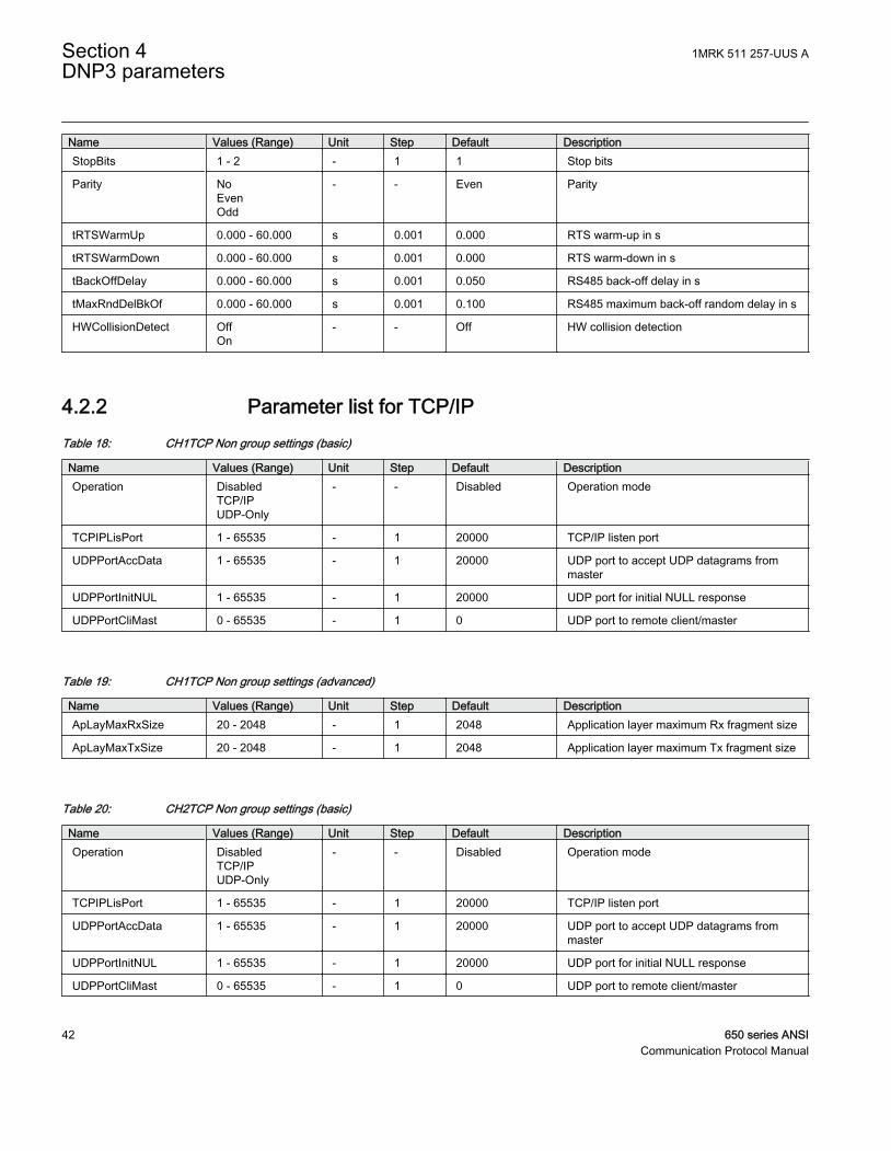
4.2 Parameter list
4.2.1 Parameter list for optical and RS485 communication channelTable 8: RS485GEN Non group settings (basic)
Name Values (Range) Unit Step Default DescriptionWireMode Four-wire
Two-wire- - Four-wire Two or four wire mode
BIAS DisabledEnabled
- - Disabled Bus biasing on/off
Table 9: RS485PROT Non group settings (basic)
Name Values (Range) Unit Step Default DescriptionProtocolSel Disabled
DNPIEC103
- - Disabled Protocol selection
1MRK 511 257-UUS A Section 4DNP3 parameters
650 series ANSI 37Communication Protocol Manual
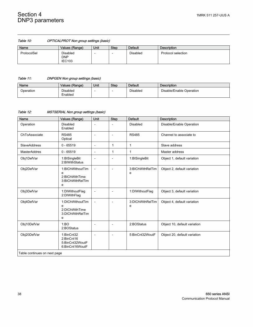
Table 10: OPTICALPROT Non group settings (basic)
Name Values (Range) Unit Step Default DescriptionProtocolSel Disabled
DNPIEC103
- - Disabled Protocol selection
Table 11: DNPGEN Non group settings (basic)
Name Values (Range) Unit Step Default DescriptionOperation Disabled
Enabled- - Disabled Disable/Enable Operation
Table 12: MSTSERIAL Non group settings (basic)
Name Values (Range) Unit Step Default DescriptionOperation Disabled
Enabled- - Disabled Disable/Enable Operation
ChToAssociate RS485Optical
- - RS485 Channel to associate to
SlaveAddress 0 - 65519 - 1 1 Slave address
MasterAddres 0 - 65519 - 1 1 Master address
Obj1DefVar 1:BISingleBit2:BIWithStatus
- - 1:BISingleBit Object 1, default variation
Obj2DefVar 1:BIChWithoutTime2:BIChWithTime3:BIChWithRelTime
- - 3:BIChWithRelTime
Object 2, default variation
Obj3DefVar 1:DIWithoutFlag2:DIWithFlag
- - 1:DIWithoutFlag Object 3, default variation
Obj4DefVar 1:DIChWithoutTime2:DIChWithTime3:DIChWithRelTime
- - 3:DIChWithRelTime
Object 4, default variation
Obj10DefVar 1:BO2:BOStatus
- - 2:BOStatus Object 10, default variation
Obj20DefVar 1:BinCnt322:BinCnt165:BinCnt32WoutF6:BinCnt16WoutF
- - 5:BinCnt32WoutF Object 20, default variation
Table continues on next page
Section 4 1MRK 511 257-UUS ADNP3 parameters
38 650 series ANSICommunication Protocol Manual
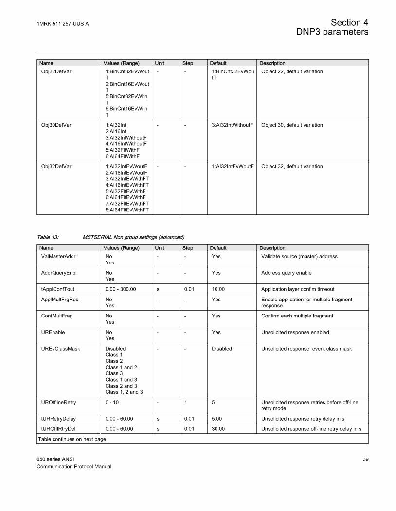
Name Values (Range) Unit Step Default DescriptionObj22DefVar 1:BinCnt32EvWout
T2:BinCnt16EvWoutT5:BinCnt32EvWithT6:BinCnt16EvWithT
- - 1:BinCnt32EvWoutT
Object 22, default variation
Obj30DefVar 1:AI32Int2:AI16Int3:AI32IntWithoutF4:AI16IntWithoutF5:AI32FltWithF6:AI64FltWithF
- - 3:AI32IntWithoutF Object 30, default variation
Obj32DefVar 1:AI32IntEvWoutF2:AI16IntEvWoutF3:AI32IntEvWithFT4:AI16IntEvWithFT5:AI32FltEvWithF6:AI64FltEvWithF7:AI32FltEvWithFT8:AI64FltEvWithFT
- - 1:AI32IntEvWoutF Object 32, default variation
Table 13: MSTSERIAL Non group settings (advanced)
Name Values (Range) Unit Step Default DescriptionValMasterAddr No
Yes- - Yes Validate source (master) address
AddrQueryEnbl NoYes
- - Yes Address query enable
tApplConfTout 0.00 - 300.00 s 0.01 10.00 Application layer confim timeout
ApplMultFrgRes NoYes
- - Yes Enable application for multiple fragmentresponse
ConfMultFrag NoYes
- - Yes Confirm each multiple fragment
UREnable NoYes
- - Yes Unsolicited response enabled
UREvClassMask DisabledClass 1Class 2Class 1 and 2Class 3Class 1 and 3Class 2 and 3Class 1, 2 and 3
- - Disabled Unsolicited response, event class mask
UROfflineRetry 0 - 10 - 1 5 Unsolicited response retries before off-lineretry mode
tURRetryDelay 0.00 - 60.00 s 0.01 5.00 Unsolicited response retry delay in s
tUROfflRtryDel 0.00 - 60.00 s 0.01 30.00 Unsolicited response off-line retry delay in s
Table continues on next page
1MRK 511 257-UUS A Section 4DNP3 parameters
650 series ANSI 39Communication Protocol Manual
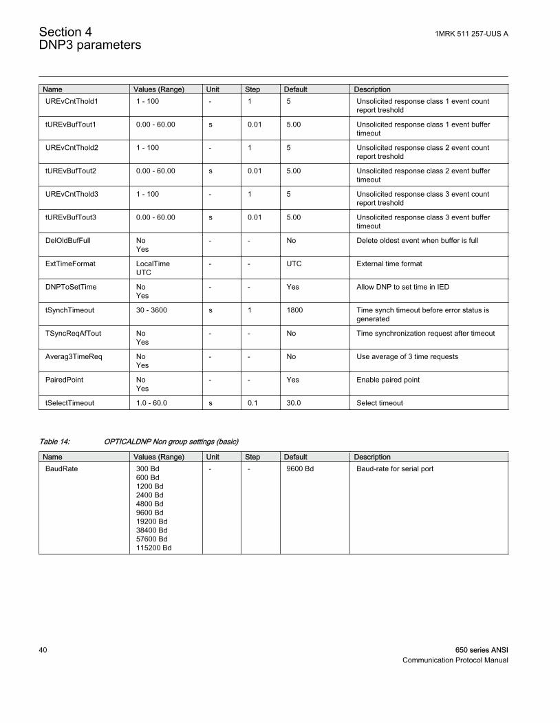
Name Values (Range) Unit Step Default DescriptionUREvCntThold1 1 - 100 - 1 5 Unsolicited response class 1 event count
report treshold
tUREvBufTout1 0.00 - 60.00 s 0.01 5.00 Unsolicited response class 1 event buffertimeout
UREvCntThold2 1 - 100 - 1 5 Unsolicited response class 2 event countreport treshold
tUREvBufTout2 0.00 - 60.00 s 0.01 5.00 Unsolicited response class 2 event buffertimeout
UREvCntThold3 1 - 100 - 1 5 Unsolicited response class 3 event countreport treshold
tUREvBufTout3 0.00 - 60.00 s 0.01 5.00 Unsolicited response class 3 event buffertimeout
DelOldBufFull NoYes
- - No Delete oldest event when buffer is full
ExtTimeFormat LocalTimeUTC
- - UTC External time format
DNPToSetTime NoYes
- - Yes Allow DNP to set time in IED
tSynchTimeout 30 - 3600 s 1 1800 Time synch timeout before error status isgenerated
TSyncReqAfTout NoYes
- - No Time synchronization request after timeout
Averag3TimeReq NoYes
- - No Use average of 3 time requests
PairedPoint NoYes
- - Yes Enable paired point
tSelectTimeout 1.0 - 60.0 s 0.1 30.0 Select timeout
Table 14: OPTICALDNP Non group settings (basic)
Name Values (Range) Unit Step Default DescriptionBaudRate 300 Bd
600 Bd1200 Bd2400 Bd4800 Bd9600 Bd19200 Bd38400 Bd57600 Bd115200 Bd
- - 9600 Bd Baud-rate for serial port
Section 4 1MRK 511 257-UUS ADNP3 parameters
40 650 series ANSICommunication Protocol Manual
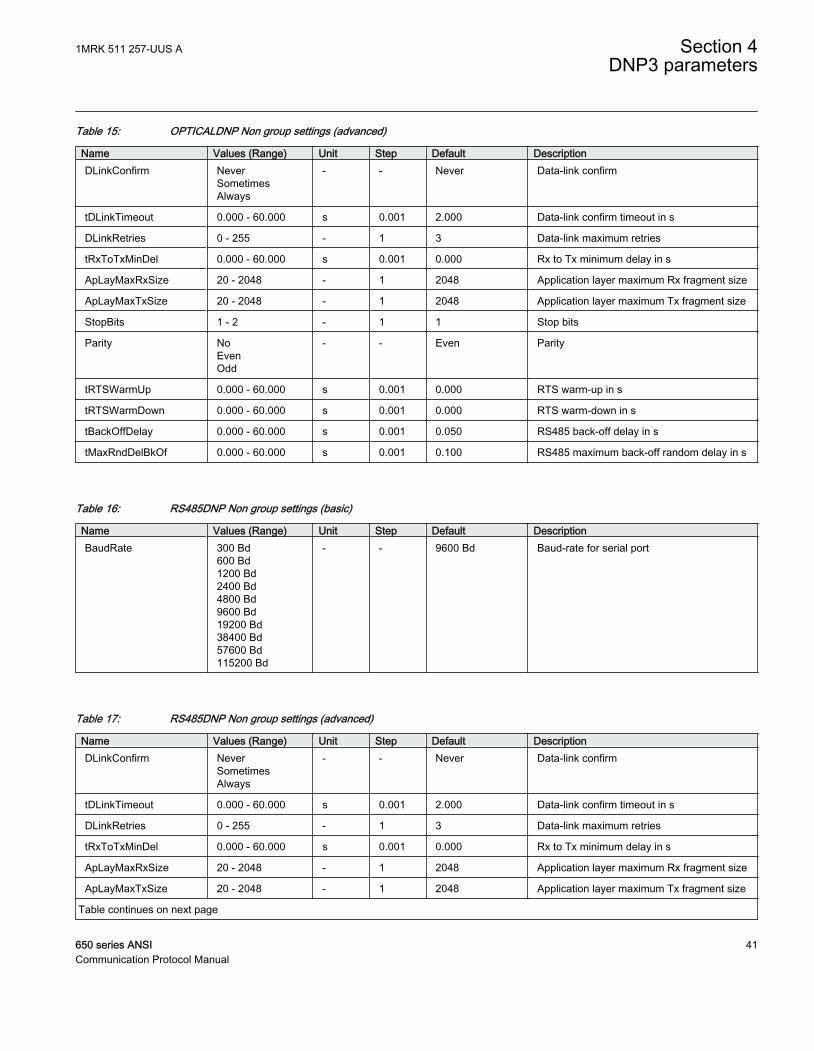
Table 15: OPTICALDNP Non group settings (advanced)
Name Values (Range) Unit Step Default DescriptionDLinkConfirm Never
SometimesAlways
- - Never Data-link confirm
tDLinkTimeout 0.000 - 60.000 s 0.001 2.000 Data-link confirm timeout in s
DLinkRetries 0 - 255 - 1 3 Data-link maximum retries
tRxToTxMinDel 0.000 - 60.000 s 0.001 0.000 Rx to Tx minimum delay in s
ApLayMaxRxSize 20 - 2048 - 1 2048 Application layer maximum Rx fragment size
ApLayMaxTxSize 20 - 2048 - 1 2048 Application layer maximum Tx fragment size
StopBits 1 - 2 - 1 1 Stop bits
Parity NoEvenOdd
- - Even Parity
tRTSWarmUp 0.000 - 60.000 s 0.001 0.000 RTS warm-up in s
tRTSWarmDown 0.000 - 60.000 s 0.001 0.000 RTS warm-down in s
tBackOffDelay 0.000 - 60.000 s 0.001 0.050 RS485 back-off delay in s
tMaxRndDelBkOf 0.000 - 60.000 s 0.001 0.100 RS485 maximum back-off random delay in s
Table 16: RS485DNP Non group settings (basic)
Name Values (Range) Unit Step Default DescriptionBaudRate 300 Bd
600 Bd1200 Bd2400 Bd4800 Bd9600 Bd19200 Bd38400 Bd57600 Bd115200 Bd
- - 9600 Bd Baud-rate for serial port
Table 17: RS485DNP Non group settings (advanced)
Name Values (Range) Unit Step Default DescriptionDLinkConfirm Never
SometimesAlways
- - Never Data-link confirm
tDLinkTimeout 0.000 - 60.000 s 0.001 2.000 Data-link confirm timeout in s
DLinkRetries 0 - 255 - 1 3 Data-link maximum retries
tRxToTxMinDel 0.000 - 60.000 s 0.001 0.000 Rx to Tx minimum delay in s
ApLayMaxRxSize 20 - 2048 - 1 2048 Application layer maximum Rx fragment size
ApLayMaxTxSize 20 - 2048 - 1 2048 Application layer maximum Tx fragment size
Table continues on next page
1MRK 511 257-UUS A Section 4DNP3 parameters
650 series ANSI 41Communication Protocol Manual
Name Values (Range) Unit Step Default DescriptionStopBits 1 - 2 - 1 1 Stop bits
Parity NoEvenOdd
- - Even Parity
tRTSWarmUp 0.000 - 60.000 s 0.001 0.000 RTS warm-up in s
tRTSWarmDown 0.000 - 60.000 s 0.001 0.000 RTS warm-down in s
tBackOffDelay 0.000 - 60.000 s 0.001 0.050 RS485 back-off delay in s
tMaxRndDelBkOf 0.000 - 60.000 s 0.001 0.100 RS485 maximum back-off random delay in s
HWCollisionDetect OffOn
- - Off HW collision detection
4.2.2 Parameter list for TCP/IPTable 18: CH1TCP Non group settings (basic)
Name Values (Range) Unit Step Default DescriptionOperation Disabled
TCP/IPUDP-Only
- - Disabled Operation mode
TCPIPLisPort 1 - 65535 - 1 20000 TCP/IP listen port
UDPPortAccData 1 - 65535 - 1 20000 UDP port to accept UDP datagrams frommaster
UDPPortInitNUL 1 - 65535 - 1 20000 UDP port for initial NULL response
UDPPortCliMast 0 - 65535 - 1 0 UDP port to remote client/master
Table 19: CH1TCP Non group settings (advanced)
Name Values (Range) Unit Step Default DescriptionApLayMaxRxSize 20 - 2048 - 1 2048 Application layer maximum Rx fragment size
ApLayMaxTxSize 20 - 2048 - 1 2048 Application layer maximum Tx fragment size
Table 20: CH2TCP Non group settings (basic)
Name Values (Range) Unit Step Default DescriptionOperation Disabled
TCP/IPUDP-Only
- - Disabled Operation mode
TCPIPLisPort 1 - 65535 - 1 20000 TCP/IP listen port
UDPPortAccData 1 - 65535 - 1 20000 UDP port to accept UDP datagrams frommaster
UDPPortInitNUL 1 - 65535 - 1 20000 UDP port for initial NULL response
UDPPortCliMast 0 - 65535 - 1 0 UDP port to remote client/master
Section 4 1MRK 511 257-UUS ADNP3 parameters
42 650 series ANSICommunication Protocol Manual

Table 21: CH2TCP Non group settings (advanced)
Name Values (Range) Unit Step Default DescriptionApLayMaxRxSize 20 - 2048 - 1 2048 Application layer maximum Rx fragment size
ApLayMaxTxSize 20 - 2048 - 1 2048 Application layer maximum Tx fragment size
Table 22: CH3TCP Non group settings (basic)
Name Values (Range) Unit Step Default DescriptionOperation Disabled
TCP/IPUDP-Only
- - Disabled Operation mode
TCPIPLisPort 1 - 65535 - 1 20000 TCP/IP listen port
UDPPortAccData 1 - 65535 - 1 20000 UDP port to accept UDP datagrams frommaster
UDPPortInitNUL 1 - 65535 - 1 20000 UDP port for initial NULL response
UDPPortCliMast 0 - 65535 - 1 0 UDP port to remote client/master
Table 23: CH3TCP Non group settings (advanced)
Name Values (Range) Unit Step Default DescriptionApLayMaxRxSize 20 - 2048 - 1 2048 Application layer maximum Rx fragment size
ApLayMaxTxSize 20 - 2048 - 1 2048 Application layer maximum Tx fragment size
Table 24: CH4TCP Non group settings (basic)
Name Values (Range) Unit Step Default DescriptionOperation Disabled
TCP/IPUDP-Only
- - Disabled Operation mode
TCPIPLisPort 1 - 65535 - 1 20000 TCP/IP listen port
UDPPortAccData 1 - 65535 - 1 20000 UDP port to accept UDP datagrams frommaster
UDPPortInitNUL 1 - 65535 - 1 20000 UDP port for initial NULL response
UDPPortCliMast 0 - 65535 - 1 0 UDP port to remote client/master
Table 25: CH4TCP Non group settings (advanced)
Name Values (Range) Unit Step Default DescriptionApLayMaxRxSize 20 - 2048 - 1 2048 Application layer maximum Rx fragment size
ApLayMaxTxSize 20 - 2048 - 1 2048 Application layer maximum Tx fragment size
1MRK 511 257-UUS A Section 4DNP3 parameters
650 series ANSI 43Communication Protocol Manual
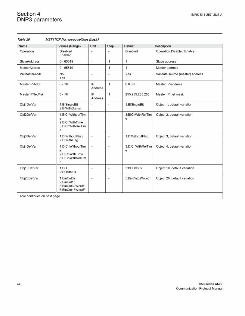
Table 26: MST1TCP Non group settings (basic)
Name Values (Range) Unit Step Default DescriptionOperation Disabled
Enabled- - Disabled Operation Disable / Enable
SlaveAddress 0 - 65519 - 1 1 Slave address
MasterAddres 0 - 65519 - 1 1 Master address
ValMasterAddr NoYes
- - Yes Validate source (master) address
MasterIP-Addr 0 - 18 IPAddress
1 0.0.0.0 Master IP-address
MasterIPNetMsk 0 - 18 IPAddress
1 255.255.255.255 Master IP net mask
Obj1DefVar 1:BISingleBit2:BIWithStatus
- - 1:BISingleBit Object 1, default variation
Obj2DefVar 1:BIChWithoutTime2:BIChWithTime3:BIChWithRelTime
- - 3:BIChWithRelTime
Object 2, default variation
Obj3DefVar 1:DIWithoutFlag2:DIWithFlag
- - 1:DIWithoutFlag Object 3, default variation
Obj4DefVar 1:DIChWithoutTime2:DIChWithTime3:DIChWithRelTime
- - 3:DIChWithRelTime
Object 4, default variation
Obj10DefVar 1:BO2:BOStatus
- - 2:BOStatus Object 10, default variation
Obj20DefVar 1:BinCnt322:BinCnt165:BinCnt32WoutF6:BinCnt16WoutF
- - 5:BinCnt32WoutF Object 20, default variation
Table continues on next page
Section 4 1MRK 511 257-UUS ADNP3 parameters
44 650 series ANSICommunication Protocol Manual
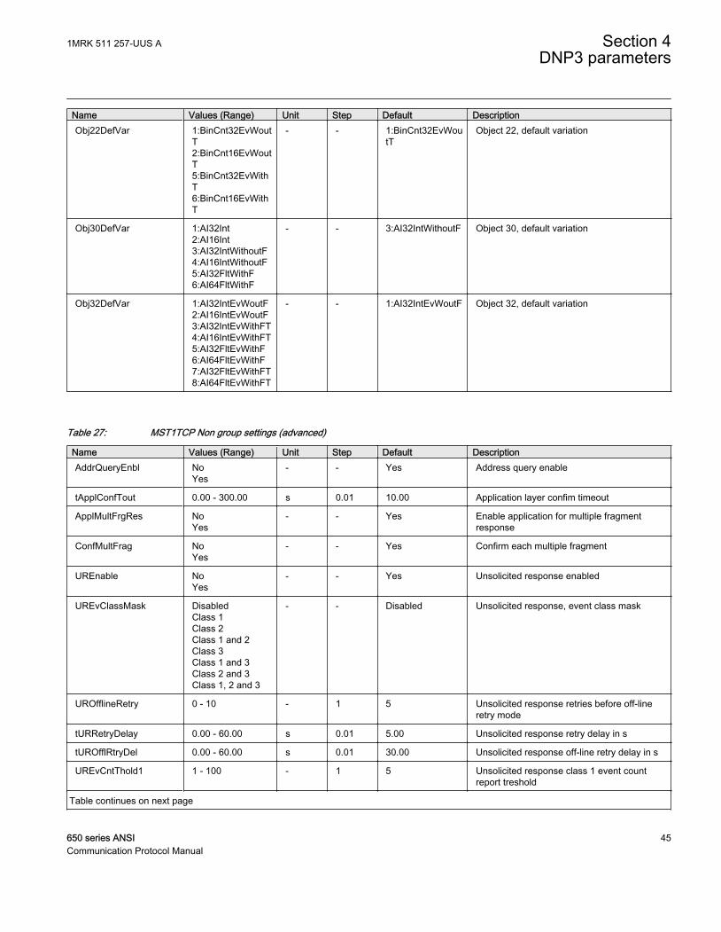
Name Values (Range) Unit Step Default DescriptionObj22DefVar 1:BinCnt32EvWout
T2:BinCnt16EvWoutT5:BinCnt32EvWithT6:BinCnt16EvWithT
- - 1:BinCnt32EvWoutT
Object 22, default variation
Obj30DefVar 1:AI32Int2:AI16Int3:AI32IntWithoutF4:AI16IntWithoutF5:AI32FltWithF6:AI64FltWithF
- - 3:AI32IntWithoutF Object 30, default variation
Obj32DefVar 1:AI32IntEvWoutF2:AI16IntEvWoutF3:AI32IntEvWithFT4:AI16IntEvWithFT5:AI32FltEvWithF6:AI64FltEvWithF7:AI32FltEvWithFT8:AI64FltEvWithFT
- - 1:AI32IntEvWoutF Object 32, default variation
Table 27: MST1TCP Non group settings (advanced)
Name Values (Range) Unit Step Default DescriptionAddrQueryEnbl No
Yes- - Yes Address query enable
tApplConfTout 0.00 - 300.00 s 0.01 10.00 Application layer confim timeout
ApplMultFrgRes NoYes
- - Yes Enable application for multiple fragmentresponse
ConfMultFrag NoYes
- - Yes Confirm each multiple fragment
UREnable NoYes
- - Yes Unsolicited response enabled
UREvClassMask DisabledClass 1Class 2Class 1 and 2Class 3Class 1 and 3Class 2 and 3Class 1, 2 and 3
- - Disabled Unsolicited response, event class mask
UROfflineRetry 0 - 10 - 1 5 Unsolicited response retries before off-lineretry mode
tURRetryDelay 0.00 - 60.00 s 0.01 5.00 Unsolicited response retry delay in s
tUROfflRtryDel 0.00 - 60.00 s 0.01 30.00 Unsolicited response off-line retry delay in s
UREvCntThold1 1 - 100 - 1 5 Unsolicited response class 1 event countreport treshold
Table continues on next page
1MRK 511 257-UUS A Section 4DNP3 parameters
650 series ANSI 45Communication Protocol Manual
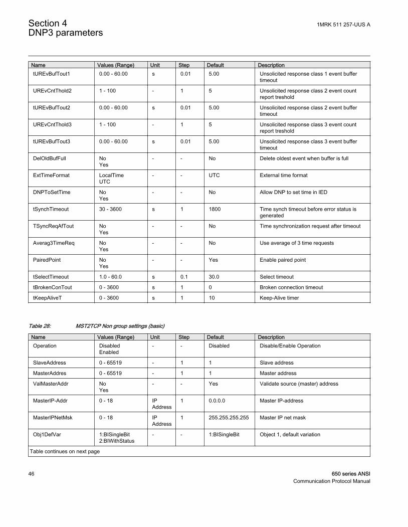
Name Values (Range) Unit Step Default DescriptiontUREvBufTout1 0.00 - 60.00 s 0.01 5.00 Unsolicited response class 1 event buffer
timeout
UREvCntThold2 1 - 100 - 1 5 Unsolicited response class 2 event countreport treshold
tUREvBufTout2 0.00 - 60.00 s 0.01 5.00 Unsolicited response class 2 event buffertimeout
UREvCntThold3 1 - 100 - 1 5 Unsolicited response class 3 event countreport treshold
tUREvBufTout3 0.00 - 60.00 s 0.01 5.00 Unsolicited response class 3 event buffertimeout
DelOldBufFull NoYes
- - No Delete oldest event when buffer is full
ExtTimeFormat LocalTimeUTC
- - UTC External time format
DNPToSetTime NoYes
- - No Allow DNP to set time in IED
tSynchTimeout 30 - 3600 s 1 1800 Time synch timeout before error status isgenerated
TSyncReqAfTout NoYes
- - No Time synchronization request after timeout
Averag3TimeReq NoYes
- - No Use average of 3 time requests
PairedPoint NoYes
- - Yes Enable paired point
tSelectTimeout 1.0 - 60.0 s 0.1 30.0 Select timeout
tBrokenConTout 0 - 3600 s 1 0 Broken connection timeout
tKeepAliveT 0 - 3600 s 1 10 Keep-Alive timer
Table 28: MST2TCP Non group settings (basic)
Name Values (Range) Unit Step Default DescriptionOperation Disabled
Enabled- - Disabled Disable/Enable Operation
SlaveAddress 0 - 65519 - 1 1 Slave address
MasterAddres 0 - 65519 - 1 1 Master address
ValMasterAddr NoYes
- - Yes Validate source (master) address
MasterIP-Addr 0 - 18 IPAddress
1 0.0.0.0 Master IP-address
MasterIPNetMsk 0 - 18 IPAddress
1 255.255.255.255 Master IP net mask
Obj1DefVar 1:BISingleBit2:BIWithStatus
- - 1:BISingleBit Object 1, default variation
Table continues on next page
Section 4 1MRK 511 257-UUS ADNP3 parameters
46 650 series ANSICommunication Protocol Manual
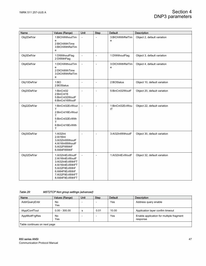
Name Values (Range) Unit Step Default DescriptionObj2DefVar 1:BIChWithoutTim
e2:BIChWithTime3:BIChWithRelTime
- - 3:BIChWithRelTime
Object 2, default variation
Obj3DefVar 1:DIWithoutFlag2:DIWithFlag
- - 1:DIWithoutFlag Object 3, default variation
Obj4DefVar 1:DIChWithoutTime2:DIChWithTime3:DIChWithRelTime
- - 3:DIChWithRelTime
Object 4, default variation
Obj10DefVar 1:BO2:BOStatus
- - 2:BOStatus Object 10, default variation
Obj20DefVar 1:BinCnt322:BinCnt165:BinCnt32WoutF6:BinCnt16WoutF
- - 5:BinCnt32WoutF Object 20, default variation
Obj22DefVar 1:BinCnt32EvWoutT2:BinCnt16EvWoutT5:BinCnt32EvWithT6:BinCnt16EvWithT
- - 1:BinCnt32EvWoutT
Object 22, default variation
Obj30DefVar 1:AI32Int2:AI16Int3:AI32IntWithoutF4:AI16IntWithoutF5:AI32FltWithF6:AI64FltWithF
- - 3:AI32IntWithoutF Object 30, default variation
Obj32DefVar 1:AI32IntEvWoutF2:AI16IntEvWoutF3:AI32IntEvWithFT4:AI16IntEvWithFT5:AI32FltEvWithF6:AI64FltEvWithF7:AI32FltEvWithFT8:AI64FltEvWithFT
- - 1:AI32IntEvWoutF Object 32, default variation
Table 29: MST2TCP Non group settings (advanced)
Name Values (Range) Unit Step Default DescriptionAddrQueryEnbl No
Yes- - Yes Address query enable
tApplConfTout 0.00 - 300.00 s 0.01 10.00 Application layer confim timeout
ApplMultFrgRes NoYes
- - Yes Enable application for multiple fragmentresponse
Table continues on next page
1MRK 511 257-UUS A Section 4DNP3 parameters
650 series ANSI 47Communication Protocol Manual
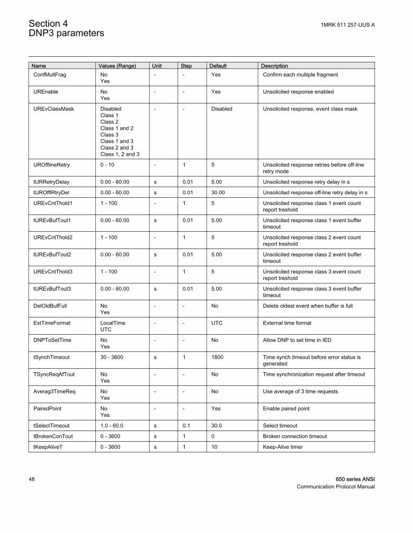
Name Values (Range) Unit Step Default DescriptionConfMultFrag No
Yes- - Yes Confirm each multiple fragment
UREnable NoYes
- - Yes Unsolicited response enabled
UREvClassMask DisabledClass 1Class 2Class 1 and 2Class 3Class 1 and 3Class 2 and 3Class 1, 2 and 3
- - Disabled Unsolicited response, event class mask
UROfflineRetry 0 - 10 - 1 5 Unsolicited response retries before off-lineretry mode
tURRetryDelay 0.00 - 60.00 s 0.01 5.00 Unsolicited response retry delay in s
tUROfflRtryDel 0.00 - 60.00 s 0.01 30.00 Unsolicited response off-line retry delay in s
UREvCntThold1 1 - 100 - 1 5 Unsolicited response class 1 event countreport treshold
tUREvBufTout1 0.00 - 60.00 s 0.01 5.00 Unsolicited response class 1 event buffertimeout
UREvCntThold2 1 - 100 - 1 5 Unsolicited response class 2 event countreport treshold
tUREvBufTout2 0.00 - 60.00 s 0.01 5.00 Unsolicited response class 2 event buffertimeout
UREvCntThold3 1 - 100 - 1 5 Unsolicited response class 3 event countreport treshold
tUREvBufTout3 0.00 - 60.00 s 0.01 5.00 Unsolicited response class 3 event buffertimeout
DelOldBufFull NoYes
- - No Delete oldest event when buffer is full
ExtTimeFormat LocalTimeUTC
- - UTC External time format
DNPToSetTime NoYes
- - No Allow DNP to set time in IED
tSynchTimeout 30 - 3600 s 1 1800 Time synch timeout before error status isgenerated
TSyncReqAfTout NoYes
- - No Time synchronization request after timeout
Averag3TimeReq NoYes
- - No Use average of 3 time requests
PairedPoint NoYes
- - Yes Enable paired point
tSelectTimeout 1.0 - 60.0 s 0.1 30.0 Select timeout
tBrokenConTout 0 - 3600 s 1 0 Broken connection timeout
tKeepAliveT 0 - 3600 s 1 10 Keep-Alive timer
Section 4 1MRK 511 257-UUS ADNP3 parameters
48 650 series ANSICommunication Protocol Manual
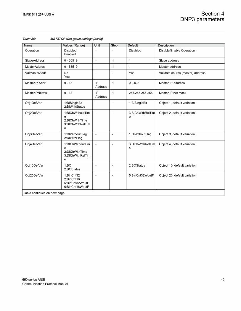
Table 30: MST3TCP Non group settings (basic)
Name Values (Range) Unit Step Default DescriptionOperation Disabled
Enabled- - Disabled Disable/Enable Operation
SlaveAddress 0 - 65519 - 1 1 Slave address
MasterAddres 0 - 65519 - 1 1 Master address
ValMasterAddr NoYes
- - Yes Validate source (master) address
MasterIP-Addr 0 - 18 IPAddress
1 0.0.0.0 Master IP-address
MasterIPNetMsk 0 - 18 IPAddress
1 255.255.255.255 Master IP net mask
Obj1DefVar 1:BISingleBit2:BIWithStatus
- - 1:BISingleBit Object 1, default variation
Obj2DefVar 1:BIChWithoutTime2:BIChWithTime3:BIChWithRelTime
- - 3:BIChWithRelTime
Object 2, default variation
Obj3DefVar 1:DIWithoutFlag2:DIWithFlag
- - 1:DIWithoutFlag Object 3, default variation
Obj4DefVar 1:DIChWithoutTime2:DIChWithTime3:DIChWithRelTime
- - 3:DIChWithRelTime
Object 4, default variation
Obj10DefVar 1:BO2:BOStatus
- - 2:BOStatus Object 10, default variation
Obj20DefVar 1:BinCnt322:BinCnt165:BinCnt32WoutF6:BinCnt16WoutF
- - 5:BinCnt32WoutF Object 20, default variation
Table continues on next page
1MRK 511 257-UUS A Section 4DNP3 parameters
650 series ANSI 49Communication Protocol Manual
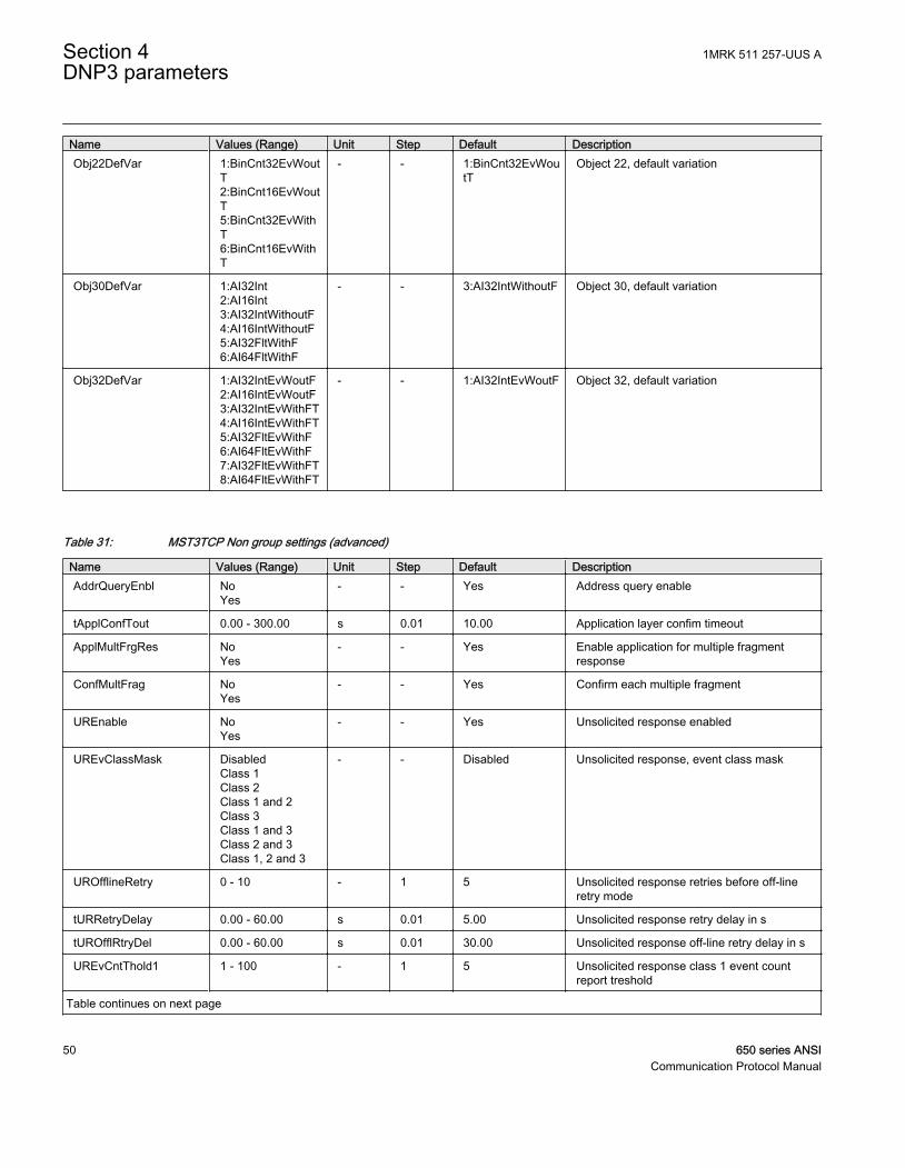
Name Values (Range) Unit Step Default DescriptionObj22DefVar 1:BinCnt32EvWout
T2:BinCnt16EvWoutT5:BinCnt32EvWithT6:BinCnt16EvWithT
- - 1:BinCnt32EvWoutT
Object 22, default variation
Obj30DefVar 1:AI32Int2:AI16Int3:AI32IntWithoutF4:AI16IntWithoutF5:AI32FltWithF6:AI64FltWithF
- - 3:AI32IntWithoutF Object 30, default variation
Obj32DefVar 1:AI32IntEvWoutF2:AI16IntEvWoutF3:AI32IntEvWithFT4:AI16IntEvWithFT5:AI32FltEvWithF6:AI64FltEvWithF7:AI32FltEvWithFT8:AI64FltEvWithFT
- - 1:AI32IntEvWoutF Object 32, default variation
Table 31: MST3TCP Non group settings (advanced)
Name Values (Range) Unit Step Default DescriptionAddrQueryEnbl No
Yes- - Yes Address query enable
tApplConfTout 0.00 - 300.00 s 0.01 10.00 Application layer confim timeout
ApplMultFrgRes NoYes
- - Yes Enable application for multiple fragmentresponse
ConfMultFrag NoYes
- - Yes Confirm each multiple fragment
UREnable NoYes
- - Yes Unsolicited response enabled
UREvClassMask DisabledClass 1Class 2Class 1 and 2Class 3Class 1 and 3Class 2 and 3Class 1, 2 and 3
- - Disabled Unsolicited response, event class mask
UROfflineRetry 0 - 10 - 1 5 Unsolicited response retries before off-lineretry mode
tURRetryDelay 0.00 - 60.00 s 0.01 5.00 Unsolicited response retry delay in s
tUROfflRtryDel 0.00 - 60.00 s 0.01 30.00 Unsolicited response off-line retry delay in s
UREvCntThold1 1 - 100 - 1 5 Unsolicited response class 1 event countreport treshold
Table continues on next page
Section 4 1MRK 511 257-UUS ADNP3 parameters
50 650 series ANSICommunication Protocol Manual
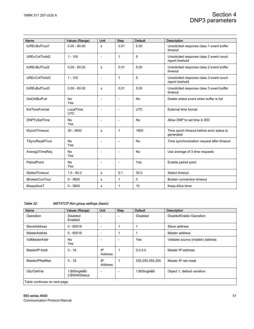
Name Values (Range) Unit Step Default DescriptiontUREvBufTout1 0.00 - 60.00 s 0.01 5.00 Unsolicited response class 1 event buffer
timeout
UREvCntThold2 1 - 100 - 1 5 Unsolicited response class 2 event countreport treshold
tUREvBufTout2 0.00 - 60.00 s 0.01 5.00 Unsolicited response class 2 event buffertimeout
UREvCntThold3 1 - 100 - 1 5 Unsolicited response class 3 event countreport treshold
tUREvBufTout3 0.00 - 60.00 s 0.01 5.00 Unsolicited response class 3 event buffertimeout
DelOldBufFull NoYes
- - No Delete oldest event when buffer is full
ExtTimeFormat LocalTimeUTC
- - UTC External time format
DNPToSetTime NoYes
- - No Allow DNP to set time in IED
tSynchTimeout 30 - 3600 s 1 1800 Time synch timeout before error status isgenerated
TSyncReqAfTout NoYes
- - No Time synchronization request after timeout
Averag3TimeReq NoYes
- - No Use average of 3 time requests
PairedPoint NoYes
- - Yes Enable paired point
tSelectTimeout 1.0 - 60.0 s 0.1 30.0 Select timeout
tBrokenConTout 0 - 3600 s 1 0 Broken connection timeout
tKeepAliveT 0 - 3600 s 1 10 Keep-Alive timer
Table 32: MST4TCP Non group settings (basic)
Name Values (Range) Unit Step Default DescriptionOperation Disabled
Enabled- - Disabled Disable/Enable Operation
SlaveAddress 0 - 65519 - 1 1 Slave address
MasterAddres 0 - 65519 - 1 1 Master address
ValMasterAddr NoYes
- - Yes Validate source (master) address
MasterIP-Addr 0 - 18 IPAddress
1 0.0.0.0 Master IP-address
MasterIPNetMsk 0 - 18 IPAddress
1 255.255.255.255 Master IP net mask
Obj1DefVar 1:BISingleBit2:BIWithStatus
- - 1:BISingleBit Object 1, default variation
Table continues on next page
1MRK 511 257-UUS A Section 4DNP3 parameters
650 series ANSI 51Communication Protocol Manual
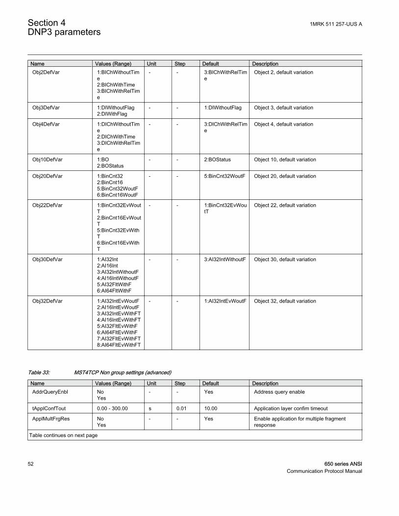
Name Values (Range) Unit Step Default DescriptionObj2DefVar 1:BIChWithoutTim
e2:BIChWithTime3:BIChWithRelTime
- - 3:BIChWithRelTime
Object 2, default variation
Obj3DefVar 1:DIWithoutFlag2:DIWithFlag
- - 1:DIWithoutFlag Object 3, default variation
Obj4DefVar 1:DIChWithoutTime2:DIChWithTime3:DIChWithRelTime
- - 3:DIChWithRelTime
Object 4, default variation
Obj10DefVar 1:BO2:BOStatus
- - 2:BOStatus Object 10, default variation
Obj20DefVar 1:BinCnt322:BinCnt165:BinCnt32WoutF6:BinCnt16WoutF
- - 5:BinCnt32WoutF Object 20, default variation
Obj22DefVar 1:BinCnt32EvWoutT2:BinCnt16EvWoutT5:BinCnt32EvWithT6:BinCnt16EvWithT
- - 1:BinCnt32EvWoutT
Object 22, default variation
Obj30DefVar 1:AI32Int2:AI16Int3:AI32IntWithoutF4:AI16IntWithoutF5:AI32FltWithF6:AI64FltWithF
- - 3:AI32IntWithoutF Object 30, default variation
Obj32DefVar 1:AI32IntEvWoutF2:AI16IntEvWoutF3:AI32IntEvWithFT4:AI16IntEvWithFT5:AI32FltEvWithF6:AI64FltEvWithF7:AI32FltEvWithFT8:AI64FltEvWithFT
- - 1:AI32IntEvWoutF Object 32, default variation
Table 33: MST4TCP Non group settings (advanced)
Name Values (Range) Unit Step Default DescriptionAddrQueryEnbl No
Yes- - Yes Address query enable
tApplConfTout 0.00 - 300.00 s 0.01 10.00 Application layer confim timeout
ApplMultFrgRes NoYes
- - Yes Enable application for multiple fragmentresponse
Table continues on next page
Section 4 1MRK 511 257-UUS ADNP3 parameters
52 650 series ANSICommunication Protocol Manual
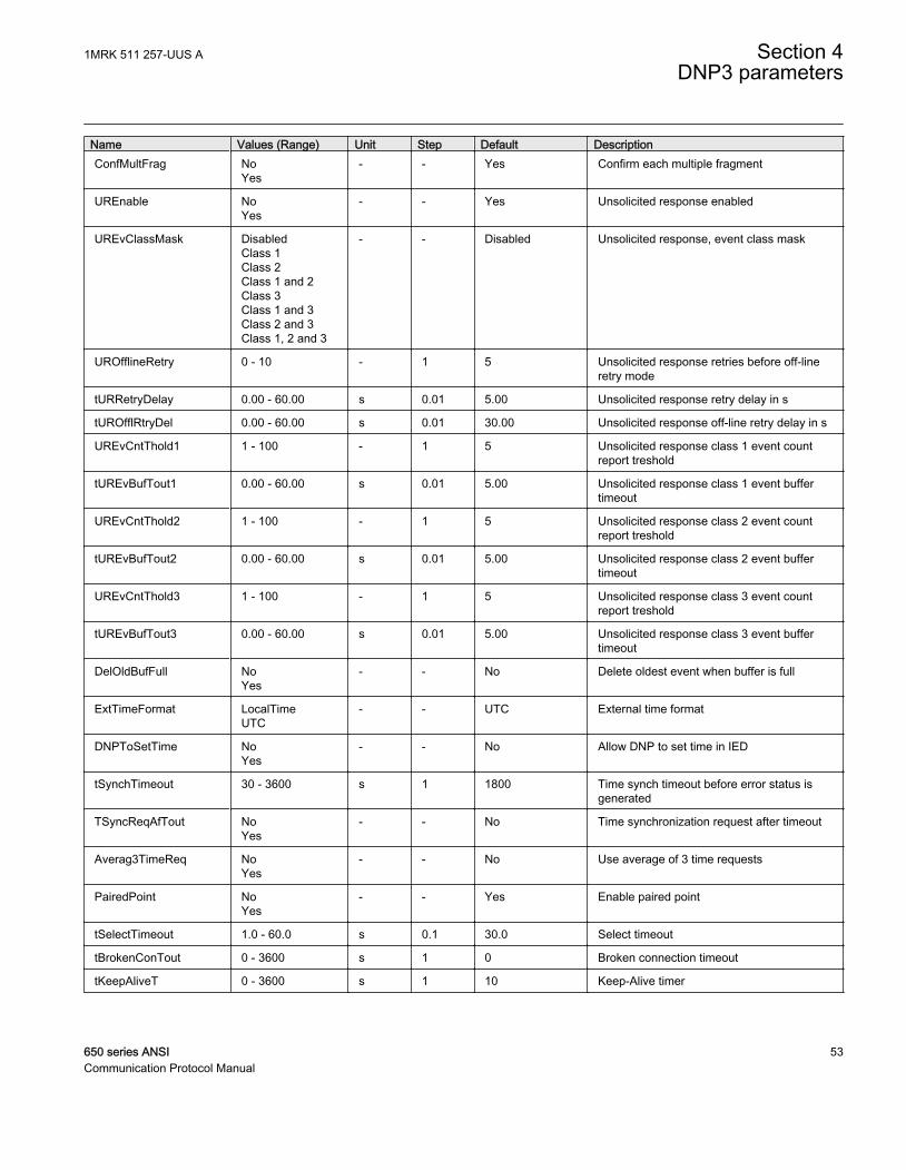
Name Values (Range) Unit Step Default DescriptionConfMultFrag No
Yes- - Yes Confirm each multiple fragment
UREnable NoYes
- - Yes Unsolicited response enabled
UREvClassMask DisabledClass 1Class 2Class 1 and 2Class 3Class 1 and 3Class 2 and 3Class 1, 2 and 3
- - Disabled Unsolicited response, event class mask
UROfflineRetry 0 - 10 - 1 5 Unsolicited response retries before off-lineretry mode
tURRetryDelay 0.00 - 60.00 s 0.01 5.00 Unsolicited response retry delay in s
tUROfflRtryDel 0.00 - 60.00 s 0.01 30.00 Unsolicited response off-line retry delay in s
UREvCntThold1 1 - 100 - 1 5 Unsolicited response class 1 event countreport treshold
tUREvBufTout1 0.00 - 60.00 s 0.01 5.00 Unsolicited response class 1 event buffertimeout
UREvCntThold2 1 - 100 - 1 5 Unsolicited response class 2 event countreport treshold
tUREvBufTout2 0.00 - 60.00 s 0.01 5.00 Unsolicited response class 2 event buffertimeout
UREvCntThold3 1 - 100 - 1 5 Unsolicited response class 3 event countreport treshold
tUREvBufTout3 0.00 - 60.00 s 0.01 5.00 Unsolicited response class 3 event buffertimeout
DelOldBufFull NoYes
- - No Delete oldest event when buffer is full
ExtTimeFormat LocalTimeUTC
- - UTC External time format
DNPToSetTime NoYes
- - No Allow DNP to set time in IED
tSynchTimeout 30 - 3600 s 1 1800 Time synch timeout before error status isgenerated
TSyncReqAfTout NoYes
- - No Time synchronization request after timeout
Averag3TimeReq NoYes
- - No Use average of 3 time requests
PairedPoint NoYes
- - Yes Enable paired point
tSelectTimeout 1.0 - 60.0 s 0.1 30.0 Select timeout
tBrokenConTout 0 - 3600 s 1 0 Broken connection timeout
tKeepAliveT 0 - 3600 s 1 10 Keep-Alive timer
1MRK 511 257-UUS A Section 4DNP3 parameters
650 series ANSI 53Communication Protocol Manual

Section 4 1MRK 511 257-UUS ADNP3 parameters
54 650 series ANSICommunication Protocol Manual

Section 5 Glossary
AC Alternating current
ACT Application configuration tool within PCM600
A/D converter Analog-to-digital converter
ADBS Amplitude deadband supervision
AI Analog input
ANSI American National Standards Institute
AR Autoreclosing
ASCT Auxiliary summation current transformer
ASD Adaptive signal detection
AWG American Wire Gauge standard
BI Binary input
BOS Binary outputs status
BR External bistable relay
BS British Standards
CAN Controller Area Network. ISO standard (ISO 11898) for serialcommunication
CB Circuit breaker
CCITT Consultative Committee for International Telegraph andTelephony. A United Nations-sponsored standards body withinthe International Telecommunications Union.
CCVT Capacitive Coupled Voltage Transformer
Class C Protection Current Transformer class as per IEEE/ ANSI
CMPPS Combined megapulses per second
CMT Communication Management tool in PCM600
CO cycle Close-open cycle
Codirectional Way of transmitting G.703 over a balanced line. Involves twotwisted pairs making it possible to transmit information in bothdirections
1MRK 511 257-UUS A Section 5Glossary
650 series ANSI 55Communication Protocol Manual
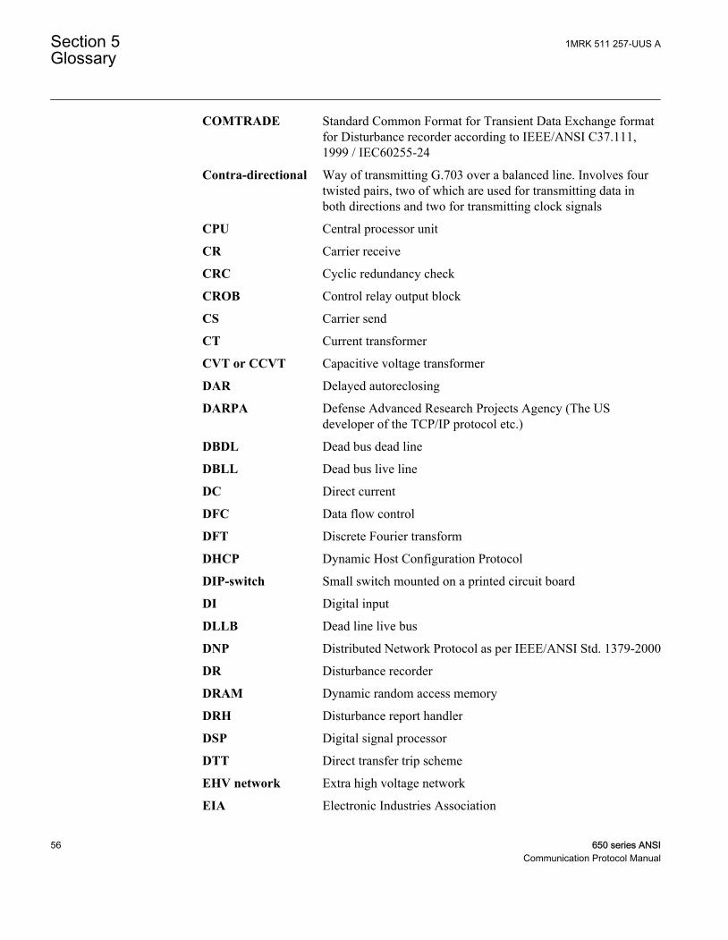
COMTRADE Standard Common Format for Transient Data Exchange formatfor Disturbance recorder according to IEEE/ANSI C37.111,1999 / IEC60255-24
Contra-directional Way of transmitting G.703 over a balanced line. Involves fourtwisted pairs, two of which are used for transmitting data inboth directions and two for transmitting clock signals
CPU Central processor unit
CR Carrier receive
CRC Cyclic redundancy check
CROB Control relay output block
CS Carrier send
CT Current transformer
CVT or CCVT Capacitive voltage transformer
DAR Delayed autoreclosing
DARPA Defense Advanced Research Projects Agency (The USdeveloper of the TCP/IP protocol etc.)
DBDL Dead bus dead line
DBLL Dead bus live line
DC Direct current
DFC Data flow control
DFT Discrete Fourier transform
DHCP Dynamic Host Configuration Protocol
DIP-switch Small switch mounted on a printed circuit board
DI Digital input
DLLB Dead line live bus
DNP Distributed Network Protocol as per IEEE/ANSI Std. 1379-2000
DR Disturbance recorder
DRAM Dynamic random access memory
DRH Disturbance report handler
DSP Digital signal processor
DTT Direct transfer trip scheme
EHV network Extra high voltage network
EIA Electronic Industries Association
Section 5 1MRK 511 257-UUS AGlossary
56 650 series ANSICommunication Protocol Manual
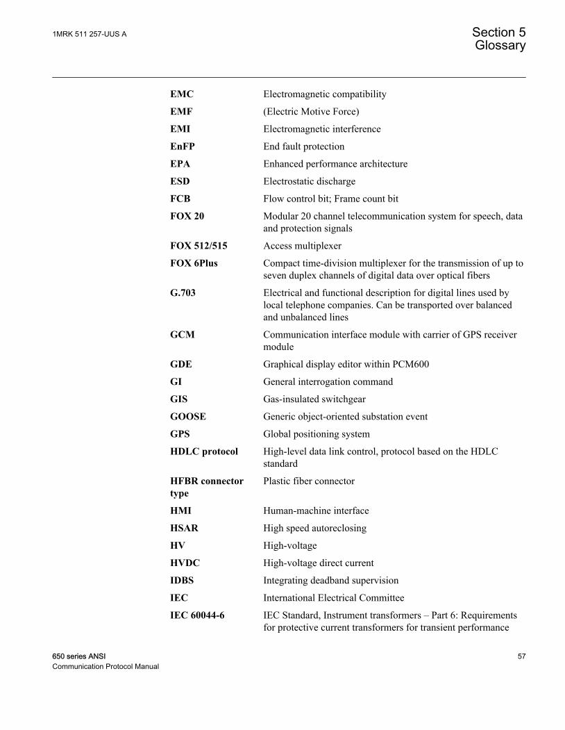
EMC Electromagnetic compatibility
EMF (Electric Motive Force)
EMI Electromagnetic interference
EnFP End fault protection
EPA Enhanced performance architecture
ESD Electrostatic discharge
FCB Flow control bit; Frame count bit
FOX 20 Modular 20 channel telecommunication system for speech, dataand protection signals
FOX 512/515 Access multiplexer
FOX 6Plus Compact time-division multiplexer for the transmission of up toseven duplex channels of digital data over optical fibers
G.703 Electrical and functional description for digital lines used bylocal telephone companies. Can be transported over balancedand unbalanced lines
GCM Communication interface module with carrier of GPS receivermodule
GDE Graphical display editor within PCM600
GI General interrogation command
GIS Gas-insulated switchgear
GOOSE Generic object-oriented substation event
GPS Global positioning system
HDLC protocol High-level data link control, protocol based on the HDLCstandard
HFBR connectortype
Plastic fiber connector
HMI Human-machine interface
HSAR High speed autoreclosing
HV High-voltage
HVDC High-voltage direct current
IDBS Integrating deadband supervision
IEC International Electrical Committee
IEC 60044-6 IEC Standard, Instrument transformers – Part 6: Requirementsfor protective current transformers for transient performance
1MRK 511 257-UUS A Section 5Glossary
650 series ANSI 57Communication Protocol Manual
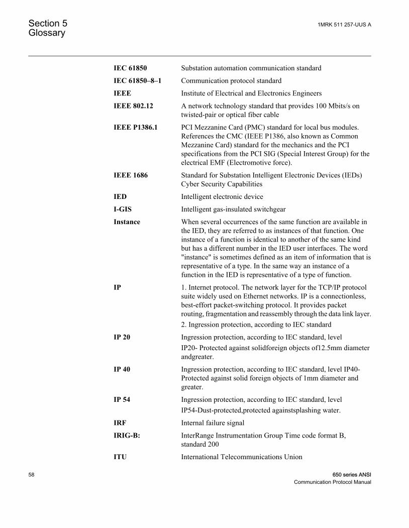
IEC 61850 Substation automation communication standard
IEC 61850–8–1 Communication protocol standard
IEEE Institute of Electrical and Electronics Engineers
IEEE 802.12 A network technology standard that provides 100 Mbits/s ontwisted-pair or optical fiber cable
IEEE P1386.1 PCI Mezzanine Card (PMC) standard for local bus modules.References the CMC (IEEE P1386, also known as CommonMezzanine Card) standard for the mechanics and the PCIspecifications from the PCI SIG (Special Interest Group) for theelectrical EMF (Electromotive force).
IEEE 1686 Standard for Substation Intelligent Electronic Devices (IEDs)Cyber Security Capabilities
IED Intelligent electronic device
I-GIS Intelligent gas-insulated switchgear
Instance When several occurrences of the same function are available inthe IED, they are referred to as instances of that function. Oneinstance of a function is identical to another of the same kindbut has a different number in the IED user interfaces. The word"instance" is sometimes defined as an item of information that isrepresentative of a type. In the same way an instance of afunction in the IED is representative of a type of function.
IP 1. Internet protocol. The network layer for the TCP/IP protocolsuite widely used on Ethernet networks. IP is a connectionless,best-effort packet-switching protocol. It provides packetrouting, fragmentation and reassembly through the data link layer.2. Ingression protection, according to IEC standard
IP 20 Ingression protection, according to IEC standard, levelIP20- Protected against solidforeign objects of12.5mm diameterandgreater.
IP 40 Ingression protection, according to IEC standard, level IP40-Protected against solid foreign objects of 1mm diameter andgreater.
IP 54 Ingression protection, according to IEC standard, levelIP54-Dust-protected,protected againstsplashing water.
IRF Internal failure signal
IRIG-B: InterRange Instrumentation Group Time code format B,standard 200
ITU International Telecommunications Union
Section 5 1MRK 511 257-UUS AGlossary
58 650 series ANSICommunication Protocol Manual
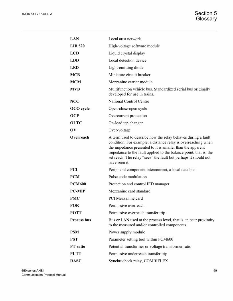
LAN Local area network
LIB 520 High-voltage software module
LCD Liquid crystal display
LDD Local detection device
LED Light-emitting diode
MCB Miniature circuit breaker
MCM Mezzanine carrier module
MVB Multifunction vehicle bus. Standardized serial bus originallydeveloped for use in trains.
NCC National Control Centre
OCO cycle Open-close-open cycle
OCP Overcurrent protection
OLTC On-load tap changer
OV Over-voltage
Overreach A term used to describe how the relay behaves during a faultcondition. For example, a distance relay is overreaching whenthe impedance presented to it is smaller than the apparentimpedance to the fault applied to the balance point, that is, theset reach. The relay “sees” the fault but perhaps it should nothave seen it.
PCI Peripheral component interconnect, a local data bus
PCM Pulse code modulation
PCM600 Protection and control IED manager
PC-MIP Mezzanine card standard
PMC PCI Mezzanine card
POR Permissive overreach
POTT Permissive overreach transfer trip
Process bus Bus or LAN used at the process level, that is, in near proximityto the measured and/or controlled components
PSM Power supply module
PST Parameter setting tool within PCM600
PT ratio Potential transformer or voltage transformer ratio
PUTT Permissive underreach transfer trip
RASC Synchrocheck relay, COMBIFLEX
1MRK 511 257-UUS A Section 5Glossary
650 series ANSI 59Communication Protocol Manual
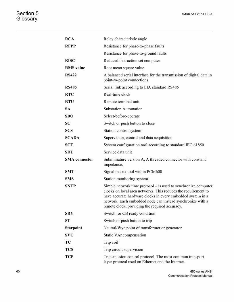
RCA Relay characteristic angle
RFPP Resistance for phase-to-phase faults
Resistance for phase-to-ground faults
RISC Reduced instruction set computer
RMS value Root mean square value
RS422 A balanced serial interface for the transmission of digital data inpoint-to-point connections
RS485 Serial link according to EIA standard RS485
RTC Real-time clock
RTU Remote terminal unit
SA Substation Automation
SBO Select-before-operate
SC Switch or push button to close
SCS Station control system
SCADA Supervision, control and data acquisition
SCT System configuration tool according to standard IEC 61850
SDU Service data unit
SMA connector Subminiature version A, A threaded connector with constantimpedance.
SMT Signal matrix tool within PCM600
SMS Station monitoring system
SNTP Simple network time protocol – is used to synchronize computerclocks on local area networks. This reduces the requirement tohave accurate hardware clocks in every embedded system in anetwork. Each embedded node can instead synchronize with aremote clock, providing the required accuracy.
SRY Switch for CB ready condition
ST Switch or push button to trip
Starpoint Neutral/Wye point of transformer or generator
SVC Static VAr compensation
TC Trip coil
TCS Trip circuit supervision
TCP Transmission control protocol. The most common transportlayer protocol used on Ethernet and the Internet.
Section 5 1MRK 511 257-UUS AGlossary
60 650 series ANSICommunication Protocol Manual
TCP/IP Transmission control protocol over Internet Protocol. The defacto standard Ethernet protocols incorporated into 4.2BSDUnix. TCP/IP was developed by DARPA for Internet workingand encompasses both network layer and transport layerprotocols. While TCP and IP specify two protocols at specificprotocol layers, TCP/IP is often used to refer to the entire USDepartment of Defense protocol suite based upon these,including Telnet, FTP, UDP and RDP.
TNC connector Threaded Neill-Concelman, a threaded constant impedanceversion of a BNC connector
TPZ, TPY, TPX,TPS
Current transformer class according to IEC
UMT User management tool
Underreach A term used to describe how the relay behaves during a faultcondition. For example, a distance relay is underreaching whenthe impedance presented to it is greater than the apparentimpedance to the fault applied to the balance point, that is, theset reach. The relay does not “see” the fault but perhaps itshould have seen it. See also Overreach.
UTC Coordinated Universal Time. A coordinated time scale,maintained by the Bureau International des Poids et Mesures(BIPM), which forms the basis of a coordinated disseminationof standard frequencies and time signals. UTC is derived fromInternational Atomic Time (TAI) by the addition of a wholenumber of "leap seconds" to synchronize it with Universal Time1 (UT1), thus allowing for the eccentricity of the Earth's orbit,the rotational axis tilt (23.5 degrees), but still showing theEarth's irregular rotation, on which UT1 is based. TheCoordinated Universal Time is expressed using a 24-hour clock,and uses the Gregorian calendar. It is used for aeroplane andship navigation, where it is also sometimes known by themilitary name, "Zulu time." "Zulu" in the phonetic alphabetstands for "Z", which stands for longitude zero.
UV Undervoltage
WEI Weak end infeed logic
VT Voltage transformer
X.21 A digital signalling interface primarily used for telecomequipment
3IO Three times zero-sequence current. Often referred to as theresidual or the -fault current
1MRK 511 257-UUS A Section 5Glossary
650 series ANSI 61Communication Protocol Manual

3VO Three times the zero sequence voltage. Often referred to as theresidual voltage or the neutral point voltage
Section 5 1MRK 511 257-UUS AGlossary
62 650 series ANSICommunication Protocol Manual

63

Contact us
ABB Inc.1021 Main Campus DriveRaleigh, NC 27606, USAPhone Toll Free: 1-800-HELP-365,menu option #8
ABB Inc.3450 Harvester RoadBurlington, ON L7N 3W5, CanadaPhone Toll Free: 1-800-HELP-365,menu option #8
ABB Mexico S.A. de C.V.Paseo de las Americas No. 31 LomasVerdes 3a secc.53125, Naucalpan, Estado De Mexico,MEXICOPhone (+1) 440-585-7804, menuoption #8
1MR
K 5
11 2
57-U
US
A©
Cop
yrig
ht 2
012
AB
B. A
ll rig
hts
rese
rved
.