communication protocol manual - abb group · communication protocol manual, lon 1mrk 511 378-uen...
TRANSCRIPT
— RELION® 650 SERIES
IEC 61850 Edition 2, 650 series Version 2.1 Communication protocol manual

Document ID: 1MRK 511 376-UENIssued: March 2019
Revision: AProduct version: 2.1
© Copyright 2016 ABB. All rights reserved

Copyright
This document and parts thereof must not be reproduced or copied without writtenpermission from ABB, and the contents thereof must not be imparted to a third party, norused for any unauthorized purpose.
The software and hardware described in this document is furnished under a license and maybe used or disclosed only in accordance with the terms of such license.
This product includes software developed by the OpenSSL Project for use in the OpenSSLToolkit. (http://www.openssl.org/) This product includes cryptographic software written/developed by: Eric Young ([email protected]) and Tim Hudson ([email protected]).
Trademarks
ABB and Relion are registered trademarks of the ABB Group. All other brand or product namesmentioned in this document may be trademarks or registered trademarks of their respectiveholders.
Warranty
Please inquire about the terms of warranty from your nearest ABB representative.

Disclaimer
The data, examples and diagrams in this manual are included solely for the concept or productdescription and are not to be deemed as a statement of guaranteed properties. All personsresponsible for applying the equipment addressed in this manual must satisfy themselves thateach intended application is suitable and acceptable, including that any applicable safety orother operational requirements are complied with. In particular, any risks in applications wherea system failure and/or product failure would create a risk for harm to property or persons(including but not limited to personal injuries or death) shall be the sole responsibility of theperson or entity applying the equipment, and those so responsible are hereby requested toensure that all measures are taken to exclude or mitigate such risks.
This document has been carefully checked by ABB but deviations cannot be completely ruledout. In case any errors are detected, the reader is kindly requested to notify the manufacturer.Other than under explicit contractual commitments, in no event shall ABB be responsible orliable for any loss or damage resulting from the use of this manual or the application of theequipment.

Conformity
This product complies with the directive of the Council of the European Communities on theapproximation of the laws of the Member States relating to electromagnetic compatibility(EMC Directive 2004/108/EC) and concerning electrical equipment for use within specifiedvoltage limits (Low-voltage directive 2006/95/EC). This conformity is the result of testsconducted by ABB in accordance with the product standard EN 60255-26 for the EMC directive,and with the product standards EN 60255-1 and EN 60255-27 for the low voltage directive. Theproduct is designed in accordance with the international standards of the IEC 60255 series.
Table of contents
Section 1 Introduction.........................................................................................................31.1 This manual......................................................................................................................................... 31.2 Intended audience............................................................................................................................. 31.3 Product documentation................................................................................................................... 41.3.1 Product documentation set........................................................................................................ 41.3.2 Document revision history...........................................................................................................51.3.3 Related documents....................................................................................................................... 51.4 Document symbols and conventions.............................................................................................71.4.1 Symbols............................................................................................................................................71.4.2 Document conventions.................................................................................................................71.5 IEC 61850 edition 1 / edition 2 mapping....................................................................................... 8
Section 2 Introduction to IEC 61850................................................................................112.1 Overview............................................................................................................................................. 112.1.1 Related documentation to IEC 61850...................................................................................... 12
Section 3 Substation Configuration description Language (SCL).............................. 153.1 The substation section................................................................................................................... 163.2 The communication section...........................................................................................................163.3 The IED section................................................................................................................................. 173.4 Tool concept......................................................................................................................................193.5 Engineering concept in IEC 61850-6............................................................................................ 20
Section 4 Communication profile.................................................................................... 21
Section 5 Supported services...........................................................................................23
Section 6 Data sets and control blocks.......................................................................... 296.1 Data sets............................................................................................................................................296.2 Report control block (URCB/BRCB)............................................................................................. 306.3 GOOSE Control Blocks (GoCB)...................................................................................................... 33
Section 7 Logical node data model..................................................................................357.1 Common data objects in each logical node............................................................................... 357.2 IEC 61850 data model description Edition 2.............................................................................. 367.2.1 Using the online help file............................................................................................................367.2.2 DO presence condition description......................................................................................... 37
Section 8 Flexible product naming.................................................................................. 398.1 Introduction...................................................................................................................................... 398.1.1 Mapping example........................................................................................................................ 398.1.2 Mapping possibilities and requirements............................................................................... 40
Section 9 Glossary............................................................................................................. 43
Table of contents
1Communication protocol manual

9.1 Glossary............................................................................................................................................. 43
Table of contents
2Communication protocol manual
Section 1 Introduction
1.1 This manualGUID-AB423A30-13C2-46AF-B7FE-A73BB425EB5F v19
The communication protocol manual describes the communication protocols supported bythe IED. The manual concentrates on the vendor-specific implementations.
1.2 Intended audienceGUID-C9B8127F-5748-4BEA-9E4F-CC762FE28A3A v10
This manual addresses the communication system engineer or system integrator responsiblefor pre-engineering and engineering for communication setup in a substation from an IEDperspective.
The system engineer or system integrator must have a basic knowledge of communication inprotection and control systems and thorough knowledge of the specific communicationprotocol.
1MRK 511 376-UEN A Section 1Introduction
3Communication protocol manual
1.3 Product documentation
1.3.1 Product documentation setGUID-3AA69EA6-F1D8-47C6-A8E6-562F29C67172 v15
IEC07000220-4-en.vsd
Plan
ning
& p
urch
ase
Engi
neer
ing
Inst
allin
g
Com
mis
sion
ing
Ope
ratio
n
Mai
nten
ance
Dec
omm
issi
onin
gD
eins
tallin
g &
disp
osal
Application manual
Operation manual
Installation manual
Engineering manual
Communication protocol manual
Cyber security deployment guideline
Technical manual
Commissioning manual
IEC07000220 V4 EN-US
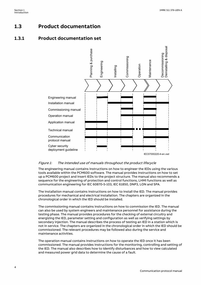
Figure 1: The intended use of manuals throughout the product lifecycle
The engineering manual contains instructions on how to engineer the IEDs using the varioustools available within the PCM600 software. The manual provides instructions on how to setup a PCM600 project and insert IEDs to the project structure. The manual also recommends asequence for the engineering of protection and control functions, LHMI functions as well ascommunication engineering for IEC 60870-5-103, IEC 61850, DNP3, LON and SPA.
The installation manual contains instructions on how to install the IED. The manual providesprocedures for mechanical and electrical installation. The chapters are organized in thechronological order in which the IED should be installed.
The commissioning manual contains instructions on how to commission the IED. The manualcan also be used by system engineers and maintenance personnel for assistance during thetesting phase. The manual provides procedures for the checking of external circuitry andenergizing the IED, parameter setting and configuration as well as verifying settings bysecondary injection. The manual describes the process of testing an IED in a station which isnot in service. The chapters are organized in the chronological order in which the IED should becommissioned. The relevant procedures may be followed also during the service andmaintenance activities.
The operation manual contains instructions on how to operate the IED once it has beencommissioned. The manual provides instructions for the monitoring, controlling and setting ofthe IED. The manual also describes how to identify disturbances and how to view calculatedand measured power grid data to determine the cause of a fault.
Section 1 1MRK 511 376-UEN AIntroduction
4Communication protocol manual
The application manual contains application descriptions and setting guidelines sorted perfunction. The manual can be used to find out when and for what purpose a typical protectionfunction can be used. The manual can also provide assistance for calculating settings.
The technical manual contains operation principle descriptions, and lists function blocks, logicdiagrams, input and output signals, setting parameters and technical data, sorted perfunction. The manual can be used as a technical reference during the engineering phase,installation and commissioning phase, and during normal service.
The communication protocol manual describes the communication protocols supported bythe IED. The manual concentrates on the vendor-specific implementations.
The point list manual describes the outlook and properties of the data points specific to theIED. The manual should be used in conjunction with the corresponding communicationprotocol manual.
The cyber security deployment guideline describes the process for handling cyber securitywhen communicating with the IED. Certification, Authorization with role based access control,and product engineering for cyber security related events are described and sorted byfunction. The guideline can be used as a technical reference during the engineering phase,installation and commissioning phase, and during normal service.
1.3.2 Document revision historyGUID-C8027F8A-D3CB-41C1-B078-F9E59BB73A6C v2.1.1
Document revision/date History
January 2016 First Release
March 2019 Maintenance Release
1.3.3 Related documentsGUID-94E8A5CA-BE1B-45AF-81E7-5A41D34EE112 v4
Documents related to REB650 Document numbers
Application manual 1MRK 505 359-UEN
Commissioning manual 1MRK 505 361-UEN
Product guide 1MRK 505 362-BEN
Technical manual 1MRK 505 360-UEN
Type test certificate 1MRK 505 362-TEN
Documents related to REC650 Document numbers
Application manual 1MRK 511 384-UEN
Commissioning manual 1MRK 511 386-UEN
Product guide 1MRK 511 387-BEN
Technical manual 1MRK 511 385-UEN
Type test certificate 1MRK 511 387-TEN
1MRK 511 376-UEN A Section 1Introduction
5Communication protocol manual
Documents related to RED650 Document numbers
Application manual 1MRK 505 363-UEN
Commissioning manual 1MRK 505 365-UEN
Product guide 1MRK 505 366-BEN
Technical manual 1MRK 505 364-UEN
Type test certificate 1MRK 505 366-TEN
Documents related to REL650 Document numbers
Application manual 1MRK 506 364-UEN
Commissioning manual 1MRK 506 366-UEN
Product guide 1MRK 506 367-BEN
Technical manual 1MRK 506 365-UEN
Type test certificate 1MRK 506 367-TEN
Documents related to REQ650 Document numbers
Application manual 1MRK 505 355-UEN
Commissioning manual 1MRK 505 357-UEN
Product guide 1MRK 505 358-BEN
Technical manual 1MRK 505 356-UEN
Type test certificate 1MRK 505 358-TEN
Documents related to RET650 Document numbers
Application manual 1MRK 504 158-UEN
Commissioning manual 1MRK 504 160-UEN
Product guide 1MRK 504 161-BEN
Technical manual 1MRK 504 159-UEN
Type test certificate 1MRK 504 161-TEN
650 series manuals Document numbers
Operation manual 1MRK 500 125-UEN
Engineering manual 1MRK 511 381-UEN
Installation manual 1MRK 514 025-UEN
Communication protocol manual, DNP3 1MRK 511 374-UUS
Communication protocol manual, IEC 60870-5-103 1MRK 511 377-UEN
Communication protocol manual, IEC 61850 Edition 1 1MRK 511 375-UEN
Communication protocol manual, IEC 61850 Edition 2 1MRK 511 376-UEN
Communication protocol manual, LON 1MRK 511 378-UEN
Communication protocol manual, SPA 1MRK 511 379-UEN
Point list manual, DNP3 1MRK 511 380-UUS
Accessories guide IEC: 1MRK 514 012-UENANSI: 1MRK 514 012-UUS
Table continues on next page
Section 1 1MRK 511 376-UEN AIntroduction
6Communication protocol manual
650 series manuals Document numbers
Cyber security deployment guideline 1MRK 511 382-UEN
Connection and Installation components 1MRK 513 003-BEN
Test system, COMBITEST 1MRK 512 001-BEN
1.4 Document symbols and conventions
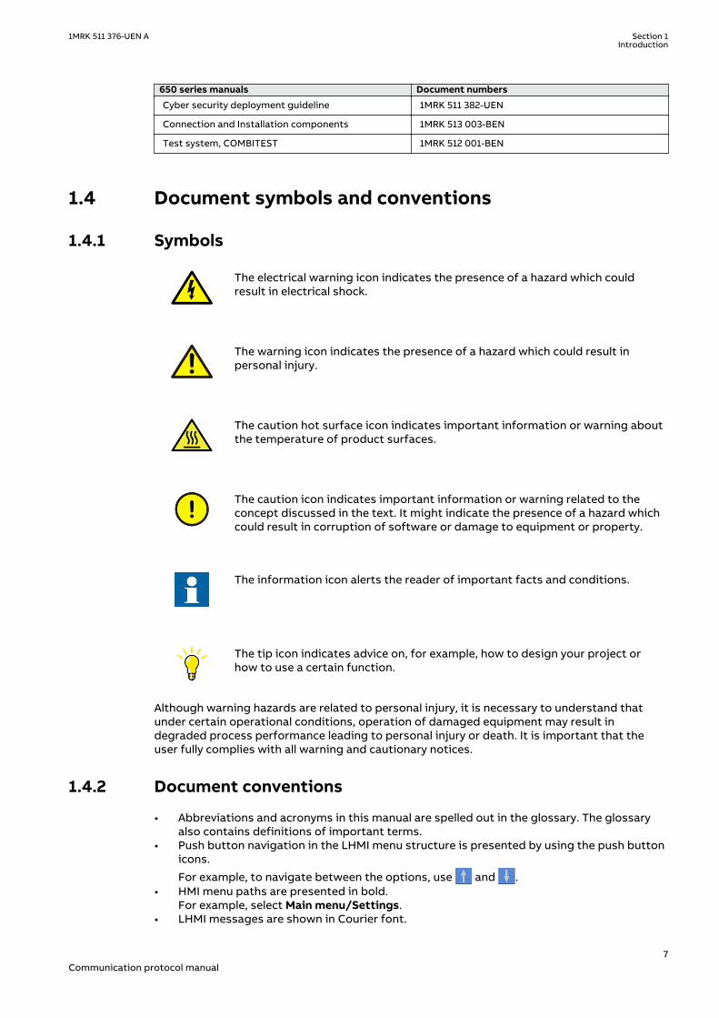
1.4.1 SymbolsGUID-2945B229-DAB0-4F15-8A0E-B9CF0C2C7B15 v12
The electrical warning icon indicates the presence of a hazard which couldresult in electrical shock.
The warning icon indicates the presence of a hazard which could result inpersonal injury.
The caution hot surface icon indicates important information or warning aboutthe temperature of product surfaces.
The caution icon indicates important information or warning related to theconcept discussed in the text. It might indicate the presence of a hazard whichcould result in corruption of software or damage to equipment or property.
The information icon alerts the reader of important facts and conditions.
The tip icon indicates advice on, for example, how to design your project orhow to use a certain function.
Although warning hazards are related to personal injury, it is necessary to understand thatunder certain operational conditions, operation of damaged equipment may result indegraded process performance leading to personal injury or death. It is important that theuser fully complies with all warning and cautionary notices.
1.4.2 Document conventionsGUID-96DFAB1A-98FE-4B26-8E90-F7CEB14B1AB6 v8
• Abbreviations and acronyms in this manual are spelled out in the glossary. The glossaryalso contains definitions of important terms.
• Push button navigation in the LHMI menu structure is presented by using the push buttonicons.
For example, to navigate between the options, use and .• HMI menu paths are presented in bold.
For example, select Main menu/Settings.• LHMI messages are shown in Courier font.
1MRK 511 376-UEN A Section 1Introduction
7Communication protocol manual
For example, to save the changes in non-volatile memory, select Yes and press .• Parameter names are shown in italics.
For example, the function can be enabled and disabled with the Operation setting.• Each function block symbol shows the available input/output signal.
• the character ^ in front of an input/output signal name indicates that the signalname may be customized using the PCM600 software.
• the character * after an input signal name indicates that the signal must beconnected to another function block in the application configuration to achieve avalid application configuration.
• Dimensions are provided both in inches and millimeters. If it is not specifically mentionedthen the dimension is in millimeters.
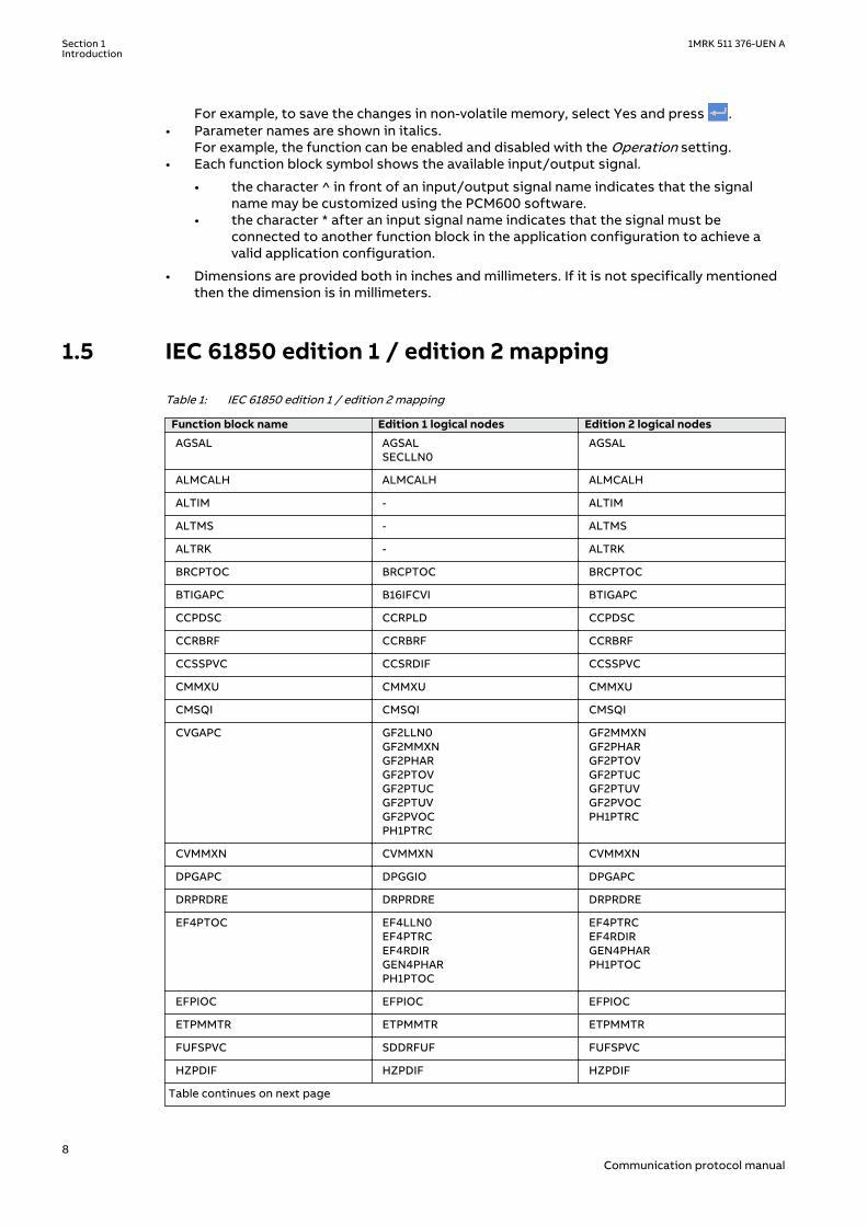
1.5 IEC 61850 edition 1 / edition 2 mappingGUID-C5133366-7260-4C47-A975-7DBAB3A33A96 v3
Table 1: IEC 61850 edition 1 / edition 2 mapping
Function block name Edition 1 logical nodes Edition 2 logical nodes
AGSAL AGSALSECLLN0
AGSAL
ALMCALH ALMCALH ALMCALH
ALTIM - ALTIM
ALTMS - ALTMS
ALTRK - ALTRK
BRCPTOC BRCPTOC BRCPTOC
BTIGAPC B16IFCVI BTIGAPC
CCPDSC CCRPLD CCPDSC
CCRBRF CCRBRF CCRBRF
CCSSPVC CCSRDIF CCSSPVC
CMMXU CMMXU CMMXU
CMSQI CMSQI CMSQI
CVGAPC GF2LLN0GF2MMXNGF2PHARGF2PTOVGF2PTUCGF2PTUVGF2PVOCPH1PTRC
GF2MMXNGF2PHARGF2PTOVGF2PTUCGF2PTUVGF2PVOCPH1PTRC
CVMMXN CVMMXN CVMMXN
DPGAPC DPGGIO DPGAPC
DRPRDRE DRPRDRE DRPRDRE
EF4PTOC EF4LLN0EF4PTRCEF4RDIRGEN4PHARPH1PTOC
EF4PTRCEF4RDIRGEN4PHARPH1PTOC
EFPIOC EFPIOC EFPIOC
ETPMMTR ETPMMTR ETPMMTR
FUFSPVC SDDRFUF FUFSPVC
HZPDIF HZPDIF HZPDIF
Table continues on next page
Section 1 1MRK 511 376-UEN AIntroduction
8Communication protocol manual
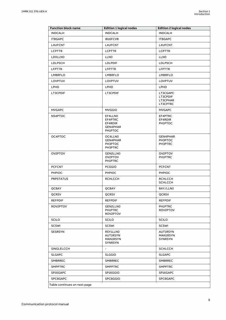
Function block name Edition 1 logical nodes Edition 2 logical nodes
INDCALH INDCALH INDCALH
ITBGAPC IB16FCVB ITBGAPC
L4UFCNT L4UFCNT L4UFCNT
LCPTTR LCPTTR LCPTTR
LD0LLN0 LLN0 LLN0
LDLPSCH LDLPDIF LDLPSCH
LFPTTR LFPTTR LFPTTR
LMBRFLO LMBRFLO LMBRFLO
LOVPTUV LOVPTUV LOVPTUV
LPHD LPHD LPHD
LT3CPDIF LT3CPDIF LT3CGAPCLT3CPDIFLT3CPHARLT3CPTRC
MVGAPC MVGGIO MVGAPC
NS4PTOC EF4LLN0EF4PTRCEF4RDIRGEN4PHARPH1PTOC
EF4PTRCEF4RDIRPH1PTOC
OC4PTOC OC4LLN0GEN4PHARPH3PTOCPH3PTRC
GEN4PHARPH3PTOCPH3PTRC
OV2PTOV GEN2LLN0OV2PTOVPH1PTRC
OV2PTOVPH1PTRC
PCFCNT PCGGIO PCFCNT
PHPIOC PHPIOC PHPIOC
PRPSTATUS RCHLCCH RCHLCCHSCHLCCH
QCBAY QCBAY BAY/LLN0
QCRSV QCRSV QCRSV
REFPDIF REFPDIF REFPDIF
ROV2PTOV GEN2LLN0PH1PTRCROV2PTOV
PH1PTRCROV2PTOV
SCILO SCILO SCILO
SCSWI SCSWI SCSWI
SESRSYN RSY1LLN0AUT1RSYNMAN1RSYNSYNRSYN
AUT1RSYNMAN1RSYNSYNRSYN
SINGLELCCH - SCHLCCH
SLGAPC SLGGIO SLGAPC
SMBRREC SMBRREC SMBRREC
SMPPTRC SMPPTRC SMPPTRC
SP16GAPC SP16GGIO SP16GAPC
SPC8GAPC SPC8GGIO SPC8GAPC
Table continues on next page
1MRK 511 376-UEN A Section 1Introduction
9Communication protocol manual
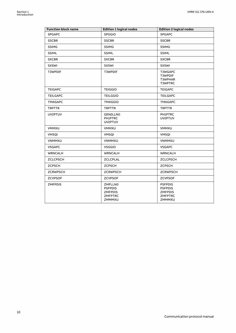
Function block name Edition 1 logical nodes Edition 2 logical nodes
SPGAPC SPGGIO SPGAPC
SSCBR SSCBR SSCBR
SSIMG SSIMG SSIMG
SSIML SSIML SSIML
SXCBR SXCBR SXCBR
SXSWI SXSWI SXSWI
T3WPDIF T3WPDIF T3WGAPCT3WPDIFT3WPHART3WPTRC
TEIGAPC TEIGGIO TEIGAPC
TEILGAPC TEILGGIO TEILGAPC
TMAGAPC TMAGGIO TMAGAPC
TRPTTR TRPTTR TRPTTR
UV2PTUV GEN2LLN0PH1PTRCUV2PTUV
PH1PTRCUV2PTUV
VMMXU VMMXU VMMXU
VMSQI VMSQI VMSQI
VNMMXU VNMMXU VNMMXU
VSGAPC VSGGIO VSGAPC
WRNCALH WRNCALH WRNCALH
ZCLCPSCH ZCLCPLAL ZCLCPSCH
ZCPSCH ZCPSCH ZCPSCH
ZCRWPSCH ZCRWPSCH ZCRWPSCH
ZCVPSOF ZCVPSOF ZCVPSOF
ZMFPDIS ZMFLLN0PSFPDISZMFPDISZMFPTRCZMMMXU
PSFPDISPSFPDISZMFPDISZMFPTRCZMMMXU
Section 1 1MRK 511 376-UEN AIntroduction
10Communication protocol manual
Section 2 Introduction to IEC 61850
2.1 OverviewGUID-66925336-B6C3-4B22-95F4-A3321B63FABB v7
The general scope of the IEC 61850 protocol standard is designed to support thecommunication of all functions being performed in the substation. Its’ main goal isinteroperability; this is the ability for IEDs from one or different manufacturers to exchangeinformation and use the information for their own functions. Moreover, the standard allows afree allocation of these functions and accepts any system philosophy, from a distributedarchitecture (for example, decentralised substation automation) to a centralised configuration(for example, RTU based).
The standard separates the functionality represented by the data model and the relatedcommunication services from the communication implementation (stack).
The data model of the standard is an object-oriented one, grouping the data into the smallestpossible sets referring to the smallest possible functions to be implemented independently.These smallest possible data groups or functions are named logical nodes. The logical nodesand all data and attributes contained are named according to a standardised semantic, whichis mandatory.
This manual describes how the IEC 61850 standard is applied in the IEDs. References and briefdescriptions of the standard are also included. It is assumed that the reader has basicknowledge of the IEC 61850 standard.
The following parts of the IEC 61850 standard are of importance as they relate to this manual:
• Station Configuration description Language (SCL) is described in IEC 61850-6. The SCL isan XML based definition of how to describe the parts of a substation. This part of thestandard also includes the roles of different tools as well as the engineering concepts.
• Communication profile (IEC 61850 stack) is described in IEC 61850-8-1. This part of thestandard includes a number of possible communication profiles, and how the servicesdefined in IEC 61850-7-2 are mapped to the communication profile.
• Communication services are described in IEC 61850-7-2. This part deals mainly with thecommunication facilities from client and server point of view. It includes the differentpossibilities of communication functionality.
• Logical node data model. This is described in IEC 61850-7-3 and IEC 61850-7-4.• Conformance tests and the basis for conformance documents are handled in IEC
61850-10.
Detailed information regarding the IEC 61850 implementation of the IED is described insidethe conformance documents.
• MICS, Modeling Information Conformance Statement, contains the declaration of theused logical node types.
• PICS, Protocol Information Conformance Statement, contains the details and what issupported regarding protocol facilities.
• PIXIT, Protocol Extra Information, contains additional information on how the IEC 61850 isimplemented and used.
• TICS, Tissue Information Conformance Statement, contains the supported Tissues, whichare handled in the Tissues process as defined by UCA, Utility Communication Architectureforum. The Tissues handling is found in http://www.tissue.iec61850.com.
1MRK 511 376-UEN A Section 2Introduction to IEC 61850
11Communication protocol manual
The conformance documents are unique for each product release and refer to each other. Theidentities included in the related documents refer to a specific version of the IED series.
The communication profile in IEC 61850 uses the MMS standard, which uses Ethernet andTCP/IP to handle the information transport within the substation.
The data modelling uses the concept of logical nodes to identify the published information forcommunication. The standard defines a set of logical nodes, each representing acommunication view of a process function with a number of data objects. For example, atransformer differential - or line differential protection, because the standard defines only adifferential protection. Therefore, it is possible to adapt the logical node, which is defined inthe standard, as a logical node class. The standard defines methods to describe the actuallyused logical node as a logical node type which is then based upon the logical node class. Thisallows all partners to interpret the logical node type information because the description iscompletely given in the standard. The type description of all logical nodes is part of the DataType Template (DTT) section in the SCL description file of a station or the IED.
Besides the information about the configuration of the communication facilities, this manualcontains the full description of all logical nodes available in the IEDs. The information aboutthe logical nodes and their data objects may be used to identify which signals are available forthe functions as described in the technical manual. The link to the technical manual is done inthe logical node tables by listing the signal name as given in the function block, or as seen inPCM600 or the LHMI.
2.1.1 Related documentation to IEC 61850GUID-906D4C7F-29FD-4922-8A8B-8A3A3E2B811E v5
Use the latest revision of the documents listed, unless stated otherwise.
Document ID Title
IEC 61850-SEREd1.0 (2013-12-12) - (English)
Communication networks and systems insubstations -ALL PARTS
IEC 61850-3Ed2.0 (2013-12-12) - (English - French)
Communication networks and systems for powerutility automation -Part 3:General requirements
IEC 61850-4Ed2.0 (2011-04-11) - (English - French)
Communication networks and systems for powerutility automation -Part 4:System and project management
IEC 61850-5Ed2.0 (2013-01-30) - (English - French)
Communication networks and systems for powerutility automation -Part 5:Communication requirements for functions anddevices models
IEC 61850-6Ed2.0 (2009-12-17) - (English)
Communication networks and systems for powerutility automation -Part 6:Configuration description language forcommunication in electrical substations related toIEDs
IEC 61850-7-1Ed2.0 (2011-07-15) - (English - French)
Communication networks and systems for powerutility automation -Part 7-1:Basic communication structure -Principles and models
Table continues on next page
Section 2 1MRK 511 376-UEN AIntroduction to IEC 61850
12Communication protocol manual
IEC 61850-7-2Ed2.0 (2010-08-24) - (English)
Communication networks and systems for powerutility automation -Part 7-2:Basic information and communication structure -Abstract communication service interface (ACSI)
IEC 61850-7-3Ed2.0 (2010-12-16) - (English - French)
Communication networks and systems for powerutility automation -Part 7-3:Basic communication structure -Common data classes
IEC 61850-7-4Ed2.0 (2010-03-31) - (English)
Communication networks and systems for powerutility automation -Part 7-4:Basic communication structure -Compatible logical node classes and data objectclasses
IEC 61850-7-410Ed2.0 (2012-10-30) - (English - French)
Communication networks and systems for powerutility automation -Part 7-410:Basic communication structure -Hydroelectric power plants -Communication for monitoring and control
IEC 61850-7-420Ed1.0 (2009-03-10) - (English)
Communication networks and systems for powerutility automation -Part 7-420:Basic communication structure -Distributed energy resources logical nodes
IEC 61850-8-1Ed2.0 (2011-06-17) - (English - French)
Communication networks and systems for powerutility automation -Part 8-1:Specific Communication Service Mapping (SCSM) -Mappings to MMS (ISO 9506-1 and ISO 9506-2) and toISO/IEC 8802-3
IEC 61850-9-2Ed2.0 (2011-09-22) - (English - French)
Communication networks and systems for powerutility automation -Part 9-2:Specific Communication Service Mapping (SCSM) -Sampled values over ISO/IEC 8802-3
IEC 61850-10Ed2.0 (2012-12-14) - (English - French)
Communication networks and systems for powerutility automation -Part 10:Conformance testing
IEC 61850 MICS1MRG021098
IED series version 2.1 Ed2 - MICS:Modelling implementation conformance statement
IEC 61850 PICS1MRG021052
IED series version 2.1 Ed2 - PICS:Protocol implementation conformance statement
IEC 61850 PIXIT1MRG021053
IED series version 2.1 Ed2 - PIXIT:Protocol implementation extra information
IEC 61850 TICS1MRG021051
IED series version 2.1 Ed2 - TICS:Tissue implementation conformance statement
1MRK 511 376-UEN A Section 2Introduction to IEC 61850
13Communication protocol manual

14

Section 3 Substation Configurationdescription Language (SCL)
SEMOD129808-4 v8
Four different types of SCL files - SCD, CID, IID, and ICD, can be exported from PCM 600.
The SCL language is based on XML. However, detailed knowledge of the XML contents is notneeded.
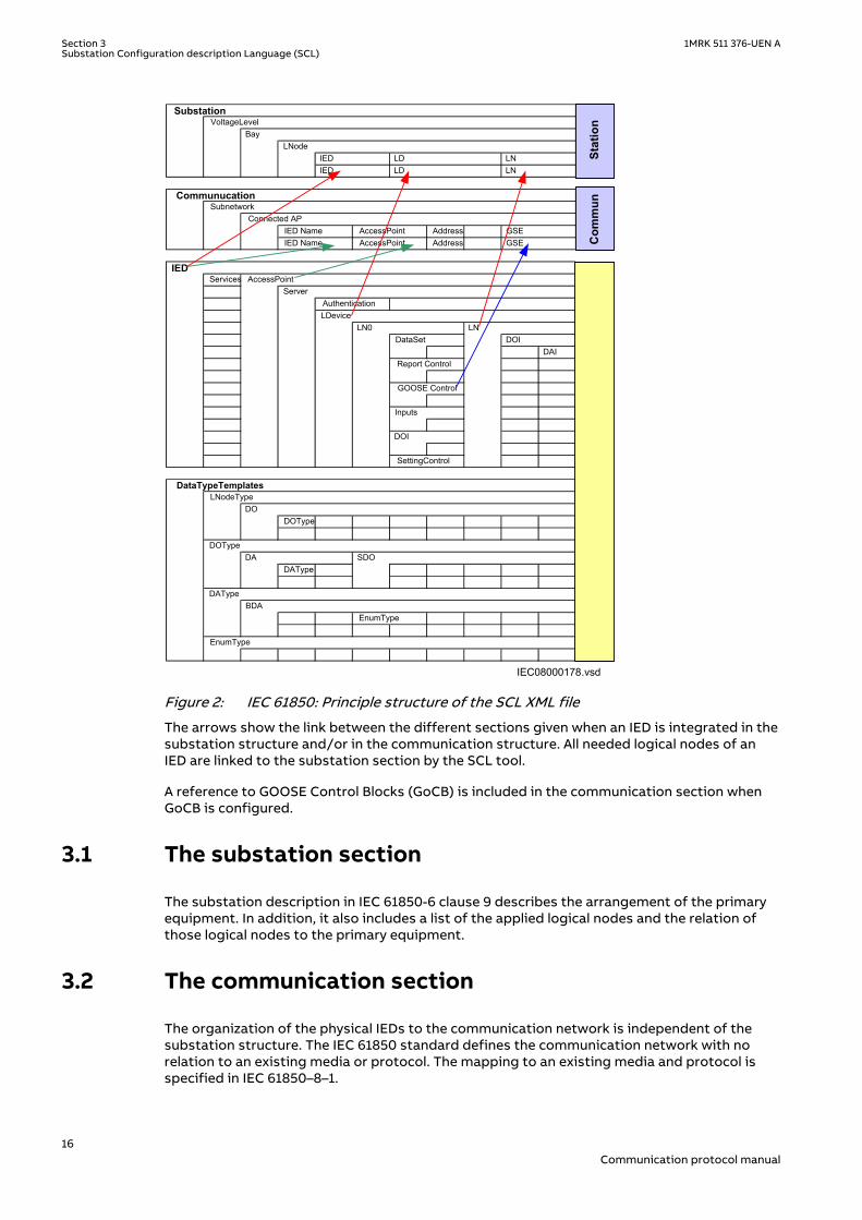
The SCL XML file (ICD/SCD/CID/IID) contains five sections, which are specified in IEC 61850–6clause 9.
• Header• Substation section describes the functional structure and its relation to primary devices.• Communication section describes the connection between the IED access points to the
respective subnetwork. and includes also the properties (addresses) of the access points.• IED section contains a description of the supported communication services, the access
point(s) and the IEDs logical devices, logical nodes and their attributes.• Data type template section contains a declaration of all types used in the SCL file, logical
nodes type, DO types, attributes and enums.
The system structure is defined by the organization of the plant structure in PCM600. Thesignal engineering and the signal routing are IET600 tasks, signal engineering regarding DS,rcb,gcb, GOOSE subscribers can be done also in PCM600. The IED needs to be configured withPCM600 before the system is configured with IET600.
The SCL engineering must be done in an SCL engineering tool. The data sets and the controlblocks are logically defined as part of the logical nodes (see IEC 61850–7–2 clause 9). The IEDalso needs a correctly configured communication section for GOOSE engineering, which canbe done in IET600 or PCM600.
The data type templates section provides the correct content description of each logical nodetype to all tools and users (clients) of the information. Each IED and vendor may have their ownlogical node type definitions included in the data type template section together with all otherlogical node types based on the standard.
1MRK 511 376-UEN A Section 3Substation Configuration description Language (SCL)
15Communication protocol manual
IEC08000178.vsd
IED Name AccessPoint Address GSEIED Name AccessPoint Address GSE
Services
AuthenticationLDevice
DAI
DOType
DAType
EnumType
SubstationVoltageLevel
BayLNode
IED LD LNIED LD LN
CommunucationSubnetwork
Connected AP
IEDAccessPoint
Server
GOOSE Control
LN0 LNDataSet DOI
DataTypeTemplates
Report Control
Inputs
DOI
SettingControl
LNodeType
DOType
DAType
EnumType
DO
DA
IED
SDO
BDAStation
Com
mun
IEC08000178 V1 EN-US
Figure 2: IEC 61850: Principle structure of the SCL XML file
The arrows show the link between the different sections given when an IED is integrated in thesubstation structure and/or in the communication structure. All needed logical nodes of anIED are linked to the substation section by the SCL tool.
A reference to GOOSE Control Blocks (GoCB) is included in the communication section whenGoCB is configured.
3.1 The substation sectionSEMOD129763-4 v4
The substation description in IEC 61850-6 clause 9 describes the arrangement of the primaryequipment. In addition, it also includes a list of the applied logical nodes and the relation ofthose logical nodes to the primary equipment.
3.2 The communication sectionSEMOD129771-4 v3
The organization of the physical IEDs to the communication network is independent of thesubstation structure. The IEC 61850 standard defines the communication network with norelation to an existing media or protocol. The mapping to an existing media and protocol isspecified in IEC 61850–8–1.
Section 3 1MRK 511 376-UEN ASubstation Configuration description Language (SCL)
16Communication protocol manual
The IEC 61850 standard describes in part 7–2 the ACSI in a media and protocol independentform. Part 8–1 specifies the mapping of this ACSI to the existing MMS.
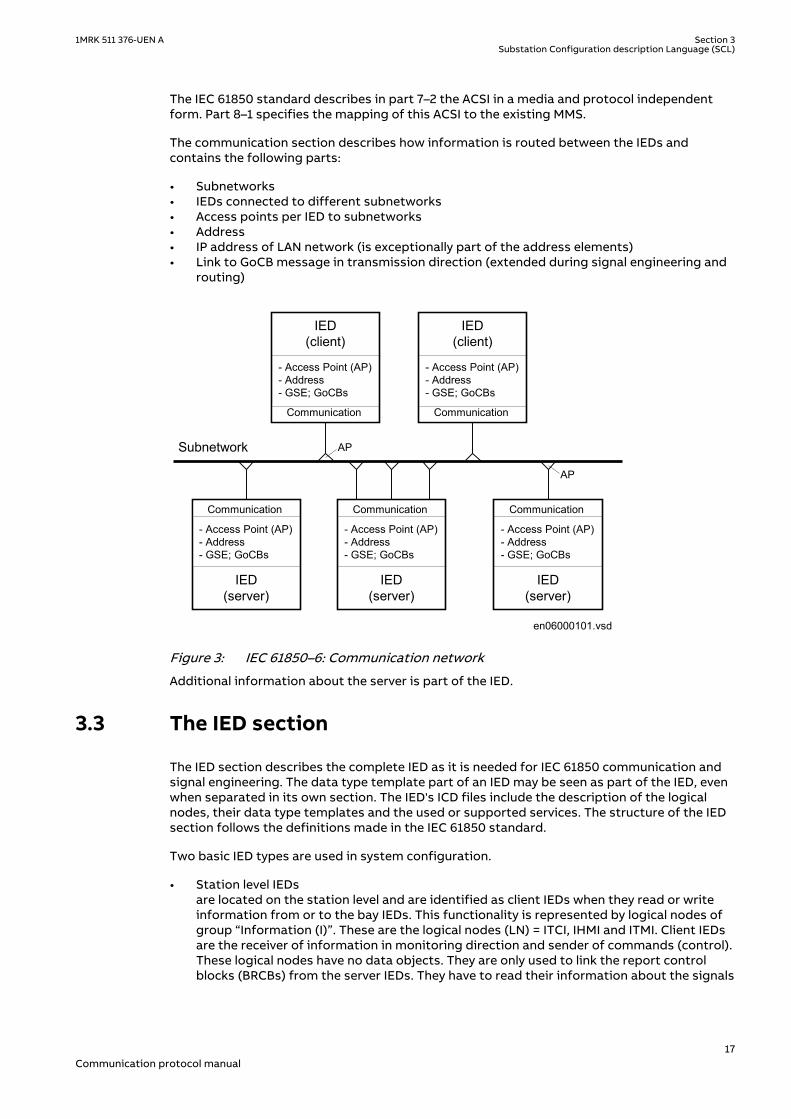
The communication section describes how information is routed between the IEDs andcontains the following parts:
• Subnetworks• IEDs connected to different subnetworks• Access points per IED to subnetworks• Address• IP address of LAN network (is exceptionally part of the address elements)• Link to GoCB message in transmission direction (extended during signal engineering and
routing)
en06000101.vsd
IED(server)
- Access Point (AP)- Address- GSE; GoCBs
Communication
AP
IED(server)
- Access Point (AP)- Address- GSE; GoCBs
Communication
IED(server)
- Access Point (AP)- Address- GSE; GoCBs
Communication
AP
IED(client)
- Access Point (AP)- Address- GSE; GoCBs
Communication
IED(client)
- Access Point (AP)- Address- GSE; GoCBs
Communication
Subnetwork
IEC06000101 V1 EN-US
Figure 3: IEC 61850–6: Communication network
Additional information about the server is part of the IED.
3.3 The IED sectionSEMOD129775-4 v6
The IED section describes the complete IED as it is needed for IEC 61850 communication andsignal engineering. The data type template part of an IED may be seen as part of the IED, evenwhen separated in its own section. The IED's ICD files include the description of the logicalnodes, their data type templates and the used or supported services. The structure of the IEDsection follows the definitions made in the IEC 61850 standard.
Two basic IED types are used in system configuration.
• Station level IEDsare located on the station level and are identified as client IEDs when they read or writeinformation from or to the bay IEDs. This functionality is represented by logical nodes ofgroup “Information (I)”. These are the logical nodes (LN) = ITCI, IHMI and ITMI. Client IEDsare the receiver of information in monitoring direction and sender of commands (control).These logical nodes have no data objects. They are only used to link the report controlblocks (BRCBs) from the server IEDs. They have to read their information about the signals
1MRK 511 376-UEN A Section 3Substation Configuration description Language (SCL)
17Communication protocol manual
and the signal configuration from the bay IEDs. This is possible by checking all controlblocks for a link to it as a client.
• Bay level IEDsare located on the bay level and are identified as server IEDs when they read or writeinformation vertically. When GOOSE messages are received, the bay level IED also has theclient role.
en06000104.vsd
AP
Subnetwork
Control
IED
CVMMXU1
SB1.LD0
Server
LPHD
SXCBR1
SCSWI1
SXSWI1
SCSWI2
SXSWI2
SCSWI3
SXSWI3
SCSWI4
SXSWI4
SCSWI5
LLN0
Mod
CBOpCap
Origin
Data
DataAttribute
Beh
Health
NamePlt
ctlValPos
Loc
OpCnt
BlkOpn
BlkCls
stVal
q
t
LogicalNode
ctlModel
IEC06000104 V2 EN-US
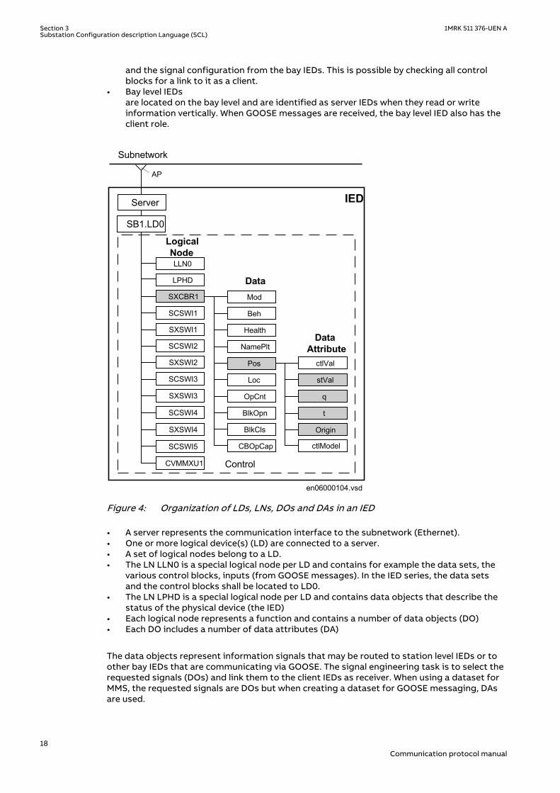
Figure 4: Organization of LDs, LNs, DOs and DAs in an IED
• A server represents the communication interface to the subnetwork (Ethernet).• One or more logical device(s) (LD) are connected to a server.• A set of logical nodes belong to a LD.• The LN LLN0 is a special logical node per LD and contains for example the data sets, the
various control blocks, inputs (from GOOSE messages). In the IED series, the data setsand the control blocks shall be located to LD0.
• The LN LPHD is a special logical node per LD and contains data objects that describe thestatus of the physical device (the IED)
• Each logical node represents a function and contains a number of data objects (DO)• Each DO includes a number of data attributes (DA)
The data objects represent information signals that may be routed to station level IEDs or toother bay IEDs that are communicating via GOOSE. The signal engineering task is to select therequested signals (DOs) and link them to the client IEDs as receiver. When using a dataset forMMS, the requested signals are DOs but when creating a dataset for GOOSE messaging, DAsare used.
Section 3 1MRK 511 376-UEN ASubstation Configuration description Language (SCL)
18Communication protocol manual

The number of data objects and data attributes per DO is defined by the used LN type in theIED. The content of logical node types and DO types are defined in the DTT. This also meansthat the definitions in the DTT section have to be unique within an SCD file.
3.4 Tool conceptGUID-93477EC1-9BB4-4CCE-8603-0D910BDD661B v6
The IEC 61850-6 defines a number of roles for tools. In the Relion® series, PCM600 is defined asthe IED tool, and IET600 is defined as the system engineering tool.
The sections in SCL contain properties that are to be configured by these tools. There is norelation between one section and one specific tool. The task of the IED tool is to configure allproperties for the IED, while the system tool has the task to define the place of the IED in thesystem and its communication dependencies. For example, the plant structure in PCM600results in the subsystem section in SCL regarding the subsystem structure down to the IEDlevel. The PCM600 also configures the IED section as a result of the IED configuration. InPCM600, the configuration properties for SCL are handled automatically as a result of theconfiguration, except for the receiving of GOOSE information that has a dependency with thesystem tool.
IEC 61850 engineering with PCM600, PCM600 IEC 61850 Configuration tool and IET600
PCM600:
• When an IED is instantiated, its place in the plant structure creates the correspondingstructure in the substation section in SCL. The communication facilities is also created inthe communication section.
• The functionality of the IED is configured by using ACT in PCM600. For each function, thecorresponding logical device and logical node(s) is created in the IED section togetherwith its type definition in data type template section
• The above forms the IED capabilities from a communication perspective and will then beincluded in the file exported from PCM600 as SCD, ICD, IID and CID file
PCM600: IEC 61850 Configuration tool
• Included in PCM600 is the new IEC 61850 Configuration tool which allows the user todefine data sets and control blocks for both Client Server and GOOSE communication.
• The IEC 61850 Configuration tool gives the user the possibility to make the IEC 61850engineering without export / import step.
It does NOT however allow the User to define the substation part.
IET600:
• Open a SCD file or import/merge a SCD, ICD or CID file for the particular IED(s).• For each IED, the user defines the datasets, the control blocks for reporting (this means
unbufffered/buffered reporting and GOOSE) and the properties for each report controlblock.
1MRK 511 376-UEN A Section 3Substation Configuration description Language (SCL)
19Communication protocol manual
Data sets (DS) are generated automatically in PCM600. Report controlblocks (RCBs) are not generated automatically in PCM600.
• If client definitions (like client. ICD) are required in the system configuration, they aremerged into IET600 and connected to the unbuffered/buffered report control blocks.
• Logical nodes, which are not related to the conducting equipment, must be included in thebay level in the substation section.
• The resulting SCD file is exported from IET600.
PCM600:
Define the inputs for the client in IET600 and cross-reference the signals in SMT. Import theSCD file to PCM600 to receive GOOSE data. For each IED that shall receive GOOSE information,the received data is connected to the applications using SMT in PCM600.To be able to importscd-file to PCM600 61850 engineering in PCM must be set to disabled.
If input signals are not defined for clients in IET600, they will not be visible inSMT. Inputs (GOOSE clients) can also be defined in PCM600.
3.5 Engineering concept in IEC 61850-6GUID-FFE87459-FBC1-4D85-A6B3-7BD6F576ECE4 v3
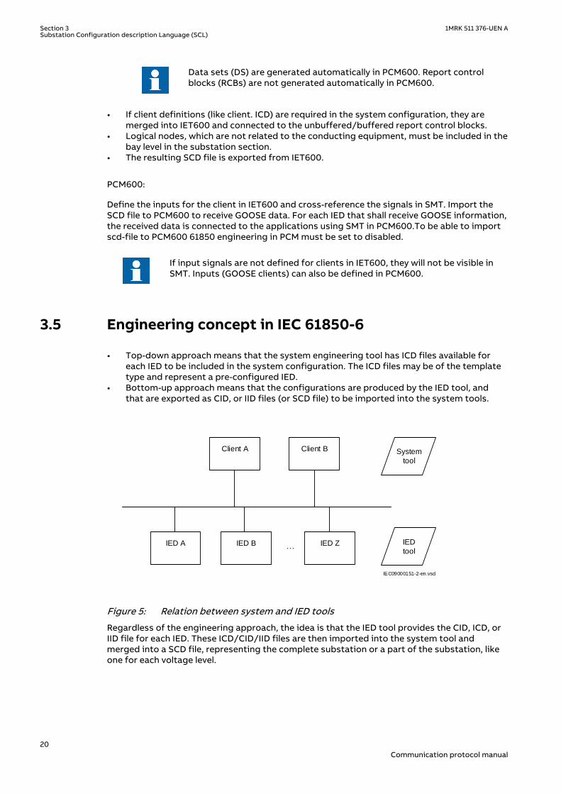
• Top-down approach means that the system engineering tool has ICD files available foreach IED to be included in the system configuration. The ICD files may be of the templatetype and represent a pre-configured IED.
• Bottom-up approach means that the configurations are produced by the IED tool, andthat are exported as CID, or IID files (or SCD file) to be imported into the system tools.
…IED A IED B IED Z
Client A
IED
tool
System
tool
IEC09000151-2-en.vsd
Client B
IEC09000151 V2 EN-US
Figure 5: Relation between system and IED tools
Regardless of the engineering approach, the idea is that the IED tool provides the CID, ICD, orIID file for each IED. These ICD/CID/IID files are then imported into the system tool andmerged into a SCD file, representing the complete substation or a part of the substation, likeone for each voltage level.
Section 3 1MRK 511 376-UEN ASubstation Configuration description Language (SCL)
20Communication protocol manual
Section 4 Communication profile
GUID-25495333-A2B7-44A7-908D-68EC06694AD5 v6
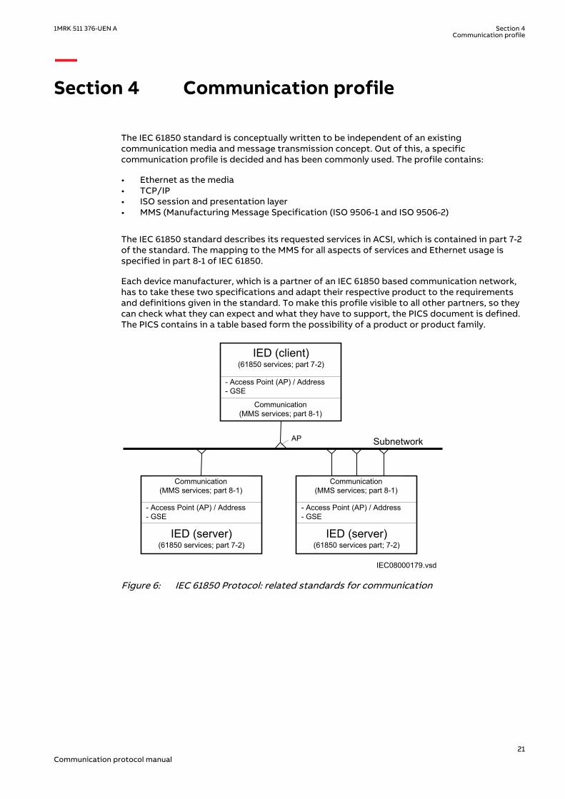
The IEC 61850 standard is conceptually written to be independent of an existingcommunication media and message transmission concept. Out of this, a specificcommunication profile is decided and has been commonly used. The profile contains:
• Ethernet as the media• TCP/IP• ISO session and presentation layer• MMS (Manufacturing Message Specification (ISO 9506-1 and ISO 9506-2)
The IEC 61850 standard describes its requested services in ACSI, which is contained in part 7-2of the standard. The mapping to the MMS for all aspects of services and Ethernet usage isspecified in part 8-1 of IEC 61850.
Each device manufacturer, which is a partner of an IEC 61850 based communication network,has to take these two specifications and adapt their respective product to the requirementsand definitions given in the standard. To make this profile visible to all other partners, so theycan check what they can expect and what they have to support, the PICS document is defined.The PICS contains in a table based form the possibility of a product or product family.
IED (server)(61850 services; part 7-2)
Communication(MMS services; part 8-1)
- Access Point (AP) / Address- GSE
IEC08000179.vsd
AP
IED (client)(61850 services; part 7-2)
Subnetwork
IED (server)(61850 services part; 7-2)
Communication(MMS services; part 8-1)
Communication(MMS services; part 8-1)
- Access Point (AP) / Address- GSE
- Access Point (AP) / Address- GSE
IEC08000179 V1 EN-US
Figure 6: IEC 61850 Protocol: related standards for communication
1MRK 511 376-UEN A Section 4Communication profile
21Communication protocol manual
SV GOOSE TimeSync(SNTP) MMS Protocol Suite GSSE
TCP/IPT-Profile
ISO COT-Profile
ISO/IEC 8802-2 LLC
GSSET-ProfileUDP/IP
ISO/IEC 8802-3 Ethertype
SampledValues(Multicast)
GenericObjectOrientedSubstationEvent
TimeSync
CoreACSIServices
GenericSubstationStatusEvent
ISO/IEC 8802-3
IEC09000153-1-en.vsdIEC09000153 V1 EN-US
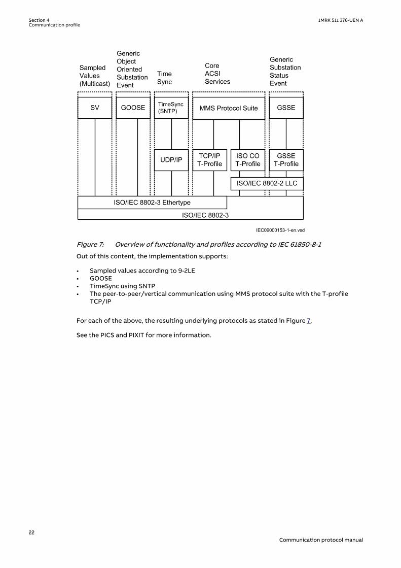
Figure 7: Overview of functionality and profiles according to IEC 61850-8-1
Out of this content, the implementation supports:
• Sampled values according to 9-2LE• GOOSE• TimeSync using SNTP• The peer-to-peer/vertical communication using MMS protocol suite with the T-profile
TCP/IP
For each of the above, the resulting underlying protocols as stated in Figure 7.
See the PICS and PIXIT for more information.
Section 4 1MRK 511 376-UEN ACommunication profile
22Communication protocol manual
Section 5 Supported services
GUID-E08C91D7-A59B-478B-B39A-26E786591E2A v7
IEC 61850-7-2 describes the services in the standard. IEC 61850-8-1 describes how the servicesare applied in the communication. The conformance documents contain the description of thesupported services in the IED.
Services that are not mentioned in this chapter or in the conformance document are notsupported by the IED.
GOOSE simulation is supported according to IEC 61850 7-2.
If LD0.PHD.ST.Sim.stVal is set to true, then incoming GOOSE with test-bit in GOOSE header setis treated as real GOOSE and real GOOSE is discarded starting on first received GOOSE withtest-bit set until LD0.LPHD.ST.Sim.stVal is rested to false. After that the real GOOSE is activeagain and GOOSE with test-bit set is discarded.
Data set
Define data sets by the SCD description.
Create data sets under LD0/LLN0.
For more information on data sets, see the PIXIT-related documents.
Substitution
Substitution is supported for the respective DATA, according to IEC 61850-7-4, that have thesubstitution attributes defined.
Setting group control block
There is only one setting group control block, which is located in LD0/LLN0 (Logical Device0/Logical Node 0).
Change or edit of some setting values as well as reading of setting values is supported in IEC61850. Note that change/edit of setting over IEC 61850 is only supported when the IED isconfigured in Edition 2 mode.
In the IED a parameter regarding IEC 61850 settings has to be enabled to allow writing/modifying settings from a IEC 61850 client. The status of output REMSETEN in the functionblock ACTVGRP in the IED shows whether it is possible or not to change settings over IEC61850.
The Setting range is expressed in the minVal and maxVal data attributes (DAs) in each settingdata object (DO). When writing settings a check will be done to compare the new value withthe minVal and maxVal attributes, when applicable (this depends on the data type and if theminVal and maxVal are mapped). So if the minVal and maxVal is not mapped, all values in therange of the data type will be accepted. If the written value is outside the range, Object-Value-Invalid will be returned to the client.
Note that the actual number of used setting groups is defined by theparameter MaxNoSetGRP in the function SETGRPS, which is configured in PSTin PCM600. But six setting groups is the maximum and it cannot be exceeded.
1MRK 511 376-UEN A Section 5Supported services
23Communication protocol manual
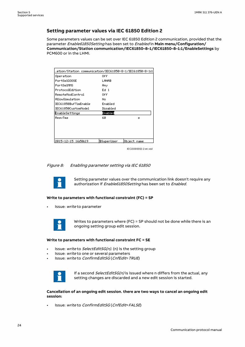
Setting parameter values via IEC 61850 Edition 2
Some parameters values can be set over IEC 61850 Edition 2 communication, provided that theparameter Enable61850Setting has been set to Enabled in Main menu/Configuration/Communication/Station communication/IEC61850–8–1/IEC61850–8–1:1/EnableSettings byPCM600 or in the LHMI.
IEC15000002-2-en.vsd
IEC15000002 V2 EN-US
Figure 8: Enabling parameter setting via IEC 61850
Setting parameter values over the communication link doesn't require anyauthorization if Enable61850Setting has been set to Enabled.
Write to parameters with functional constraint (FC) = SP
• Issue: write to parameter
Writes to parameters where (FC) = SP should not be done while there is anongoing setting group edit session.
Write to parameters with functional constraint FC = SE
• Issue: write to SelectEditSG(n). (n) is the setting group• Issue: write to one or several parameters• Issue: write to ConfirmEditSG (CnfEdit=TRUE)
If a second SelectEditSG(n) is issued where n differs from the actual, anysetting changes are discarded and a new edit session is started.
Cancellation of an ongoing edit session. there are two ways to cancel an ongoing editsession:
• Issue: write to ConfirmEditSG (CnfEdit=FALSE)
Section 5 1MRK 511 376-UEN ASupported services
24Communication protocol manual
or
• Issue: write to SelectEditSG(0)
Reading values where FC = SP
• Issue: read from parameter
Report control block
For properties about report control blocks, see PIXIT.
UnBuffered reporting as well as Buffered reporting is supported.
Generic object oriented substation event (GOOSE)
The structured GOOSE is supported. This means that the data sets can be defined with FCDAas well as explicit attributes.
The supported data types to be published and received over GOOSE are binary values, doublepoint values, integer values and measured values, together with their quality. One signal isavailable inside the application to validate the reception of a GOOSE message. Invalid meansthat the correct GOOSE message is not received prior 2*TAL(Time Allowed to Live).
GOOSE with TAL= 0 ms is treated as GOOSE with TAL = 100 ms and accepted.
Note that the data sets that are used or referred to by GOOSE control blockscan only include a data attribute once. In other words, there may not be thesame data attribute in more than one data set.
When publishing a measured value, the user must take care of which measured value dataattributes are added to a data set. If the measured value is event-handled (like in the case ofMMXU functions), then one can add that value directly to the data set. If the value is not event-handled, (like in the case of Synchrocheck function), it is recommended to connect the valuedesired to be published to a MVGAPC function block (in ACT) and then use the measured valuegiven by the MVGAPC.
Example of functions that have event-handled measured values (can be added directly to thedata set).
• CVMMXN - Measurements• CMMXU - Phase current measurement• VMMXU - Phase-phase voltage measurement• CMSQI - Current sequence component measurement• VMSQI - Voltage sequence measurement• VNMMXU - Phase-neutral voltage measurement• MVGAPC - IEC 61850 generic communication I/ O functions
Generic function blocks are provided to make available to the 61850 bus signals that are notdefined inside any of the available function blocks. Example of such functions include:
1MRK 511 376-UEN A Section 5Supported services
25Communication protocol manual

• SPGAPC - IEC 61850 generic communication I/ O functions• DPGAPC - IEC 61850 generic communication I/ O functions• MVGAPC - IEC 61850 generic communication I/ O functions
Control
Of the different control sequences, the ‘direct-with-normal-security’ and ‘SBO-with-enhanced’security are supported (defined by the ctlModel parameter, IEC 61850-7-2).
Check bits; interlock check and synchrocheck check, are only valid for LN types based uponCSWI class.
Verification of Originator Category is supported, see also PIXIT.
GOOSE simulation
Receiving GOOSE simulation is supported according to IEC 61850-7-2.
You can enable the GOOSE-simulation feature in PST or HMI by setting "AllowSimulation" to"Yes" in Main menu/Configuration/Communication/Station communication/IEC61850–8–1/IEC61850–8–1:1. By enabling ...LD0.LPHD1.Sim.stVal, IEC 61850 is set to "true" and GOOSEsimulation activates. From then on, receiving GOOSE with simulation-bit (set in the GOOSEheader) is treated as real GOOSE and the original real GOOSE is ignored.
If you switch the simulated GOOSE off, the GOOSE receiver does not automatically switch backto the real original GOOSE. Internal GOOSE data is set to invalid, because the simulatedGOOSE is missing. Only if the GOOSE-simulation feature is switched off in PST or HMI bysetting "AllowGOOSESimulation" to "No" (...LD0.LPHD1.Sim.stVal, IEC 61850 is set to "false"),the real GOOSE becomes active again and simulated GOOSE is ignored.
If the PST setting “AllowGOOSESimulation” is set to “No” (default), alloperations to LPHD.Sim data object will be rejected.
Service tracking (available for IEC 61850 Ed2)
The LN ALTRK1 allows to track service parameters. The service parameters will stay visibleafter the execution of service. For this purpose, common data classes are specified whichcontain the parameters of the services according to IEC 61850-7-2 Ed2.
These data objects for service tracking are supported:
• Tracking of services:
• SpcTrk: Control service tracking for controllable single point• DcpTrk: Control service tracking for controllable double point• IncTrk: Control service tracking for controllable integer• EncTrk1: Control service tracking for enumerated controllable• ApcFTrk: Control service tracking for controllable analogue set point with float
command• ApcIntTrk: Control service tracking for controllable analogue set point with integer
command• BscTrk: Control service tracking for binary controlled step position information• IscTrk: Control service tracking for integer controlled step position information• BacTrk: Control service tracking for binary controlled analogue process value
• Tracking of generic services:
• GenTrk: Common service tracking for all services for which no specific tracking dataexists.For supported generic services, see PIXIT.
• Tracking of control block services:
Section 5 1MRK 511 376-UEN ASupported services
26Communication protocol manual

• UrcbTrk: Access service tracking for unbuffered report control block• BrcbTrk: Access service tracking for buffered report control block• LocbTrk: Access service tracking for log control block• GocbTrk: Access service tracking for goose control block• SgcbTrk Access service tracking for setting group control block
1MRK 511 376-UEN A Section 5Supported services
27Communication protocol manual

28
Section 6 Data sets and control blocks
6.1 Data setsSEMOD129786-5 v7
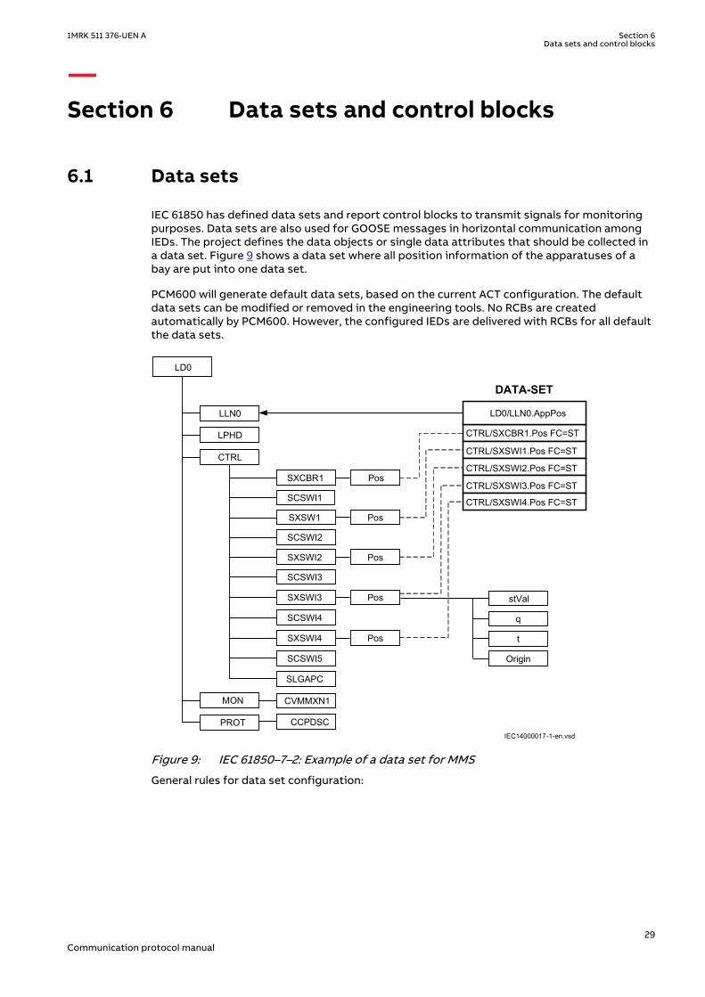
IEC 61850 has defined data sets and report control blocks to transmit signals for monitoringpurposes. Data sets are also used for GOOSE messages in horizontal communication amongIEDs. The project defines the data objects or single data attributes that should be collected ina data set. Figure 9 shows a data set where all position information of the apparatuses of abay are put into one data set.
PCM600 will generate default data sets, based on the current ACT configuration. The defaultdata sets can be modified or removed in the engineering tools. No RCBs are createdautomatically by PCM600. However, the configured IEDs are delivered with RCBs for all defaultthe data sets.
IEC14000017-1-en.vsd
CTRL/SXCBR1.Pos FC=ST
CTRL/SXSWI1.Pos FC=ST
CTRL/SXSWI2.Pos FC=ST
CTRL/SXSWI3.Pos FC=ST
CTRL/SXSWI4.Pos FC=ST
LD0/LLN0.AppPos
DATA-SET
LD0
LPHD
SXCBR1
SCSWI1
SXSW1
SCSWI2
SXSWI2
SCSWI3
SXSWI3
SCSWI4
SXSWI4
SCSWI5
LLN0
Origin
stVal
q
t
CTRL
MON
PROT
SLGAPC
CVMMXN1
CCPDSC
Pos
Pos
Pos
Pos
Pos
IEC14000017 V1 EN-US
Figure 9: IEC 61850–7–2: Example of a data set for MMS
General rules for data set configuration:
1MRK 511 376-UEN A Section 6Data sets and control blocks
29Communication protocol manual
• All data objects or their data attributes can be selected for a data set.• Only those data attributes of a data object can/will be selected which have the same
function constraint (FC).• Data objects with different FC can be selected for a data set. For example, DOs with FC =
ST and DOs with FC=MX can be member in one data set.• A single data attribute can be selected when it is specified with a trigger option. For
example, the data attribute stVal of the data object Pos can be selected as a member of adata set, because it is specified with the trigger option data change detected (dchg).
The description of the data sets with name and the list of data object members (FCDAs isincluded in the SCL file in the IED section in the Logical device subsection. As specified in IEC61850–7–2 clause 9, the data sets are part of a logical node. They are most likely included in theLLN0.
6.2 Report control block (URCB/BRCB)SEMOD129786-17 v5
To be able to transmit the signals configured in a DataSet, a report control block must beconfigured to handle and specify how the events are transmitted to the clients. There are twotypes of report control blocks; unbuffered and buffered. The buffered report control blockstores the events during a communication interrupt, while the unbuffered is sent upon datachange and not stored during interruption.
The content of a BRCB is listed in IEC 61850-7-2 in clause 14. The BRCB contains manyattributes which are of interest to handle and secure the communication between the clientand the server and may be set once as default in a project. Others are of application interest inthe way events are handled in a project.
• Buffer time (valid only for BRCB)
• This parameter describes how long the report should wait for other expected eventsbefore it sends the report to the client. When it is known, that additional events aregenerated as a follow up, it is useful to wait, for example, 500 ms for additionalevents stored in the report. This feature reduces the number of telegramstransmitted in case of a burst of changes. Parameter IEC61850BufTimEnableenables/disables the buffer time. For more information, refer section IEC 61850-8-1communication protocol in Technical manual.
• Trigger options
• The data attributes know three different trigger options (dchg, qchg, dupd). Withinthe BRCB, the two other can be defined (integrity and general interrogation). Theattribute Trigger option is a multiple choice and allows to mask the supportedtrigger options in this BRCB.
• Integrity period
• When integrity is selected in the trigger option attribute, it is needed to define anintegrity period to force the transmission of all data listed in the DataSet. This isdone by the attribute Integrity period. This feature can be used as a backgroundcycle to ensure that the process image in all partners is the same.
• General interrogation
• A general interrogation is only done on request from a client. Not all Data-sets maycontain information which is needed for a general update of the client. For exampledata with T(ransient) = TRUE are not part of a GI. When the BRCB attribute generalinterrogation is set to TRUE a GI request from the client will be handled. The reporthandler will transmit all data defined in the Data-set with their actual values. The IEC61850 standard defines that all buffered events shall be transmitted first before theGI is started. A running GI shall be stopped and a new GI shall be started, when a newGI request is received while a GI is running.
• Purge buffer (valid only for BRCB)
Section 6 1MRK 511 376-UEN AData sets and control blocks
30Communication protocol manual
• This BRCB attribute can be used by a client to clean the event buffer from old events.The events are discarded on request of the client. This feature can be used to deleteold events not transmitted to the client due to stopped communication. After thelink is reestablished the client can decide to clean the buffer or to receive the history.
Trigger Options
IEC 61850 has defined in total five different TrgOp. Three of them belonging to data attributesand marked per data attribute in the column TrgOp of the CDC tables in part 7–3. The othertwo belonging to the configuration of control blocks.
• dchg = data-change
• Whenever a process value has changed its value either binary or a measurement atransmission is done.
• qchg = quality change
• Looking to the possibilities of the quality data attribute type (q) any changes in thequality description will be transmitted.
• dupd = data value update
• This trigger option give the possibility to define that a transmission should be doneon a condition which can be controlled by the application.
• integrity
• This trigger forces the transmission of all process values defined in the data setwhen a timer value (the integrity period) expires.
• general interrogation
• This trigger is forced by the clients (= station level IED; NCC gateway, stationHMI, ...). Normally a GI is asked for, when the client and the server start or restart asession. When the client is able to receive the actual values and when the logicaldevice has scanned all process values at least once, an image of the actual processsignal status can be transmitted to the client.
Note that the possible trigger options for each attribute are includedand defined in the datatype template section in SCL.
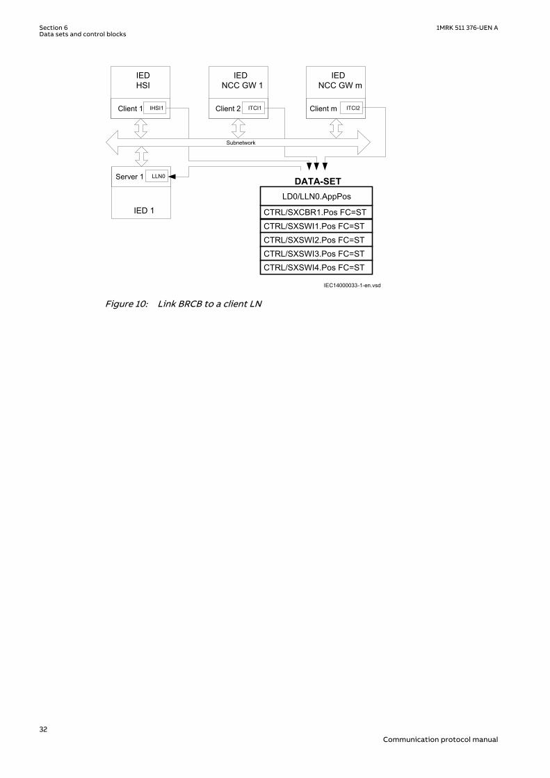
Link BRCB to a client LN
The BRCB has to know to whom the events shall be transmitted. This is the signal routingengineering step. The IEC standard 61850–6 describes that this is given by including the LN ofthe client IED in the ReportBlockEnabled option.
The selected client IED with the corresponding LN, for example, ITCI is included in the SCLstructure of the Report Control description of the IED section.
The description of the BRCB with selected DataSet, configured parameters and selected IEDsis included in the SCL file in the IED section in the LN0 structure for the LD where this LN0belongs to.
1MRK 511 376-UEN A Section 6Data sets and control blocks
31Communication protocol manual
IEC14000033-1-en.vsd
CTRL/SXCBR1.Pos FC=STCTRL/SXSWI1.Pos FC=STCTRL/SXSWI2.Pos FC=STCTRL/SXSWI3.Pos FC=STCTRL/SXSWI4.Pos FC=ST
LD0/LLN0.AppPos
DATA-SET
IEDHSI
Client 1
IEDNCC GW 1
Client 2
IEDNCC GW m
Client m
IED 1
Server 1
Subnetwork
ITCI2ITCI1IHSI1
LLN0
IEC14000033 V1 EN-US
Figure 10: Link BRCB to a client LN
Section 6 1MRK 511 376-UEN AData sets and control blocks
32Communication protocol manual
6.3 GOOSE Control Blocks (GoCB)SEMOD129786-83 v6
en06000109.vsd
Send
Data-set
Rec
eive
Rec
eive
LN
LN
LNLN
LN
Send
Data-set
Rec
eive
Rec
eive
LNLN
LN LN
Send
Data-setR
ecei
ve
Rec
eive
LN
LNLN
LNLN
LN
Subnetwork
LN0
GoCB
DataSet
InputGoCBGoCB
DataSetDataSet
InputInput
Comm.GSE
LD0
Server
LN0
GoCB
DataSet
InputGoCBGoCB
DataSetDataSet
InputInput
Comm.GSE
LD0
Server
IEC06000109 V2 EN-US
Figure 11: IEC 61850: Principle operation of GOOSE messages
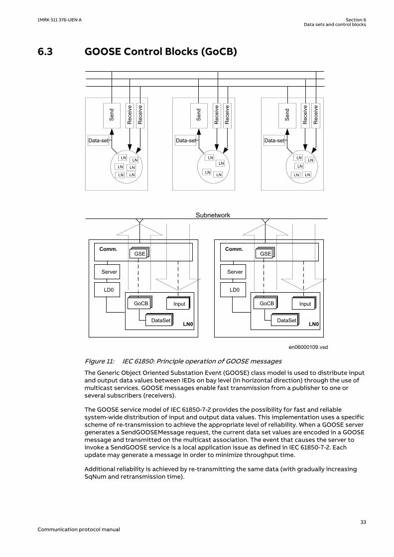
The Generic Object Oriented Substation Event (GOOSE) class model is used to distribute inputand output data values between IEDs on bay level (in horizontal direction) through the use ofmulticast services. GOOSE messages enable fast transmission from a publisher to one orseveral subscribers (receivers).
The GOOSE service model of IEC 61850-7-2 provides the possibility for fast and reliablesystem-wide distribution of input and output data values. This implementation uses a specificscheme of re-transmission to achieve the appropriate level of reliability. When a GOOSE servergenerates a SendGOOSEMessage request, the current data set values are encoded in a GOOSEmessage and transmitted on the multicast association. The event that causes the server toinvoke a SendGOOSE service is a local application issue as defined in IEC 61850-7-2. Eachupdate may generate a message in order to minimize throughput time.
Additional reliability is achieved by re-transmitting the same data (with gradually increasingSqNum and retransmission time).
1MRK 511 376-UEN A Section 6Data sets and control blocks
33Communication protocol manual
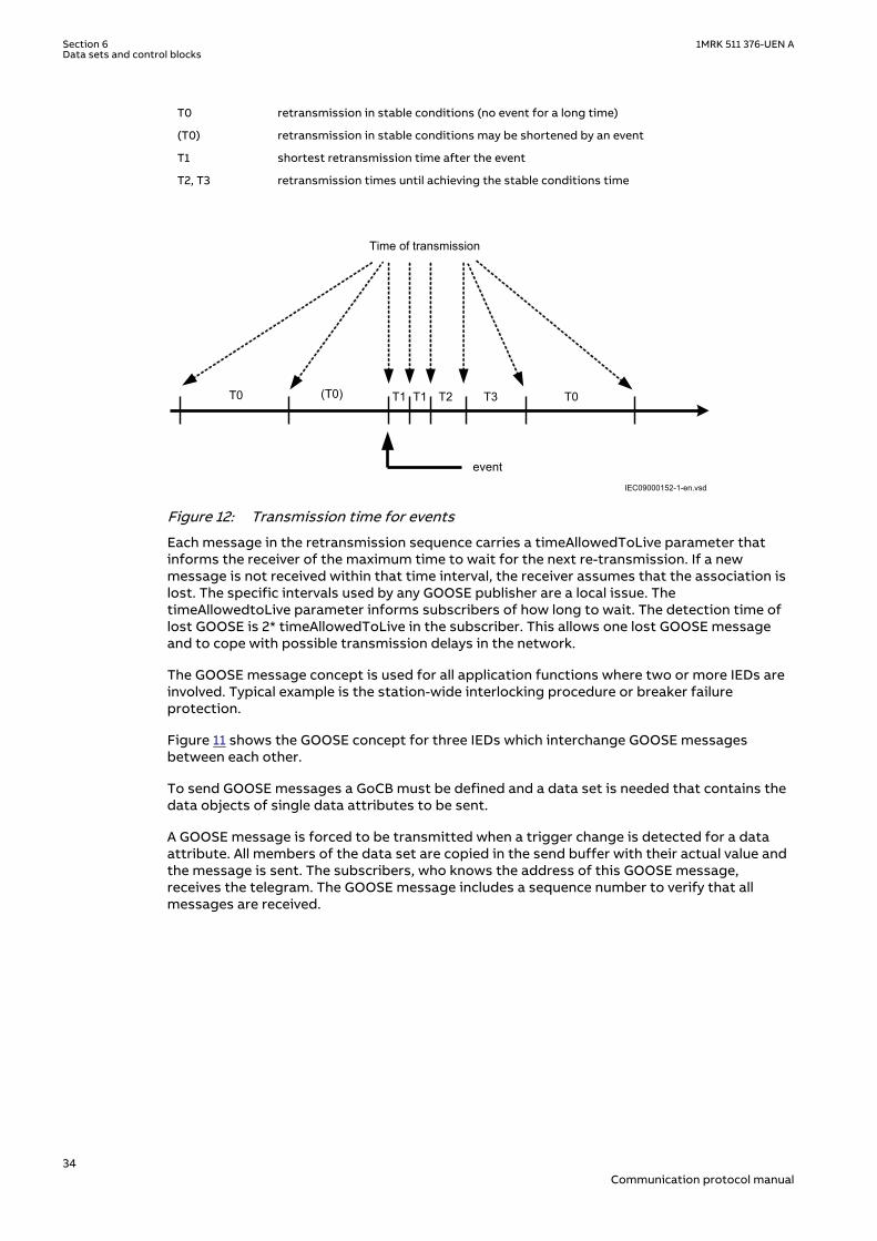
T0 retransmission in stable conditions (no event for a long time)
(T0) retransmission in stable conditions may be shortened by an event
T1 shortest retransmission time after the event
T2, T3 retransmission times until achieving the stable conditions time
Time of transmission
T0 (T0) T1 T1 T2 T3 T0
eventIEC09000152-1-en.vsd
IEC09000152 V1 EN-US
Figure 12: Transmission time for events
Each message in the retransmission sequence carries a timeAllowedToLive parameter thatinforms the receiver of the maximum time to wait for the next re-transmission. If a newmessage is not received within that time interval, the receiver assumes that the association islost. The specific intervals used by any GOOSE publisher are a local issue. ThetimeAllowedtoLive parameter informs subscribers of how long to wait. The detection time oflost GOOSE is 2* timeAllowedToLive in the subscriber. This allows one lost GOOSE messageand to cope with possible transmission delays in the network.
The GOOSE message concept is used for all application functions where two or more IEDs areinvolved. Typical example is the station-wide interlocking procedure or breaker failureprotection.
Figure 11 shows the GOOSE concept for three IEDs which interchange GOOSE messagesbetween each other.
To send GOOSE messages a GoCB must be defined and a data set is needed that contains thedata objects of single data attributes to be sent.
A GOOSE message is forced to be transmitted when a trigger change is detected for a dataattribute. All members of the data set are copied in the send buffer with their actual value andthe message is sent. The subscribers, who knows the address of this GOOSE message,receives the telegram. The GOOSE message includes a sequence number to verify that allmessages are received.
Section 6 1MRK 511 376-UEN AData sets and control blocks
34Communication protocol manual
Section 7 Logical node data model
GUID-EFBB8957-ABA9-4B25-B1CC-630B892A3FC7 v3
The data model used by IEC 61850 is based on logical nodes containing a set of data objects.The data model is defined in the standards.
• IEC 61850-7-4 Compatible logical node classes and data classes• IEC 61850-7-3 Common data classes
The standard describes only classes of logical nodes and data objects on one side andcommon data classes for the data object attributes. Also here it is given has the elements inthese classes are defined as:
• Mandatory (M)• Optional (O)• Conditional optional (Cxxx)• In addition, the IEC 61850 states rules for adding vendor-specific definitions to the
standard, in order to cope with extra functionality.
The possible description of the data model according to the standard allows to adapt a logicalnode of a LN class to that what the product is supporting or using for this LN. This definitionof what parts of a class is used in the actual product and possible addition is called a type,according to IEC 61850-6. There are LN types based upon LN classes. The LN type attributesare called Data Objects (or DATA) and are in of DO types, base upon respective CDC class. Thisallows all partners in the IEC 61850 project who need this LN to understand the LN in all detailsfor the communication part.
The IEC 61850 standard does not describe the functionality and way of operation. Eachsupplier has to describe this separately. ABB has described their function blocks thatrepresent a logical node and all other function blocks in the technical manuals. This chapter inthe communication protocol manual has two purposes:
• Describe the Logical Node types and their data object attribute types.• Make the link to the description of the function block.
7.1 Common data objects in each logical nodeGUID-8400E43A-6199-4539-BB74-CAC865C85508 v3
The IEC 61850 standard describes in part 7-5, a Common Logical Node. The data objectscontained in that LN are both mandatory and optional. The mandatory data objects have to beincluded in each LN. This clause describes the general handling of the data objects in the IEDs.
The mandatory data objects as defined in IEC 61850-7-4 as part of the Common Logical Nodeare Mode, Behavior, Health and NamePlate. Mod, Health and NamePlate are mandatory only inthe root LLN0, and optional in all other LNs.
Mode
Only On and Off are supported on all LNs except for LD0/LLN0, where On, Blocked, Test, andTest-Blocked are supported. Beh can then get all the possible values (On, Blocked, Test, Test-blocked and Off) as a result of Mod on the Root LLN0 and the individual LNs.
The operation modes ON (enabled) and BLOCKED are supported remotely by a command orlocally from the LHMI of the IED.
1MRK 511 376-UEN A Section 7Logical node data model
35Communication protocol manual
If the setting “RemoteModControl” is set to “Off” (default), all remote writes toMod will be rejected.
Behaviour
The operational mode as given by the Mode control is shown in the data object Beh accordingto priority rules described for Beh in clause 6 of IEC 61850-7-4.
The Beh shows the actual state of the function depending on the hierarchy described in clause6 of IEC 61850-7-4.
It is possible that the behavior is influenced also by other sources independent from the Mod,for example Insertion of the test handle, loss of SV, IED configuration tool (PCM600), or LHMI.
In case the setting “operation” of a function is set to Off from the LHMI or PCM600, the Behwill be set to Off independent of the value of the Mod.
The state Off can be set from the LHMI or the PCM600 for the functions having the setting“operation”.
The TEST and the TEST/BLOCKED mode can be operated locally from the LHMI or by usingPCM600.
Health
Health will reflect the current status of the IED HW and configuration. Possible values are: OK,Warning, and Alarm.
Health indicates OK, Warning, or Alarm, depending on the IED status.
NamePlt
The name of the logical node and its relation to namespace definition are shown in the dataobject NamePlt as specified for the SCL structure.
7.2 IEC 61850 data model description Edition 2GUID-B7C6120F-3A98-4DD4-8B4B-CCD2EEC9EE29 v2
The IEC 61850 data model description Edition 2 is delivered in online help format on the IEDConnectivity package DVD as part of the product delivery. The latest versions can bedownloaded from http://www.abb.com/substationautomation.
7.2.1 Using the online help fileGUID-0436EB93-842F-4908-85CB-93BCFED7AC93 v4
1. Download the online help file from this link (1MRK511383-WEN) for IEC 61850 data modeldescription, Edition 2, 650 series 2.1, and save the file to your local hard drive.
2. Double-click the file.3. Clear the Always ask before opening this file check box.4. Click Open.
Section 7 1MRK 511 376-UEN ALogical node data model
36Communication protocol manual

7.2.2 DO presence condition descriptionGUID-63E36A26-DCFF-49CD-9C58-CE783031532C v2
Table 2: Conditions used by the Logical Node description
Condition Description
AtLeastOne At least one of marked elements shall be present.
M Element is mandatory.
MFcond Not yet defined.
Mmulti At least one element shall be present; all instances have an instance number within range[1, 99] (see Part 7-1).
MOrootLD Element is mandatory in the context of a root logical device; otherwise it is optional.
O Element is optional.
Omulti Zero or more elements may be present; all instances have an instance number withinrange [1, 99] (see Part 7-1).
1MRK 511 376-UEN A Section 7Logical node data model
37Communication protocol manual

38
Section 8 Flexible product naming
8.1 IntroductionGUID-98BC22A7-8EFF-4CD0-829E-FBB5D8FD8024 v2
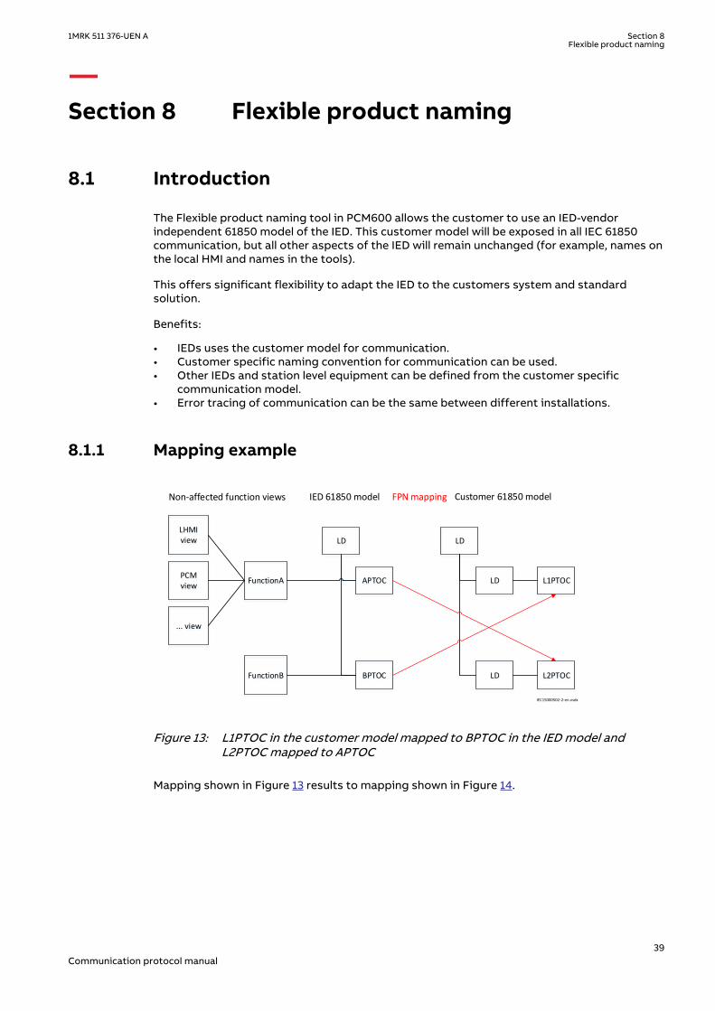
The Flexible product naming tool in PCM600 allows the customer to use an IED-vendorindependent 61850 model of the IED. This customer model will be exposed in all IEC 61850communication, but all other aspects of the IED will remain unchanged (for example, names onthe local HMI and names in the tools).
This offers significant flexibility to adapt the IED to the customers system and standardsolution.
Benefits:
• IEDs uses the customer model for communication.• Customer specific naming convention for communication can be used.• Other IEDs and station level equipment can be defined from the customer specific
communication model.• Error tracing of communication can be the same between different installations.
8.1.1 Mapping exampleGUID-DD7F097C-1D72-4BA2-8684-61B54EF0D00C v1
FunctionA
Non-affected function views IED 61850 model Customer 61850 modelFPN mapping
FunctionB
LHMI view
PCM view
... view
LD
APTOC
BPTOC
LD
L1PTOC
L2PTOC
LD
LD
IEC15000502-2-en.vsdx
IEC15000502 V2 EN-US
Figure 13: L1PTOC in the customer model mapped to BPTOC in the IED model andL2PTOC mapped to APTOC
Mapping shown in Figure 13 results to mapping shown in Figure 14.
1MRK 511 376-UEN A Section 8Flexible product naming
39Communication protocol manual
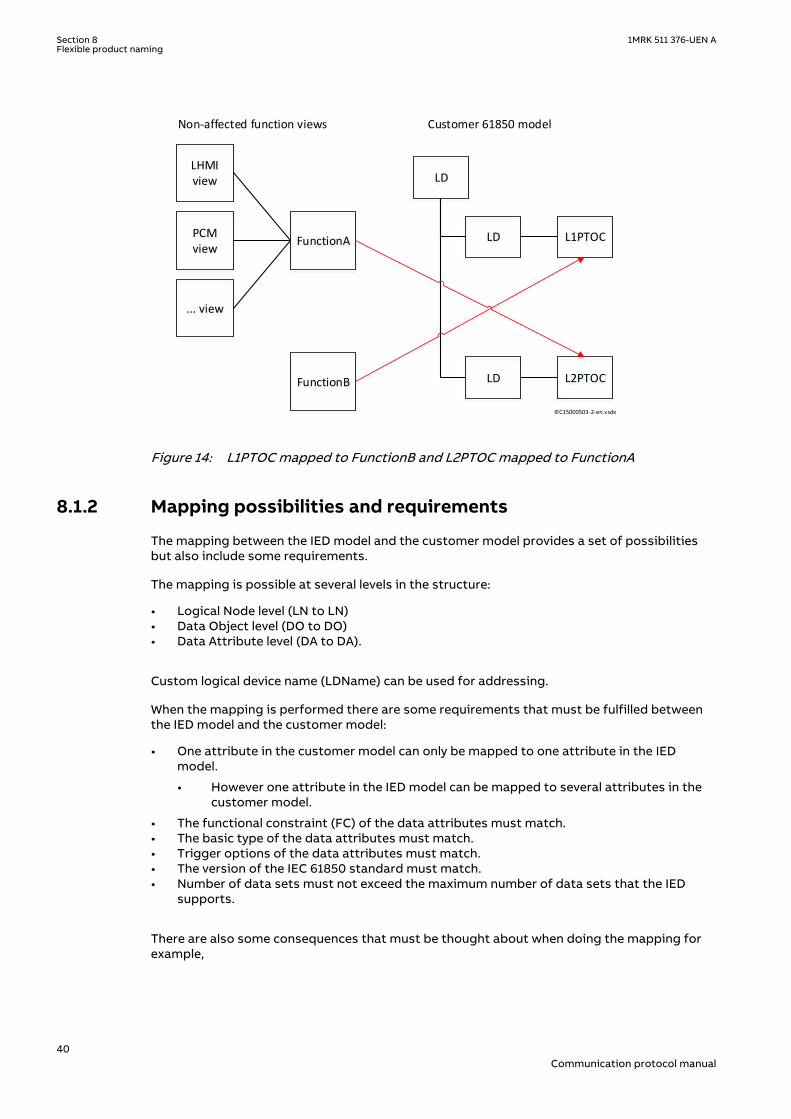
FunctionA
Non-affected function views
FunctionB
LHMI view
PCM view
... view
LD
L1PTOC
L2PTOC
LD
LD
Customer 61850 model
IEC15000503-2-en.vsdx
IEC15000503 V2 EN-US
Figure 14: L1PTOC mapped to FunctionB and L2PTOC mapped to FunctionA
8.1.2 Mapping possibilities and requirementsGUID-AA4E0570-D874-4B82-84A5-729644C67626 v1
The mapping between the IED model and the customer model provides a set of possibilitiesbut also include some requirements.
The mapping is possible at several levels in the structure:
• Logical Node level (LN to LN)• Data Object level (DO to DO)• Data Attribute level (DA to DA).
Custom logical device name (LDName) can be used for addressing.
When the mapping is performed there are some requirements that must be fulfilled betweenthe IED model and the customer model:
• One attribute in the customer model can only be mapped to one attribute in the IEDmodel.
• However one attribute in the IED model can be mapped to several attributes in thecustomer model.
• The functional constraint (FC) of the data attributes must match.• The basic type of the data attributes must match.• Trigger options of the data attributes must match.• The version of the IEC 61850 standard must match.• Number of data sets must not exceed the maximum number of data sets that the IED
supports.
There are also some consequences that must be thought about when doing the mapping forexample,
Section 8 1MRK 511 376-UEN AFlexible product naming
40Communication protocol manual

• If two DOs in one LN in the customer model are mapped to DOs in different LNs in the IEDmodel the DOs in the customer model might be inconsistent with respect to quality in thecase of different operational states of the IED Functions.
• When several LNs in the customer model are mapped to one function in the IED, the Modof the function will affect all the customer LNs
Several other use cases like this exist. By understanding the concept of mapping from IEDfunctions and IED model to customer model, these cases can be foreseen.
1MRK 511 376-UEN A Section 8Flexible product naming
41Communication protocol manual

42
Section 9 Glossary
9.1 GlossaryM14893-1 v15
AC Alternating current
ACC Actual channel
ACT Application configuration tool within PCM600
A/D converter Analog-to-digital converter
ADBS Amplitude deadband supervision
ADM Analog digital conversion module, with time synchronization
AI Analog input
ANSI American National Standards Institute
AR Autoreclosing
ASCT Auxiliary summation current transformer
ASD Adaptive signal detection
ASDU Application service data unit
AWG American Wire Gauge standard
BBP Busbar protection
BFOC/2,5 Bayonet fiber optic connector
BFP Breaker failure protection
BI Binary input
BIM Binary input module
BOM Binary output module
BOS Binary outputs status
BR External bistable relay
BS British Standards
BSR Binary signal transfer function, receiver blocks
BST Binary signal transfer function, transmit blocks
C37.94 IEEE/ANSI protocol used when sending binary signals between IEDs
CAN Controller Area Network. ISO standard (ISO 11898) for serialcommunication
CB Circuit breaker
CBM Combined backplane module
CCITT Consultative Committee for International Telegraph and Telephony. AUnited Nations-sponsored standards body within the InternationalTelecommunications Union.
CCM CAN carrier module
CCVT Capacitive Coupled Voltage Transformer
Class C Protection Current Transformer class as per IEEE/ ANSI
1MRK 511 376-UEN A Section 9Glossary
43Communication protocol manual
CMPPS Combined megapulses per second
CMT Communication Management tool in PCM600
CO cycle Close-open cycle
Codirectional Way of transmitting G.703 over a balanced line. Involves two twistedpairs making it possible to transmit information in both directions
COM Command
COMTRADE Standard Common Format for Transient Data Exchange format forDisturbance recorder according to IEEE/ANSI C37.111, 1999 / IEC60255-24
Contra-directional Way of transmitting G.703 over a balanced line. Involves four twistedpairs, two of which are used for transmitting data in both directionsand two for transmitting clock signals
COT Cause of transmission
CPU Central processing unit
CR Carrier receive
CRC Cyclic redundancy check
CROB Control relay output block
CS Carrier send
CT Current transformer
CU Communication unit
CVT or CCVT Capacitive voltage transformer
DAR Delayed autoreclosing
DARPA Defense Advanced Research Projects Agency (The US developer of theTCP/IP protocol etc.)
DBDL Dead bus dead line
DBLL Dead bus live line
DC Direct current
DFC Data flow control
DFT Discrete Fourier transform
DHCP Dynamic Host Configuration Protocol
DIP-switch Small switch mounted on a printed circuit board
DI Digital input
DLLB Dead line live bus
DNP Distributed Network Protocol as per IEEE Std 1815-2012
DR Disturbance recorder
DRAM Dynamic random access memory
DRH Disturbance report handler
DSP Digital signal processor
DTT Direct transfer trip scheme
EHV network Extra high voltage network
EIA Electronic Industries Association
EMC Electromagnetic compatibility
Section 9 1MRK 511 376-UEN AGlossary
44Communication protocol manual
EMF Electromotive force
EMI Electromagnetic interference
EnFP End fault protection
EPA Enhanced performance architecture
ESD Electrostatic discharge
F-SMA Type of optical fiber connector
FAN Fault number
FCB Flow control bit; Frame count bit
FOX 20 Modular 20 channel telecommunication system for speech, data andprotection signals
FOX 512/515 Access multiplexer
FOX 6Plus Compact time-division multiplexer for the transmission of up to sevenduplex channels of digital data over optical fibers
FTP File Transfer Protocol
FUN Function type
G.703 Electrical and functional description for digital lines used by localtelephone companies. Can be transported over balanced andunbalanced lines
GCM Communication interface module with carrier of GPS receiver module
GDE Graphical display editor within PCM600
GI General interrogation command
GIS Gas-insulated switchgear
GOOSE Generic object-oriented substation event
GPS Global positioning system
GSAL Generic security application
GSE Generic substation event
HDLC protocol High-level data link control, protocol based on the HDLC standard
HFBR connector type Plastic fiber connector
HMI Human-machine interface
HSAR High speed autoreclosing
HV High-voltage
HVDC High-voltage direct current
IDBS Integrating deadband supervision
IEC International Electrical Committee
IEC 60044-6 IEC Standard, Instrument transformers – Part 6: Requirements forprotective current transformers for transient performance
IEC 60870-5-103 Communication standard for protection equipment. A serial master/slave protocol for point-to-point communication
IEC 61850 Substation automation communication standard
IEC 61850–8–1 Communication protocol standard
IEEE Institute of Electrical and Electronics Engineers
IEEE 802.12 A network technology standard that provides 100 Mbits/s on twisted-pair or optical fiber cable
1MRK 511 376-UEN A Section 9Glossary
45Communication protocol manual
IEEE P1386.1 PCI Mezzanine Card (PMC) standard for local bus modules. Referencesthe CMC (IEEE P1386, also known as Common Mezzanine Card)standard for the mechanics and the PCI specifications from the PCI SIG(Special Interest Group) for the electrical EMF (Electromotive force).
IEEE 1686 Standard for Substation Intelligent Electronic Devices (IEDs) CyberSecurity Capabilities
IED Intelligent electronic device
I-GIS Intelligent gas-insulated switchgear
IOM Binary input/output module
Instance When several occurrences of the same function are available in the IED,they are referred to as instances of that function. One instance of afunction is identical to another of the same kind but has a differentnumber in the IED user interfaces. The word "instance" is sometimesdefined as an item of information that is representative of a type. Inthe same way an instance of a function in the IED is representative of atype of function.
IP 1. Internet protocol. The network layer for the TCP/IP protocol suitewidely used on Ethernet networks. IP is a connectionless, best-effortpacket-switching protocol. It provides packet routing, fragmentationand reassembly through the data link layer.2. Ingression protection, according to IEC 60529
IP 20 Ingression protection, according to IEC 60529, level 20
IP 40 Ingression protection, according to IEC 60529, level 40
IP 54 Ingression protection, according to IEC 60529, level 54
IRF Internal failure signal
IRIG-B: InterRange Instrumentation Group Time code format B, standard 200
ITU International Telecommunications Union
LAN Local area network
LIB 520 High-voltage software module
LCD Liquid crystal display
LDCM Line differential communication module
LDD Local detection device
LED Light-emitting diode
LNT LON network tool
LON Local operating network
MCB Miniature circuit breaker
MCM Mezzanine carrier module
MPM Main processing module
MVAL Value of measurement
MVB Multifunction vehicle bus. Standardized serial bus originally developedfor use in trains.
NCC National Control Centre
NOF Number of grid faults
NUM Numerical module
OCO cycle Open-close-open cycle
Section 9 1MRK 511 376-UEN AGlossary
46Communication protocol manual
OCP Overcurrent protection
OEM Optical Ethernet module
OLTC On-load tap changer
OTEV Disturbance data recording initiated by other event than start/pick-up
OV Overvoltage
Overreach A term used to describe how the relay behaves during a fault condition.For example, a distance relay is overreaching when the impedancepresented to it is smaller than the apparent impedance to the faultapplied to the balance point, that is, the set reach. The relay “sees” thefault but perhaps it should not have seen it.
PCI Peripheral component interconnect, a local data bus
PCM Pulse code modulation
PCM600 Protection and control IED manager
PC-MIP Mezzanine card standard
PMC PCI Mezzanine card
POR Permissive overreach
POTT Permissive overreach transfer trip
Process bus Bus or LAN used at the process level, that is, in near proximity to themeasured and/or controlled components
PSM Power supply module
PST Parameter setting tool within PCM600
PT ratio Potential transformer or voltage transformer ratio
PUTT Permissive underreach transfer trip
RASC Synchrocheck relay, COMBIFLEX
RCA Relay characteristic angle
RISC Reduced instruction set computer
RMS value Root mean square value
RS422 A balanced serial interface for the transmission of digital data in point-to-point connections
RS485 Serial link according to EIA standard RS485
RTC Real-time clock
RTU Remote terminal unit
SA Substation Automation
SBO Select-before-operate
SC Switch or push button to close
SCL Short circuit location
SCS Station control system
SCADA Supervision, control and data acquisition
SCT System configuration tool according to standard IEC 61850
SDU Service data unit
SLM Serial communication module.
SMA connector Subminiature version A, A threaded connector with constantimpedance.
1MRK 511 376-UEN A Section 9Glossary
47Communication protocol manual

SMT Signal matrix tool within PCM600
SMS Station monitoring system
SNTP Simple network time protocol – is used to synchronize computer clockson local area networks. This reduces the requirement to have accuratehardware clocks in every embedded system in a network. Eachembedded node can instead synchronize with a remote clock,providing the required accuracy.
SOF Status of fault
SPA Strömberg Protection Acquisition (SPA), a serial master/slave protocolfor point-to-point and ring communication.
SRY Switch for CB ready condition
ST Switch or push button to trip
Starpoint Neutral point of transformer or generator
SVC Static VAr compensation
TC Trip coil
TCS Trip circuit supervision
TCP Transmission control protocol. The most common transport layerprotocol used on Ethernet and the Internet.
TCP/IP Transmission control protocol over Internet Protocol. The de factostandard Ethernet protocols incorporated into 4.2BSD Unix. TCP/IPwas developed by DARPA for Internet working and encompasses bothnetwork layer and transport layer protocols. While TCP and IP specifytwo protocols at specific protocol layers, TCP/IP is often used to referto the entire US Department of Defense protocol suite based uponthese, including Telnet, FTP, UDP and RDP.
TEF Time delayed earth-fault protection function
TLS Transport Layer Security
TM Transmit (disturbance data)
TNC connector Threaded Neill-Concelman, a threaded constant impedance version of aBNC connector
TP Trip (recorded fault)
TPZ, TPY, TPX, TPS Current transformer class according to IEC
TRM Transformer Module. This module transforms currents and voltagestaken from the process into levels suitable for further signalprocessing.
TYP Type identification
UMT User management tool
Underreach A term used to describe how the relay behaves during a fault condition.For example, a distance relay is underreaching when the impedancepresented to it is greater than the apparent impedance to the faultapplied to the balance point, that is, the set reach. The relay does not“see” the fault but perhaps it should have seen it. See also Overreach.
UTC Coordinated Universal Time. A coordinated time scale, maintained bythe Bureau International des Poids et Mesures (BIPM), which forms thebasis of a coordinated dissemination of standard frequencies and timesignals. UTC is derived from International Atomic Time (TAI) by theaddition of a whole number of "leap seconds" to synchronize it withUniversal Time 1 (UT1), thus allowing for the eccentricity of the Earth'sorbit, the rotational axis tilt (23.5 degrees), but still showing the Earth's
Section 9 1MRK 511 376-UEN AGlossary
48Communication protocol manual

irregular rotation, on which UT1 is based. The Coordinated UniversalTime is expressed using a 24-hour clock, and uses the Gregoriancalendar. It is used for aeroplane and ship navigation, where it is alsosometimes known by the military name, "Zulu time." "Zulu" in thephonetic alphabet stands for "Z", which stands for longitude zero.
UV Undervoltage
WEI Weak end infeed logic
VT Voltage transformer
3IO Three times zero-sequence current.Often referred to as the residual orthe earth-fault current
3UO Three times the zero sequence voltage. Often referred to as theresidual voltage or the neutral point voltage
1MRK 511 376-UEN A Section 9Glossary
49Communication protocol manual

50

51

ABB ABSubstation Automation ProductsSE-721 59 Västerås, SwedenPhone +46 (0) 21 32 50 00
www.abb.com/protection-control
© Copyright 2016 ABB.All rights reserved.
Scan this QR code to visit our website
1MR
K 5
11 3
76-U
EN