a thermal casing connection test to avoid casing failure ... · pt. citra tubindo tbk (ptct), a...
TRANSCRIPT
Proceedings World Geothermal Congress 2020
Reykjavik, Iceland, April 26 – May 2, 2020
1
A Thermal Casing Connection Test to Avoid Casing Failure in Geothermal Wells
M. Fahmi.Sungkar1, Hendra Simanjuntak1, Boga Isa2
1PT. Citra Tubindo Tbk
2Geothermal Drilling Consultant
e-mail: [email protected]; [email protected]
Keywords: Drilling, casing connection test, thermal cycle, production casing, geothermal well, TWCCEP, casing design, casing
failure, thermal casing failure
ABSTRACT
Determining the proper casing and its connection for geothermal wells is very crucial. The casing and its connection experience
various loads not only during drilling operations but also during production operations. In the past, there were numerous papers
published in relation to casing failures in geothermal wells that sometime is hardly explained. For more than 100 years of geothermal
experience, geothermal wells are still designed driven by oil and gas practices including the selection of casing and its connection.
There is no specific protocol or procedure on how to determine suitable casing especially on selecting the casing connection to avoid
casing failure especially during production operations due to thermal loads. In geothermal, the thermal load caused by the temperature
cycle is potentially the highest load experienced by the production casing and its connection. This paper presents the testing protocol
used to qualify the 13-3/8”, 68#, L80 Type 1 with NS-CC Connection, an API interchangeable connection, that used for Production
Casing which believe as the critical casing for geothermal well. The testing protocol is referred to the ISO/PAS 12835:2013, Thermal
Well Casing Connection Evaluation Protocol (TWCCEP) with some abbreviation, that have been used for high temperature wells in
oil and gas industry, Cyclic Steam Stimulation (CSS) and Steam Assisted Gravity Drainage (SAGD). The test was conducted using
2+2 casing specimens at PT Citra Tubindo testing facility in Batam, Indonesia. Total of 30 thermal load cycles at temperature range
of 35º – 290º C have been used to anticipate geothermal well lifetime and this have surpassed the original protocol. This paper
summarizes the testing process from beginning to the end and the successful testing result of the NS-CC Premium casing connection.
1. INTRODUCTION
PT. Citra Tubindo Tbk (PTCT), a subsidiary of Vallourec Group, have been one of the main casing suppliers for Oil and Gas and
Geothermal Business in Indonesia. Since 2014, PTCT have supplied casing from 20” size down to 7” sizes for more than 24
geothermal wells in Indonesia. Uniquely, a Production Casing with NS-CC connection was supplied based on experienced of the
engineer who have used the connection for deepwater well application. NS-CC Connection is a premium gas tight connection that
has a same performance as the pipe body, which was considered as a suitable connection to handle thermal loads for geothermal wells
application to avoid casing failure. One of the challenges in geothermal application is the reservoir condition where the steam
production temperature could be up to 350º C during its production operations. The other challenge is to have casing integrity during
well lifetime that could be more than 30 years. To provide assurance for supply of Production Casing with NS-CC connection, PTCT
has conducted a Thermal Casing Connection Test using 13-3/8” 68# L80 Type 1 NS-CC connection at Connection Development &
Evaluation Center (CDEC) facility in Batam. CDEC facility is PTCT inhouse tubular testing facility that can simulate a testing
protocol based on ISO 13679, API 5C5, or ISO: PAS 12835:2013 TWCCEP. The objective of this technical paper is to report the
qualification test conducted to NS-CC Premium Connection from beginning to the end. The Thermal Casing Connection Test was
conducted for total duration of approximately 6 months and funded by PTCT.
2. WHAT IS TWCCEP?
Casing connections in thermal wells experience extreme loads due to exposure of high temperatures steam between 180ºC-350ºC in
cemented condition. Thermal Well Casing Connection Evaluation Protocol (TWCCEP) was published as ISO Publicly Available
Specification (PAS) 12835 on 2013–12-15 purposely for oil and gas industry.
TWCCEP provides procedures for assessing the suitability of threaded connections for service in intermediate or production casing
strings of thermal recovery wells initially for Cyclic Steam Stimulation (CSS) and Steam Assisted Gravity Drainage (SAGD).
TWCCEP has been developed through a multi-client project (MCP), coordinated by Noetic Engineering 2008 Inc (Noetic) and
sponsored by oil and gas operators and connection manufacturers involved in thermal-well operations in Canada. TWCCEP is
intended for connection assessments for strain-based design applications. It is not intended for elastic-design applications addressed
by ISO 13679 and API 5C5.
The thermal casing connection test was conducted as part of assurance for supply of Production Casing with NS-CC connection. 30
thermal load cycles with ASL 290 are chosen to simulate the test conditions.
3. GEOTHERMAL WELL DESIGN
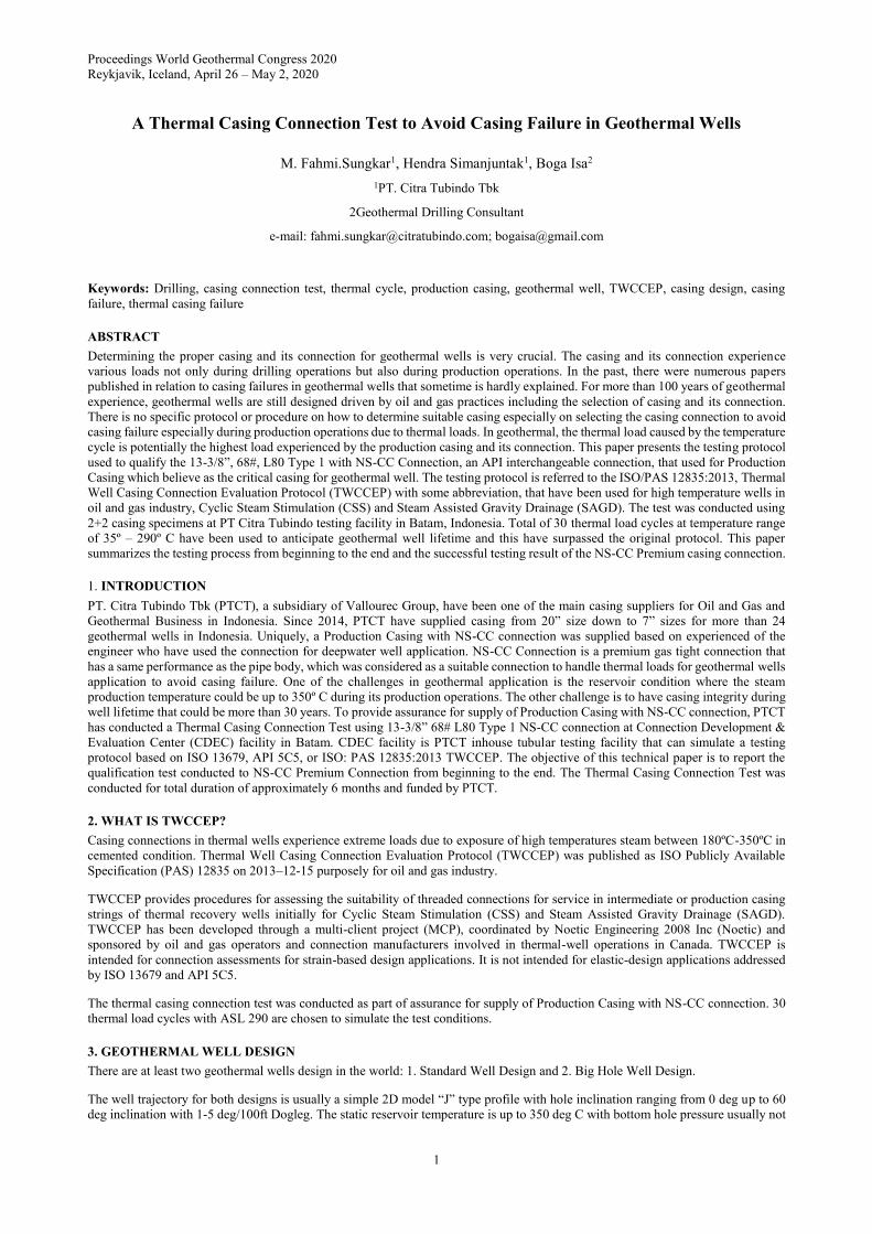
There are at least two geothermal wells design in the world: 1. Standard Well Design and 2. Big Hole Well Design.
The well trajectory for both designs is usually a simple 2D model “J” type profile with hole inclination ranging from 0 deg up to 60
deg inclination with 1-5 deg/100ft Dogleg. The static reservoir temperature is up to 350 deg C with bottom hole pressure usually not
Sungkar et al.
2
exceeding 1000 psi at the surface. Multiple fractures are anticipated when drilling the reservoir section covered by perforated
production casing liner where drilling with losses is anticipated.
Figure 1: Geothermal Well Design.
The production casing (13-3/8” casing for Big Hole and 9-5/8” casing for Standard Hole) is the casing that experienced the highest
load during production operations. There are at least three activity that resulting different temperature range: Shut in, Flowing and
Injection. This gives an axial load cycling that cause production casing in compression or in tension mode that may result casing
failure. Failure in selecting the right type casing connection could cause casing or connection problem that lead to losing the well
integrity, hence create catastrophic condition and ultimately losing the revenue.
4. QUALIFICATION CONTEXT
4.1 Testing Procedure and Reference Documents
The testing procedure was developed by PTCT. An Official Testing Procedure (OTP) number VRCC 18-0204 that refer to ISO: PAS
12835:2013 TWCCEP protocol with several abbreviation was finalized with highlights as following:
1. Two sealability test sampel with 2 spare sample are prepared based on TWCCEP 1.3 Worst Case configuration, WST
(Worst Sealability on Tension at low temperature) and WSC (Worst-case for Sealability in Compression at high
temperature).
2. Total of 30 Thermal cycle is targeted insted of 10 Thermal Cycle (exceed TWCCEP requirements).
3. Optional Bending Test represented by Task 4.3 of the TWCCEP is not performed, since the 13-3/8” NS-CC Connection
has already been evaluated on bending as per ISO 13679.
4. Limit Strain Test to be performed as per Task 4.4
5. Temperature tolerance during hold times is ± 15ºC both on Pipe body and Coupling.
6. A maximum of 6 thermocouples to be placedd on to monitor the temperature. No insulation method is used during testing.
7. No strain gauges to be placed on test samples.
8. Both test sample to be tested separately.
Sungkar et al
3
Table 1: Main Conditions of Testing.
Application severity
level ASL 290
Galling resistance test 2x Make & Break
Thermal Cycle (30x) 290ºC, maintain at zero
strain
Limit Strain Test
Tension to failure (exceed
the tensile strain
threshold)
4.2 Connection Main Characteristic
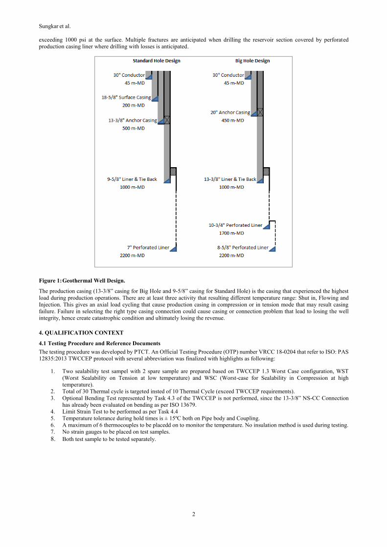
NS-CC (NS Connection for Casing) is PTCT Proprietary Thread and Coupled (T&C) Gas Tight Connection providing the most field
worthy tubular for oil and gas and geothermal application. This connection is also interchangeable with API BTC connection which
give more flexibility on selecting the casing accessories. On Figure 2 we can found NS-CC Connection Design and Dimension for
13-3/8” pipes with 68 pound per foot (ppf/#).
Figure 2: NS-CC Connection Design and Dimension.
NS-CC is a high performance gas-tight connection for a critical environments such as high compression, bending, fatigue resistance.
The “Two-Step pin nose” allows the metal to metal seal to be protected from running, over torque damage, and also provide a high
compression performance. NS-CC connection have a flush ID Design, which very important to prevent localized erosion that could
lead to actual destruction of the connection. NS-CC is rated 100% Pipe Body Yield in Tension, Compression, Internal, and External
Pressure, making its the best choice for Thermal Well application. NS-CC Performance on 13-3/8” 68# L80 Type 1 could be found
on Table 2.
Connection Dimension
Pipe ID 12.415”
Pin ID 12.429”
Coupling ID 12.392
Coupling OD 14.375”
Coupling Length 11.870”
Pin Lc Length 2.9553”
Wall Thickness 0.480”
Drift Diameter 12.259”
Sungkar et al.
4
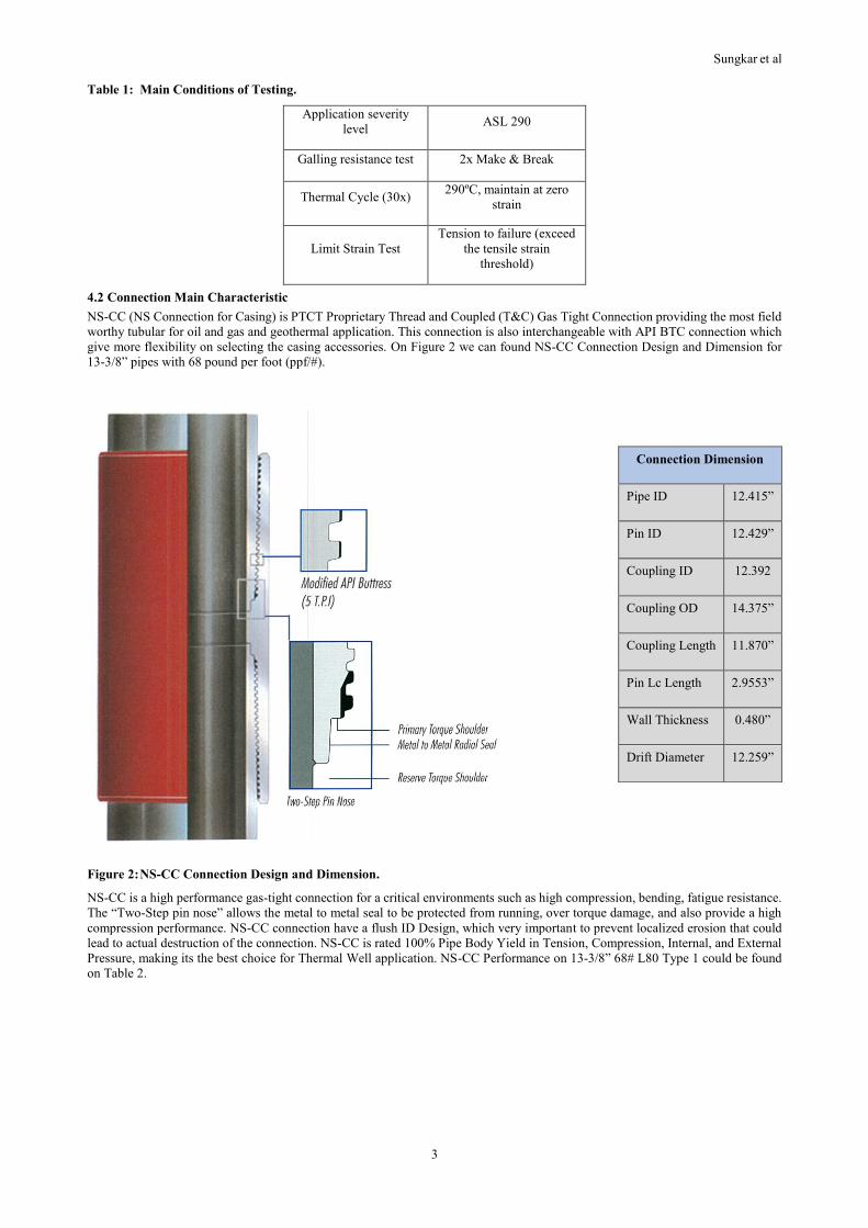
Table 2: 13-3/8” 68# L80 Type 1 NS-CC Performance.
Connection Performance Make up Torque
Tension
(klb)
Comp
(klb)
Burst
(psi)
Collapse
(psi)
Min
(lb-ft)
Opt
(lb-ft)
Max
(lb-ft)
1,545 1,545 5,020 2,260 12,300 14,100 15,900
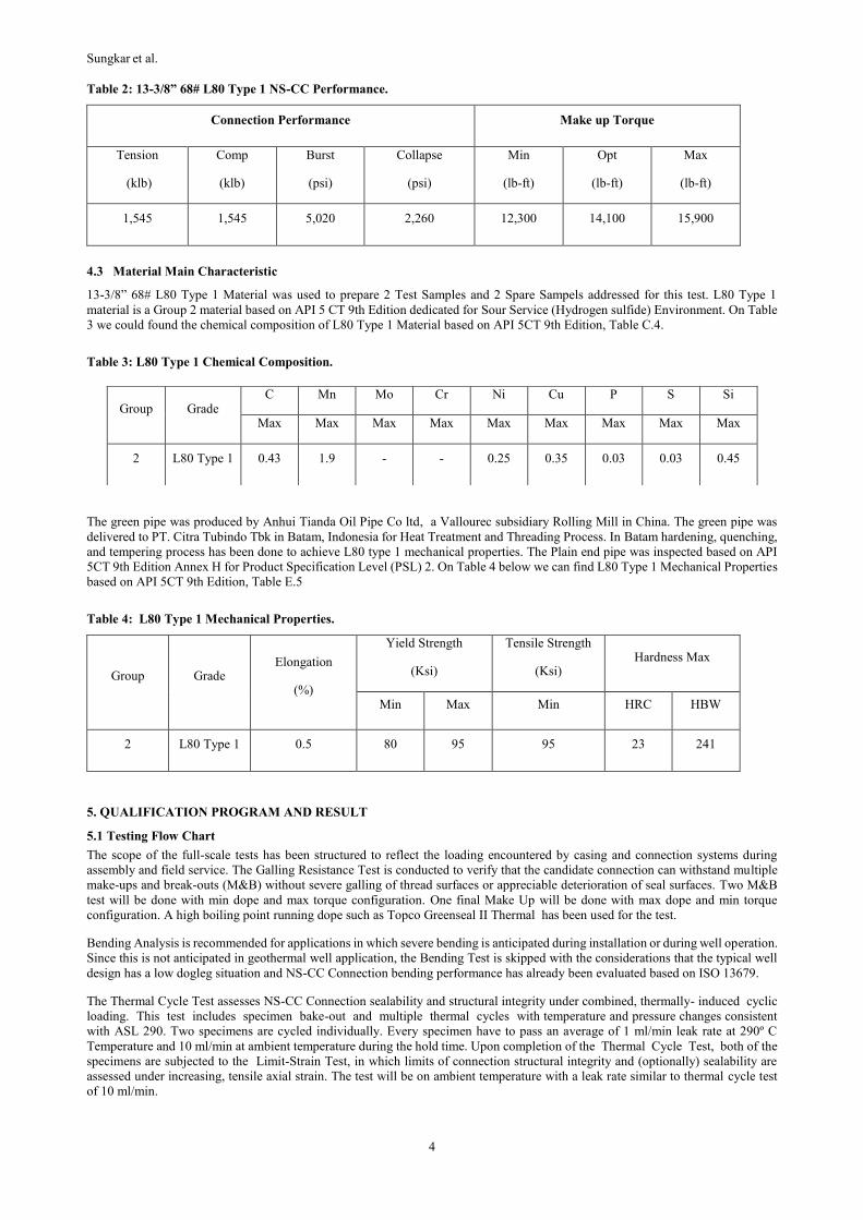
4.3 Material Main Characteristic
13-3/8” 68# L80 Type 1 Material was used to prepare 2 Test Samples and 2 Spare Sampels addressed for this test. L80 Type 1
material is a Group 2 material based on API 5 CT 9th Edition dedicated for Sour Service (Hydrogen sulfide) Environment. On Table
3 we could found the chemical composition of L80 Type 1 Material based on API 5CT 9th Edition, Table C.4.
Table 3: L80 Type 1 Chemical Composition.
The green pipe was produced by Anhui Tianda Oil Pipe Co ltd, a Vallourec subsidiary Rolling Mill in China. The green pipe was
delivered to PT. Citra Tubindo Tbk in Batam, Indonesia for Heat Treatment and Threading Process. In Batam hardening, quenching,
and tempering process has been done to achieve L80 type 1 mechanical properties. The Plain end pipe was inspected based on API
5CT 9th Edition Annex H for Product Specification Level (PSL) 2. On Table 4 below we can find L80 Type 1 Mechanical Properties
based on API 5CT 9th Edition, Table E.5
Table 4: L80 Type 1 Mechanical Properties.
Group Grade Elongation
(%)
Yield Strength
(Ksi)
Tensile Strength
(Ksi) Hardness Max
Min Max Min HRC HBW
2 L80 Type 1 0.5 80 95 95 23 241
5. QUALIFICATION PROGRAM AND RESULT
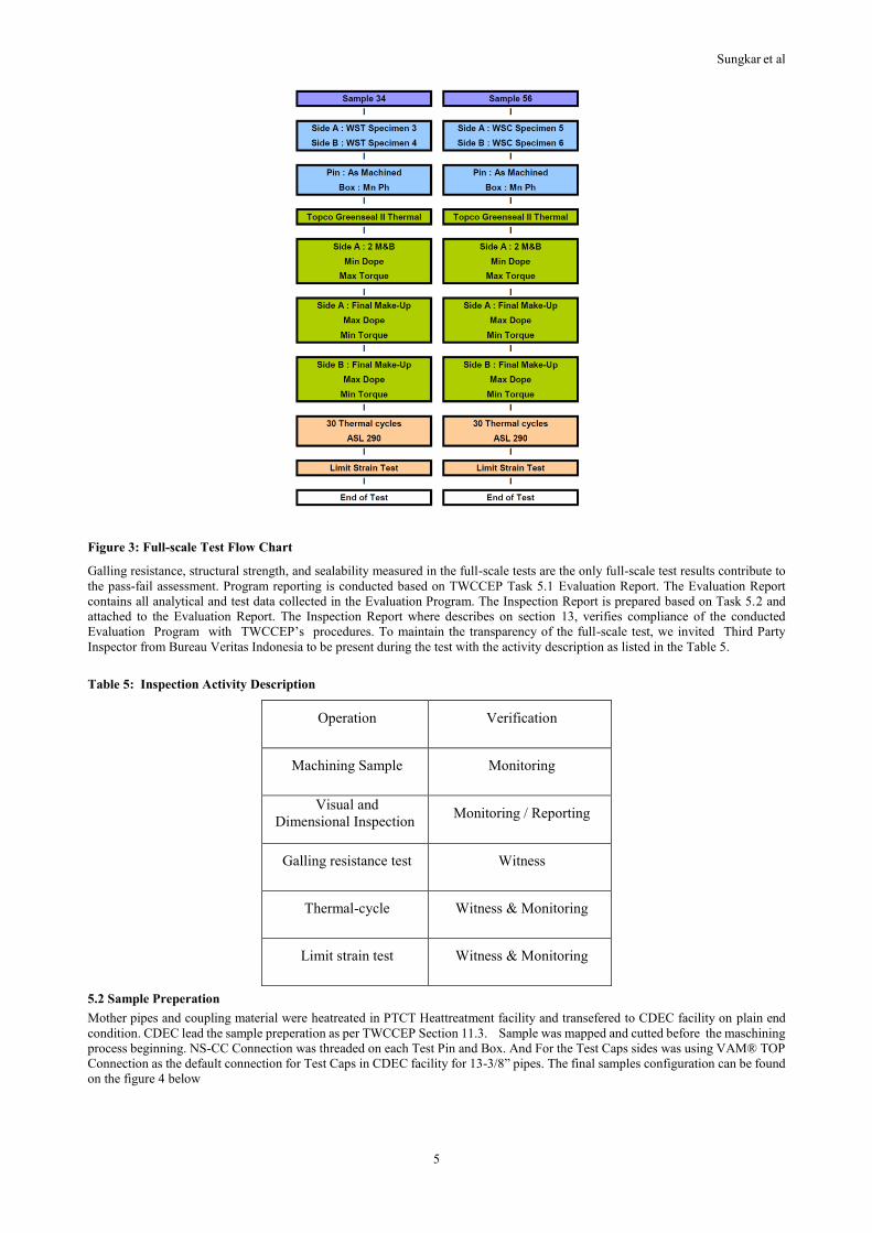
5.1 Testing Flow Chart
The scope of the full-scale tests has been structured to reflect the loading encountered by casing and connection systems during
assembly and field service. The Galling Resistance Test is conducted to verify that the candidate connection can withstand multiple
make-ups and break-outs (M&B) without severe galling of thread surfaces or appreciable deterioration of seal surfaces. Two M&B
test will be done with min dope and max torque configuration. One final Make Up will be done with max dope and min torque
configuration. A high boiling point running dope such as Topco Greenseal II Thermal has been used for the test.
Bending Analysis is recommended for applications in which severe bending is anticipated during installation or during well operation.
Since this is not anticipated in geothermal well application, the Bending Test is skipped with the considerations that the typical well
design has a low dogleg situation and NS-CC Connection bending performance has already been evaluated based on ISO 13679.
The Thermal Cycle Test assesses NS-CC Connection sealability and structural integrity under combined, thermally- induced cyclic
loading. This test includes specimen bake-out and multiple thermal cycles with temperature and pressure changes consistent
with ASL 290. Two specimens are cycled individually. Every specimen have to pass an average of 1 ml/min leak rate at 290º C
Temperature and 10 ml/min at ambient temperature during the hold time. Upon completion of the Thermal Cycle Test, both of the
specimens are subjected to the Limit-Strain Test, in which limits of connection structural integrity and (optionally) sealability are
assessed under increasing, tensile axial strain. The test will be on ambient temperature with a leak rate similar to thermal cycle test
of 10 ml/min.
Group Grade C Mn Mo Cr Ni Cu P S Si
Max Max Max Max Max Max Max Max Max
2 L80 Type 1 0.43 1.9 - - 0.25 0.35 0.03 0.03 0.45
Sungkar et al
5
Figure 3: Full-scale Test Flow Chart
Galling resistance, structural strength, and sealability measured in the full-scale tests are the only full-scale test results contribute to
the pass-fail assessment. Program reporting is conducted based on TWCCEP Task 5.1 Evaluation Report. The Evaluation Report
contains all analytical and test data collected in the Evaluation Program. The Inspection Report is prepared based on Task 5.2 and
attached to the Evaluation Report. The Inspection Report where describes on section 13, verifies compliance of the conducted
Evaluation Program with TWCCEP’s procedures. To maintain the transparency of the full-scale test, we invited Third Party
Inspector from Bureau Veritas Indonesia to be present during the test with the activity description as listed in the Table 5.
Table 5: Inspection Activity Description
Operation Verification
Machining Sample Monitoring
Visual and
Dimensional Inspection Monitoring / Reporting
Galling resistance test Witness
Thermal-cycle Witness & Monitoring
Limit strain test Witness & Monitoring
5.2 Sample Preperation
Mother pipes and coupling material were heatreated in PTCT Heattreatment facility and transefered to CDEC facility on plain end
condition. CDEC lead the sample preperation as per TWCCEP Section 11.3. Sample was mapped and cutted before the maschining
process beginning. NS-CC Connection was threaded on each Test Pin and Box. And For the Test Caps sides was using VAM® TOP
Connection as the default connection for Test Caps in CDEC facility for 13-3/8” pipes. The final samples configuration can be found
on the figure 4 below

Sungkar et al.
6
Figure 4: Samples Layout and Marking.
5.2.1 Sample Machining
FEA simulation can identify the worst-case scenarios on metal to metal seal and threads. Mainly the connection taper, threads
interferences, and seal interference are the targets. Vallourec R&D departement in France ran a simulation on nominal case and the
they ran additional simulations to simulate different taper or interferences configurations and compare them to the reference.
The worst configuration from all 3 aspects will be chosen for the tested specimens. The worst-case specimen configurations are as
follows:
1. Worst-case for sealability in tension at low temperature (WST).
2. Worst-case for sealability in compression at high temperature (WSC).
Table 6: Specimen Worst-case Configuration
Specimen Seal Interference Thread Interference Taper
WST Min Max Pin Slow / Box Fast (PSBF)
WSC Min Max Pin Slow / Box Fast (PSBF)
5.2.2 Connection End Finishing
The end finishing for NS-CC Connection has folowed the Surface treatment procedure of TS-06 for Carbon Steel material. NS-CC
Pin side was left as machined and the Box side has a Manganese Phosphate treatment to improve its galling resistance .
5.2.3 Port Holes
In order to evaluate the sealability performance of connection metal to metal seal, two port holes were drilled on the coupling of test
samples, according to TWCCEP 1.3, Section 12.1.4. The port holes were drilled on the coupling for each pin end. The port holes is
connected to a bubble meter device located in the control room.
5.2 Test Guidlines and Acceptance Criteria
5.2.1 Make up and Break out Test
Make-up were conducted in the horizontal position with the specified torque and dope application range according to TWCCEP 1.3,
Section 12.2.5.2. Dope quantity and make-up torque are calculated within the Official Testing Procedure (OTP), reference number
VRCC 18-0204.
Connections shall meet the performance requirements in galling resistance test. Requirements are as follow:
- Each connection must be achieved 2 number of M&B cycles.
- Make-up torques have been within limits specified for this test between a min recommended make up torque of 12.300 ft-lb and

Sungkar et al
7
max recommended make torque of 15.300 ft-lb.
- No severe galling on seal or threads during testing.
Following each M&B test, the specimens are visually inspected with the following criteria:
- The connection must be free of heavy damage.
- For the threads, it is acceptable to have light damage (scratches, indentations, knocks), provided it can be completely removed
with a small file with the original profile. No galling is acceptable.
- For the seals, it is acceptable to have small circumferential scratches, but no repair is allowed.
5.2.2. Sealability Test
Test samples follows Thermal Cycle Tests per TWCCEP 1.3, Section 12.3 with amendments listed in Section 1.1. Detail set-up and
instrumentation process as per TWCCEP 1.3 are shown below:
- Controlled Elongation Interval (LCEI):
Control of a specimen string’s elongation within the Controlled Elongation Interval is measured by using LSD (Long Stroke
Displacement) transducer. The LSD placed apart from the surface of the specimen string to minimize heats effects on the
instruments.The LSD is connected to DAQ (Data Acquisition).
- Axial force:
Axial force on each specimen string measured and recorded for each thermal cycle test and limit strain test.
- Heating:
Heating on the specimen string performed by ceramic heater. Rate of temperature increment at any thermocouple location along
the specimen string is not exceed 5°C (9°F) per minute.
- Cooling:
- The cooling system is using pressurized ambient air. Rate of temperature decrement at any thermocouple location along the
specimen string is not exceed 5°C (9°F) per minute.
- Temperature measurement:
- At least six thermocouples shall be placed on the samples. During holding times, temperatures tolerances to be ± 15°C on both
pipe body and coupling. Ambient temperature selected within the range of 5 °C and 40 °C. The high cycle temperature as close
as reasonably possible to 290°C.
- Internal mandrel:
- An internal mandrel made of aluminium shall be used, in order to reduce the volume of gas used to pressurize the test sample.
- Internal pressure:
- Internal pressure applied using Nitrogen with a pressure around 17,4 Mpa (approx 2500 psi) as per TWCCEP ASL 290. The
internal pressure in each specimen string measured continously during the test and recorded by the data acquisition system.
- Seepage Detection:
- Seepage detection system is connected to a bubble meter device via ports drilled radially through the coupling wall. The ports
diameters roughly 2.4 mm (3/32 in) and enlarged at the outer ends for attachment of seepage monitoring tube. The OD of the
tubes is 3.2 mm (1/8 in). The tubes is connecting specimens and the bubble leak trap in the control room.
- Data acquisition (DAQ):
- A computerized data acquisition system is recording continuously for the Temperatures at all thermocouple locations, Elongation
of the specimen string within the controlled elongation interval, Axial stroke of the test frame actuator, Axial force imposed on
the specimen string, Internal pressure, Date and time.
Connections shall meet the performance requirements in thermal cycle test. Requirements are as follows:
- No structural failure has occurred during the 30 Thermal Cycle operation.
- Per-connection average leak rate at hold time in high temperature cycle does not exceed 1 ml / min.
- Per-connection average leak rate at hold time in low temperature cycle does not exceed 10 ml / min.
5.2.3. Limit Strain Test
Both test specimens follow limit-strain tests as per TWCCEP 1.3 Section 12.5, with amendments as described in Section 1.1 of this
document. The Limit-Strain Test can be performed in any test configuration that gradually applies tensile axial strain to the test
specimen. Both Localized Strain Seepage and Tension limit tests to be performed. Each test specimen shall be pulled from zero strain
to failure. An internal mandrel shall be used to minimize the gas volume and then to reduce energy stored in the compressed gas.
For Localized Strain Seepage, the connections shall meet the performance requirements in limit-strain test. Requirements are as
follows:
- No structural failure occurs before average pipe strain equals the localized strain value.
- Average seepage rate is measured and reported for all holds at constant strain less than or equal to the localized strain value for
Sungkar et al.
8
each sample.
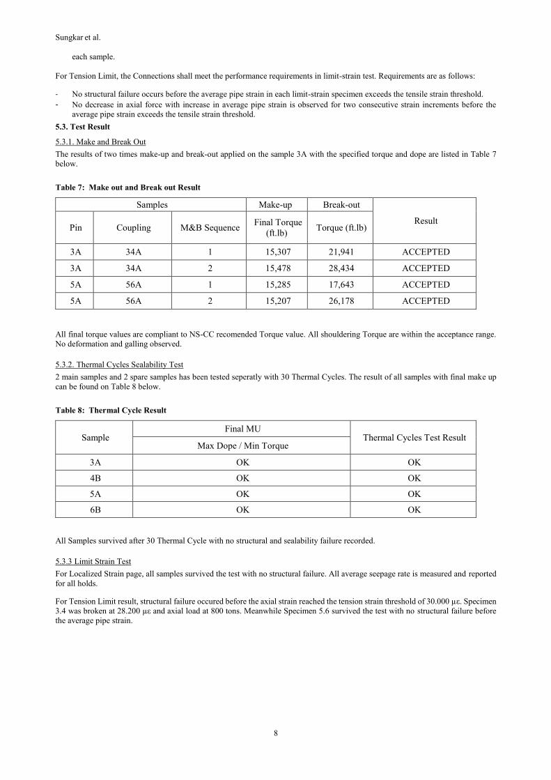
For Tension Limit, the Connections shall meet the performance requirements in limit-strain test. Requirements are as follows:
- No structural failure occurs before the average pipe strain in each limit-strain specimen exceeds the tensile strain threshold.
- No decrease in axial force with increase in average pipe strain is observed for two consecutive strain increments before the
average pipe strain exceeds the tensile strain threshold.
5.3. Test Result
5.3.1. Make and Break Out
The results of two times make-up and break-out applied on the sample 3A with the specified torque and dope are listed in Table 7
below.
Table 7: Make out and Break out Result
Samples Make-up Break-out
Result Pin Coupling M&B Sequence
Final Torque
(ft.lb) Torque (ft.lb)
3A 34A 1 15,307 21,941 ACCEPTED
3A 34A 2 15,478 28,434 ACCEPTED
5A 56A 1 15,285 17,643 ACCEPTED
5A 56A 2 15,207 26,178 ACCEPTED
All final torque values are compliant to NS-CC recomended Torque value. All shouldering Torque are within the acceptance range.
No deformation and galling observed.
5.3.2. Thermal Cycles Sealability Test
2 main samples and 2 spare samples has been tested seperatly with 30 Thermal Cycles. The result of all samples with final make up
can be found on Table 8 below.
Table 8: Thermal Cycle Result
Sample Final MU
Thermal Cycles Test Result Max Dope / Min Torque
3A OK OK
4B OK OK
5A OK OK
6B OK OK
All Samples survived after 30 Thermal Cycle with no structural and sealability failure recorded.
5.3.3 Limit Strain Test
For Localized Strain page, all samples survived the test with no structural failure. All average seepage rate is measured and reported
for all holds.
For Tension Limit result, structural failure occured before the axial strain reached the tension strain threshold of 30.000 µε. Specimen
3.4 was broken at 28.200 µε and axial load at 800 tons. Meanwhile Specimen 5.6 survived the test with no structural failure before
the average pipe strain.

Sungkar et al
9
Figure 5: Limit Strain Test for Specimen 5.6.
6. CONCLUSION
Selecting a proper production casing and casing connection for geothermal well is very crucial as the production casing and its
connection will experience various loads not only during drilling operations but also during its lifetime production operations.
In geothermal, the thermal load caused by temperature cycle during the production operations could potentially the highest load
experienced by the production casing and its connection that could lead to casing failure.
The NS-CC connection for 13-3/8” 68# L80 Type 1 production casing has passed the TWCCEP for geothermal application with
30 Thermal Cycle. Hence this connection is considered suitable for geothermal wells application.
7. RECOMMENDATION
It is recommended to use proper production casing connection for geothermal wells, especially those that has passed an applicable
thermal connection test. One of the applicable thermal connection test that can mimic geothermal condition is TWCCEP test protocol.
The NS-CC connection for the 13-3/8” 68# L80 Type 1 production casing, which has already passed the TWCCEP test, is one of
assured option for geothermal well in Indonesia and worldwide.
ACKNOEWLEDGEMENT
We would like to appreciate those who has conducted the entire testing work and who has support the preparation of this paper. The
authors would also like to acknowledge Firman Prasongko, Alvaro Rodriguez Martin, Sebastien Cochet, CDEC Batam, and Jakarta
Technical Team who gave a full support. Huge appreciation to all CDEC Batam member who has made everything happen from
preparation until finish. This is a monumental achievement for all of us as a team.
REFERENCES
American Petroleum Institut. Standards 5CT (2012). “Specification for Casing and Tubing”, 9th Edition.
International Organization for Standarization (2002). “Recommended Practice on Procedures for Testing Casing and Tubing
Connections”. ISO 13679:2002.
Noetic Engineering (2012). “Thermal Well Casing Connection Evaluation Protocol (TWCCEP)”. Public Domain Edition 1.3.
Riyanto, N., Napitupulu, G., and Wahyudin, S. S. (2017). “Connection Selection for Tie Back Production Casing in Geothermal
Wells”.
Teodoriu, C (WGC 2015). “Why and When Does Casing Fail in Geothermal Wells: a Surprising Question?”
Vallourec OCTG Division (2018), “Official Testing Procedures 13-3/8” 68# L80 NS-CC”. VRCC18-0224