a u requirements analysis & business process modeling prof. j. alberto espinosa business...
Post on 22-Dec-2015
218 views
TRANSCRIPT

AURequirements Analysis & Business Process Modeling
Prof. J. Alberto Espinosa
Business Analysis & Data Design ITEC-630 Fall 2009

22
Objectives Describe the requirements analysis process Introduction to business process analysis and modeling

33
RequirementsAnalysis

44
Why are accurate requirements so important?
The cost of fixing and error in requirements is:
Times larger If discovered during
5 Design
10 Implementation
20 Testing
100 Operations
Bohem, Barry R. 1981. Software engineering economics. Englewood Cliffs, N.J.: Prentice-Hall.
5
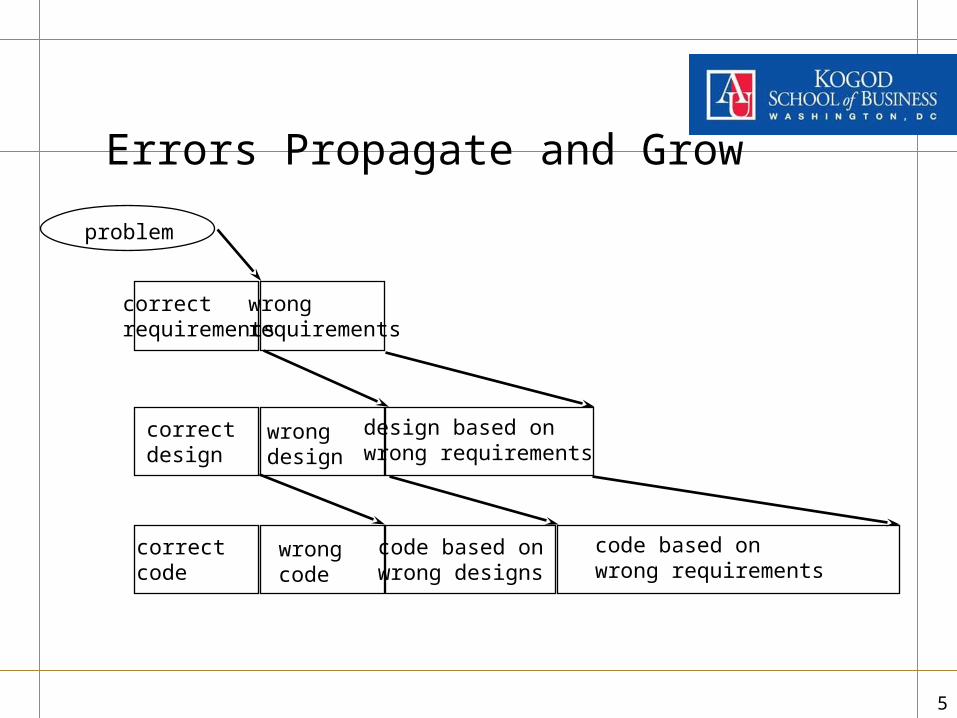
Errors Propagate and Grow
correctrequirements
wrongrequirements
correctdesign
design based onwrong requirements
wrongdesign
problem
code based onwrong designs
correctcode
wrongcode
code based onwrong requirements

66
Requirements Analysis isKey to Successful Development
Several studies have documented that requirements errors cost the most and that poor requirements are the main cause of software failure
GAO’92; Faulk’92; Bohem’81; Curtis’88
“The hardest single part of building a software system is deciding what to build. ...No other part of the work so cripples the resulting system if done wrong. No other part is more difficult to rectify later.”
Fred Brooks (1987) No Silver Bullet: Essence and Accidents of SW Engineering

77
Sources of Requirements
Users, Customers, other Stakeholders (e.g., employees, management, selected customers)
Standards (e.g., GAAP)
Policy/Legal (e.g. government regulations)
System Documentation (e.g. current system being replaced, could be manual)
Business Process Documentation (e.g. current business memos, manuals, practices)
Subject Matter Experts (e.g. experts on the business domain)
88
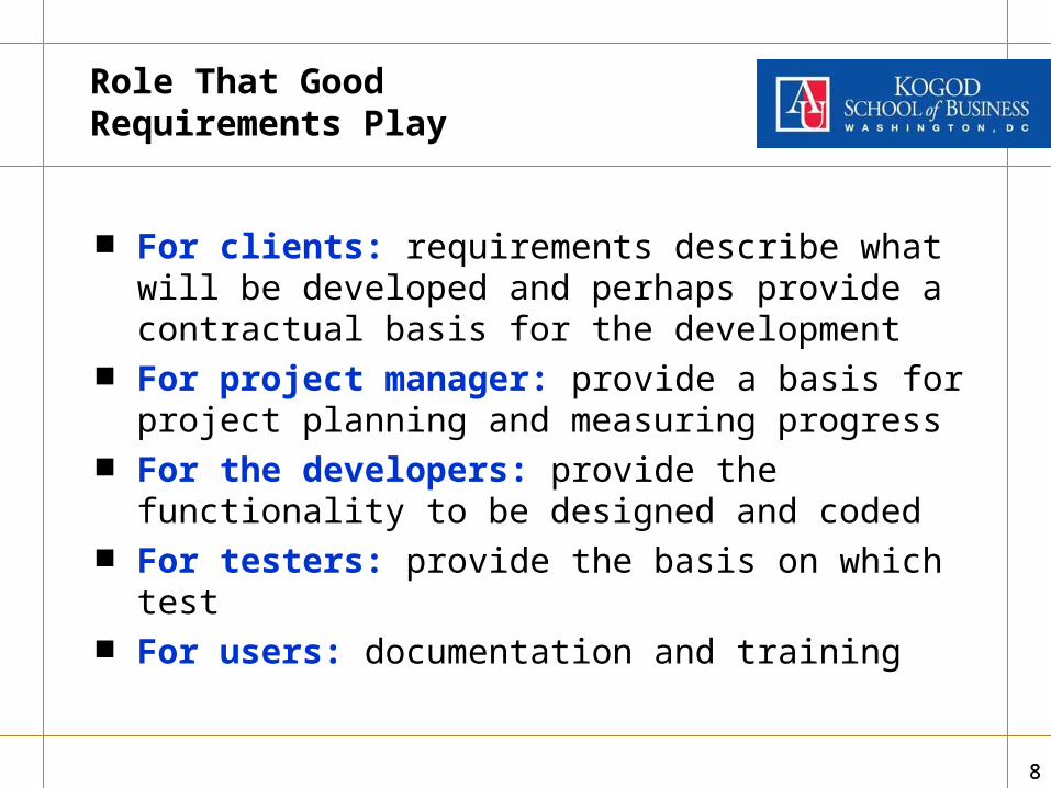
Role That Good Requirements Play
For clients: requirements describe what will be developed and perhaps provide a contractual basis for the development
For project manager: provide a basis for project planning and measuring progress
For the developers: provide the functionality to be designed and coded
For testers: provide the basis on which test For users: documentation and training

99
Capturing Requirementsis Difficult
Need to: Find out what is required by/from the system Understand these requirements and their implications Communicate (text and models) this understanding to
users, customers, designers and other stakeholders Manage them – i.e., record them in a traceable manner
and ensure that as requirements change, they are updated and the impact of the change is understood
Quality and fit – i.e., ensure that system meets the requirements

1010
Interviews
Interviews should be carefully planned Interview Process model
– Determine who to be interviewed– Prepare for, plan & schedule each interview– Open the interview:
introduction, purpose, permissions (to tape, etc.)– Conduct the interview:
semi-structured, open ended questions, mail questions in advance, let users digress, don’t agree or disagree on anything (just capture)
– Close the interview: summarize things, confirm facts– Follow up: resolve conflicts; close-ended questions

1111
Requirements Workshops
Approx 2 days before each UP iteration Multiple stakeholders participate:
multiple perspectives of the system It fosters clear communications between
Requirement Analysts, users and other stakeholders Fosters sense of participation and project ownership Helps accelerate requirements elicitation process Facilitators are often used Need a scribe to document the discussion Need rules for participation and problem resolution Need a process that fosters preparation Pre-specify expected deliverables Use artifacts that foster communication with the client:
A Business Process Model (or Map) is an excellent tool for this

1212
“Trawling” for Knowledge: Eliciting Requirements
“Running a net through the organization to catch every possible requirement source” (Robertson & Robertson)
With experience, you learn where to fish to find what you want Start with documents from the project “blastoff” meeting with
your client Elicit further requirements through: interviews, requirements
workshops, questionnaires, observations, job protocol analysis, prototyping, review of existing documents
Systematically “catch” and record all requirements Document anything that sounds like a requirement using an
organized form or template like: the Volere Requirement Shell

1313
Volere Requirement Shell

1414
Requirements Defined
In simple terms, requirements are things the product needs to do (i.e., useful functionality for its user) and the capabilities and qualities that it must have (i.e., non-functional)
IEEE definition:
1. A condition or capability needed by a user to solve a problem or achieve an objective
2. A condition or capability that must be met or possessed by a system or system component to satisfy a contract, standard, specification or other formally imposed documents
3. A documented representation of a condition or capability as in (1) or (2)

1515
Requirements Analysis
Find, understand, record and communicate:
• Functional Requirements (behavioral) What the system needs to do
• Non-functional Requirements (non-behavioral) The qualities of the system (e.g., speed, reliability, capacity)
• Other Requirements Project requirements, risk, costs, deliverables, deadlines, etc.
• Prepared using a “System Requirements Process”
• Articulated in a “System Requirements Specification”

16
Functional Requirements
• Are descriptions of “the work” the system needs to do• Articulated with text and/or models/diagrams• When you think of functional requirements think of verbs• The functional requirements define the “functional scope” of
the application – i.e., where its responsibility begins and ends• We will use “use case” analysis to define the functional scope
of applications in this course• Your articulation of functional requirements becomes your
“demonstrated understanding” of the business processes your system needs to automate – Eric Bristow, Deloitte Consulting
• Generally, functional requirements will take the largest share of time to gather – you must understand quite well what the system needs to do.

17
Non-Functional Requirements
• Are “the properties that your product must have … they are not part of the fundamental reason for the product’s existence, but are needed to make the product perform in the desired manner … they describe the experience that the user has while doing the work” – Robertson & Robertson
• Functional requirements – think of verbs• Non-functional requirements – think of adjectives• Non-functional requirements generally are better
known by clients and will not take as long to determine – but have huge implications on system cost.

18
Volere’s Non-Functional Requirements
10. Look and Feel Requirements – interface, style
11. Usability Requirements – ease of use/learning, personalization, access considerations
12. Performance Requirements – speed, latency, reliability, availability, capacity, scalability, etc.
13. Operational Requirements – technical/physical environment
14. Maintainability and Portability Requirements – ability to fix, support, and port the system
15. Security Requirements – access, integrity, privacy, etc.
16. Cultural and Political Requirements
17. Legal Requirements
19
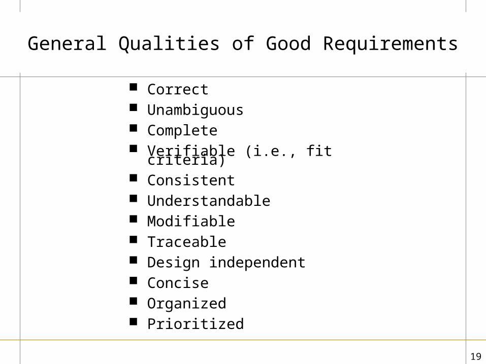
General Qualities of Good Requirements
Correct Unambiguous Complete Verifiable (i.e., fit criteria) Consistent Understandable Modifiable Traceable Design independent Concise Organized Prioritized
2020
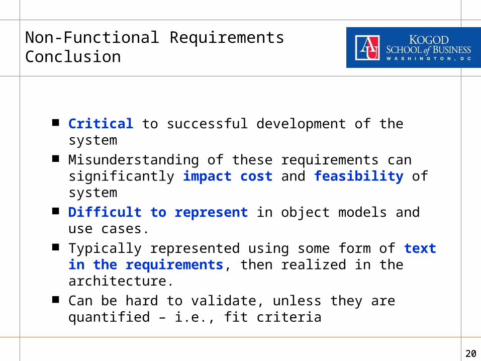
Non-Functional Requirements Conclusion
Critical to successful development of the system Misunderstanding of these requirements can
significantly impact cost and feasibility of system Difficult to represent in object models and use
cases. Typically represented using some form of text in
the requirements, then realized in the architecture. Can be hard to validate, unless they are quantified –
i.e., fit criteria

2121
Other Important Issues
Mandated constraints: are indistinguishable from design decisions, except that they are requirements mandated by the client – e.g. use Oracle platform for all databases; develop a web based application
Facts: are conditions about the system’s external environment (e.g., actors, systems, organizations) known to be true – they are different than mandated constraints in that they are about the application context, but not mandated by the client the system– e.g., visually and hearing impaired users will need to use
Assumptions: are conditions about the system’s external environment (e.g., actors, systems, organizations) believed, but not confirmed to be true – e.g., all users speak English

2222
Interviews
Interviews should be carefully planned Interview Process model
– Determine who to be interviewed– Prepare for, plan & schedule each interview– Open the interview:
introduction, purpose, permissions (to tape, etc.)– Conduct the interview:
semi-structured, open ended questions, mail questions in advance, let users digress, don’t agree or disagree on anything (just capture)
– Close the interview: summarize things, confirm facts– Follow up: resolve conflicts; close-ended questions

2323
Requirements Workshops
Approx 2 days before each UP iteration Multiple stakeholders participate:
multiple perspectives of the system It fosters clear communications between
Requirement Analysts, users and other stakeholders Fosters sense of participation and project ownership Helps accelerate requirements elicitation process Facilitators are often used Need a scribe to document the discussion Need rules for participation and problem resolution Need a process that fosters preparation Pre-specify expected deliverables Use artifacts that foster communication with the client:
A Business Process Model (or Map) is an excellent tool for this
2424
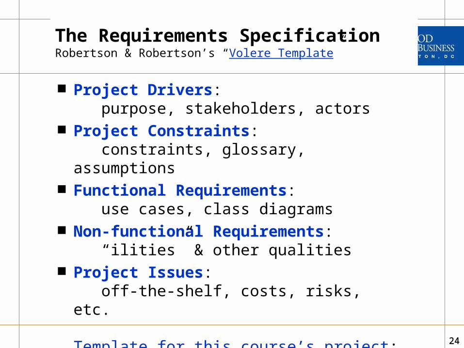
The Requirements SpecificationRobertson & Robertson’s “Volere Template”
Project Drivers: purpose, stakeholders, actors
Project Constraints: constraints, glossary, assumptions
Functional Requirements: use cases, class diagrams
Non-functional Requirements: “ilities” & other qualities
Project Issues: off-the-shelf, costs, risks, etc.
Template for this course’s project: an adaptation of the Volere Template

2525
Business Process Modeling

2626
Project Baselining Flow Chart
Initiation Phase Baseline Phase
Pro
ject
Dir
ecto
rB
usi
nes
s O
ffice
Pro
ject
M
ana
ger
(PM
)
Start
1New project
developed and approved
3Receives project information from
PM
8Enter Project Data
5Enters project data
into Finance Module
2Enter Priority Data
7Receives award information from
Acquisitions
9Prepares Project
Schedule and cost Baseline Report
10Is Prioritization
required?
No
Yes
4Back to PM
No
End
A (simplified) Deloitte BPM Example

2727
Business Process Model
The system you are gathering requirements for will automate one or more business processes
Therefore, it is very important that the requirements analysts and clients develop common ground on what these business processes are
The best way to achieve this is to develop a business process model and get the client to sign off on it
The idea is to develop a vision of “the work” that needs to be done, looking ONLY at the business aspects of the process
A business process model or map (BPM) fosters communication between the requirements team and the client; and within the team
It provides an excellent starting base to begin to articulate the system requirements

2828
BPM Symbols
Terminator: start and end points in a process – it only has one input or one output, not both.
Process step: a specific step in the process – it MUST have one input and one or more outputs
Pre-defined process: like a process steps but it actually incorporates multiple steps. They are useful to simplify the diagramming of complex processes
Decision: a question or a branching in the process flow it MUST have one input and one output for each possible decision outcome
Process flow: a directed arrow that specifies the process sequence
Functional bands or swim lanes: show which departments, units or functional roles are associated with different parts of the process
Phase or separators: use to differentiate different phases of the process
More BPM symbols:http://www.breezetree.com/article-excel-flowchart-shapes.htm

2929
Cross Functional FlowchartBPM Symbols
Process Name
Phase 1 Name Phase 2 Name
Sw
im L
ane
or
Fun
ctio
nal
Ban
d N
ame
Sw
im L
ane
or
Fun
ctio
nal
Ban
d N
ame
Sw
im L
ane
or
Fun
ctio
nal
Ban
d N
ame
Sw
im L
ane
or
Fun
ctio
nal
Ban
d N
ame
Process 1
Begining
EndDecision 1
Process 2 if Decision 1 is Yes
Process 2 if Decision 1 is No
Process Flow Yes
No
Annotations: use this symbol to embed comments
Database operation
Printed output
Page 2
Connect from/to another page

3030
Some Guidelines for Good BPM Modeling
Process steps: – Can have more than one input but only have one output – if you think you need
two outputs you probably need a decision symbol that evaluates which output path to follow
– Must have at least one input and one output – unconnected process step boxes without input and output are incorrect
Pre-Defined Process: – Same as process steps, but can have more than one output– In their detail diagrams, use connector symbols to show where the pre-defined
process connects to other sub-processes.
Decision (diamond): – Have one input and at least two possible outcomes– It may have more than two outcomes but this may point to more complex process
steps that are better described in a “pre-defined process”– All outcomes MUST be labeled (e.g., “yes”, “no”, “option 1
Process flows: – Must connect two symbols (process box, decision, start, end, etc.) – unconnected
flows are incorrect. You can add other symbols to add clarity (e.g., page references, connectors,
database, printout, etc.); label these symbols as needed for clarity

3131
Some BPM Guidelines
BPMs are used to document business processes, NOT systems actions – focus on understanding and documenting what people do and what the key processes are, rather than what the system solution will do.
In other words, you need to understand the business processes before you can suggest a solution.
It often helps to distinguish the baseline BPM (what the client does) from the target BPM (what the client wants or your proposed solution). You can add notations and other symbols to distinguish baseline from target processes
It may also help to distinguish processes that are carried out manually from those that are handled by applications
More importantly, this is NOT hard science – if you can do anything to add descriptive clarity to your BPM, by all means

3232
Some BPM Diagramming Rules
All BPM diagrams have one start and one end symbols.
If there are two or more distinct sub-processes, it is OK to break up the BPM into two sub-models, but each must have a start and end symbols.
If you have many sub-processes you can create one master BPM that includes “Pre-Defined Process” symbols and then create a separate BPMs for each of these pre-defined sub-processes.
You can include many symbols in the diagram to add clarity to your process descriptions. Some symbols just add clarity (e.g., comment, database store, printout), whereas others have very specific rules on how to use them.
More BPM guidelines: http://www.edrawsoft.com/flowchart-symbols.php

3333
BPM Example - CurrentCross-Functional Flowchart

3434
More Guidelines(see vehicle prior rental example)
If there is a process already in place (i.e., baseline) and you are proposing process improvements (i.e., target)
Differentiate the two in your diagram or have two separate diagrams
If your solution includes building a system but there are process steps that will not be handled by the system, your diagram(s) should distinguish the manual steps from those to be handled by the system
It is important to number or label all the process steps (P1, P2, etc.) and the decision steps (D1, D2, etc.) to:
– Facilitate reference to specific parts of the process
– To cross reference with other models using “transitional artifacts” (more on this later)

35
BPM Example – Proposed
35

3636
Some BPM Diagramming Guidelines for Complex BPMs
If the BPM is complex and there are two or more distinct sub-processes, it is recommended to break up the BPM into two sub-models, and then:– Prepare a high level or master diagram that shows
all the sub-processes using pre-defined process symbols
– Prepare a separate detail diagram for each sub-process

3737
Master BPM ExampleEach Pre-Defined Sub-Process Box Has its Own BPM Diagram
Master Business Process Model
Start Phase 1 Phase 2 End
Bus
ines
s P
roce
ss 3
Bus
ines
s P
roce
ss 3
Bus
ines
s P
roce
ss 2
Bus
ines
s P
roce
ss 2
Bus
ines
s P
roce
ss 1
Bus
ines
s P
roce
ss 1
Begin
End
Decision A
Decision B
Option A
Option B
No More
Please Proceed
Sub-Process 1.1
P.2
Sub-Process 2.1
P.3
Sub-Process 3.2
P.4
Sub-ProcessStep A
Sub-ProcessStep B
“Pre-Defined Process” symbol used for more complex process steps with a page connector. In this case P.3 should have a
separate BPM showing all the steps of this pre-defined process
Regular process step symbol used for simpler steps
Page symbol to help navigate to the sub-process BPM
Which sub-process?

3838
BPM Example – Proposed
Paperwork
Vehicle Prep
Vehicle Delivery

3939
BPM Example – High Level Diagram

40
BPM Example:Defined
Process DetailsConnector