a uniï¬ed architecture for sensor networks with multiple
TRANSCRIPT
A Unified Architecture for Sensor Networks withMultiple Owners
Pradeepkumar Mani, Satyasree Muralidharan, Victor Frost†, Gary Minden, David PetrInformation and Telecommunication Technology Center, University of Kansas, Lawrence, KS 66045
Email: {mpradeep, satyam, frost, gminden, dwp}@ittc.ku.edu
Abstract— In practical sensor networks, it is possible that vari-ous components of the sensor network are owned and maintainedby different organizations. This complicated scenario rendersprovision of security and management of these components as achallenging task. A framework for assured and controlled accessfor sensor networks is needed. In this paper, we describe suchan architecture which integrates various component technologiesinto a unified framework. We also describe details of a proof-of-concept implementation, an IEEE 1451 - based multi-hop wirelesssensor network application that demonstrates the salient featuresof our unified multi-ownership architecture
I. INTRODUCTION
SENSOR networks have been identified as being key tech-nology in monitoring and detecting threats. These systems
face critical technical challenges in providing a security andmanagement architecture in scenarios representative of a largeclass of applications. Although the design and architecture ofsensor networks [1], [2] and [3] have been studied and manynetworks have already been deployed [4], the development of aunified architecture for these systems when network elementsare owned by disparate organizations is yet to be created.The architecture that we have developed addresses theseissues by incorporating well-defined interfaces between differ-ent components with appropriate authorization/authenticationmechanisms that are secure and suited for disseminating andanalyzing sensor information.
As a motivating example, consider the following scenario:several times a year about 125,000 people, along with theirthousands of cars and RVs, attend a NASCAR race eventat the Kansas Speedway in Wyandotte County, Kansas. Onevent days the Speedway becomes the third largest city inthe State. The Kansas Speedway is a private entity thatuses several subcontractors to provide services, e.g., on-sitewireless internet access and cell phone services. The event alsodraws in law enforcement and other personnel from severalagencies including the State of Kansas and Wyandotte County.Clearly, safety and security are major concerns for such events.There is a need to develop and deploy technologies that areaffordable yet effective and also enhance “normal” safety andsecurity operations.
Simply placing sensors and cameras at the venue does notsatisfy these requirements. Sensors must be integrated into an
†corresponding authorThis work was partially supported by Oak Ridge National Labs underAward Number 4000043403, as part of the ORNL-SensorNet Initiative
overall architecture to provide the responsible authorities bothon- and off-site with situation awareness. Situation awarenessincludes: the location of personnel and assets (e.g., venue staffand health professionals), the state of the venue, and pastexperiences. A command center facility staffed from multipleagencies needs to be able to direct the collection of informationto meet their immediate needs, translating the informationinto knowledge to be used as the basis of decisions on howbest to maintain the safety of the venue. Information wouldflow to the headquarters facility from sensors, cameras, voicecommunications, and data archives, where each of these maybe owned by separate entities. Situation awareness applicationswould facilitate transforming this information into knowledge.The decision-makers would then use this knowledge to directthe allocation of resources, e.g., point cameras or repositionpersonnel. The unique requirements of this scenario include 1)a rapidly deployable system and 2) consideration of multipleowners of data and infrastructure.
The remainder of this paper is organized as follows: Weidentify some key challenges in the development of a unifiedarchitecture for sensor networks with multiple owners insection II. In section III, we discuss research pertaining toour work in the existing literature. We discuss our proposedarchitecture in section IV, and in section V, we describe brieflythe Ambient Computational Environment (ACE) [5] [6] archi-tecture and its extensions that form the heart of our unifiedmulti-ownership architecture. In section VI, we describe indetail the prototype sensor network that we implemented todemonstrate proof-of-concept of our unified architecture; wealso include some lessons learned in the process. Finally, insection VII, we present the conclusions of our work.
II. CHALLENGES IN A MULTI-OWNER SCENARIO
The development of a unified architecture for sensor net-works with multiple owners has not yet been fully exploredand validated. Design, development, construction, deployment,and evaluation of a sensor network to enhance the safety andsecurity for venues like the Kansas Speedway pose significantresearch and technical challenges including the followingquestions:
1) What kind of access/control/security mechanisms needto be developed to facilitate the participation of multipleorganizations? These mechanisms must allow for differ-ent policies for observing and/or controlling sensors.

2) What software systems and hardware are required toassist in the rapid and easy deployment, management,use, and redeployment of sensor networks?
3) How can device reconfiguration be minimized?4) What is a suitable naming/addressing scheme given that
the devices will be moved from venue-to-venue? Shouldthe naming be context-aware?
5) To make the system affordable, how can commercial-off-the-shelf (COTS) wireless technologies be leveragedfor use in an environment characterized by the heavyuse of wireless communications equipment?
6) How can “high bandwidth” applications like video besupported?
From our experience with the prototype implementation ofour proposed architecture, we are able to provide answers toseveral of these questions.
III. RELATED WORK
There is growing literature concerning the architecture anddesign of sensor networks [1], [2], [3], as well as the OpenGeospatial Consortium Sensor Web Enablement efforts [7] andOak Ridge National Lab’s SensorNet Information Architecture[8]. Several sensor networks have already been deployed [4].Given all this prior activity, what are the barriers to deployingsuch a system for venues like the Kansas Speedway? Clearly,many of the component technologies required to realize theabove scenario exist: sensors (especially chemical and radio-logical), cameras, communications systems and networks, dataarchives, GPS (or other location identification methods), GISsystems, and situation awareness applications. It would be astraightforward engineering task to design a “one-off” deploy-ment, owned and controlled by one organization that maysatisfy the needs of one venue. However, this is not practical,and we lack the knowledge concerning the deployment issuesassociated with a suitable integrated system architecture thatcould be reused across many venues.
A premise of this research is that elements of the system willbe owned by multiple organizations and communicate acrossadministrative domains. Thus, there is a need for mechanismsthat facilitate access to and control of sensors across multipleorganizations as well as a requirement for rapid deployment.Ownership by a wide variety of administrative domains isbriefly mentioned in [9]. Also, while SensorML [10] has sen-sor schemas that include security, user limitations and accessconstraints (like documentConstrainedBy), and schemas thatidentify the responsible party (like operatedBy), the integrationof these into an overall system remains to be explored.
Our proposed architecture is consistent with ORNL’s Sen-sorNet Information Architecture and has been built upon theexisting sensor network architectures (e.g., [7], [11], [9], and[12]), to create a system based on the above concepts thatfacilitate the participation of multiple organizations in supply-ing needed component/subsystem functionality. A model ofthe new system has been implemented and evaluated.
IV. PROPOSED ARCHITECTURE
The objective here is to develop a unified architecture thathas elements owned/controlled by a variety of organizationswhich can communicate across across administrative domains.Our proposed architecture is general (not a point solution),scalable (in size and evolution of technologies), flexible(able to mix and match technologies based on the venuerequirements), economical (based on COTS technologies), andleverages standards where possible. The proposed approachfacilitates multiple organizations providing different services,enabling the development of a business model based on sensornetwork technologies. A rapidly deployable and transportablenext-generation, secure, digital, wireless sensor web for largecrowd events as proposed here has some unique features ascompared to previous applications of sensor network technol-ogy. The key features of the proposed architecture include:
• Assured and controlled access to sensor nodes in a multi-owner environment.
• Archiving and information dissemination.• Application supporting high bandwidth requirements.• Rapidly deployable sensor networkThe architectural components are divided into three layers
as shown in the Fig.1 based on their functionality:1) Device Layer2) Repository Layer3) Application Layer
A. Device Layer
Device Layer composes of all the physical sensor endpointstogether with the first level of data access and managementpoints for the entire architecture. This consists of:
• Sensors• Sensor nodes• Sensor services• CollectorsA Sensor is a device that responds to an environmental
quantity (e.g. light, temperature, etc.) by generating a function-ally related output usually in the form of an electrical or opticalsignal. Sensors communicate the collected data to the nodethat controls them in the sensor network. The sensors could beof different types such as radiological, mechanical, optical orchemical sensors. Often sensors are characterized by small sizeand low energy consumption. Sensors can be broadly classifiedinto two types: active sensors, and passive sensors. Active sen-sors usually engage in two-way communication with the datacollecting host. They can accept commands from the sensornode in real time, and send appropriate responses back. Passivesensors, on the other hand, simply send back (periodic/event-driven) data to the collecting node. They usually do not supporta Request- Reply type of communication with the control node.
A sensor node is a computer that typically manages one ormore sensors through a set of services. The sensors could bedirectly connected to the sensor node either through serial orparallel ports or through a multi-hop network. The commu-nication between the sensors and the node may or may not

Fig. 1. Proposed Unified Multi-Ownership Sensor Network Architecture
incorporate a secure communication. The security of this linkdepends upon the nature of the connectivity. If the sensors areplugged to the node directly through serial or parallel ports,then the communication is inherently secure. With a multi-hopwireless network, security should be explicitly incorporated inthe communication links.
Sensor services are programs that control the sensors at-tached to the node. There could be one or more servicesper node, with each service dealing with one sensor. In thisproposed architecture, there is a one-one mapping betweenthe sensor service and the sensor controlled by it. In practicalapplication, a single service could control more than onesensor. The architecture proposed here could be extended sothat one service supports multiple sensors.
Collectors are programs that collect data from these servicesand transport them to the repository layer for further use.There could be one or more collectors depending on thesize of the device layer. The communication between thecollectors and the sensor services follow the access controlmechanism discussed later in this document. Collectors shouldauthenticate and authorize themselves with the service, beforetasking or configuring a sensor. Collectors gather data inone direction (from device to repository); other services loaddata or commands from repository to device, e.g., the SensorDatabases to the sensors to command the sensors. Collectorstalk to the devices which typically belong to their organizationor domain; our solution is not restricted for such a communi-cation but spans across different organizational domains.

B. Repository Layer
This forms a link between the lower device and the upperapplication layer allowing dissemination of information. Thisconsists essentially of databases of two types:
• Sensor Databases that store and retrieve sensor data,e.g., database of images captured by cameras used forsurveillance.
• Infrastructural databases that store other information re-quired to support the system, e.g.,
– Service Directory - database of current services avail-able such as Temperature Sensing Service, ChemicalSensing Service.
– Regional Database - database of location of sensors.There could be multiple repositories in this layer, each
owned by a different organization. The services from thedevice layer register themselves with the Service Directorywhen they come online, necessitating each organization tomaintain a list of currently available services.
C. Application Layer
The application layer provides a unified view of the variouscomponents of the architecture to the user. A user in thisarchitecture is a human being who uses the infrastructurefor various applications. Applications are programs that canbe either talk to the organizer to get the processed data ortalk to the services directly. An organizer is a program thatfetches data from the repository layer and presents mean-ingful interpretations to the requesting application. Considerthe NASCAR scenario described in section I. The securitysystem at the NASCAR venue could have temperature sensorsdeployed to monitor various threats such as fire, etc. Anagent program collects raw temperature data, converts theminto location-centric values, and writes them into the databaseof temperature values. The system could also have camerasdeployed at various locations in the venue to provide on-demand, live video feed. The temperature sensors, camerasand the database could be owned by different organizations.A security officer has a monitoring application program thatshows the location of the various temperature sensors, andthe temperature values recorded by them (retrieved fromthe database). The monitoring application raises an alarmwhenever any sensor shows a temperature value that is outsidea specified range. The security officer uses the monitoringapplication to request video feed for the location of thesuspected fire. Based on the contents of the video feed, theoffice can then initiate appropriate actions.
The architecture described here could be applied directly tothis scenario. Referring to the architecture, the agent programin this example plays the role of the collector and organizer-it transports sensor data (temperature, video) from the devicelayer to the repository later, and from the repository layer tothe application layer (monitoring application program used bythe inspector). The owner of each of these components (sensor,camera, database, etc.) is an organization and the securityofficer is the user.
This 3-tier architecture is layered with organized commu-nication between the layers using the intermediaries such ascollectors and organizers. However, we anticipate that somescenarios might require a user talking directly to a devicewithout having to pass through this layered architecture.
Consider a situation where the user takes direct control overthe sensors of all organizations and may wish to control themwithout having to talk to the organizer or the collector. In sucha case, the user will get a single certificate to talk to devicesfrom all organizations. The user will use the applications totalk to the sensor services controlling the devices throughan out-of-band communication. Our solution also providesa way to have this Direct Communication between the userand the devices as in Fig.1. With reference to the NASCARsecurity system described above, the video feed from thecamera requires direct communication between the user andthe camera.
The description of the unified architecture is not yet com-plete. We still have not discussed the following issues:
1) Inter-layer communication2) Policies for the following:
a) Secure, controlled and authorized access to a spe-cific component (sensor, database, etc) in a multi-owner heterogeneous sensor network. These poli-cies will be important if we would like to restrictaccess to only a specific instance of the component,in the presence of multiple similar components(e.g. temperature sensor # 43)
b) Secure, controlled and authorized access to a spe-cific functionality of a specific component in amulti-owner heterogeneous sensor network. Thesepolicies are required if we would like the clientto have access to only a subset of functionali-ties offered by a specific component. (e.g. onlyREAD function from Temperature Database, butno WRITE privileges)
3) Propagation and enforcement of the policiesWe address all the above-mentioned issues by extend-
ing the ACE [5], [6] architecture. The device control anddata flow mechanisms developed for ACE are used here tomanage/control connections between applications and sensornodes. The ACE control mechanisms provide for authentica-tion by the device of the controlling application, authorizationto access and control the device based on an established secu-rity policy, confidential transmission, and integrity checks. TheACE data flow mechanism supports real time exchange of databetween applications and devices that is private and checkedfor integrity. ACE supports establishing services within theenvironment to archive data flows, replicate data flows tomultiple receivers, and play back archived data. The nextsection briefly discusses the ACE architecture
V. THE ACE ARCHITECTURE
ACE provides a secure communication fabric between thevarious components in the various layers of the unified ar-chitecture. The ACE architecture was developed to be the

Fig. 2. ACE Architecture showing the various components and theircommunications
basis for a pervasive system, where the users have long-livedworkspaces and mobility within the environments irrespectiveof rooms or machines. In other words, in the ACE system, theusers can roam anywhere, while still preserving their sessionswith the resources.
ACE supports two types of communication channels be-tween the client and the service:
1) Control channel: Provides a way for communicatingcontrol messages. It is a reliable in-order channel.
2) Media channel : Provides a way for communicatingaudio and video. Reliability and in-order delivery arenot important in this channel.
In the ACE architecture, services constitute the atomiclevel of computation. The most important services are thethree core services - Service Directory service, User Databaseservice, and Regional Database service. These core servicesare programs that inter-operate as shown in the Fig.2, per-forming user authentication and verifying user authorizationto allow a client to only access resources that he is permittedto. The Service Directory is a directory service that locatesall available services as well as their characteristics (Name,Location, and Service Class). All services register and un-register with this service. Since this is the directory for allthe other services, the location of this service is fixed. TheUser Database is a database of all users in the system.The information includes Public Key, Name, Login nameand Login characteristics. In ACE, the login characteristicsinclude information like passwords, finger prints and iButtonidentifiers that can identify the user. The Regional Database isa database of the information of all the service locations in thesystem (e.g. rooms containing various sensors, geographicalco-ordinates of administrative boundaries of the NASCAR racetrack and associated sensors, etc.).
A. Key Features of ACE for the Architecture for SensorNetworks
We have already mentioned that the architecture for sensornetworks demands secure communication between the various
components of the system (client, services, etc.), component-level access control to each and every component in thenetwork, and method or function-level access control to everyfunctionality of a given component. We briefly discuss thefeatures of ACE that are suitable to the requirements of thisarchitecture.
1) Client Server communication using Enhanced RMI:Whenever a client wants to talk to the Service, the clientprovides his credential showing that he has permissionsto talk to the service to access the resources. The servicevalidates his credential before providing the resource.The authorization not only provides access to the re-source, but also extends to every method that the clientrequests to perform on the device.The services present themselves as Java remote objects.The functionalities that the services advertise are givenin the Java Interface. The client obtains the remoteobject to the service and performs actions using theJava RMI. This feature can be directly applied to thetarget architecture with the collectors being the clients,sensors being the devices, and the sensor service beingthe gateway between the collectors and the sensors.
2) Secure communication using TLS:Transport Layer Security (TLS) provides authenticationof the user and security of the message exchanges in thecontrol channel. The users are identified by public keyof the asymmetric key (either RSA or DSA). The publickey is certified by a Certificate Authority to verify thevalidity of the key. A Certificate Authority (CA) is anentity that issues digital certificates. Each organizationwill have its own CA to issue certificates for users withinthat organization. The role of the CA is to issue 1)certificates to identify the users and, 2) credentials toidentify the actions that can be performed by the users.If a user wants to talk to devices from multiple or-ganizations, then he/she needs to contact the CAs ofdifferent organizations individually to get certificates.The user presents this signed certificate to any servicefor authentication. At the end of the handshake betweenthe client and the server, a session key is negotiated andall the messages are encrypted with this key using anysymmetric key algorithm such as AES or DES. In thisarchitecture, security of the message exchanges betweenthe collectors and the sensor services is important.This TLS and AES encryption of the ACE frameworkprovides authentication of client-server, secured com-munication by encrypting the message exchanges andprovides error-free delivery as required here.
3) Access Control using KeyNote Trust Management Sys-tem:Once user authentication is complete, the service pro-grams determine the actions that the user can performbased on the exact permissions assigned to the user -i.e., the service must authorize the actions requested bythe user based on these permissions. ACE uses KeyNote

Trust Management [13] to provide access control onthe actions requested by the users. KeyNote providesa simple language for describing and implementingsecurity policies, trust relationships and digitally-signedcredentials to control potentially dangerous actions overuntrusted networks. The policies are specified using theKeyNote language, which is then signed by the CA, andgiven to the client as a credential file. The user presentsthis credential file to any service that he wishes to access.This trust management allows the system to controlaccess to the actions performed by a collector on thesensors. Each method that the client is trying to accessthrough the remote object of the service can be checkedfor authorization by querying the KeyNote engine. Ifthe collector does not have a valid credential, it cannotperform the requested action on the sensor and an ex-ception is raised. Since this authorization is implementedwithin the service infrastructure, all services inherentlyimplement the authorization procedure. Detailed de-scriptions of the KeyNote trust management system andthe KeyNote description language are beyond the scopeof this paper. Interested readers are referred to [13] and[14] respectively.
B. Access Protocol in ACE
In our architecture, the ACE framework provides the re-quired client-server authentication, secure communication (byencrypting the message exchanges), and error-free delivery.The ACE architecture contains the KeyNote mechanism,which enables formulation and enforcement of policies.
The user presents the signed certificate from the CA to anyservice for authentication. The sequence of actions when anACE user talks to an ACE Service is described below. Eachtime a new client contacts a service, the service spawns anew thread dedicated to the communication with the specificclient. Typically the following happens when a client wishesto access a resource, as shown in Fig.3:
1) User contacts the service (the client thread of the ser-vice) for establishing a session.
2) The service replies with its certificate for authentication,key exchange for establishing session key and requeststhe user for his certificate.
3) The user replies with his certificate and session keyexchange. The user verifies the Server’s certificate. Theclient sends Finished.
4) The service contacts the user database to verify theuser’s certificate. Once verified, the service sends Fin-ished. The TLS authentication is completed and a ses-sion is established.
5) The service creates a new KeyNote Session that will beused for user’s authorization.
6) The service provides the required policy to KeyNotedatabase to be used to verify the client’s credentials later.
7) The client provides his credential to the service.8) The service adds this credential to the KeyNote database.
Fig. 3. Access Protocol showing the sequence of actions when an ACEClient contacts the Service Directory
9) The service replies the result of adding the credentialsto the user.
10) The client requests the service to list the availableservices.
11) The service provides the KeyNote, the current set ofaction attributes such as domain in which this applicationis used, room in which the service runs, current Timeand the method requested by the client.
12) The Service queries the KeyNote for authorizing theaction requested by the client.
13) The KeyNote engine verifies the credential against itscurrent set of attributes and returns the result to theService.
14) The Service determines whether to perform the actionrequested by the client or not depending on the resultfrom the KeyNote engine. If the Service performs theaction, it returns the result to the client. Else, it returnsan Access Denied exception to the client.
VI. DEMONSTRATION OF MULTI-OWNER UNIFIEDARCHITECTURE
We wanted to choose a simple, yet powerful applicationto demonstrate the salient features of our multi-owner unifiedsensornet architecture, namely secure access and control of thevarious entities in a heterogeneous network of sensors. To thisend, we focused on a “chemical detection” sensing application.Initially, a database was populated with profiles of the variouschemicals of interest. An authorized client can retrieve theprofile corresponding to a specific chemical, and load it intothe detection sensor. Another authorized client (or perhaps thesame client as the initial one) can issue commands enablingthe sensor to detect the presence of a chemical. Note that the

database (and perhaps the individual profiles themselves), andthe sensor need not be owned by the same organization.
To build this system, we had to choose a number ofcomponents. First, we had to decide on the specific sensor wewere going to use. Based on the requirements of the sensor(bandwidth, processing power, etc), we then had to choosea wireless sensor network technology to build the network.For future extensibility with minimal system reconfiguration,we chose a standard sensor interface. All the hardware andsoftware components associated with the sensor, the wirelessnetwork and the software library that provides the standard-ized interface belonged to the Device Layer. To support thisarchitecture, we needed databases for the core services. Wealso needed databases that stored the sensor-related data (e.g.chemical profiles, video, etc.). These databases formed part ofthe Repository layer. Finally, we needed application programsthat allowed a client to interact with the components in thesystem. This software was part of the application layer. Below,we briefly describe our choices for the various components,and some issues that we faced with our choices.
A. Choice of Sensor
To realize the application, the first task at hand was tochoose a sensor that was easy to operate and program, whileat the same time had a sufficiently rich set of features thatwould allow us to demonstrate secure control and access undera variety of multiple ownership scenarios. It is apparent thatwe would require an active sensor for the application underconsideration. We chose the Cyranose 320 Electronic Nosesensor [15] (referred to simply as Nose henceforth), whichmet all of our requirements. The Nose is a handheld sensingdevice that can be trained to identify the presence of certainchemical compounds or substances.
1) Using the Nose: The training procedure is a rigorousprocess, and has to be conducted in controlled environments.The training procedure consists of a series of controlledexposures of the Nose to the target substance. Each exposureresults in a smell print, and the result of the training procedureresults is a series of smell prints, collectively called as asmell profile (corresponding to the target substance). The Nosestores the smell profile in its internal memory. This smell-profile can be retrieved from the Nose, stored externally inthe form of a file, and can be loaded into the Nose at afuture date. The identification procedure requires the Noseto be exposed to unknown substance for a brief period oftime. The Nose compares the smell-print that is created dueto this exposure against the smell profile (series of smell prints)already stored in the Nose. The result is a percentage matchbetween the unknown substance and the known substance (thesubstance corresponding to the smell profile loaded into theNose). During the training process, we realized the following:
• The accuracy of the smelling process depended heavilyon the accuracy of the training process.
• The Nose is not a suitable device for real-time scenarios(such as smoke detection, etc.) due to the time to generate
results. It is targeted as a hand-held device that requiresoperation in a controlled environment.
Despite these disadvantages, the Nose was still the preferredsensor to demonstrate proof-of-concept of the architecture dueto its simplicity of operation and rich set of control features.For our experiments, we trained the Nose to distinguishbetween Isopropyl Alcohol and Water. The following subsetof commands were the focus of the demonstration:
1) LOAD PROFILE - loads the provided smell profile fromthe file provided
2) START IDENTIFICATION - starts to “smell” the sam-ple provided to match it to one of the possible candidatesin the smell profile
3) FETCH RESULTS - returns the result of the latestidentification along with a confidence measure
B. Choice of Standardized Sensor Interface
To support a heterogeneous mix of sensors, a standardizedinterface was necessary to communicate with the sensors.Such standards ensure that a standardized software interfacewill be exposed by the architecture to the sensors/devices inthe system. These interfaces minimize developmental effortsrequired when new sensors need to be integrated into thesystem in the future.
The IEEE 1451 standard [16] is one such standard that hasbeen developed precisely for this purpose. Also the ORNLSensorNet architecture [8] has selected the IEEE 1451 stan-dard for this effort and its services. The IEEE 1451 standardwas also chosen as an example for the prototype architecture- the system designers could use any competing standard suchas Microsoft’s Universal Plug and Play (UPnP) [17], or OpticalSensor Interface Standards [18] in case of optical sensors.We do not make any recommendations on the choice of thestandard. For more details on the IEEE 1451 standard, readersare referred to [16].
A key challenge in this task was to efficiently integrate thedeveloped framework and IEEE 1451, so that standardizedinterfaces are exposed to the sensors by the Nose Server. AnIEEE 1451-compliant server is also called a Network CapableApplication Processor (NCAP) [19]. We chose the Java Dis-tributed Data Acquisition and Control (JDDAC) library [20]to build our custom Nose NCAP. Though the JDDAC was not100% compliant with IEEE 1451, it was deemed sufficient dueto lack of alternative IEEE 1451 software in Java (Java waspreferred because the bulk of the ACE code was written inJava), and also to demonstrate proof-of-concept.
One of the main obstacles in using the Nose as a sensingdevice in a IEEE 1451 environment was that the Nose was notan IEEE 1451 - compliant device. We overcame this obstacleby placing a Nose-1451 interface in the NCAP [19] module,that did the following:
1) convert incoming IEEE 1451 compliant messages fromthe client to Nose-Specific commands and send it to theNose, and
2) convert incoming Nose-specific message from the Noseinto a IEEE 1451 message, and send it to the client
In addition, the JDDAC library did not support a Request-Reply type of communication, which is critical in future sensornetworks, and thus to our application. We overcame this byextending the JDDAC IEEE 1451 library by implementingthe necessary features from the IEEE 1451.0 [19] standardsdocument to support a Request-Reply type of communication.
C. Choice of Sensor Network
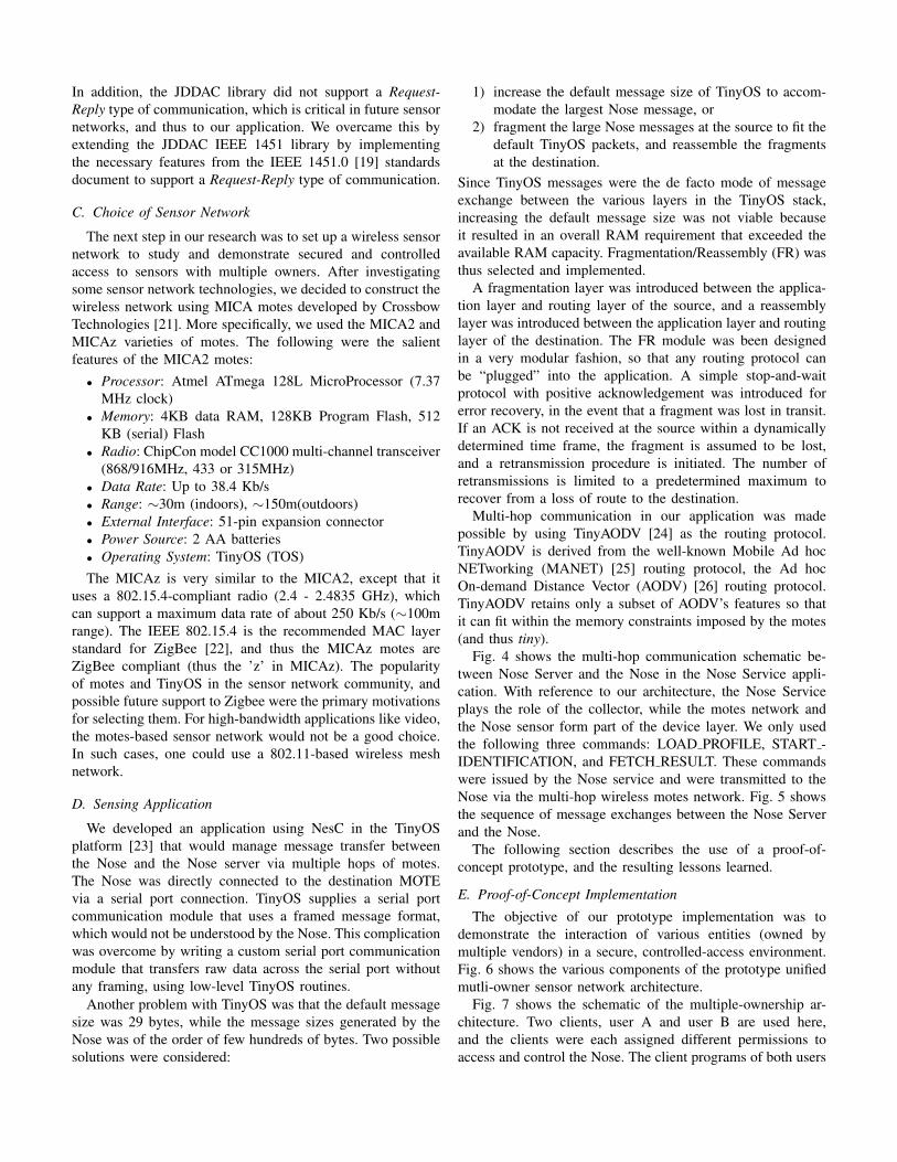
The next step in our research was to set up a wireless sensornetwork to study and demonstrate secured and controlledaccess to sensors with multiple owners. After investigatingsome sensor network technologies, we decided to construct thewireless network using MICA motes developed by CrossbowTechnologies [21]. More specifically, we used the MICA2 andMICAz varieties of motes. The following were the salientfeatures of the MICA2 motes:
• Processor: Atmel ATmega 128L MicroProcessor (7.37MHz clock)
• Memory: 4KB data RAM, 128KB Program Flash, 512KB (serial) Flash
• Radio: ChipCon model CC1000 multi-channel transceiver(868/916MHz, 433 or 315MHz)
• Data Rate: Up to 38.4 Kb/s• Range: ∼30m (indoors), ∼150m(outdoors)• External Interface: 51-pin expansion connector• Power Source: 2 AA batteries• Operating System: TinyOS (TOS)The MICAz is very similar to the MICA2, except that it
uses a 802.15.4-compliant radio (2.4 - 2.4835 GHz), whichcan support a maximum data rate of about 250 Kb/s (∼100mrange). The IEEE 802.15.4 is the recommended MAC layerstandard for ZigBee [22], and thus the MICAz motes areZigBee compliant (thus the ’z’ in MICAz). The popularityof motes and TinyOS in the sensor network community, andpossible future support to Zigbee were the primary motivationsfor selecting them. For high-bandwidth applications like video,the motes-based sensor network would not be a good choice.In such cases, one could use a 802.11-based wireless meshnetwork.
D. Sensing Application
We developed an application using NesC in the TinyOSplatform [23] that would manage message transfer betweenthe Nose and the Nose server via multiple hops of motes.The Nose was directly connected to the destination MOTEvia a serial port connection. TinyOS supplies a serial portcommunication module that uses a framed message format,which would not be understood by the Nose. This complicationwas overcome by writing a custom serial port communicationmodule that transfers raw data across the serial port withoutany framing, using low-level TinyOS routines.
Another problem with TinyOS was that the default messagesize was 29 bytes, while the message sizes generated by theNose was of the order of few hundreds of bytes. Two possiblesolutions were considered:
1) increase the default message size of TinyOS to accom-modate the largest Nose message, or
2) fragment the large Nose messages at the source to fit thedefault TinyOS packets, and reassemble the fragmentsat the destination.
Since TinyOS messages were the de facto mode of messageexchange between the various layers in the TinyOS stack,increasing the default message size was not viable becauseit resulted in an overall RAM requirement that exceeded theavailable RAM capacity. Fragmentation/Reassembly (FR) wasthus selected and implemented.
A fragmentation layer was introduced between the applica-tion layer and routing layer of the source, and a reassemblylayer was introduced between the application layer and routinglayer of the destination. The FR module was been designedin a very modular fashion, so that any routing protocol canbe “plugged” into the application. A simple stop-and-waitprotocol with positive acknowledgement was introduced forerror recovery, in the event that a fragment was lost in transit.If an ACK is not received at the source within a dynamicallydetermined time frame, the fragment is assumed to be lost,and a retransmission procedure is initiated. The number ofretransmissions is limited to a predetermined maximum torecover from a loss of route to the destination.
Multi-hop communication in our application was madepossible by using TinyAODV [24] as the routing protocol.TinyAODV is derived from the well-known Mobile Ad hocNETworking (MANET) [25] routing protocol, the Ad hocOn-demand Distance Vector (AODV) [26] routing protocol.TinyAODV retains only a subset of AODV’s features so thatit can fit within the memory constraints imposed by the motes(and thus tiny).
Fig. 4 shows the multi-hop communication schematic be-tween Nose Server and the Nose in the Nose Service appli-cation. With reference to our architecture, the Nose Serviceplays the role of the collector, while the motes network andthe Nose sensor form part of the device layer. We only usedthe following three commands: LOAD PROFILE, START -IDENTIFICATION, and FETCH RESULT. These commandswere issued by the Nose service and were transmitted to theNose via the multi-hop wireless motes network. Fig. 5 showsthe sequence of message exchanges between the Nose Serverand the Nose.
The following section describes the use of a proof-of-concept prototype, and the resulting lessons learned.
E. Proof-of-Concept Implementation
The objective of our prototype implementation was todemonstrate the interaction of various entities (owned bymultiple vendors) in a secure, controlled-access environment.Fig. 6 shows the various components of the prototype unifiedmutli-owner sensor network architecture.
Fig. 7 shows the schematic of the multiple-ownership ar-chitecture. Two clients, user A and user B are used here,and the clients were each assigned different permissions toaccess and control the Nose. The client programs of both users

Fig. 4. Nose Server - Nose Communication via Multi-hop Wireless motesNetwork
Fig. 5. Sequence of Message Exchange between Nose Server and Nose
were run on the same machine. We had server-1 running theACE Core Services: the ACE Service directory, ACE Userdatabase service, and the ACE Regional database service. Todemonstrate that the various components of the architecturecould function in a distributed manner, we ran the Nose(chemical sensor) service on server-2. The nose server, whichwas built to IEEE 1451 specifications, was connected to anelectronic nose via a multi-hop MICA motes network. Here,we showed that the clients could successfully execute only thecommands that they were permitted to execute on the Nose,and were not able to execute commands for which they didnot have the necessary permissions. Fig. 8 shows the actualdemonstration configuration.
1) Hardware Specifications:• Server 1- Pentium III 750 MHz processor, 256 MB RAM,
10 GB HDD, Red Hat Enterprise Linux WS release 4• Server 2- Dell Latitude D820, Pentium Dual Core T2500
2.0 GHz, 1 GB RAM, 80GB HDD, Fedora Core 5(2.6.16)
• Client Host - Pentium III 933 MHz processor, 512 MBRAM, 80 GB HDD, Red Hat Enterprise Linux WSrelease 4
• motes - MICA2 motes, 915 MHz, programmed usingnesC (TinyOS 1.1.7) on a mib510 board (serial port).The transmission power level of the motes was reducedby 20dB to reduce the range of the radios to ∼5 ft, todemonstrate multi-hop routing.
• Electronic Nose - Cyranose 320, serial # B001203158,mounted on a chemistry lab stand
2) Software Specifications:
Fig. 6. Various Components of Prototype Architecture
Fig. 7. Demonstration Architecture showing Secure Access and Control ofSensor Capabilities in a Multi-Ownership Scenario
• Server Application - The server application or the Noseservice could issue commands to, and receive responsesfrom the Nose. It contained the Nose NCAP mentionedabove, so that all communication between the client,server and sensor was IEEE 1451 compliant. We usedthe JDDAC library, which has been built around IEEE1451 specifications, to build our Nose NCAP. It involveddesigning a new Function Block to process and issueNose-specific commands and a Transducer Block to pro-vide serial port IO capability. The ACE communicationchannels provided the communication fabric betweenthe client and the server. The Nose server exposedstandard ACE interfaces to the client, so that the Noseservice could leverage the ACE security, authenticationand authorization mechanisms that are critical to ourarchitecture.

Fig. 8. Demonstration Set up showing the various hardware components
• Client Application - The sole purpose of the Nose Clientwas to issue IEEE 1451-compliant commands to theserver, based on the user input. The client application wasa simple GUI which simply lists the commands that canbe executed on the Nose. To ensure inter-operability withACE, all client applications were written in Java and usedRemote Method Invocation (RMI) [27] to communicatewith the sensor services. With JAVA-RMI, the servicespresent themselves as remote objects. The applicationsget handles to these remote objects and use them totalk to the services. As recommended in the JDDACdocumentation [20], Eclipse IDE was used to build theClient and Server applications. The version of java thatwe used was JDK 1.5.0.8.
F. Demonstration Procedure
As mentioned earlier, here we model each of components ofthe network (Nose, Smell profile Database, etc.) as belongingto a different organization, and the clients were not necessarilyassociated with any of these organizations. This lends itselfto a truly multi-ownership scenario, where the clients requireaccess to resources that span multiple administrative bound-aries. The clients already possess the necessary authorization(credential files). We do not discuss how each client obtainedthe credential files from an appropriate CA - we simplyassume that the authorization was obtained via some legitimatemethod. The following were the permissions assigned to eachuser:
1) User A: LOAD PROFILE,2) User B START IDENTIFICATION, and FETCH RE-
SULTIn addition to these permissions, the credential file containsother relevant information such as the time frame within whichthe user is permitted to execute these commands, the room thatcontains the Nose (regional information), etc.
To execute LOAD PROFILE, first a profile had to fetchedfrom the smell profile database (repository layer), and thenloaded into the Nose. Using the simple client GUI provided
Fig. 9. User A successfully fetches profile from the Smellprofile Database
Fig. 10. User A successfully executes LOAD PROFILE, but unsuccessfulin executing START IDENTIFICATION
(client application), user A was able to successfully retrieve thefile corresponding to “Isoproply Alcohol - Water” profile fromthe database of smell profiles. Fig. 9 shows the sequence ofassociated message exchanges that leads to fetching the smellprofile. As a second step, user A could successfully load thesmell profile into the Nose by executing the LOAD PROFILEcommand. User A then tried to execute START IDENTIFI-CATION command, but received an “Access Denied” errormessage due to lack of permissions. Fig. 10 shows the se-quence of message exchanges that lead to successful executionof LOAD PROFILE, and an unsuccessful attempt in executingSTART IDENTIFICATION.
Using the client application program, user B was able toexecute the START IDENTFICATION command successfully.The smell print of “Isopropyl Alcohol - Water” had been pre-loaded into the Nose by user A. A vial containing isopropylalcohol was located under the Nose, and the START IDEN-TIFICATION command was issued. Once identification wascompleted successfully, execution of the FETCH RESULTsuccessfully fetched the result of the identification. User Bwas, however, unsuccessful when trying to load a new smellprofile using the LOAD PROFILE command, due to lackof authorization to access the smell profile database, or toload a profile into the Nose. Fig. 11 shows the associatedsequence of messages that led to successful execution of

Fig. 11. User B successful in executing START IDENTIFICATION, butunsuccessful in executing LOAD PROFILE
START IDENTIFICATION and unsuccessful attempt at ex-ecuting LOAD PROFILE.
G. Summary of Experiences
The above-mentioned demonstration validates the design ofthe proposed architecture. Our experience with the prototypeimplementation provided a better understanding of some of theissues that we listed in Section II. Lessons learned include:
• Scalability: The architecture does not require the controlcomponents to be co-located with one another or withthe devices, and functions in a very distributed fashion.Thus, the architecture is scalable. However, we have notconducted any formal studies to assess the scalability ofour architecture, and such evaluation is definitely an areaof future work.
• Security/Access/Control Policies for Multiple Organiza-tions: The KeyNote trust management system turned outto be an excellent choice for formulating and enforcingsecurity, control and access policies for components be-longing to different organizations. However, the policyspecification language lacked structure and proved tobe cumbersome when specifying policies for a largenumber of heterogenous sensors, each with multiplefunctionalities. A new policy specification language, witha hierarchical structure is being considered to overcomethis problem.
• Software Support: The ACE architecture software is per-haps the most critical software component of the system.ACE provided authentication, authorization and securecommunication services. The other major software com-ponent was the IEEE 1451 library. IEEE 1451 enabledfuture extensibility of supported sensors with minimumsoftware developmental effort. However, integrating theIEEE 1451 library into the ACE architecture requiredsignificant effort. We expect that similar effort levels willbe required if we wish to integrate other sensor interfacestandards into the system. A convenient improvementwill be to enhance the system to support these standardsas simple plug-in modules, so that deployment of thisarchitecture is simplified and rapid.
• Device Reconfiguration: The use of a standardized in-terface to communicate with the sensors greatly reducesthe need for device as well as system reconfiguration.The IEEE 1451-compliant sensors are also called smarttransducers - they have the ability for self-identification,and can be configured during service start-up. Sensorscan be reconfigured, added or removed from the systemwith great ease.
• Device Naming/Addressing: The use of the regionaldatabase in the developed architecture ensures that theaddresses or names assigned to the devices only havelocal significance. This greatly simplifies the addressingor naming of the devices. If the sensors are moved toa different location, then the corresponding entry in theregional database will be updated, and (possibly) thedevice will be assigned a new address.
• Hardware Support: For our implementation, we entirelyused COTS wireless sensor components (motes), whichare not only affordable, but also easy to deploy. Thelimiting factor of motes is that it requires programmingusing NesC in the TinyOS platform. A more attractivealternative could be to use SunSpots [28] or gumstix [29]that allow for programming in Java. We are currentlyexploring these technologies as possible wireless sensornetwork building components.
VII. CONCLUSIONS
In this paper, we described a sensor network architecturewhich integrates various component technologies into a unifiedframework that is rapidly deployable, scalable and owned byvariety of organizations. We also created a proof-of-conceptimplementation, which is a IEEE 1451 - based multi-hopwireless sensor network application. In our framework, thecontrol mechanisms provide for authentication of the client(by the device of the controlling application), authorization toaccess and control the device based on an established securitypolicy, confidential transmission, and integrity checks. Thedata flow mechanism supports real time exchange of databetween applications and devices that is private and checkedfor integrity. Security policies are specified and enforced viaa KeyNote Trust Management System. This prototype demon-strated the salient features of our unified multi-ownershiparchitecture, namely assured access and fine-grained controlto the various components in the system across multipleadministrative domains. In particular, we showed that theusers could access and control resources (devices, functionsof devices) belonging to multiple owners, provided they hadthe necessary authorization to do so. Unauthorized users weredenied access to the resources.
REFERENCES
[1] A. Hac. Wireless Sensor Network Designs. Wiley & Sons, West Sussex,England, 2003.
[2] D. Estrin, D. Culler, K. Pister, and G. Sukhatme. “Connecting thePhysical World with Pervasive Networks”. IEEE Pervasive Computing,pages 59–69, January-March 2002.

[3] I. F. Akyildiz, W. Su, Y. Sankarasubramaniam, and E. Cayirci. “Wire-less Sensor Networks: A Survey”. Computer Networks, 38:393–422,September 2002.
[4] Robert Szewczyk, Joseph Polastre, Alan Mainwaring, and David Culle.“Lessons from a Sensor Network Expedition”. In European Workshop onWireless Sensor Networks (EWSN ’04), pages 66–80, Berlin, Germany,2004.
[5] Gary J. Minden, Joseph B. Evans, Arvin Agah, Jeremiah W.James, and Leon Searl. “Architecture and Prototype of anAmbient Computational Environment: Final Report”. TechnicalReport ITTC-FY2004-TR-23150-09, Univ. of Kansas, July 2003.http://www.ittc.ku.edu/publications/documents/Minden2003_23150-09.pdf.
[6] J.Mauro. “Security Model in the Ambient Computational Environ-ment”. Master’s thesis, Dept. of EECS, The University of Kansas,USA, 2004. http://www.ittc.ku.edu/research/thesis/documents/james_mauro_thesis.pdf.
[7] M. Botts, G. Percival, C. Reed, and J. Davidson. “OGC Sensor WebEnablement: Overview and High Level Architecture, OGC 06-050r2”.http://www.opengeospatial.org/pt/06-046r2.
[8] Bryan L. Gorman, Mallikarjun Shankar, and Cyrus M. Smith.“Advancing Sensor Web Interoperability”. Sensors, 22(4):14–18, April2005. http://www.sensorsmag.com/sensors/Homeland+Security/Advancing-Sensor-Web-Interoperability/ArticleStandard/Article/detail/185897.
[9] P. B. Gibbons, B. Karp, Y. Ke, S. Nath, and S. Seshan. “Irisnet: AnArchitecture for a Worldwide Sensor Web”. IEEE Pervasive Computing,pages 22–33, Oct-Dec 2003.
[10] M.Botts. “Technical Specification for Sensor Model Language(SensorML) - Version 0.0, Open Geospatial Consortium, OGC05-086r2”. http://portal.opengeospatial.org/files/?artifact_id=13879.
[11] John Heidemann, Fabio Silva, Chalermek Intanagonwiwat, RameshGovindan, Deborah Estrin, and Deepak Ganesan. “Building EfficientWireless Sensor Networks with Low-Level Naming”. In Symposium onOperating Systems Principles, pages 146–159, Chateau Lake Louise,Banff, Alberta, Canada, October 2001. ACM.
[12] Yong Yao and Johannes Gehrke. “The Cougar Approach to In-NetworkQuery Processing in Sensor Networks”. ACM SIGMOD Record, 31(3),September 2002.
[13] M. Blaze, J. Feigenbaum, J. Ioannidis, and A. Keromytis. “The KeyNoteTrust-Management System Version 2”. RFC 2704, September 1999.
[14] SatyaSree Muralidharan, Victor Frost, and Gary J. Minden. “SensorNetArchitecture with Multiple Owners”. Technical Report ITTC-FY2008-TR-41420-02, University of Kansas, July 2007.
[15] Cyranose 320 Handheld Electronic Nose. http://www.smithsdetection.com/eng/1383.php.
[16] The IEEE 1451 Standard. http://ieee1451.nist.gov/.[17] Microsoft’s Universal Plug and Play (UPnP). http://technet.
microsoft.com/en-us/library/bb457049.aspx.[18] Optical Sensor Interface Standard. http://www.ntb.ch/pub/
bscw.cgi/d18647/OSIS_WG2_Standard_Documentation.pdf.
[19] The IEEE 1451.0 Standard: A Smart Transducer Interface for Sen-sors and Actuators - Common Functions, Communications Protocolsand Transducer Electronic Data Sheets (TEDS) Formats. http://grouper.ieee.org/groups/1451/0/.
[20] Java Distributed Data Acquisition and Control (JDDAC). https://jddac.dev.java.net/.
[21] MICA MOTES from Crossbow Technologies. http://www.xbow.com/Products/productdetails.aspx?sid=164.
[22] ZigBee Alliance. http://www.zigbee.org/en/index.asp.[23] TinyOS. http://www.tinyos.net/.[24] TinyAODV. http://tinyos.cvs.sourceforge.net/
tinyos/tinyos-1.x/contrib/hsn/.[25] Mobile Ad hoc Networking (MANET) Charter. http://www.ietf.
org/html.charters/manet-charter.html.[26] Charles E. Perkins, Elizabeth M. Belding-Royer, and Samir Das. “Ad
hoc On-demand Distance Vector (AODV) Routing”. IETF RFC 3561.[27] Sun Microsystems. “Java Remote Method Invocation (Java RMI)”.
http://java.sun.com/products/jdk/rmi/.[28] Sun Small Programmable Object Technology (SunSpots). http://
www.sunspotworld.com/.[29] GumStix. http://gumstix.com/.