a versatile lifting device for lunar surface payload ... · a versatile lifting device for lunar...
TRANSCRIPT

A Versatile Lifting Device for Lunar Surface Payload Handling, Inspection & Regolith Transport Operations
William Doggett1, John Dorsey1, Tim Collins1, Bruce King2, and Martin Mikulas3
1NASA Langley Research Center, MS-190 Hampton, VA 23681 2Lockheed Martin,
3National Institute of Aeronautics, [email protected]
Abstract. Devices for lifting and transporting payloads and material are critical for efficient Earth-based construction operations. Devices with similar functionality will be needed to support lunar-outpost construction, servicing, inspection, regolith excavation, grading and payload placement. Past studies have proposed that only a few carefully selected devices are required for a lunar outpost. One particular set of operations involves lifting and manipulating payloads in the 100 kg to 3,000 kg range, which are too large or massive to be handled by unassisted astronauts. This paper will review historical devices used for payload handling in space and on earth to derive a set of desirable features for a device that can be used on planetary surfaces. Next, an innovative concept for a lifting device is introduced, which includes many of the desirable features. The versatility of the device is discussed, including its application to lander unloading, servicing, inspection, regolith excavation and site preparation. Approximate rules, which can be used to size the device for specific payload mass and reach requirements, are provided. Finally, details of a test-bed implementation of the innovative concept, which will be used to validate the structural design and develop operational procedures, is provided.
Keywords: Payload Handling, Outpost, Inspection, Regolith Excavation, Crane, Lifting, Lander Unload, Automated Lunar Operations. PACS: 45.40.Ln
INTRODUCTION
Defining The Vision For Space Exploration (NASA, 2004) provided a focus for United States human space exploration activities, and gave NASA the primary goal to establish a “sustained and affordable human and robotic program to explore the solar system and beyond.” NASA initiated a large number of independent Concept Exploration and Refinement (CE&R) studies, the results of which served as inputs to NASA’s internal Exploration Systems Architecture Study (ESAS) (NASA, 2005). Key architecture elements of the ESAS included: high priority for science on the lunar surface, use of crewed and cargo-only landers, and emphasis on global access sortie missions to the lunar surface. Build-up of a lunar outpost, where a large number of missions would land at the same location, was deferred to later years in the architecture. Also, “a comprehensive definition of lunar surface elements and infrastructure was not performed” because of the study’s emphasis on supporting near-term exploration decisions. Following ESAS, the Lunar Architecture Team – Phase 1 (LAT-1) study was initiated to trade high level architecture options, with results reported at the AIAA Second Annual Exploration Conference (December 2006). A key feature of the LAT-1 study was that all landers were crewed, and limited to a maximum of 6 metric tons (MT) of payload (i.e., there were no cargo-only landers). Two key recommendations made at the end of LAT-1, which differed from those of ESAS, would significantly influence development of the lunar architecture. These were; emphasizing initial development of a lunar outpost, with its location being at the lunar south pole, and emphasizing outpost development, permanent occupation and commercial partnering. Shortly after the results of LAT-1 were reported, the LAT-2 study was initiated to begin defining further details of the operations approaches, concepts and system options that would be needed to execute the revised lunar campaign. Emphasizing a lunar outpost resulted in increased need for operational capabilities, infrastructure and devices that could support a great deal of surface
https://ntrs.nasa.gov/search.jsp?R=20080012500 2019-07-03T21:46:53+00:00Z

operations, such as mobility, payload handling, site preparation, dust and ejecta mitigation (from landers), system deployment and set up, etc.
One key to cost effective development of a lunar outpost will be the integration of efficient techniques for payload handling on the lunar surface. Payloads will arrive in a wide range of masses, sizes and packaging schemes. Since the cost to land mass on the lunar surface is very high, the number of devices that can be dedicated to surface operations is likely to be limited. In contrast to Earth-based construction, where several dedicated single-purpose devices can be deployed, lunar missions will require devices that are versatile and multi-purpose. Such multi-purpose devices have the potential to significantly reduce operating expenses over the outposts lifetime. Past studies have evaluated requirements for lunar surface operations and identified a strong need for infrastructure devices (Eagle Engineering, 1988), especially a versatile payload handling and lifting device.
This paper discusses the near-term need for payload handling devices at an outpost on the lunar surface and the increased importance of these devices for Mars surface operations due to the increased gravity at Mars compared to the Moon. Payload handling devices are not a new idea. The paper reviews and identifies historical recommendations for payload handling, as well as relevant operational needs of payload handling devices. The paper also discusses key design requirements for payload handling devices, especially with respect to the unique requirements of lunar operations. These requirements include task versatility, robustness to the harsh environment, compact packaging for launch and light weight design. The paper then discusses different classes of a particular payload handling device used to lift and place payloads. Differences between cranes and robotic manipulators are discussed including key structural and design differences. Finally, the paper introduces a novel candidate lifting and precision positioning device designed for use in lunar or Mars surface operations. The uniquely designed hybrid device, the Lunar Surface Manipulation System (LSMS), has functional characteristics of both crane-type lifting devices and robotic manipulators and is capable of fulfilling both of these operational needs.
NEED FOR HANDLING AND POSITIONING
In this section, concepts for lunar base infrastructure and operations from current studies are reviewed and compared with the results of previous studies. All of these studies have identified a common need; a device for payload handling. The section includes a discussion of the different device characteristics pertaining to coarse and precise payload handling. Historically, coarse and precision payload handling functions have been performed by different devices on earth but by the same device in space applications. To illustrate this point, current devices used in space and on earth are reviewed.
Current Lunar Base Operations and Infrastructure
Several studies, including ESAS, Lunar Architecture Team phase II (LAT-2) and Eagle Engineering’s Lunar Surface Construction & Assembly Equipment Study have identified the need to manipulate payloads too large or massive for unassisted extravehicular activity (EVA) astronaut handling. For example, ESAS examined whether the outpost could be built up incrementally from pieces that were used by sortie crew missions and left behind, as well as new pieces arriving as payloads. As part of this strategy, the ESAS team reviewed the manifest of outpost systems and divided them into modular pieces in three mass categories. The resulting list of components/pieces and their associated masses are reproduced in the first column of Table 1. The remaining columns will be discussed later, but it is important to note that each study identified many payloads likely to require devices to aid crew during lifting and positioning tasks. Also, as the studies progressed in detail, new items were identified, increasing the number of times the crew aids will be needed.
In general, the ESAS team considered only a limited number of manifest items, and while many of these items were fairly massive (> 10,000 kg), the ESAS team did not address lunar surface operations, considering them to be problems for later analysis. This included lifting, moving and making connections to; habitat modules, logistics modules, and pressurized rover components. In this preliminary study, the surface strategy did not include a detailed concept of operations for setting up items, connecting items, servicing, repair, logistics resupply, etc. all of which will be required prior to defining a comprehensive set of needed surface capabilities. Surface operations, other than those necessary to support science were not addressed or defined in any detail because of the preliminary nature of the study and because the following major design principles were employed:

• Landed elements should not be required to move unless absolutely necessary; • Autonomous activities (e.g., for locomotion or payload manipulation) should only be performed if
absolutely necessary; • Required crew operations for outpost deployment should be limited and simple; • The logistics supply chain should require minimal crew and robotic manipulation.
As an example of one of the CE&R studies, Orbital Sciences Corporation defined the surface infrastructure for a Lunar Base, which included the cargo transport system and the Lunar exploration surface infrastructure (Bodkin Escalera Bocam , 2006). By conducting a functional analysis, this study identified the major surface elements that would have to be delivered to the Lunar surface as: base components (habitat module, airlock, cargo container);
TABLE 1. Typical Payloads from Lunar-outpost Studies. Payloads Mass Payload
Mass Range, kg
ESAS (kg) LAT-2 (kg) Lunar Surface Construction & Assembly
Equipment Study (kg)
< 3000 Rover Logistics Box (100) Two Unpressurized Rovers (500) ISRU Lunar Miner/Hauler (600) ISRU O2 Pilot Plant (800) Inchworm (900) ISRU Logistics Carrier (1,000) ISRU Lunar Polar Resource
Extractor (1,200) Power Management &
Distribution/Communications Center (1,570)
Chassis Crew Kit (151) Hybrid Crane (290) ISRU Module (336) Comm. Terminal - 1 (249) Comm. Terminal -2 (490) Solar Power Unit (401) Make-up Power Unit (904) Blast Fence (110) Chassis C (969) Small Pressurized Rover (SPR)
(2,491) MC Toolkit (270) SPR Fuel Cell Kit (500) Cable Spools (85 – 2,155) High Voltage Cable Kit (1,080) Electrolyzer (142) Power Conditioning &
Distribution (491) Solar Array and Batteries (262) Additional Shielding for Fission
Surface Power System (2,670) Lander Switching Station ( 60)
Unpressurized rover, LOTRAN (550)
Power trailer (1,380) Experiment trailer (390) Solar array blankets (1,014) Power System [PS] Oxygen
tank, gas (1,815) PS Water tank (564) Fuel cell (215) Electrolysis cell (560) PS radiator (121) Lunar oxygen plant [LOXP]
Excavator (1,968) LOXP hauler (1,015)
3000 - 6000 Mini-Hab 1 (5,073) Min-Hab 2 (3,733) Mini-Hab 3 (4,910) Mini-Hab 4 (5,100) Mini-Hab 5 (2,901 Empty) Hab-1/4 & Hab-2/4 (3,790) Logistics Module 1/4 (3107,
Dry) Pressurized Logistics Module
(2,226 Empty, 5,100 Full) Fission Surface Power System
(4,256 Dry)
Pressurized research vehicle (3,500)
Hab trailer (3,400) Node (4,650) Airlock (3,740) Airlock (3,070) PS Hydrogen tank, gas
(3,036) LOXP photovoltaic power
system (5,721) LOXP fuel cell power system
(3,285) > 6000 Logistics Module (10,000)
Pressurized Rover (10,000) Nuclear Surface Power (11,500) Habitat Module – Not Outfitted
(15,000)
Monolithic Habitat (16,002) Lab-1/4 (6,571) Hab-3/4 (6,325)
Habitation module (19,490) Laboratory module (27,680) Logistics Module,
pressurized (10,610) LOXP process plant (8,696)

power systems (nuclear power plant, solar power plant); utility rovers (crawler crane, backhoe utility rover, trencher utility rover), and; human controlled rovers (unpressurized crew rover, pressurized crew rover). The utility rovers represented the minimum suite of devices that could provide low-speed, regolith moving, grading, lifting, trenching, and cable laying capabilities. Although the base infrastructure components were identified, no base concept of operations or component masses were provided in this document.
Shortly after the end of LAT-1, LAT-2 was initiated to continue defining possible architectures for establishing an outpost on the Lunar surface at the south pole. Compared to LAT-1, the trade space in LAT-2 was expanded to allow use of cargo-only landers, nuclear power, mobile landers and a wide range in the number of habitation modules. An extensive set of surface elements were defined, including estimates of their masses, as shown in the second column of Table 1. Flight manifests, that spanned each architecture’s selection for an outpost build-up campaign (including logistics resupply), were developed starting with the first lander, going through approximately 15 years of operations. High level operations concepts, as well as device options for carrying out those operations, were also developed that notionally described how the base would be built up, with most of the emphasis being on unloading the landers. A study was performed that defined concepts and mass estimates for device options that could be used to unload the landers. However, developing the details for all subsequent operations and comparing, assessing and selecting particular devices best suited to accomplishing a comprehensive suite of base operations was not within the scope of the study. In particular, long term operations associated with inspecting, servicing, repairing and decommissioning (and disposing) of the various systems involved in an architecture campaign were not addressed.
Results from Previous Studies Highlighting Payoff from Dedicated Devices
Studies have been performed in the past that define the surface systems that would compose a permanent Lunar base or outpost, with some studies also addressing the full life cycle of operations that would be performed at the base. A common observation from many of these studies, is that, because of the high cost of transporting payloads to the moon, every piece of equipment should be designed, or selected to perform as many functions as possible after reaching its destination (Adinolfi, 1965). This reference contains an extensive list of special purpose equipment needed to support operations at a semi-permanent base mapped to the functions of; site establishment, scientific tasks, exploration, construction and emergencies. A common task defined by past studies addressing developing a lunar base and/or developing in-situ lunar resources, is a means of offloading, moving and emplacing large systems (Connelly, 1992). Connelly also mentions the need for system servicing for longer stay missions, but does not expound on the subject. Many other Lunar base and outpost architecture studies have been performed in the past, and a fairly comprehensive summary of these studies has been compiled (Wingo Woodcock Maxwell, 2007). He summarized the types of payload handling devices that were incorporated into each study, listed in Table 2, and the degree to which lander unloading and payload handling appeared. A key observation from the study was that very little work has been undertaken for the class of payloads which are larger than what the crew could carry but smaller than several metric tons, even though this is the most common class of payloads identified in Table 1. Further, the weight constraints and short mission durations from the Apollo era precluded any payload larger than the lunar roving vehicle. Although this is no longer a constraint in the post Apollo/SEI era, very few studies have addressed methods to handle payloads that are larger than a crew person could carry but smaller than several tons.
TABLE 2. Device Recommendations from Past Studies (Wingo Woodcock Maxwell, 2007) Payload Lift Type Pre Apollo Apollo Era 1980’s SEI Era ESAS/LAT
Boom Crane x x x x Jib Crane x x x x Gantry Crane x x Tower Crane x x Elevator Lift x x Lander Base Crane x x x x x Wheeled Lander x

Perhaps the most comprehensive study performed to develop requirements for equipment to be used in constructing and assembling a permanently manned lunar base was the “Lunar Surface Construction & Assembly Equipment Study” (Eagle Engineering, 1988). The study defined the major construction tasks most likely to occur during base construction as:
• Unloading cargo from lunar landers, • Transporting loads, • Lifting and positioning loads, • Preparing the lunar surface for a base site, landing pads and roads, • Providing quantities of lunar soil for habitat radiation protection, and • Assembling large structures.
The study noted that the time allowed to perform tasks, as well as the amount of crew resources required has a direct bearing on the required size and number of pieces of equipment needed. Terrestrial construction equipment functions and capabilities were also compiled and a preliminary comparison was made of equipment options that could perform the set of lunar base construction and assembly tasks. A key part of this study was defining both primary and backup tasks for each device being considered. This allowed a minimum core set of critical equipment to be defined, such that each device that performed a primary operation, had a back-up device that could also perform that function (although not as efficiently). Two devices were identified as critical, one a mobile boom crane and the second a regolith handling loader. The boom crane would be used to hoist cargo off landers and surface transporters, place soil over habitation elements as radiation protection, and provide a backup to the soil excavator. The potential items and pieces of equipment that might be subject to lifting or handling are summarized in Table 1 column 3. This study is similar to all of those previously cited in that the mobile crane is discussed in the context of, and sized for lifting and handling the largest and most massive payload, in this case, the habitation and laboratory modules.
Comparison of Devices for Coarse and Precision Positioning (Cranes vs. Manipulators).
In this paper, payload handling is subdivided into two general classes based on the ability to position the payload. The two classes are: 1) coarse positioning, characterized by gross motions on the order of two to a hundred times the largest dimension of the payload, and 2) precision positioning, characterized by fine motions of less than one percent of the payloads minimum dimension. In earth based construction these two classes of handling are often performed by different devices and may include auxiliary aids. In this paper, a payload handling device is one that can lift, move a payload within a certain radius with respect to the devices base, and lower the payload without additional support equipment. Thus, elevators or escalators, conveyors and traditional fork-lifts are not included, though tele-handlers are an example of a telescoping boom crane. The crane of Figure 1 is an example of a device used to coarsely position a payload. Manipulators, similar to that shown in Figure 2, on a vehicle assembly line are examples of precision positioning devices. Precision positioning often includes automated path following as occurs in painting or welding operations.
In earth based operations the two classes of payload handling operations generally result in different device designs; cranes for coarse positioning and manipulators for precision positioning. Table 3 gives general characteristics of manipulators and cranes. Manipulators are examples of precision payload handling devices that typically rigidly grapple the payload with end-of-arm tooling. Manipulators excel at rapid precise operations over relatively small distances with payloads that are a fraction of the manipulator weight. The joints and motors that actuate the joints are often collocated as evident in Figure 2, where the motors (indicated with white arrows for the first 2 joints) are driving the rotation of the joints directly. Collocation of the motor and the joint generally allows a larger range of joint motion, with the joints in Figure 2 capable of rotating through 360 degrees. Generally the majority of a manipulator’s mass is devoted to motors and gearing and the structural design of the manipulator places the links in bending.
In contrast, cranes such as the quick erecting crane shown in Figure 1, are optimized for coarse payload handling including lifting and translating relatively large payloads (1 to 10 times the crane weight) over short distances (10’s of meters). A large payload to weight ratio often results because of an efficient structural design that uses tension and compression members. Cranes are characterized by non collocated actuators and joints to provide mechanical

advantage for the actuator. Generally, this limits the joint range of motion. For the crane in Figure 1, the actuator that lifts the boom is offset from the point of rotation and is not capable of lifting the boom beyond vertical. While there are a wide variety of crane designs, as listed in Table 4, nearly all employ a flexible lifting line to attach to the payload (identified in Figure 1) which may be formed from multiple parts of rope. A single lifting line system enables the crane to control the Cartesian position of the payload (x, y, z location) but does not allow precise control over the payload orientation. Table 4 highlights the differences discussed above for specific devices, such as those shown in Figures 1 and 2.
TABLE 3. Key Design Differences Between Cranes and Manipulators. Discriminator Crane Manipulator joint architecture non co-located: joint and motor
geometrically separated for improved mechanical advantage at the expense of reduced joint range
co-located: joint and motor form integral unit resulting in improved joint range and increased workspace
link structural design Structurally efficient with members in pure tension and compression
beams: members subjected to bending loads
connection to payload via cable: often requiring supporting ground personnel for payload control
via rigid connection using end-effortor
workspace order of 10’s of meters order of meters mass distribution mass dominated in counterweight and
structural members mass dominated in motors and associated gearing/brakes
operational speed slow motions rapid often repetitive motions lift capacity 1 to 10 times device weight fraction of device weight
TABLE 4. Payload Handling Device Types.
Class Examples DOF Payload Controlled
DOF
Joint Actuation
Target Application
manipulator Fanuc M710i ≥ 6 6 collocated precision payload handling boom crane articulating Potain IGO 13m
Excavator 4 3 non-collocated coarse payload handling
telescoping Grove GMK7550 Telehandler
4 3 non-colocated coarse payload handling
cable crane Manitowoc 10000 Drag-Line
4 3 non-collocated coarse payload handling
tower crane Potain MD 1100 4 3 non-collocated coarse payload handling gantry crane Washington Crane 3 3 non-collocated coarse payload handling
FIGURE 1. Liebherr Fast-Erecting H Series Crane.
FIGURE 2. Fanuc M710 Manipulator.
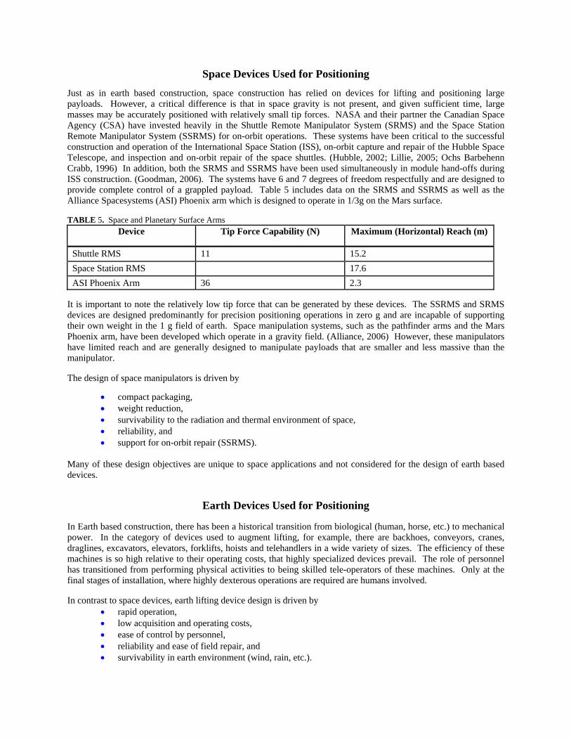
Space Devices Used for Positioning
Just as in earth based construction, space construction has relied on devices for lifting and positioning large payloads. However, a critical difference is that in space gravity is not present, and given sufficient time, large masses may be accurately positioned with relatively small tip forces. NASA and their partner the Canadian Space Agency (CSA) have invested heavily in the Shuttle Remote Manipulator System (SRMS) and the Space Station Remote Manipulator System (SSRMS) for on-orbit operations. These systems have been critical to the successful construction and operation of the International Space Station (ISS), on-orbit capture and repair of the Hubble Space Telescope, and inspection and on-orbit repair of the space shuttles. (Hubble, 2002; Lillie, 2005; Ochs Barbehenn Crabb, 1996) In addition, both the SRMS and SSRMS have been used simultaneously in module hand-offs during ISS construction. (Goodman, 2006). The systems have 6 and 7 degrees of freedom respectfully and are designed to provide complete control of a grappled payload. Table 5 includes data on the SRMS and SSRMS as well as the Alliance Spacesystems (ASI) Phoenix arm which is designed to operate in 1/3g on the Mars surface.
TABLE 5. Space and Planetary Surface Arms Device Tip Force Capability (N) Maximum (Horizontal) Reach (m)
Shuttle RMS 11 15.2 Space Station RMS 17.6 ASI Phoenix Arm 36 2.3
It is important to note the relatively low tip force that can be generated by these devices. The SSRMS and SRMS devices are designed predominantly for precision positioning operations in zero g and are incapable of supporting their own weight in the 1 g field of earth. Space manipulation systems, such as the pathfinder arms and the Mars Phoenix arm, have been developed which operate in a gravity field. (Alliance, 2006) However, these manipulators have limited reach and are generally designed to manipulate payloads that are smaller and less massive than the manipulator.
The design of space manipulators is driven by
• compact packaging, • weight reduction, • survivability to the radiation and thermal environment of space, • reliability, and • support for on-orbit repair (SSRMS).
Many of these design objectives are unique to space applications and not considered for the design of earth based devices.
Earth Devices Used for Positioning
In Earth based construction, there has been a historical transition from biological (human, horse, etc.) to mechanical power. In the category of devices used to augment lifting, for example, there are backhoes, conveyors, cranes, draglines, excavators, elevators, forklifts, hoists and telehandlers in a wide variety of sizes. The efficiency of these machines is so high relative to their operating costs, that highly specialized devices prevail. The role of personnel has transitioned from performing physical activities to being skilled tele-operators of these machines. Only at the final stages of installation, where highly dexterous operations are required are humans involved.
In contrast to space devices, earth lifting device design is driven by • rapid operation, • low acquisition and operating costs, • ease of control by personnel, • reliability and ease of field repair, and • survivability in earth environment (wind, rain, etc.).

A key difference between space based devices and earth based devices is that earth based device design is not dominated by the need to minimize weight or packaging size.
LUNAR SURFACE CAPABILITIES AND DEVICE REQUIREMENTS
This section will review the operational functions needed at a lunar-outpost and discuss the desired features of a device to perform these functions. Key features of the device include operational versatility and mechanical reliability.
Summary of Operational Functions Needed at the Lunar-outpost
Construction at a lunar-outpost and construction at earth sites share many of the same functions. A unique feature of the current exploration plan is the repeated return to the outpost site, making it possible, for the first time in space exploration, to reuse infrastructure multiple times. This enables costs of developing and deploying the infrastructure to be amortized against multiple missions, just as cranes and bulldozers are used on multiple construction projects on earth to reduce overall costs and significantly improve operational efficiency. However, in contrast to devices used for earth based construction, devices used for lunar construction are expected to be utilized less frequently. In addition, specific tasks, such as excavating regolith to cover habitats, are expected to occur less frequently, resulting in the need to develop highly versatile devices that may be productive throughout the outpost’s lifetime by performing a variety of tasks.
All of the previous lunar base studies concentrated on solutions for lifting and handling very large payloads, mainly the habitation and laboratory modules. While large payloads are important, they occur infrequently. More important from an operational point of view are the hundreds of items that must be handled that will be too massive and bulky to be carried by unassisted EVA astronauts, while also being much less massive than a module, i.e. in the 100 kg to 3,000 kg range (see Table 1). It is clear that some sort of device, at a minimum, will be necessary to lift, position and handle these items. Properly designed, the same device can also be used to support a variety of other operations including site preparation, inspection, personnel positioning, servicing and repair functions; capabilities which have received little to no attention in the studies performed to date. (Wingo Woodcock Maxwell, 2007)
Because of the large investment required to develop and test a device for lunar operations, it is critical that the full benefit of the device be realized in operation. This requires a versatile design, capable of providing continued support during outpost buildup and long term operation. Table 6 compares the operations that representative space and earth devices can perform. The SRMS and SSRMS are in-space devices which cannot operate in a gravity field. The Potain IGO10 and Fanuc 2000iA are typical devices created for construction and factory automation. None of these devices are capable of supporting the wide range of operations needed on the lunar surface. Only the designs of the SRMS and SSRMS have addressed compact packaging and redundant operations necessary for space missions. There is a need for a new device, such as the Lunar Surface Manipulation System (LSMS) proposed here, to address the challenges of outpost build-up and long term operations.
TABLE 6. Comparison of Operations Supported by Existing Systems.
Operation LSMS SRMS SSRMS Potain IGO10 Fanuc 2000iA
lift (in-zero g) x x x (in gravity field) x x x site preparation x precision manipulation x x x x inspection x x x x personnel positioning x x x

Desired Implementation and Design Features
Lunar architecture and mission requirements, objectives and constraints, lead to a long list of desired features which in turn, have a significant impact on the final operational implementation and design of a lunar surface manipulation system. To reduce architecture total system cost, there will be a need to limit the number of unique surface systems that have to be developed. Because of the high cost to transport mass from the Earth’s surface to the lunar surface, each system must be as light as possible. Since resources, such as; spare parts, support infrastructure, amount of crew time available, etc. will also be limited and of high value, system durability, simplicity and reliability will all be emphasized.
Key features that should be implementation goals for the LSMS include:
- Versatility: the device should be able to perform a variety of functions, including lifting, manipulation and operating in a fork-lift mode. It would also be desirable to have the ability to perform secondary functions to support site preparation, excavation, regolith emplacement, inspection and repair. This would minimize the number of devices required for surface operations. The device should also be versatile in mounting and emplacement, with the capability to operate from fixed landers, mobile chassis, or a fixed surface site.
- Modularity: the device should be composed of common modular elements (such as joints, links and actuators) that would allow it to be reconfigured to accommodate a variety of payload masses and reach envelopes (by changing both link lengths and number of joints [degrees-of-freedom]). The device configuration will be established on the ground (before launch) to maximize the device capabilities for initial operations. Subsequently, the device could be reconfigured on the lunar surface as the nature of operations changed over the life of the base (without the need for designing and delivering a new device). Using a limited set of modules to construct the device also simplifies maintenance and repair.
- Mechanical Simplicity and Reliablity: the device should be simple from a mechanical standpoint. This improves reliability, as well as simplifies maintenance. Simple mechanisms, actuators, and structures also reduce the impact of the harsh lunar environment on operational reliability.
- Ease of Operations: the device should be able to operate in an automated mode for many tasks to reduce impact on crew time and resources. However, it should also be simple for the crew to operate manually when task complexity or safety dictates.
Key design features to include are:
- Compact packaging: for packaging on the lander and transportation to the lunar surface to maximize payload volume on the lander.
- Self deployable: use its own actuators to deploy itself once on the lunar surface, to preclude the need for any ancillary deployment devices, saving mass and cost.
- Standardized interfaces: At the base, will allow simple attachment and integration with the lander, mobility chassis, and fixed ground support. At the tip, will enable quick tool and end effector changes, allowing for a variety of operations to be performed. Reduces cost since only tools have to be developed and fabricated.
- Self mobility: concepts that have a limited ability to relocate their base will simplify redeploying the device, from a lander to a mobile chassis for example. Self mobility also eliminates the need for (and expense to develop) supporting infrastructure hardware.
- Low mass: concepts that are structurally efficient, with load paths dominated by compression and tension (not bending and torsion) will result in most mass efficient device. Simple load paths that allow polymeric composites to be easily incorporated into the design will also lead to low mass.
- Durability: the lunar environment is very severe and includes: vacuum, cycling between extreme hot and cold temperatures, long exposures to those extreme temperatures, broad spectrum of incident radiation, micro-meteoroid impact threat, and abrasive and electrostatic lunar dust. Structure, mechanism and material concepts
must all be able to withstand long-term exposure to these environmental effects while maintaining structural integrity and operational effectiveness.
LUNAR SURFACE MANIPULATION SYSTEM
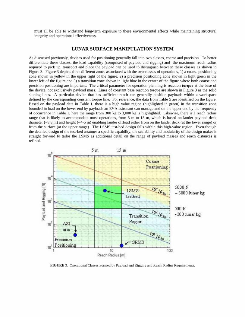
As discussed previously, devices used for positioning generally fall into two classes, coarse and precision. To better differentiate these classes, the load capability (comprised of payload and rigging) and the maximum reach radius required to pick up, transport and place the payload can be used to distinguish between these classes as shown in Figure 3. Figure 3 depicts three different zones associated with the two classes of operations, 1) a coarse positioning zone shown in yellow in the upper right of the figure, 2) a precision positioning zone shown in light green in the lower left of the figure and 3) a transition zone shown in light blue in the center of the figure where both coarse and precision positioning are important. The critical parameter for operation planning is reaction torque at the base of the device, not exclusively payload mass. Lines of constant base reaction torque are shown in Figure 3 as the solid sloping lines. A particular device that has sufficient reach can generally position payloads within a workspace defined by the corresponding constant torque line. For reference, the data from Table 5 are identified on the figure. Based on the payload data in Table 1, there is a high value region (highlighted in green) in the transition zone bounded in load on the lower end by payloads an EVA astronaut can manage and on the upper end by the frequency of occurrence in Table 1, here the range from 300 kg to 3,000 kg is highlighted. Likewise, there is a reach radius range that is likely to accommodate most operations, from 5 m to 15 m, which is based on lander payload deck diameter (~8.8 m) and height (~4-5 m) enabling lander offload either from on the lander deck (at the lower range) or from the surface (at the upper range). The LSMS test-bed design falls within this high-value region. Even though the detailed design of the test-bed assumes a specific capability, the scalability and modularity of the design makes it straight forward to tailor the LSMS as additional detail on the range of payload masses and reach distances is refined.
FIGURE 3. Operational Classes Formed by Payload and Rigging and Reach Radius Requirements.

LSMS Overview and Description (Hybrid)
The LSMS has been specifically designed with the features of the previous section and the operational capabilities of Table 6 in mind. The LSMS is modular; both single and multiple segment booms and king posts may be used. A single segment boom version of the LSMS is shown in Figure 4 unloading a lander. The LSMS provides a variety of functional capabilities, many of which have been historically supplied by the SRMS and SSRMS. A test-bed for the LSMS is under development to verify the structural design concept, packaging, and operational versatility of the design. An image of the crane test-bed, currently being constructed, is shown in Figure 5. As shown in Figure 5, the test-bed consists of three primary compression members (starting at the base) named the kingpost, arm and forearm; four secondary compression members (spreader bars) and 4 tension diagonal rods. The test-bed has three degrees of freedom; rotations at the waist, shoulder and elbow, with shoulder and elbow joints actuated by hoist1 and hoist2 respectively, while the waist is actuated by a rotary motor. The LSMS is designed with the structural efficiency of a crane, yet the test-bed retains the ability for precise placement of payloads by including an articulated main boom. The versatile multi-purpose design includes a tool interface at the tip allowing the LSMS to acquire a variety of end-effectors such as hoists, pallet forks, grapples, etc. for specific precision operations. It also features a method to easily relocate the base.
FIGURE 4. Artist Concept of LSMS Unloading Lander. FIGURE 5. CAD Model of Test-bed.
The LSMS represents the first device designed for operations in the transition region of Figure 3. Unlike the SRMS and SSRMS, that have near equal structural stiffness in all directions, the LSMS is optimized for a gravity field, concentrating its structural mass to resist the gravity load, as do earth based crane. The target design for the test-bed, shown in Figure 4, captures the majority of the expected range of payload masses and reach distances for lunar surface operations.
The LSMS is designed with a far greater joint angle range than conventional cranes shown in Figure 1. This enables a much broader range of operational configurations, such as the fork-lift mode illustrated in Figure 6, which is the prelude to self unload or removing payloads from the side of a lander. Operational control over the elbow angle is a novel feature of the LSMS that enables rigid grappling of payloads by allowing the boom tip to be placed on the payload with subsequent precise control over the payload position. In addition, control of the elbow angle enables the hoist line to autonomously attach to the payload, a critical capability to reduce the need for support personnel. The ability to acquire tools greatly enhances the versatility of the LSMS, enabling sensor scans of the lander prior to removing payloads, sensor scans of the ascent vehicle prior to launch (Figure 7), acquisition of grapples to unload the lander, acquisition of drag lines to move regolith in support of berm building, ISRU supply, habitat covering, road building, reactor shielding, etc.
The majority of the components of the LSMS, shown in Figure 5, are designed to act as a truss, one of the most efficient structural forms for large spans. In a truss, the structural members experience pure tension and compression, no bending. The LSMS’s modular design enables additional structural members or degrees of freedom to be added in situ to accommodate changing lifting requirements. In addition, the LSMS can use special
LSMS with One-Link Boom
kingpost
armforearm
waist rotation
shoulder rotation elbow rotationhoist 2
hoist1
spreader (1 of 4)

purpose end-effectors to enhance its operational capabilities. The LSMS design employs numerous features providing superior performance for transport to and operation in the harsh lunar environment including:
• light weight design with compact packaging for launch, • large articulation range supporting direct contact with payload and the ability to insert or withdraw
payloads horizontally, • packaging offset at top of king post reduces required length of the horizontal spreader at the top of the
kingpost and improves packaging. • no pulleys (to minimize rotating components) improving robustness to the harsh lunar dust
environment, • non-collocated joints and actuators, like a crane, which significantly reduces the weight of the actuator
because of the mechanical advantage its placement provides, • modularity of the individual compression members. The members may be quickly interchanged with
different length members or additional members added to accommodate in-situ changes in lifting needs.
• isolation and distribution of the actuation elements. This enables the actuators to be completely enclosed to protect against the harsh lunar environment and facilitates rapid upgrade or periodic replacement.
• multi-segment articulated boom. A single degree of freedom along the boom is shown in Figure 4, though the design directly supports multiple links to accommodate complex lifting geometries. (Figures 6 and 7)
• variable number of spreaders at joints which may be optimized for articulation angles required, • spreader lift off for improved mechanical advantage over larger articulation range. Lift off refers to the
cable attachment at the top of the spreaders, which will lift off the spreader(s) as shown in Figure 6, • square compression tubes maximize area moment of inertia for a given cross section in the folded
state, • unique design directly applicable to composite compression and tension members for reduced system
mass, • minimum cable length with the remaining actuator line of action established by solid rods to improve
precision positioning and • quick change at the tip and base to accommodate variety of end-effectors (tools) and support base
repositioning.
FIGURE 6. Fork-Lift Mode used to Remove Tanks from Under Lander. FIGURE 7. Inspection of Ascent Module.
LSMS Hoist Cable has Lifted off Spreaders
Inspection Package

LSMS Test-Bed Design Detail
The objective of the LSMS test-bed, Figure 5, is to: 1) validate models used to analyze the novel LSMS design, 2) develop and validate control stratigies for the LSMS and 3) test techniques for acquiring and manipulating payloads, including precision placement and horizontal grappling. The test-bed has a reach radius of 7.5m and a lunar lift capability of 1000 kg. Referring to Figures 5 and 8, two hoists are used to actuate the joints through tension cables, cable1 and cable2. The cable length for the hoists is set by the range of motion of the respective joint, with the remainder of the connection formed by a rigid rod to improve fine positioning. The rigid rod has a higher stiffness than the section of cable it replaces because it does not sag.
LSMS Mass Estimation and Member Sizing
To estimate the mass of the LSMS for different operational requirements, the following equations have been developed. These equations correlate favorably with the detailed hardware design, although a detailed comparison is premature at this stage of the hardware construction and assembly. The sizing rules are based on the idealized design shown in Figure 8 where the LSMS has a clear height of ηR while supporting a weight of W at a radius R. The loads in the individual members are shown by the equations in black. Hoists actuating cables 1 & 2 control rotation of the shoulder and elbow joints and a third motor controls rotation at the waist.
FIGURE 8. Test-bed Approximation Used for Sizing.
The LSMS test-bed reach of 7.5 m and boom height of 3.75 m ( R and ηR in Figure 8) were selected to accommodate tests planned at approximately 40% to 50% scale. These dimensions must be selected to meet operational requirements before the device mass may be estimated. With the reach and boom height set, the general scheme for estimating the mass of the LSMS is to determine the king post cross section dimensions and thickness to avoid buckling and provide adequate wall thickness to resist damage due to impact. The spreader length, b, was selected as 1.3 m which represented a compromise between operational footprint, hoist size, packaging efficiency, and spreader weight. A detailed trade study to optimize this parameter has not been performed.
t
AA dc
section BB
BB
sectionAA
R
ηR
b
b
W
a
a
RWb
2RWb
W
RWb
RWb
2RWb
1RWb
⎛ ⎞+⎜ ⎟⎝ ⎠
22
2R b
Wb
⎛ ⎞ +⎜ ⎟⎝ ⎠
dd section CC
CC
cable2
cable1
diagonal rod(1 of 4)

Euler Buckling constrains kingpost design, according to
2
24tube tube
Eulertube
E IPFS L
π= , (1)
where PEuler is the buckling load, tubeE is the modulus of elasticity of the material, tubeI is the limiting moment of inertia of the cross section, FStube is the factor of safety, and L is
L b Rη= + , (2)
where η is the ratio of the king post length to R . The test-bed uses square cross section members to maximize the moment of inertia, I, for a given packaging volume and thus I can be approximated by
323
I a t= , (3)
where a is the average size of the square tube cross section and t is the thickness as shown in section AA of Figure 8. t is selected based on operational and handling considerations, essentially a minimum gage design constraint, however it is important to note that as t is reduced, a increases leading to a larger packaged volume. Using the load in the king post as a function of W, as given in the figure, and equating it to EulerP of Equation 1 (ignoring the load in the king post diagonal rod) and substituting Equations 3 and 2 into 1 and solving for cross section size leads to
13
2
32
( ) 16
tube
tube
RFS R b Wba
E t
η
π
⎛ ⎞⎛ ⎞+ +⎜ ⎟⎜ ⎟⎝ ⎠⎜ ⎟=⎜ ⎟⎜ ⎟⎝ ⎠
. (4)
The tube mass, tubesM , assuming all compression members are the same size, is given by
( )4tubes tubes tube jointM a t L ρ β= , (5)
where tubesL is the total length of compression tubes, tubeρ is the density of the tube material, jointβ is a factor to
account for the joint weight. tubesL is given by
3tubesL R R bη= + + . (6)
Similarly the following expression can be developed for the cable mass, cM , for cables 1 and 2 in Figure 8. The
load in cable2 is ½ that of cable1 and thus cM can be expressed as:
( )1 2 32 2c c c hoist
RM A R dρ η π⎛ ⎞⎛ ⎞= + +⎜ ⎟⎜ ⎟⎝ ⎠⎝ ⎠. (7)
where cρ is the cable density, cA is the cross sectional area of the cable and hoistd is the diameter of the hoist
drum. The factor ( )2 3 hoistd π accounts for 3 wraps of cable around the hoist drum and that there are 2 hoist
drums. The cable diameter cd (illustrated in section BB of Figure 8) for cable1 is determined from

max
max
2 c cc
c
b W R FSd
bσ π
σ π= . (8)
where max cσ is the maximum allowable stress in the cable and cFS is the factor of safety for the cables. The minimum hoist diameter to cable diameter ratio is taken as 20, based on bending restrictions given by Shapiro (Shapiro Shapiro Shapiro, 1991). This allows direct computation of the cable mass using Equation 8 to calculate the cable diameter, multiplying by 20 and substituting into Equation 7. Similarly the mass of the diagonal rods can be calculated from
( )2 2 2 2 2 24 2d d dM A R b R b bρ η= + + + + . (9)
The diagonal rod area, Ad, is determined by calculating the diameter, dd, similar to Equation 8. Solid rods are used, as shown in section CC of Figure 8, which result in a lighter weight design compared to cables because it is possible to take advantage of higher performance materials with associated safety factors. Finally, the actuator mass aM (including motor, hoist drum, gear box, and mounting hardware) is estimated using
1.5 aa
a
MKτ
= , (10)
where the factor 1.5 corresponds to the sum of 1 for hoist1 and 0.5 for hoist2 which experiences ½ the load of hoist1. In Equation 10, aτ is the required torque of the hoist1 motor and aK is an actuator mass constant with units
of N-m /kg. An additional factor of 0.3 a
aKτ is included in the total mass calculation for the waist rotary joint, which
experiences no direct payload induced load and must only overcome joint friction. Assuming the hoist motor is located on the rim of the hoist drum, the motor torque can be calculated for hoist1 and is given by
2
hoista
W R db
τ = . (11)
Thus, the total crane mass is estimated by the sum of Equations 5, 7, 9 and 10 along with 0.3 a
aKτ for the waist
actuator.
The crane packaging volume can be estimated from R, b and a of Equation 4. The packaged volume V is approximated by
3.2max ,2RV R aη⎛ ⎞= ⎜ ⎟
⎝ ⎠, (12)
where the factor 3.2 results from folding the unit into 3 equal length parts, king post, arm and forearm as shown in Figure 9 and the 0.2 is an estimate for the spreaders and motor volume fraction.
FIGURE 9. LSMS in Packaged Configuration.
forearm
kingpost
arm
spreaders
Test-Bed Validation
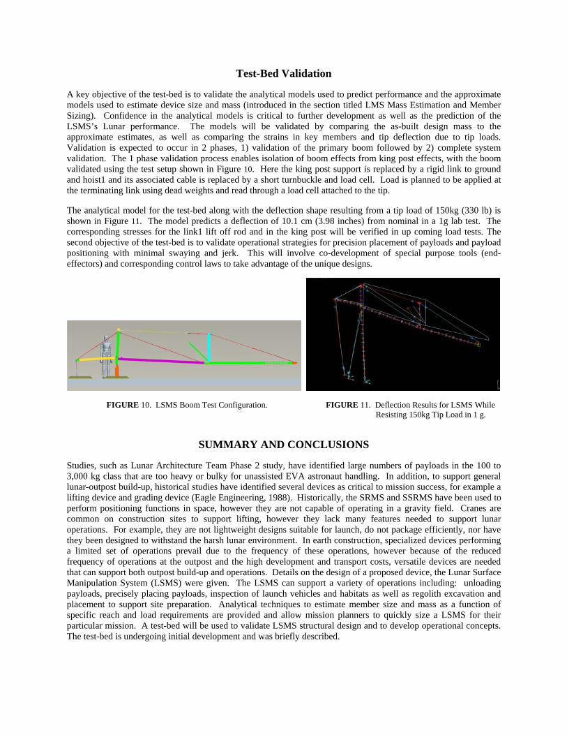
A key objective of the test-bed is to validate the analytical models used to predict performance and the approximate models used to estimate device size and mass (introduced in the section titled LMS Mass Estimation and Member Sizing). Confidence in the analytical models is critical to further development as well as the prediction of the LSMS’s Lunar performance. The models will be validated by comparing the as-built design mass to the approximate estimates, as well as comparing the strains in key members and tip deflection due to tip loads. Validation is expected to occur in 2 phases, 1) validation of the primary boom followed by 2) complete system validation. The 1 phase validation process enables isolation of boom effects from king post effects, with the boom validated using the test setup shown in Figure 10. Here the king post support is replaced by a rigid link to ground and hoist1 and its associated cable is replaced by a short turnbuckle and load cell. Load is planned to be applied at the terminating link using dead weights and read through a load cell attached to the tip.
The analytical model for the test-bed along with the deflection shape resulting from a tip load of 150kg (330 lb) is shown in Figure 11. The model predicts a deflection of 10.1 cm (3.98 inches) from nominal in a 1g lab test. The corresponding stresses for the link1 lift off rod and in the king post will be verified in up coming load tests. The second objective of the test-bed is to validate operational strategies for precision placement of payloads and payload positioning with minimal swaying and jerk. This will involve co-development of special purpose tools (end-effectors) and corresponding control laws to take advantage of the unique designs.
FIGURE 10. LSMS Boom Test Configuration. FIGURE 11. Deflection Results for LSMS While Resisting 150kg Tip Load in 1 g.
SUMMARY AND CONCLUSIONS
Studies, such as Lunar Architecture Team Phase 2 study, have identified large numbers of payloads in the 100 to 3,000 kg class that are too heavy or bulky for unassisted EVA astronaut handling. In addition, to support general lunar-outpost build-up, historical studies have identified several devices as critical to mission success, for example a lifting device and grading device (Eagle Engineering, 1988). Historically, the SRMS and SSRMS have been used to perform positioning functions in space, however they are not capable of operating in a gravity field. Cranes are common on construction sites to support lifting, however they lack many features needed to support lunar operations. For example, they are not lightweight designs suitable for launch, do not package efficiently, nor have they been designed to withstand the harsh lunar environment. In earth construction, specialized devices performing a limited set of operations prevail due to the frequency of these operations, however because of the reduced frequency of operations at the outpost and the high development and transport costs, versatile devices are needed that can support both outpost build-up and operations. Details on the design of a proposed device, the Lunar Surface Manipulation System (LSMS) were given. The LSMS can support a variety of operations including: unloading payloads, precisely placing payloads, inspection of launch vehicles and habitats as well as regolith excavation and placement to support site preparation. Analytical techniques to estimate member size and mass as a function of specific reach and load requirements are provided and allow mission planners to quickly size a LSMS for their particular mission. A test-bed will be used to validate LSMS structural design and to develop operational concepts. The test-bed is undergoing initial development and was briefly described.

NOMENCLATURE & ACRONYMS
ASI = Alliance Spacesystems Inc. CE&R = Concept Exploration and Refinement DOF = Degree of Freedom ESAS = Exploration Systems Architecture
Study EVA = Extravehicular Activity ISS = International Space Station LAT-2 = Lunar Architecture Team phase II LSMS = Lunar Surface Manipulation System NASA = National Aeronautics and Space
Administration SRMS = Shuttle Remote Manipulator System SPR = Small Pressurized Rover SSRMS = Space Station Remote Manipulator
System a = average size of the cross section
cA = cross sectional area of cables
dA = cross sectional area of diagonal rod
b = spreader length
jointβ = factor to account for the joint weight.
cd = diameter of the hoist cable
dd = diameter of the diagonal rod
hoistd = diameter of the hoist drum
tubeE = modulus of elasticity of the material
FSc = cable factor of safety FStube = compression tube factor of safety
tubeI = limiting moment of inertia of the compression cross section
aK = actuator mass constant [N-m/kg] L = the length of the Kingpost
tubesL = total length of compression tubes
cM = mass of the hoist cables
dM = mass of the diagonal rods
tubesM = mass of compression members
η = ratio of the king post length to R PEuler = buckling load of king post R = maximum radius of the LSMS
cρ = density of cable material
tubeρ = density of the tube material
max cσ = maximum allowable stress in the cable t = thickness of compression members
cross section
aτ = required torque of the hoist motor V = packaged volume
REFERENCES
Adinolfi, P.J.; Heinz, F.A. Jr: “Design Study of Special Purpose Systems For the Lunar Surface,” NASA CR-61077, April 30, 1965.
Alliance Space Systems press release on 8/10/2006, Accessed 9/11/2007. http://www.alliancespacesystems.com/index.php?option=com_content&task=view&id=123&Itemid=129
Bodkin, D.K., Escalera, P., and Bocam, K.J. “A Human Lunar Surface Base and Infrastructure Solution,” Presented at the AIAA Space 2006 Conference, 19 – 21 September 2006, San Jose, CA, AIAA 2006-7336.
Connolly, J.F.; “Design of a Minimum Level Lunar Base Infrastructure,” Presented at the AIAA 1992 Aerospace Design Conference, February 3 – 6, 1992, Irvine CA, AIAA 92-1034.
Eagle Engineering, “Lunar Surface Construction & Assembly Equipment Study: Lunar Base Systems Study Task 5.3,” NASA-CR-172105, September, 1988.
Goodman, J.L. “History of Space Shuttle Rendezvous and Proximity Operations,” Journal of Spacecraft and Rockets, Vol. 43, No. 5, September-October 2006, pp. 994-959.
Hubble, Servicing Missions, 1993-2002, http://hubblesite.org/sci.d.tech/team_hubble/servicing_missions/ Accessed 9/11/2007. Lillie, C.F. On-Orbit Servicing for Future Space Observatories, Presented at Space 2005 Conference, Long Beach Ca., Sept.
2005. AIAA 2005-6609. NASA, “The Vision for Space Exploration,” NP-2004-01-334-HQ, 2004. NASA, “NASA’s Exploration Systems Architecture Study,” Final Report, NASA-TM-2005-214062, 2005. Ochs, W., Barbehenn, G and Crabb, W.. “The Hubble Space Telescope Servicing Missions: Past, Present, and Future
Operational Challenges,” SpaceOps 96, September 1996. Shapiro, H.I., Shapiro, J.P., and Shapiro, L.K. Cranes and Derricks 3rd Edition, McGraw-Hill, 1991. Wingo, D.R., Woodcock, G. and Maxwell, M. “Lunar-outpost Development and the Role of Mechanical Systems for Payload
Handling, Final Report,” Deliverable Under Contract NNL06AE27P, NASA Langley Research Center, February 10, 2007.