a virtual prototyping environment for parallel kinematic
TRANSCRIPT

A Virtual Prototyping Environment for Parallel Kinematic MachineAnalysis and Design
Keywords: PKM, Multi-body Analysis, Virtual Prototyping
Giacomo Bianchi (contact author), Irene Fassi, Lorenzo Molinari TosattiITIA-CNR, Viale Lombardia 20/A, 20131 Milano, Italy
Tel:+39-02-70643911, Fax: +39-02-70643915, email: [email protected] Catelani
Mechanical Dynamics s.r.l Italy, Via Palladio 98, I-33010 Tavagnacco (Udine), Italy
AbstractIndustrial adoption of PKMs may be eased by availability of methodologies and integrated tools ableto analyze in a short time PKMs of any architecture, providing the key data needed to design themachine. The proposed Virtual Prototyping Environment for PKM Analysis answers to theserequirements, quickly estimating not only the reachable workspace, the Jacobian conditioning, butalso the actuators’ effort, internal loads in the mechanical structure and the effects of lumpedstructural compliances. A description of the developed VPE-PKM, based on a commercial Multi-body package, is given. Its effectiveness is shown presenting results obtained by ITIA-CNR during thedesign of a 3 dof translational PKM for light deburring operations.
1 INTRODUCTIONParallel Kinematic Machines promiseinteresting performances, compared to serialmachines mechanisms, under several aspects[Heisel, Moriwaki, Neugebauer et al.,Pritschow, Sohlenius, Tönshoff et al, Weck etal. in 1; 2; 3] and in fact the industrial interesthas been continually growing [4]. Nevertheless,industrial applications are still confined to a fewdomains. A possible motivation, in addition tothe ones presented in [Koren in 1; 5], may bethe difficulty, in the first steps of design, to find,among the quite infinite variety of possibleconfigurations in terms of strut and jointstypology and location, the most suitable one forthe given application [2, 3]: to respond tocurrent and future industrial requirements onPKM design, a methodology, supported bypowerful, integrated software tools, is required.Several works have been done toward thisdirection providing either a systematic
methodology for the design of different PKMs’topologies [6], or software tools for the optimaldesign of a specific PKM class (typically, theStewart platform like mechanisms) [7; 8; 9;Tsai, Ji et al. in 1].The problem of developing an appropriatemethodology and related ‘Integrated Analysis &Design Tool’ (IADT) has been tackled by ITIA-CNR, within several European and NationalResearch Programs [10-14], as a fundamentalpart of studying new industrial applications ofPKMs in different sectors. The effort producedto date has lead to the development of amethodological approach [15] and severalsoftware tools, among them the MathematicalEvaluation Environment (MEE) [16] and theMulti-body Virtual Prototyping Environmentfor Parallel Kinematic Machines Analysis andDesign (Multi-body VPE-PKM) (Fig. 1), whichhave been used and tested during the wholedesign process, from the conceptual to theprototyping step, of different PKMsarchitectures.

Basically, the MEE systematizes the typicalanalysis steps followed when a new PKMarchitecture is being conceived: write by handthe kinematic equations, solve them eithermanually or by an analytic/numerical softwaretool, evaluate the workspace and identifysingularities using computationally optimizedsoftware routines [Negri et al. in 1; 16] andabout the kineto-static behavior of the machine.The developed routines are very effective inevaluating, in few minutes, several geometricvariants of different machine architectures(topologies), but they require a considerableprogramming effort for each new machinetopology and become very complex when it isrequired to evaluate the dynamic behavior, theinternal loads in the machine structure or thesensitivity to manufacturing and assemblyerrors.The VPE-PKM has been designed to overcomethese limitations and to fulfill the followingrequirements:
1) Generality. Applicable to any existing orcompletely new topology of PKM.
2) Completeness. It should support the users inthe key steps of mechanical design, giventhe application requirements: architectureselection, geometry optimization, actuatorsizing, mechanical structure design.
3) Quick response. It should provide answerswith the short timing typical of an industrialproduct development. In fact, it should beused in the first design phases, when it isnecessary to rapidly configure and evaluateseveral architectures .
The VPE-PKM satisfies these requirementsjoining the power of a commercial multi-bodysoftware (ADAMSTM, MDInc) with theefficiency of PKM-specific analysis routines(implemented in MatlabTM, The MathWorks,Inc.).The paper is structured in the following way: inSection 2 the VPE-PKM architecture ispresented, in Section 3 the industrial application
used as an example through the paper isdescribed, in Section 4 the analyses performedby VPE-PKM are illustrated, explaining the keyimplementation issues, while in Section 5 thefinal remarks and conclusions are given.
Robot
User Interface
Different analysis strategies
Automatic analysis
Data extraction
Model Based Approach
Post-processing
Multi-body VPE-PKMAD
Maple
Matlab
MEE
Fig.1. From the Conception Stage to the Prototypingand Industrial Application using the proposedMulti-body VPE-PKM and the MEE
2 VPE-PKM ARCHITECTUREThe kinematic analysis based on the evaluationof the Jacobian matrix (core of the MEE) iscrucial for PKM design but it is not sufficient tocomplete the analysis of a real machine. In fact,actuators must not only counteract all externalloads applied to the end-effector (as evaluatedby the Jacobian), but also work to support themachine weight, balance the inertial forces andwin unavoidable joint friction. It is alsoimportant to evaluate loads in critical points ofthe machine structure. This is particularly truefor machines with less than six degrees offreedom, because in this case part of the forcesapplied to the end-effector «flows» to groundthrough the structure, without loading anactuator. It was thereafter decided to developthe VPE-PKM customizing a general purposemulti-body analysis software with a set of “adhoc” routines and related user interfacesdedicated to the virtual prototyping of a PKM.The key features of the multi-body analysispackage exploited by VPE-PKM are:

• Complete and Customizable 3D GraphicalUser Interface for manipulator modeling andvisualization
• Automatic generation of kinematic anddynamic equations of motion
• Static equilibrium computation• Model linearization and generation of a
State Space representation (ABCD matrices)
Commercial multi-body analysis softwares canbe used directly to analyze a PKM performingstandard simulations [17,23]; the VPE-PKMstrongly increases the efficacy of such a solutionadding the following PKM-specific capabilities:
• dedicated user interface for a quick andconsistent model set-up (e.g. to define jointlimitations)
• repetitive analyses automation forworkspace identification and scanning (e.g.stiffness mapping on a selected grid ofpoints)
• specific strategies for PKM analysis notimplemented in the multi-body environment(e.g. Jacobian evaluation)
• post-processing of the raw data provided bythe Multi-Body analyses, using efficientmathematical routines
• complete and intuitive 2D and 3D graphicalrepresentations of results
The VPE-PKM permits the following analyses:
• Interference analysis: actual workspacedetermination (considering active andpassive joint’s limits)
• Jacobian analysis: singularities andnumerical conditioning
• Actuator effort: due to external forces,machine weight, inertial forces, joint friction
• Loads in the structure due to externalforces and machine weight
• Error analysis: tool displacement due tostructural deformations or manufacturingerrors
• Compliance at the tool due to lumpedcompliances anywhere in the structure.
Fig.2. VPE-PKM architecture
3 INDUSTRIAL CASE STUDYIn order to clarify the functionality of the VPE-PKM, the design steps are illustrated using alsonumerical examples, all based on the analysesperformed to design an industrial prototype forlight deburring operations in shoemanufacturing, currently being built at ITIA-CNR. The process requirements asked for a 3dof translational PKM, the orientations of theend effector being given by a serial wristmounted on the mobile platform. The finallayout of the optimized machine is shown inFig.3. Other process requirements aresummarized in Tab. 1.
Max. external force on E.E. 80 NMax. external torque on E.E. 20 NmMax E.E. speed 0.5 m/sMax E.E. acceleration 5 m/s2
MB package:
• free model building
• guided setup for PKM analysis
• automatic analysis & linearization
Matematical package:
• jacobian computation & analysis
• worst case identification (SVD)
• plots
raw data
MB package:
• free model building
• guided setup for PKM analysis
• automatic analysis & linearization
Matematical package:
• jacobian computation & analysis
• worst case identification (SVD)
• plots
raw data

Max E.E. positioning error 0.1 mmTab.1. Process Requirements (E.E. : End Effector)
A3A2
A1
B3B2B1U
V
W
V
X
Y
Z
Y
Z
YZ
X
Z
X
Strut_2 Strut_3
Strut_1
O
0I
0I
O
Fig.3. The 3 dof translational PKM designed andanalyzed with the VPE – PKM
The proposed design has been evaluatedanalyzing the machine behavior over a grid of105 points, covering the following ranges alongthe coordinate axes:
axis N. of points Range [mm]X 5 -180 : 140Y 3 -80 : 80Z 7 -240 : 240
4 MODEL SETUP AND ANALYSIS
4.1 Model set-upThe Multi-body VPE-PKM has been developedwith the idea of maintaining the generality ofthe multi-body simulation environment. For thisreason the machine model has not to be chosenfrom a set of existing parametric families, butcan be freely built using all the elementsprovided by the Multi-body environment.
End-effectorand
related reference frame
Mechanical limits on
passive joints
ActuatorsMechanical limits on active joints
Internal loads to be evaluatedLumped compliance
and dimensional errors in the structure
Base and
related reference frame
Fig.4. Standard objects that the user must define duringthe model set-up phase
In order to analyze a general machine with theVPE-PKM, the user must define, through thecustom user interface, only a coordinate frameassociated to the end effector and indicate whichjoints are actuated (Fig.4).
4.2 Workspace evaluationIn order to identify the machine workspace, theuser have to define, for each joint, the allowedmotion range (Fig.5): only local interference injoints are considered.
Allowable rotation
Fig. 5. Definition of the mechanical limits on active andpassive joints
The space can be explored using differentstrategies, always based on space discretization:1. Moving along a given sequences of machine
poses (Pose following: Fig. 6). It is useful toverify the execution of point-to-point pathsrequired by the application and also toquickly evaluate the machine at a restrictedset of poses, before running more exhaustivesearches. If a pose is not reachable thenearest reachable one is determined and thesix dimensional distance evaluated.
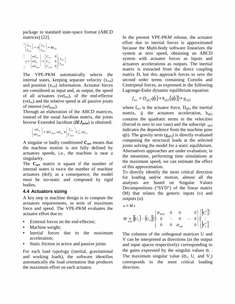
2. Moving the machine in different directions,along a set of rays ordered following aspherical (Spherical scanning) or cylindrical(Cylindrical scanning) geometry, until aninterference occurs (Figs. 7 and 8).
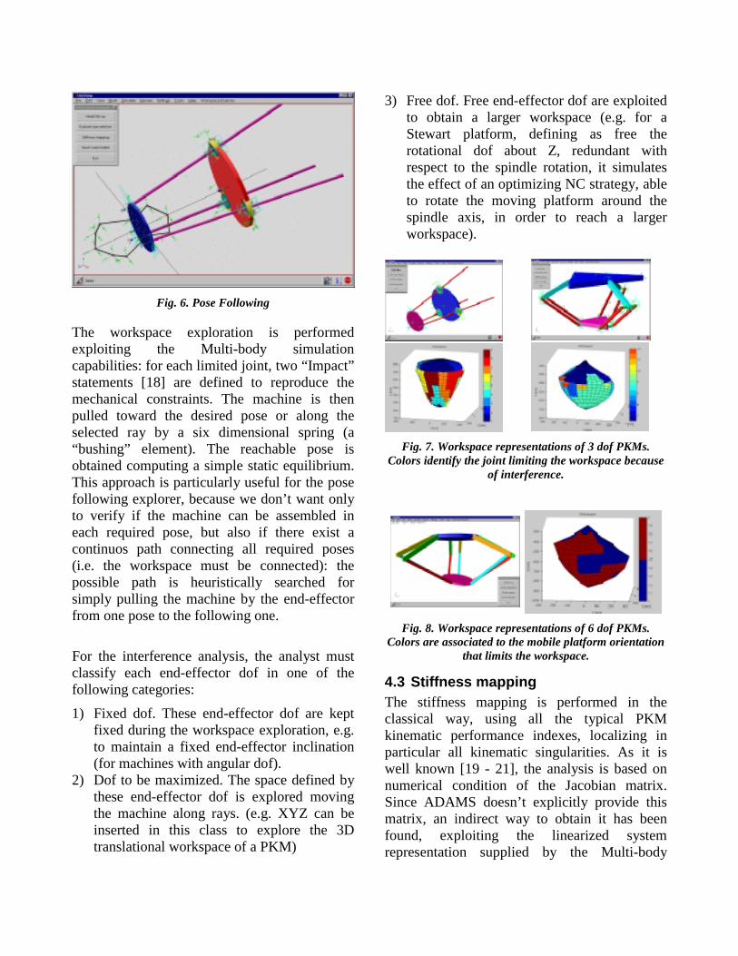
Fig. 6. Pose Following
The workspace exploration is performedexploiting the Multi-body simulationcapabilities: for each limited joint, two “Impact”statements [18] are defined to reproduce themechanical constraints. The machine is thenpulled toward the desired pose or along theselected ray by a six dimensional spring (a“bushing” element). The reachable pose isobtained computing a simple static equilibrium.This approach is particularly useful for the posefollowing explorer, because we don’t want onlyto verify if the machine can be assembled ineach required pose, but also if there exist acontinuos path connecting all required poses(i.e. the workspace must be connected): thepossible path is heuristically searched forsimply pulling the machine by the end-effectorfrom one pose to the following one.
For the interference analysis, the analyst mustclassify each end-effector dof in one of thefollowing categories:
1) Fixed dof. These end-effector dof are keptfixed during the workspace exploration, e.g.to maintain a fixed end-effector inclination(for machines with angular dof).
2) Dof to be maximized. The space defined bythese end-effector dof is explored movingthe machine along rays. (e.g. XYZ can beinserted in this class to explore the 3Dtranslational workspace of a PKM)
3) Free dof. Free end-effector dof are exploitedto obtain a larger workspace (e.g. for aStewart platform, defining as free therotational dof about Z, redundant withrespect to the spindle rotation, it simulatesthe effect of an optimizing NC strategy, ableto rotate the moving platform around thespindle axis, in order to reach a largerworkspace).
Fig. 7. Workspace representations of 3 dof PKMs.Colors identify the joint limiting the workspace because
of interference.
Fig. 8. Workspace representations of 6 dof PKMs.Colors are associated to the mobile platform orientation
that limits the workspace.
4.3 Stiffness mappingThe stiffness mapping is performed in theclassical way, using all the typical PKMkinematic performance indexes, localizing inparticular all kinematic singularities. As it iswell known [19 - 21], the analysis is based onnumerical condition of the Jacobian matrix.Since ADAMS doesn’t explicitly provide thismatrix, an indirect way to obtain it has beenfound, exploiting the linearized systemrepresentation supplied by the Multi-body
package in standard state-space format (ABCDmatrices) [22].
�
�
�
��
���
���
�
�
�
=�
��
�
��
��
�
=
+��
���
=��
���
pos
vel
pass
ee
act
pass
ee
act
actpos
vel
pos
vel
xx
CCC
velvelvel
y
Buxx
Axx
000
�
�
The VPE-PKM automatically selects theinternal states, keeping separate velocity (xvel)and position (xvel) information. Actuator forcesare considered as input and, as output, the speedof all actuators (velact), of the end-effector(velee) and the relative speed at all passive jointsof interest (velpass).Through an elaboration of the ABCD matrices,instead of the usual Jacobian matrix, the jointsInverse Extended Jacobian (IEJjoint) is obtained:
actactpass
eeact
pass
ee velCCC
velIEJvelvel 1
joints−�
��
�≡=�
�
��
A singular or badly conditioned Cact means thatthe machine motion is not fully defined byactuators speeds, i.e., the machine is near asingularity.The Cact matrix is square if the number ofinternal states is twice the number of machineactuators (dof); as a consequence, the modelmust be iso-static and composed by rigidbodies.4.4 Actuators sizingA key step in machine design is to compute theactuators requirements, in term of maximumforce and speed. The VPE-PKM evaluates theactuator effort due to:
• External forces on the end-effector;• Machine weight;• Inertial forces due to the maximum
acceleration;• Static friction in active and passive jointsFor each load typology (inertial, gravitationaland working loads), the software identifiesautomatically the load orientation that producesthe maximum effort on each actuator.
In the present VPE-PKM release, the actuatoreffort due to inertial forces is approximatedbecause the Multi-body software linearizes thesystem at zero speed, obtaining an ABCDsystem with actuator forces as inputs andactuators accelerations as outputs. The inertialmatrix is extracted from the direct couplingmatrix D, but this approach forces to zero thesecond order terms containing Coriolis andCentripetal forces, as expressed in the followingLagrange-Euler dynamic equilibrium equation:
( ) ( ) ( ) ( )( ) ( )tqtqtqact gtqhtqDf ++= ���
where fact is the actuator force, Dq(t) the inertialmatrix, q�� the actuators acceleration, hq(t)
contains the quadratic terms in the velocities(forced to zero in our case) and the subscript .q(t)indicates the dependence from the machine poseq(t). The gravity term (gq(t)) is directly evaluatedcomputing the structural loads at the selectedjoints solving the model for a static equilibrium.Alternatives approaches are under evaluation; inthe meantime, performing time simulations atthe maximum speed, we can estimate the effectof this approximation.To directly identify the most critical directionfor loading and/or motion, almost all theanalyses are based on Singular ValuesDecompositions (“SVD”) of the linear matrix(M) that relates the generic inputs (v) andoutputs (u):
{ } { }[ ][ ]
[ ]
�
���
�
�
⋅����
���
�
�
⋅=
=
Tn
TMAX
mSVDV
VUUM
vMu
����
1
min
1
000000000
σ
σ
The columns of the orthogonal matrices U andV can be interpreted as directions (in the outputand input spaces respectively) corresponding tothe gains expressed by the singular values σi .The maximum singular value (σ1, U1 and V1)corresponds to the most critical loadingdirection.

In friction evaluation for actuator sizing, onlyCoulomb-like friction (i.e. ( )relVsignAF ⋅= jointjointfrict
)with a constant pre-load is considered. In thiscase, because of the problem non-linearity, theSVD approach cannot be used to identify themotion that requires the maximum actuatoreffort, but it can be shown that the worst case isrequired when all other actuators are standingstill (in this case the active actuator must workagainst all related joints with friction).Actuator sizing routines provide the followingdata for our test case:
Max. act. Speed 0.5 m/sMax. act. Thrust 940 N
Tab.2. Actuator sizing
M NM OM PM QM RM SM TM UM VMM
NMM
OMM
PMM
QMM
RMM
SMM
TMM
UMM
VMM
NMMM
^å~äóòÉÇ=mçëÉ
cçê
ÅÉë=
xkz
^Åíì~íçê=N=iç~Ç=áå=tçêëí=póëíÉã=`çåÇáíáçå=
qççä=cçêÅÉ=bÑÑÉÅídê~îáíó=bÑÑÉÅí===fåÉêíá~ä=bÑÑÉÅí==
Fig. 9. Stacked bar chart of the maximum loads on strut1 actuator.
The maximum required force is represented inFig. 9, for strut 1 actuator, showing both thevariability along the used mesh and the relativerelevance of efforts due to external loads,inertial forces and machine weight. It can beseen, as common for high speed machinesexecuting light operations, that the effect ofexternal loads is not sufficient to correctlychoose the actuator.4.5 Internal Structural LoadsThe internal loads analysis can be interpreted asa generalization of the actuator load analysis,
thinking to have “fictitious actuators” locatedwhere the internal loads have to be computed.We can thereafter define an “ Internal LoadsExtended Jacobian” (“EJint”), that links theforces on the end-effector with the loads on thefictitious actuators:
eefEJf intint =The EJint cannot be obtained from Multi-bodypackage using the ABCD approach used before,because, at the moment, joint reactions cannotbe defined as system outputs duringlinearization. The EJint matrix is therefore builtby the VPE-PKM applying one at a time aforce/torque on the end-effector (X, Y, Z, RX,RY, RZ) and computing the joint reactions (by astatic equilibrium).The EJint is used to find, for each reaction, theworst load case, by SVD.
The internal loads analysis is particularlyimportant for the examined machine, becausethree degrees of freedom of the end-effector arepassively constrained by the mechanicalstructure, provoking both bending and torsion ineach strut.These loads have been computed for each strut,at the position where the actuator is located(represented by a prismatic joint. See thereference frames associated to each strut in Fig.3). Adding the external load and the inertialforces, an equivalent force of 275 N has beenapplied (inertial forces have to be approximatedby equivalent external loads).The bar plot represented in Fig. 10 shows thetorsional load for strut 2 (in this case the jointfriction has not been considered).

M OM QM SM UM NMMM
O
Q
S
U
NM
NOñ=NM
Q
^å~äóëÉÇ=éçëÉ=åìãÄÉê
oÉ~
Åíáç
å=î~
äìÉë
W==w
=qçê
èìÉ=
xkã
ãz=
qçí~ä=êÉ~Åíáçå=î~äìÉë=pqorq=O=~í=éêáëã~íáÅ=àçáåí
êÉ~Åíáçå=íç=ÑçêÅÉ=êÉ~Åíáçå=íç=íçêèìÉdê~îáíó=ÉÑÑÉÅí====
Fig. 10. Stacked bar chart of the maximum torsionalload on strut 2
The complete computation is synthesized inTab. 3; these data have been used to verify theexpected life of the employed bearings.
Strut Bending ar.X
Bending ar.Y
Torsion ar. Z
1 65÷75 Nm 10 ÷ 13 Nm 55 ÷ 80 Nm2&3 8 ÷ 16 Nm 30 ÷ 60 Nm 100÷120 Nm
Tab. 3. Internal loads
4.6 Effect of Manufacturing errors anddeformation
Using the same EJint, the dual analysis on errorpropagation is performed, giving useful hints onrequired manufacturing accuracy for eachcritical component.In this case the fictitious error of 1 rad for bothbending and torsion in each strut has beenconsidered, in order to quantify the erroramplification. Fig. 11 shows for example theend-effector translation in the Y (vertical)direction, due to the defined errors.We can summarize such analysis saying that,for the Y direction, strut 1 bending and strut2&3 torsions are most significant and, if wekeep the hypothesis of uniform errors, we needto limit all these errors in the milli-radiantrange, in order to limit the end-effector under0.1 mm.
Fig. 11. Y Stacked bar chart of the End Effector motiondue to struts bending and torsion.
4.7 Lumped structural compliancesThe internal loads and manufacturing errorsanalyses are well synthesized introducing anestimate of corresponding structuralcompliance, considered as lumped in the samelocations.The computation is again based on the EJint,exploiting the duality between forces and virtualdisplacements (δ):
intintδδ Tee EJ=
The lumped structural compliance are describedby the diagonal Cint matrix:
intintint fC=δthat can be transformed into corresponding End-Effector compliance:
intintintintint EJCEJCfEJCEJ Teeee
Tee ≡⇔=δ
The analysis is completed identifying by SVDthe translational and rotational directionscorresponding to the maximum compliance andthe compliance value. A sensitivity analysis isalso performed, indicating the contribution ofeach structural compliance to the end effectorcompliance.
For our three dof machine, the effect oftorsional strut deformation has been evaluated,considering the global compliance due to the

two universal joints and the prismatic joint atthe actuator.
Case B in next table shows the criticality of thetorsional strut compliance (unitary stiffnessesare considered).
Case A: strut bending stiffness 1 Nm/mradMin Translational Stiffness atE.E.
149 N/mm
Min. Rotational Stiffness atE.E.
5 Nm/mrad
Case B: strut torsionalstiffness
1 Nm/mrad
Min Translational Stiffness atE.E.
33 N/mm
Min. Rotational Stiffness atE.E.
0.44Nm/mrad
Tab. 4 Effect of structural compliances.
5 CONCLUSIONSThe VPE-PKM developed and presented in thispaper contributes to improving and speeding upthe process of conceiving and optimizing PKMsin the numerous industrial domains where thespecial features of PKMs are needed.
The developed VPE-PKM is applicable to anyPKM, modeled by rigid bodies; it enables quickanalysis set-up and execution (typically one dayis sufficient to analyze a completely newmachine) performing a full set of analyses(workspace, Jacobian conditioning, actuatorsizing, structural loads and compliance)fundamental in order to design a high qualityindustrial machine.
The research carried out has proved that, byusing the developed Multi-body VPE-PKMapproach, an optimized PKM configuration maybe obtained within few days.
6 AKNOWLEDGEMENTSThe authors greatly acknowledge the supportfrom the National Research Program on“Innovative Production Systems, theme 1(SPI1): “Innovative methodologies formachining centers building”. D.M. n° 1075-29/9/1998. The Program has been launched andfinanced by MURST (Ministry for Universityand Scientific and Technological Research).The authors would also like to acknowledge thecontribution of Luca Sironi, Matteo Borghi andMarco Leonesio, that worked on the subject fortheir Master Thesis.
7 REFERENCES
1. Boër, C.R., Molinari-Tosatti, L., Smith K.S.,Eds., 1999, Parallel Kinematic Machines:Theoretical Aspects and IndustrialRequirements, Springer Verlag, London.
2. Rehsteiner, F., Neugebauer, R., Spiewak, S.,Wieland, F., 1999, Putting ParallelKinematics Machines (PKM) to ProductiveWork, Annals of the CIRP, Vol. 48/1/99,pp345-350.
3. Warnecke, H.J., Neugebauer, R., Wieland,F., 1998, Development of Hexapod BasedMachine Tool, Annals of the CIRP, Vol.47/1/98, pp. 337-340.
4. Owen, J, 1999, Tomorrow’s Machines inParis, SME Manufacturing Engineering,Vol. 123, No. 2, pp. 118-129.
5. Tlusty, J. Ziegert, S. Ridgeway, 1999,Fundamental comparison of the use of serialand parallel kinematics for machines tools,Annals of the CIRP, Vol. 48/1/99, pp. 351-356.
6. Pritshow, G, Wurst, K-H, 1997, SystematicDesign of Hexapods and other Parallel LinkSystems, Annals of the CIRP, Vol. 46/1/97,pp. 291-295.
7. Merlet, J.P., 1997, Les Robots parallèles,Hermès, Paris

8. Merlet, J-P., 1997, Democrat: A DEsignMethodology for the Conception of robotswith parallel ArchiTecture, Robotica,15(4):367-373.
9. Bhattacharya S., Hatwal H., Ghosh A.,1995, On the optimum design of a Stewartplatform type parallel manipulators.,Robotica, 13(2):133-140.
10. National Research Program on InnovativeProduction Systems, theme 1 (SPI1):“Innovative methodologies for machiningcenters building”. D.M. n° 1075- 29/9/1998
11. National Research Program on InnovativeProduction Systems, theme 3 (SPI3):“Modular Assembling Cells”. D.M. n° 398-20/1/1998
12. National Research Program on InnovativeProduction Systems, theme 6 (SPI6): “FullyAutomatic and Integrated Shoe ProductionSystems”. D.M. n° 951- 8/8/1997
13. ROBOTOOL Project, “AdvancedKinematics for ManufacturingApplications“, CEC-Project n°: BE97-4177
14. ManuFuturing Project, Eureka E! 152215. Molinari-Tosatti, L., Bianchi, G., Fassi, I.,
Boër, C.R., Jovane, F., 1998, An IntegratedMethodology for the Design of ParallelKinematic Machines (PKM), Annals of theCIRP, 47:341-345
16. E Fassi I, Molinari-Tosatti L., Negri S., DiBernardo G., Bianchi G., 1999, A Conceptfor a Computer Aided Configuration Toolfor Parallel Kinematic Machines, ICAR’99,pp. 563-567.
17. . Annacondia, C. R. Boër, D. Catelani, R.Rinaldi - Kinematic simulation of Acrobatusing Adams - 11th European Adams Users’Conference, Arabella Congress Hotel,Frankfurt/Niederrad, 1996.
18. ADAMS/Solver Reference Manual, Version9.1, Mechanical Dynamics Inc., 1998, AnnArbor, Michigan.
19. Yoshikawa, T., 1990, Foundations ofRobotics: Analysis and Control, The MITPress, Cambridge, MA
20. Angeles, J., 1997, The mechanical design ofredundant manipulators, Proc. of theRAAD97, pp. 15-25
21. Huang, T., Whitehouse, D.J., Wang, J., TheLocal Dexterity, Optimal Architecture andDesign Criteria of Parallel Machine Tools,Annals of the CIRP, Vol. 47/1/1998.
22. ADAMS/Linear, Version 9.1, MechanicalDynamics Inc., 1998, Ann Arbor, Michigan.
23. Makkonen, P., 1999, On Multi BodySystems Simulation in Product Design,Doctoral Thesis, Royal Institute ofTechnology, Stockholm, Sweden

1
D. Catelani
G. Bianchi, I. Fassi, L. Molinari-Tosatti
CNR-ITIA Milano, Italy
A Virtual Prototyping Environmentfor PKM Analysis and Design
• Motivations for a VPE-PKM Design Tool• Requirements• Overview on the adopted approach, based on a commercial MB package, ADAMSTM
• The VPE-PKM functionalities• An application on a 3 dof prototype• Conclusions
Contents

2
Motivations for a VPE-PKM tool
Most existing PKMs have been designed independently of their finaluse: they are more “concept-machines” than “industrial solutions”.Many of the design tools developed reflect this approach.A number of interesting approaches to the design and analysis of aPKM can be found in literature but almost all of them are specificconfiguration solutions and are mathematically oriented tools dealingwith simplified geometry and mechanical properties (i.e. the RobotoolCAC Tool).Performance evaluations and parameter optimisations can be carried-out with commercially available CAE-tools but there's a lack of aspecific user interface
Characteristics
Generality. Applicable to any existing or completely newtopology of PKM.
Completeness. It should support the user in the key steps ofmechanical design, given the application requirements:architecture selection, geometry optimization, actuator sizing,first mechanical structure design.
Quick response. It should provide answers with the shorttiming typical of an industrial product development. In fact, itshould be used in the first design phases, when it is necessaryto rapidly configure and evaluate several architectures.

3
Objectives
The VPE PKM should allow the following analyses:
Actual workspace determination, taking into account active andpassive joint’s limits)
Kineto-static performance evaluation Actuator forces determination (considering external forces,
machine weight, inertial forces, joint friction) Internal structural loads evaluation (bending and torsional effects
in the struts) Sensitivity analysis: tool displacement due to structural deformations
or manufacturing/assembly errorsEvaluation of the compliance at the tool due to lumped compliances
within the structure
Multi-body Environment(ADAMS - MDInc)
User Interface
Analysisstrategies Analysis
Automationfor WS exploration
Dataextraction:
static equil. +ABCD matr.
The VPE-PKM Integrated Approach
new PKMarchitecture
post-processing(jacobian, worst case, plots, sensitivity…)
Mathematical Environment
( Matlab Mathworks)

4
Multi-body VPE-PKM Pre-processing Model Set Up
End-effector and relatedreference frame
Mechanical limits on
passive joints
ActuatorsMechanical limits on active joints
Internal loads to be evaluatedLumped compliance and
Dimensional errors
Base and relatedreference frame
First rotational axis
Allowable rotation
User interface
Multi-body VPE-PKM Pre-processing Model Set Up

5
Spherical and Cylindrical Workspace scanning
Spherical and Cylindrical Workspace scanning
Posefollowing
Posefollowing
Workspace definition
Workspace definition
Multi-body VPE-PKM Workspace Evaluation
Mobile platform with a fixed orientation
Colors identify the joint limiting the workspace because ofmechanical interference
Multi-body VPE-PKM Workspace Evaluation

6
Mobile platform with free orientation
Colors are associated to the mobile platform orientation that limits the workspace
Multi-body VPE-PKM Workspace Evaluation
Given poses
Reached poses
Multi-body VPE-PKM Workspace Evaluation: Pose Follower

7
All the typical PKM kinetostatic performance indexes are used. The so calledJoints Inverse Extended Jacobian (IEJjoints) matrix is obtained exploiting thelinearized system representation supplied by ADAMSTM in standard state-spaceformat (ABCD matrices):
The VPE-PKM automatically selects the internal states, keeping separatevelocity (xvel) and position (xvel) information. Actuator forces areconsidered as input and, as output, the speed of all actuators (velact), of theend-effector (velee) and the relative speed at all passive joints of interest(velpass).Through an elaboration of the ABCD matrices, instead of the usualJacobian matrix, the Joints Inverse Extended Jacobian (IEJjoints) is obtained
Multi-body VPE-PKM Kineto-static Performances Evaluation
� Using the same EJint, the dual analysis on error propagation is performed.
� The two previous analyses are well synthesized introducing an estimate of correspondingstructural compliance, considered as lumped in the same locations.
� The lumped structural compliance is described by the diagonal Cint matrix:
� that can be transformed into corresponding End-Effector compliance:
intintδδ Tee EJ=
intintint fC=δ
intintintintint EJCEJCfEJCEJ Teeee
Tee ≡⇔=δ
Multi-body VPE-PKM Sensitivity Analysis and Compliance at the Tool

8
Specifications:• workspace: 400 x 200 x 100 mm3
• A axis : +/- 180°; B axis: +/- 90°• max. speed: 30 m/min• max acceleration: 5 m/s2
• deburring force : 50 N• precision: compliant tool support …
Other applications• deposition, around the same profile,
of a glue curtain• spraying a silicon mixture over the
mould for the PVA injection.
Multi-body VPE-PKM: Industrial Requirements
Actuators sizing
Inputs :– max forces on E.E.– max E.E. speeds and
accelerations
based on:• E.E. forces ⇔ jacobian• weight ⇔ distributed mass• acceleration ⇔ dynamic model
Outputs :– actuators max forces– actuators max velocity– critical loads direction

9
Introducing fictious actuators where error sources are supposed to be andcalculating the corresponding end-effector motion:
For the Tsai manipulator: an applied torque is not balanced by an actuatoreffort, but it produces loads in the mechanical structure.
effectorendactuatorsfictitious fEIJf T=
The Virtual Work principle can be used to find the dual force relationship:
EIJ: “Extended Inverse Jacobian”actuatorsfictitiouseffectorend qEIJx δδ =
Multi-body VPE-PKM: Manufacturing Errors andInternal Loads Analysis
pose number (#)
Z tors strut 3
Y bend strut 3
X bend strut 3 Z
tors strut 2
Y bend strut 2
X bend strut 2
Z tors strut 1
Y bend strut 1
X bend strut 1
error sources(= 1 mrad):
maximum End Effector motion alongY
posi
tion
erro
r [µm
]
strut 1
strut 3
strut 2 xz
yy
xzy
xz
y
xz
strut 3 tor
strut 2 tor
strut 1bend X
Effects of Manufacturing Errors

10
bending torque around X in thehorizontal strut
yx
z
y
xz
pose number (#)
stru
ctur
al re
actio
n (N
mm
)
Internal Loads Analysis…
�
�
�
����≡
�����=
�����⋅=⋅
effector end theat compliance
actuators fictitiousat reaction elastic
mequilibriusystem
effector endeffector end
actuatorsfictitious
actuatorsfictitious
actuatorsfictitious
actuatorsfictitious
effectorend
effectorend
fCx
qKf
fqfx
EE
FA
TT δδ
EIJKEIJC FATEE ⋅⋅= −1
The load and geometrical error analyses can be synthetised defining,during the post-processing phase, a set of lumped compliances at the“fictitious actuators”. The corresponding compliance at the endeffector is then computed:
… Effects of Lumped Compliances…

11
Future developments
effect of joint frictionover-constraint machines
• controllability analysis
• The tool is applicable to almost any kind of PKM, with a typical requiredtime for model set up: 4 hours, and PKM Analysis (post processing of rawdata): 0.5 → 8 hours
• discretized workspace identification and jacobian analysis• actuators sizing considering also the effect of gravity and inertial forces (1)
• internal loads (1) and effect of manufacturing errors (1) (2)
• effect of lumped structural compliances (1) (2)
• structural loads due to inertial forces
(1) : automatic worst case identification based on singular values decomposition(2) : with sensitivity analysis
Multi-body VPE-PKM: ConclusionsResults obtained
• optimised kinematicbehavior (almostisotropic)
• acceleration analysis forcontrol implementation
• main machine limitation:high torsional loads in thestruts
Results obtained
The optimized PKM: Dragon Fly 1…