a white paper on oil spill dispersant effectiveness ... · a white paper on oil spill dispersant...
TRANSCRIPT

A White Paper on Oil Spill Dispersant
Effectiveness Testing in Large Tanks
for
Prince William Sound Regional Citizens’ Advisory Council (PWSRCAC)Anchorage, Alaska
by
Merv FingasEnvironmental Technology Centre
Environment Canada
November, 2002

iii
AbstractThis white paper is a perspective on testing the effectiveness of oil spill dispersants in
large tanks. Literature that relates to testing methodology is reviewed.The following are 17 critical factors that need to be considered and included in any test
for measuring the effectiveness of dispersants in a tank in order for that test to be valid. Thesefactors are reviewed in this assessment.
1. Mass balance2. Proper controls3. Analytical method4. Differential plume movement5. Time lag and length of time plume followed6. Mathematics of calculation and integration7. Lower and upper limits of analytical methods8. Thickness measurement9. Behaviour of oil with surfactant content10. Surfactant stripping11. Recovering surface oil12. Background levels of hydrocarbons13. Fluorescence of dispersant14. Herding15. Heterogeneity of the oil slick and the plume16. True analytical standards17. Weathering of the oil18. Temperature and salinityProcedures are given that take into account lessons learned during the detailed work
conducted at the Imperial Oil tank in Calgary, Alberta and the SERF tank in Corpus Christi,Texas. These procedures will make it possible to reasonably estimate the effectiveness ofdispersants in a large test tank.

iv

v
Summary and IssuesThere are many issues related to conducting dispersant tests in large tanks. These are
described in this report and summarized briefly below. Historical tank trials do form a consistentset of data in that many of the experimental designs are extremely flawed and resulted in acompletely incorrect number that bears little resemblance to the real value. The general tendencyhas been that the lack of mass balance was attributed to dispersion, which results in anexaggeration of dispersion effectiveness by at least 4 times. It is the purpose of this paper to dealwith these issues and explain experimental design and measurement methods in order to benefit future trials.
Specific IssuesThe following are 17 critical factors that need to be considered and included in any test
for measuring the effectiveness of dispersants in a tank in order for that test to be valid. Thesefactors are reviewed in this paper.
1. Mass balanceMass balance should be calculated and maintained in the best way possible. Because of
the difficulty in accounting for all the oil, dispersant effectiveness should not be taken as the oilunaccounted for. In historical experiments, the oil unaccounted for ranged from -20% (over-accounted) to over 80%. In one set of experiments, Brown et al. (1987) showed that lack of massbalance would exaggerate apparent effectiveness on average by a factor of 4 times.
2. Proper controlsDispersant effectiveness must always be directly related to an identical experiment,
preferably conducted at the same time under identical conditions as the test with dispersants. Itshould be noted that dispersants cause other changes in oil behaviour and a simple comparison toan untreated control may not be valid.
3. Analytical methodThere are few analytical methods that can be directly applied outside the laboratory.
Fluorometry is one of these, but must be calibrated using standard sample analysis taken at thesame time in the field. Furthermore, this calibration must be carried out using certified methodsby a certified chemist in a certified laboratory.
4. Differential plume movementThe geometry and movement of the dispersed oil plume are different than the surface
slick and the surface slick cannot be used to guide sampling of the dispersed oil plume.
5. Time lag and length of time plume followedThere is a time lag of 15 to 90 minutes before significant dispersion takes place.
Furthermore, because of resurfacing of oil, the plume loses oil over a 2-day period. Thesedynamics must be considered in designing experiments.

vi
6. Mathematics of calculation and integrationIt is shown that several errors can be made in integration. Averages should not be used
over wide areas and only the specific dispersant plume should be integrated.
7. Lower and upper limits of analytical methodsThe analytical methods used must have the dynamic range to cover background levels to
the peak dispersant plume value, generally from 0.1 to 100 ppm.
8. Thickness measurementThere are no valid and reliable thickness measurement techniques for surface slicks. Thus
any value is an estimation and may easily be in error by an order-of-magnitude. This makes itdifficult to perform mass balance on the basis of surface measurements. Thin slick quantitieshave been estimated using specially developed techniques (Bonner et al., 2002).
9. Behaviour of oil with surfactant contentOil with surfactant content behaves differently than oil without. The critical containment
velocity is much less. Its adhesion to sorbent-surface skimming devices is poor. Use ofcontainment near critical velocity simply results in the release of oil after dispersant treatment,not dispersion.
10. Surfactant strippingSurfactants partition out of the oil droplets over time, de-stabilizing the dispersed droplets
and resulting in oil resurfacing. This occurs slowly and could occur over a wide area.Furthermore, slicks resulting from this phenomena are probably not thick enough to be observed.
11. Recovering surface oilRecovering surface oil to calculate mass balance has a variety of problems including the
loss of sheen and invisible sheen as well as evaporation loss. The surfactants also cause pooradhesion. The use of a recovery-enhancer can assist in obtaining a large percentage of the oil.
12. Background levels of hydrocarbonsThe background levels of hydrocarbons must be used to correct measurements. The levels
may vary widely and should be treated with the same caution as actual data.
13. Fluorescence of dispersantThe dispersant itself yields a fluorescent value, sometimes as much as 5 ppm. This is
largely due to light scattering in the Turner fluorometer and should be corrected for.
14. HerdingHerding of oil occurs when larger droplets break through the slick and the surface
pressure of the dispersant pushes oil aside. Herding is a major interference in conductingdispersant field trials and should be considered in tank tests.

vii
15. Heterogeneity of slick and plumeNeither the slick nor the plume are homogeneous in distribution and concentration. This
must be taken into account in the field trial. Measurements over small spatial areas will improvethe quality of the final result.
16. True analytical standardsThere exist certified labs using certified methods with chemists certified to take these
measurements. These and certified analytical standards should be used to make themeasurements.
17. Weathering of the oilDispersant effectiveness drops off significantly as the oil weathers. Tank tests of
dispersants should use oil that is weathered to such a degree as might be the actual case in anapplication.
Each of these factors is important to the appropriate outcome of the dispersant tankexperiment. Important factors are the ability to determine a mass balance, the use of propercontrols and analytical methods, and avoiding procedures that will result in incorrect results.

viii
List of Acronyms
ANS - Alaska North Slope - Usually referring to the crude oil mixture at the end of the pipeline
ASMB - Alberta Sweet Mixed Blend - a crude oil from Alberta often used as a reference
PAH - Polynuclear Aromatic Hydrocarbons
PWS - Prince William Sound
PWSRCAC - Prince William Sound Regional Citizens’ Advisory Council
TPH - Total Petroleum Hydrocarbons - A measurement of total oil in a sample
WAF - Water-Accommodated Fraction - The sum total of oil in a water sample includingphysically dispersed and soluble oil

ix
AcknowledgementsThe author thanks Lisa Ka’aihue of the Regional Citizens’ Advisory Council of Prince
William Sound, the contract manager for this project.

x

xi
Table of Contents
Abstract . . . . . . . . . . . . . . . . . . . . . . . . . . . . . . . . . . . . . . . . . . . . . . . . . . . . . . . . . . . . . . . . . . . . iiiSummary and Issues . . . . . . . . . . . . . . . . . . . . . . . . . . . . . . . . . . . . . . . . . . . . . . . . . . . . . . . . . . vList of Acronyms . . . . . . . . . . . . . . . . . . . . . . . . . . . . . . . . . . . . . . . . . . . . . . . . . . . . . . . . . . . viiiAcknowledgements . . . . . . . . . . . . . . . . . . . . . . . . . . . . . . . . . . . . . . . . . . . . . . . . . . . . . . . . . . ix
1. Introduction . . . . . . . . . . . . . . . . . . . . . . . . . . . . . . . . . . . . . . . . . . . . . . . . . . . . . . . . . . . 11.1 Objectives . . . . . . . . . . . . . . . . . . . . . . . . . . . . . . . . . . . . . . . . . . . . . . . . . . . . . . . . . 11.2 Scope . . . . . . . . . . . . . . . . . . . . . . . . . . . . . . . . . . . . . . . . . . . . . . . . . . . . . . . . . . . . . 1
2. An Overview of Tank Testing . . . . . . . . . . . . . . . . . . . . . . . . . . . . . . . . . . . . . . . . . . . . . 2
3. General Measurement of Dispersant Effectiveness in Tanks . . . . . . . . . . . . . . . . . . . 33.1 Mass Balance . . . . . . . . . . . . . . . . . . . . . . . . . . . . . . . . . . . . . . . . . . . . . . . . . . . . 332. Proper Controls . . . . . . . . . . . . . . . . . . . . . . . . . . . . . . . . . . . . . . . . . . . . . . . . . . . . 43.3 Analytical Method . . . . . . . . . . . . . . . . . . . . . . . . . . . . . . . . . . . . . . . . . . . . . . . . . . . 43.4 Differential Plume Movement . . . . . . . . . . . . . . . . . . . . . . . . . . . . . . . . . . . . . . . . . 63.5 Time Lag and Length of Time Plume is Followed . . . . . . . . . . . . . . . . . . . . . . . . . 6
3.6 Mathematics of Calculation and Integration . . . . . . . . . . . . . . . . . . . . . . . . . . . . 7 3.7 Lower and Upper Limits of Analytical Methods . . . . . . . . . . . . . . . . . . . . . . . . . . 7
3.8 Thickness Measurements . . . . . . . . . . . . . . . . . . . . . . . . . . . . . . . . . . . . . . . . . . . . 73.9 Behaviour of Oil with Surfactant Content . . . . . . . . . . . . . . . . . . . . . . . . . . . . . . . 83.10 Surfactant Stripping . . . . . . . . . . . . . . . . . . . . . . . . . . . . . . . . . . . . . . . . . . . . . . . . 83.11 Recovering Surface Oil . . . . . . . . . . . . . . . . . . . . . . . . . . . . . . . . . . . . . . . . . . . . . . 93.12 Background Levels of Hydrocarbons . . . . . . . . . . . . . . . . . . . . . . . . . . . . . . . . . . 93.13 Fluorescence of the Dispersant . . . . . . . . . . . . . . . . . . . . . . . . . . . . . . . . . . . . . . . 103.14 Herding . . . . . . . . . . . . . . . . . . . . . . . . . . . . . . . . . . . . . . . . . . . . . . . . . . . . . . . . . 103.15 Heterogeneity of the Slick and Plume . . . . . . . . . . . . . . . . . . . . . . . . . . . . . . . . . . 103.16 True Analytical Standards . . . . . . . . . . . . . . . . . . . . . . . . . . . . . . . . . . . . . . . . . . . 113.17 Weathering of the Oil . . . . . . . . . . . . . . . . . . . . . . . . . . . . . . . . . . . . . . . . . . . . . . 11
4. How a Test Tank Could be Used to Correctly Measure Dispersant Effectiveness . 124.1 Additional Information on Tank Testing . . . . . . . . . . . . . . . . . . . . . . . . . . . . . . . . 13
5. References . . . . . . . . . . . . . . . . . . . . . . . . . . . . . . . . . . . . . . . . . . . . . . . . . . . . . . . . . . . . 14
1
1. Introduction1.1 Objectives
The objectives of this paper are to review the literature related to testing oil spilldispersants in a large tank and to discuss a good method for conducting a tank test of dispersanteffectiveness.
1.2 ScopeThis paper covers tank testing of dispersant effectiveness and any related literature found.

2
2. An Overview of Tank TestingThere are several concerns about the behaviour of oil and dispersants as it relates to tank
testing. First, oil, treated or untreated, will move into several ‘compartments’ such as into thewater, onto the tank walls, or evaporation. Therefore, without proper mass balance calculations,it could be presumed that the oil has dispersed. Second, little treated oil remains on the surfacewhether significant dispersion occurs or not. This is because it will go into the variouscompartments as noted in point one. Third, it is very difficult to get a synoptic view of all the oildispersed because of the heterogeneity of the oil distribution in the water. Furthermore, thedispersed droplets are still somewhat buoyant and are therefore not distributed equally withdepth. Fourth, the surfactants in dispersants leach out of the oil and the amount disperseddecreases with time. The measurement is therefore time-dependent. Fifth, the presence ofsurfactant alters the behaviour of oil as well as causing dispersion. It spreads the oil out on thesurface of the tank, often past visibility. Due to these and many related complications, carefulprocedures must be developed to measure the amount of oil actually dispersed.
The only reasonably accurate way to measure effectiveness in the water is to measure theoil concentration in the water at least 6 hours after the dispersant application. Brown et al. (1987)suggested that the value was only accurate after 24 hours. The longer time would allow the oilconcentration to be more homogeneous around the tank.
Lessons on tank testing can be taken from Imperial Oil in Calgary, Alberta (Brown et al.,1987; Brown and Goodman, 1988). Testing was developed in the Imperial Oil tank over a periodof 7 years. The mass balance problems were particularly noted during these tests. In recent years,the SERF facility in Texas went through similar difficulties and many of their lessons areincorporated into this white paper (Bonner et al., 2002). In addition to mass problems, Bonneret al. note that the wave energy, spectrum, and several other factors in the tank requiredmeasurement and adjustment. Both the difficulties with mass balance and wave energydevelopments lasted about 5 years.

3
3. General Measurement of Dispersant Effectiveness in TanksA study on field testing provided a good overview of the requirements for testing in the
field or large tanks (Fingas, 2002). The key points in this report, as they relate to tank testing,will be summarized here.
3.1 Mass BalanceMass balance is very difficult to achieve in open field tests and even in large test tanks.
In the 1993 North Sea dispersant trials, the dispersed oil in the water column measured shortlyafter the dispersant treatment accounted for only 1.8 to 3.5% of the initial volume of the oilreleased (Lunel, 1994a, b). Similarly, only 0.1 to 0.2% could be accounted for under the controlslick, so the difference between the two was emphasized, e.g., 16 to 27 times the amount of oil. It should be noted that the amount of oil remaining on the surface was not accurately measured,nor are there techniques for performing this precisely.
Even in enclosed test tanks, it is very difficult to establish a mass balance. Brown et al.(1987) reported on tank tests of dispersant effectiveness. Effectiveness was measured in twoways: by accumulating the concentrations of oil in the water column by fluorometricmeasurements and by removing and weighing oil on the surface. The results of these twomeasurements, the amount of oil unaccounted for, and the difference between the twomeasurements are shown in Table 1.
These data show that between 0 and 68% of the oil in the tank can be unaccounted for.Furthermore, in two cases (2 and 3 in the table), the amount of oil was over-calculated. Thisshows the difficulty in attaining a mass balance, even in a confined test tank. It was noted byBrown et al. (1987) that the problem was accentuated by the heterogeneities in oil concentrationin the tank. Some of the unaccounted oil may have been in regions where the concentrations ofoil were higher than average. It should also be noted that surface removal exaggerated theamount of oil dispersed from a factor of 1 to 8, with an average of 4 times.
Another example of mass balance is the efforts of the COSS facility in Texas to accountfor the oil in their tank (Page et al., 1999). Initially the group was able to account for only 10 to33% of the oil originally placed in the tank. After considerable effort, the mass balance wasimproved to about 50 to 75%. This again illustrates the problems of attaining a mass balance.
Mass balance is very important in test situations because the reliability of the data relatesdirectly to the mass balance. If the mass balance is not accounted for, the numbers are
4
meaningless. The above examples show that mass balance even in the more controlled tank testscan vary from a few percent and higher. If the measurement made does not account for thediscrepancies in mass balance, then very high errors result. A typical example of this is usingonly the oil remaining on the surface as an indicator of dispersant effectiveness. Table 1 showsthat in a very highly controlled test series, this number can be from 0 to 67% greater than the oilactually dispersed.
A question that must be dealt with is, as in the title of the Brown et al. (1987) paper,“where has all the oil gone?” In summary, the mass balance problems revolve around analyticalproblems; loss of oil through thin, invisible sheens; calculation difficulties; loss to tank walls andalso in the presence of large heterogeneities in oil concentrations in the water column.
3.2 Proper ControlsA proper control is needed in order to accurately assess a dispersant field test. The control
slick must be treated equally to the test slick in every respect except for the application ofdispersant. The importance of the use of a control slick can be illustrated by two field dispersanttrials, the treatment of emulsified oil at the Exxon Valdez oil spill and the Beaufort Sea Trial.
In the Exxon Valdez test of dispersant application to an emulsified oil slick, two slickswere chosen in the Gulf of Alaska, south of Seward. One was left as a control and the other was treated with large amounts of dispersant. Sampling was conducted from a ship and from aircraft,some equipped with remote sensing gear. The slicks were observed for about 6 hours. Thedispersant failed to break the emulsion or to disperse the oil. Coincidentally, the control slickbroke up somewhat after about 5 hours. This was probably due to its greater exposure to wavesas it was up-sea of the treated slick. Without a control, the experimental results could havedifferent interpretations.
In the case of the Beaufort Sea experiment, three slicks were laid and two were left ascontrols (Swiss et al., 1987). Two days later, three slicks were found at sea and each had thesame orientation and general geometry as one on the first day of the experiment. The largest slickwas the dispersed slick, although the oil content was not known. The interpretation of the resultswould have been quite different if there were no controls and if the slick had not been followedfor days.
3.3 Analytical MethodThere are few analytical methods that can be used in field situations. Very early in the
field testing program, fluorometers, particularly Turner fluorometers, were used successfully. Inearly years before GPS, it was difficult to assess the position at which samples were taken. Nowaccurate GPS data coupled directly to fluorometer data can provide reasonable positional data forthe fluorometric readings.
Some of the earlier trials used grab samples which were subsequently taken for analysisby UV or IR absorption (Fingas, 1989). These methods are notoriously inaccurate and have longsince been replaced by gas chromatography methods. A further problem is that of samplepreservation. Samples must be chilled immediately and treated to prevent bacteria growth andhydrocarbon loss. There are standard procedures available, but in early trials these were notapplied.
The use of fluorometry in the field has been examined in detail (Lambert et al., 2000,

5
2001a, 2001b). These studies show that fluorometry is a sensitive, but not necessarily accurate,means of oil determination. A fluorometer uses UV or near UV to activate aromatic species inthe oil. The UV activation energy is more sensitive to the naphthalenes and phenanthrenes,whereas the near UV is more sensitive to large species such as fluorenes. The composition of theoil changes with respect to aromatic content as it weathers and is dispersed, with theconcentration of aromatics increasing. Thus, the apparent fluorescent quantity increases in thisprocess.
The calibration of fluorometric readings is critical (Lambert et al., 2000, 2001a, 2001b).The most important factor is how the oil is introduced to the fluorometer and the subsequentreadings made. The physical factors that influence how much of the oil the fluorometer sees arethe solubility and dispersibility of the particular oil and the subsequent evaporation/volatilizationof the oil. A typical procedure is to add oil and dispersant to a container (e.g., a bucket) and thenpump this through a flow-through fluorometer. Most often, that amount of oil added is taken asthe amount of oil read by the fluorometer. The problem with this method is that most of the oil isnot dispersed into the water column and that a large amount of soluble species are present, whichwould not be the case in the sea. Tests of these types of methods show that the fluorometercalibration curve is generally between 5 and 10 times greater than is the actual case. Thus, areading of 15 ppm in the field is actually a reading of somewhere between 1.5 to 3 ppm. As thiswas generally the case in most past field trials, the actual ppm readings provided are far too highand cannot simply be converted into actual values.
A better method of calibrating a fluorometer is to use weathered oil (to about thepercentage expected in the field) and introduce this to a closed container. After about 15 minutesof pumping, take a sample and analyze it by a good GC method (Lambert et al., 2001b). Thencontinue the addition, increment at a time and the sampling and analysis at each increment. Afterthe numbers are collected, this will form a relatively good calibration curve. But because of thedifferences in chemical composition, this calibration curve could also give results as high astwice that of actual concentration.
The most reliable method of calibrating a fluorometer is to perform the above calibrationprocedure, but repeat it throughout the actual experiment. Almost simultaneous samples arerelatively easy to collect from the fluorometer as the flow from the output of the fluorometer canbe captured and preserved for later analysis. This is generally done when the fluorometer readingis relatively stable to ensure correspondence between the sample and the fluorometric value. Theactual values and the previously prepared calibration curve can be compared to examine thedifferences in composition. It should be noted that this method was followed in the Protecmar Vand VI trials in France. Examination of this data shows the lower oil concentrations actuallyachieved in a dispersant application.
The effects of running probes into the water column have not been fully examined.Several devices have been created in the past to examine the sub-surface water column, howeverthe standby usually ends up being weighted hose. Tests show that there is significant retention onTygon tubing and that pumping for up to one hour may be required to clear this line to the pointof background measurements. Teflon tubing appears to show a lesser effect, although less testinghas been conducted on this. There may be a serious effect on measurements depending on howthe tubes or sampling devices are deployed. Tests conducted by the French during the Protecmartrials showed that there was a significant hull effect. This hull effect consisted of portions of the

6
oil-in-water plume being driven downwards by a boat (Bocard et al., 1986). The solution foundby the French group was to run a sampler far from the boat hull using a specially built device.Subsequently, a Canadian group ran a fixed probe in front of a sampling vessel to overcome thehull effect problem (Gill et al., 1985).
Another complication to sampling is the retention of surface oil on the sampling tubes,weights, and pumps that are lowered into the water. As the equipment goes through the surfaceslick, which is always present, some of the surface oil will be retained on the samplingequipment and will be read as oil concentration at that depth. Some experimenters have draggedthe submerged sampling train to the next sample point to avoid this problem, however, thisaction may also drag oil on the outside of the sampling gear.
In summary, fluorometry is the only practical technique for measuring concentrations ofoil in the water column. The errors encountered all increase the apparent value of the oilconcentration in the water column. Incorrect calibration procedures can distort concentrationvalues up to 10 times their actual value. Correct calibration procedures have been defined(Lambert et al., 2001b) and involve performing accurate GC measurements both in the laboratoryand in the field during the actual experiment. Furthermore, water sampling gear must bedeployed in such a way as to avoid disturbing the underwater plume or carrying oil from onelevel or area to another.
3.4 Differential Plume MovementThe dispersed oil plume can move in a different direction than the surface slick (Fingas,
2000). Furthermore, its geometry generally has no relation to the surface slick. Locating sampleprobes and later trying to quantify the oil in the plume, the extent of which is unknown, becomemajor problems. The best solution in the test tank is to let it equilibrate over 24 hours and thentake samples at several points and average the results (Brown et al., 1987).
Some early experimenters did not recognize the differential plume movement and tookmeasurements under the surface slick. These same experimenters then integrated averageconcentrations over this large area. This can exaggerate dispersant effectiveness by as much as anorder-of-magnitude because the area of the plume is often fractions of the area of the remainingslick.
3.5 Time Lag and Length of Time Plume is FollowedThere are certain time characteristics to the dispersion process that must be understood.
First, the time to visible action after the dispersant application varies from 15 to 90 minutes. Fastaction is herding and not dispersion. The visible action is generally taken as the appearance of ayellow to coffee-coloured plume in the water. The second item of timing to note is that thedispersant may continue to act for up to an hour after application. Thirdly, the movement anddispersion of the plume are generally slow, although the plume is generally visible for about 3 hours and is never visible past about 8 hours. Finally, the oil in the plume will resurface slowlyover the next several days. Since the resurfaced oil is usually thinner than the visibility limits,this will not be noticed unless there is little differential movement between the slick and thedispersed plume.
It is important to track and follow the undispersed oil, the control slick, and the dispersedplumes for as long as possible. The Beaufort Sea experiment is again a good example. Three

7
slicks were laid and two left as controls (Swiss et al., 1987). Two days later, three slicks werefound at sea and each had the same orientation and geometry as one on the first day of theexperiment. The largest slick was the dispersed slick, although the oil content was not known.The interpretation of the results would have been quite different if the slick had not beenfollowed for days.
Brown et al. (1987) noted that they had to measure their test tank after 24 hours to yield areasonable result. Measurements before about 6 hours were found to be of little value.
3.6 Mathematics of Calculation and IntegrationSeveral examples of the effects of integrating and averaging incorrectly are given in a
former paper (Fingas, 1989). This effect is exacerbated if no zero-oil concentration values aremeasured in areas outside of the plume. This was again illustrated by a figure in a recent paper(Fingas, 2002).
3.7 Lower and Upper Limits of Analytical MethodsThe lower and upper limits of the analytical methods applied are another important factor,
especially in the field situations. If the lower limit is exceeded, the use of these values can resultin serious errors as shown in Section 3.6. The lower analytical limit should be taken as twice thestandard deviation or about 0.3 ppm for an older fluorometer or about 0.1 ppm for a newer unit.The use of double the standard deviation is standard laboratory practice and, in fact, newerpractices sometimes advocate three times the standard deviation. Values below this should betaken as no-detect levels and not zero, but for calculation purposes, zero is the only choice.
The upper limit is equally important since the amount of oil in the water column couldexceed the upper limit of some analytical procedures. If this were to occur in practice, theeffectiveness would be underestimated. Fluorometers are non-linear in concentrationsapproaching or exceeding about 100 ppm oil-in-water and therefore very high concentrationsmight be missed, although such high concentrations have never been measured in the field or lab.
3.8 Thickness MeasurementsSeveral researchers have tried to estimate the amount of oil remaining on the surface by
estimating thickness. One of the most common means to do this was by touching the surface witha sorbent. The amount of oil in the sorbent was determined by a number of means such ascolorimetric or IR analysis. This was then presumed to relate directly to the oil thickness. Carefullaboratory tests of these techniques have shown that they do not yield a good quantitativethickness result (Goodman and Fingas, 1988, Louchouarn et al., 2000).
The removal of oil from the surface is not necessarily total for several reasons. The edgesof the sorbent may trap more oil, it may not be possible to calibrate the sorbents in the laboratory,and there may be poor extraction from the sorbent. Sorbents cannot be ‘calibrated’ in thelaboratory because it is very difficult to get a uniform thickness of oil in a vessel in the lab. Oiloften does not spread uniformly and can form blobs interconnected by sheen. Oil will be herdedto one side even by the minimal air circulation in the laboratory. Also, most oils will form aconcave lens with more oil on the edge.
The use of sampling tubes and other similar devices is fraught with similar difficulties. Insummary, the thickness of oil on the surface of the test tank cannot be measured. Therefore,
8
thickness cannot be measured as one way to determine dispersant effectiveness. Recent work byBonner et al. (2002) has resulted in thin slick estimation methods as a means to examine massbalance.
3.9 Behaviour of Oil with Surfactant ContentOil behaviour other than dispersion that is strongly affected by surfactant content includes
lesser containment capability and lower adhesion. These also affect the ability to measure oilremaining on the surface.
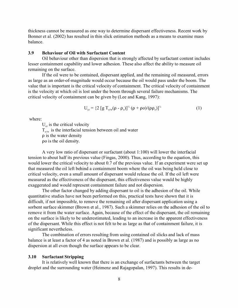
If the oil were to be contained, dispersant applied, and the remaining oil measured, errorsas large as an order-of-magnitude would occur because the oil would pass under the boom. Thevalue that is important is the critical velocity of containment. The critical velocity of containmentis the velocity at which oil is lost under the boom through several failure mechanisms. Thecritical velocity of containment can be given by (Lee and Kang, 1997):
Ucr = {2 [g To/w(D - Do)]½ (D + Do)/(DDo)]
½ (1)
where:Ucr is the critical velocityTo/w is the interfacial tension between oil and waterD is the water densityDo is the oil density.
A very low ratio of dispersant or surfactant (about 1:100) will lower the interfacialtension to about half its previous value (Fingas, 2000). Thus, according to the equation, thiswould lower the critical velocity to about 0.7 of the previous value. If an experiment were set upthat measured the oil left behind a containment boom where the oil was being held close tocritical velocity, even a small amount of dispersant would release the oil. If the oil left weremeasured as the effectiveness of the dispersant, this effectiveness value would be highlyexaggerated and would represent containment failure and not dispersion.
The other factor changed by adding dispersant to oil is the adhesion of the oil. Whilequantitative studies have not been performed on this, practical tests have shown that it isdifficult, if not impossible, to remove the remaining oil after dispersant application using asorbent surface skimmer (Brown et al., 1987). Such a skimmer relies on the adhesion of the oil toremove it from the water surface. Again, because of the effect of the dispersant, the oil remainingon the surface is likely to be underestimated, leading to an increase in the apparent effectivenessof the dispersant. While this effect is not felt to be as large as that of containment failure, it issignificant nevertheless.
The combination of errors resulting from using contained oil slicks and lack of massbalance is at least a factor of 4 as noted in Brown et al. (1987) and is possibly as large as nodispersion at all even though the surface appears to be clear.
3.10 Surfactant StrippingIt is relatively well known that there is an exchange of surfactants between the target
droplet and the surrounding water (Heimenz and Rajagopalan, 1997). This results in de-

9
stabilization of the emulsion. In situations where the water is a large ratio to the dropletconcentration, surfactant is largely lost and destabilization is relatively rapid. In laboratory tests,the ratio of the oil to water then becomes important in simulating the conditions at sea. In theswirling flask test used here, the oil-to-water ratio is 1:1200 which may be somewhatrepresentative of a more open situation. The relationship of the energy, the dilution, and otherfactors in the laboratory test to open water conditions is not well understood at this time.
Chemically dispersed oil has been known to destabilize due to the loss of surfactants tothe water column. Once droplets lose a critical amount of surfactant, they are less likely toremain in the water column. This effect was measured in a study using ASMB and ANS crudeoils and the dispersants Corexit 9500 and Corexit 9527 (Fingas et al., 2002). Resurfacing wasconsistent within each group of tests, static and shaken. The values for those samples shakencontinuously fit an equation of the form, effectiveness = a + b/time. For the static tests, anequation of the form, effectiveness = a + b//time, was the best. A method to generally predictthis fall off in effectiveness with time was developed by correlating all the equations andpreparing a two-level prediction scheme.
Results show that, under all conditions, significant amounts of oil resurface in theswirling flask after the initial dispersion takes place. While mixing has a tendency to retain moreoil in the water column, only about 10% more oil is retained in the water column than if thesystem is static. The relation of this process to what may occur in the sea has not beendetermined, however, resurfacing has been noted in several sea trials. Provision should be madeto track the plume and test for resurfacing.
3.11 Recovering Surface OilSome experimenters have tried to recover surface oil in an attempt to directly determine
effectiveness by presuming that the entire remainder is dispersed. This is incorrect because theloss from the surface includes the amount evaporated, the amount in very thin (often invisible)slicks, the amount that is physically unrecoverable, oil adhered to booms or other surface objects,errors in the amounts of all the oil compartments, and oil that is simply unaccounted for.
Controlled tests in a test tank have shown that the difference between oil accounted for inthe water column and the amount on the surface can vary from 0 to 80% (Brown et al., 1987;Brown and Goodman, 1988). This again represents the typical error of trying to perform asurface-only measurement. Once oil is treated with dispersant, it becomes less adhesive andtherefore much more difficult to recover from the surface using typical skimmers and sorbents.This fact can contribute to the error.
Some experimenters have recovered surface oil (Page et al., 1999, Tissot et al., 2000).While a very good experimental procedure, it should be noted for the reasons described above,that this number is fraught with error and great care must be taken to ensure good recovery aswell as subsequent interpretation of the results.
3.12 Background Levels of HydrocarbonsThe background level of hydrocarbons is important for several reasons, some of which
are noted above. A good background value is needed first to subtract concentration values andsecond to know when to terminate integration of the spill. It is suggested that the sametechniques, along with the grab samples for calibration, be applied in the area before dispersant

10
application and also after, if practical, to determine the range of background values in the area. These values can then be judged for use in correcting the values and for ending integration.
Another problem associated with the background levels is that hydrocarbons will adhereto sample tubes and equipment. This will result in higher than background values at the end of arun through the plume. There is no easy solution to the problem. One of the solutions is toexamine the values and look at where the signal drops off significantly, probably at the end of theplume, and use this value as a ‘corrected’ background. Some experimentation at the scene of themeasurements can be used to define the carry-though of hydrocarbons in the system. It should benoted that, if the carry-through is not corrected for, gross errors could occur in the amount of oil calculated.
3.13 Fluorescence of the DispersantWhile the dispersant mixtures, per se, should not fluoresce, most of them show a
significant signal when placed in a Turner Fluorometer (Lambert et al., 2001a). The reason forthis fluorescence is the reflection of UV and other light into the detection path and the actualfluorescence of small amounts of fluorescent material in the dispersant or picked up through thesystem. Most experimenters have ignored the fluorescence of the dispersant in the past because itwas presumed that there was no contribution. Furthermore, in an actual application orexperiment, the pickup of even a small amount of oil by the dispersant will result in a significantsignal. While this is difficult to correct for, one way is to correct all the readings to accurate GCanalytical results.
3.14 HerdingHerding is the phenomenon that occurs when the oil is pushed aside by the dispersant
(Merlin et al., 1989). This occurs because the spreading pressure of the dispersant can be morethan that of the oil slick, especially when the oil slick is thin. The dispersant must directly contactthe water surface in order to cause herding. This readily occurs with thin oil slicks becauseaerially applied droplets are generally 300 to 1200 :m in size, while the oil slick could easily beas thin as 100 :m (appearing as a thick slick) (Merlin et al., 1989).
There are several problems with herding, the major one being that often little dispersionoccurs if the oil is herded. The larger droplets will land on the surface first and cause herding ifthe conditions are correct and then much of the dispersant that follows in smaller droplets canland directly on the water.
3.15 Heterogeneity of the Slick and PlumeAs slicks are rarely homogeneous in thickness, the dispersant applied may be insufficient
in areas or may break through and cause herding in other areas (Merlin et al., 1989, Payne et al.,1993). Furthermore, slick heterogeneities will result in heterogeneities in the dispersant plume,which will again result in difficulties integrating the plume. Using peak values will result in over-estimating the dispersant effectiveness and vice versa. This difficulty can be mitigated byintegrating very small areas of the sub-surface plume. In tanks, this can be overcome somewhatby continuing circulation for 24 hours and then measuring (Brown et al., 1987).
11
3.16 True Analytical StandardsThere now exist certified laboratories that use certified petroleum hydrocarbon
measurement techniques. These should be used for tank studies. One of the most seriousdifficulties in older field and tank trials occurred when inexperienced staff tried to conductchemical procedures. Analytical methods are complex and cannot be conducted correctly withoutchemists familiar with the exact procedures.
Furthermore, field instrumentation such as fluorometers require calibration using standardprocedures and field samples during the actual trial. These samples must be taken and handled bystandard procedures. Certified standards must be used throughout to ensure good QualityAssurance/Quality Control (QA/QC) procedures.
In this era, it is simply unacceptable not to use certified methods, laboratories, andchemists.
3.17 Weathering of the OilDispersant effectiveness decreases with weathering of the oil. The weathering trend is
characteristic of that oil, but every oil shows this decrease (Fingas et al., 2001). The oil used forany dispersant test should be weathered to an extent that it would represent a realistic situation,e.g., equivalent to about 1 day. The weathering of the oil will also assist in maintaining a morecorrect mass balance.

12
4. How a Test Tank Could be Used to Measure Dispersant EffectivenessIn the first part of this paper, the following 17 factors were noted as being relevant to the
proper measurement of dispersant effectiveness in a tank.1. Mass balance2. Proper controls3. Analytical method4. Differential plume movement5. Time lag and length of time plume followed6. Mathematics of calculation and integration7. Lower and upper limits of analytical methods8. Thickness measurement9. Behaviour of oil with surfactant content10. Surfactant stripping11. Recovering surface oil12. Background levels of hydrocarbons13. Fluorescence of dispersant14. Herding15. Heterogeneity of slick and plume16. True analytical standards17. Weathering of the oil18. Temperature and salinityMost of these factors can be taken into consideration or problems avoided if the testing
follows the extensive studies of the past. In particular, the tank test studies described by Brown etal. (1987) dealt with several of these issues and showed how dispersant effectiveness could bemeasured in a test tank. The calibration of tank hydrodynamics and calculation of mass balanceare also dealt with extensively in Bonner et al. (2002).
The suggested method is that the fresh, unweathered oil be placed in the test tank.Weathering should be allowed to occur for 12 to 24 hours after placement. Containment of theoil should be used only to enhance contact, not as an analytical method. After the oil is placed,dispersant is applied at the desired ratio. Approximately 6 hours after the application, a series offluorometers are run through the tank at depths of about 1 m apart and at various spacings acrossthe cross-section. During the sampling, discrete water samples are taken from the fluorometersand the exact readings of the fluorometer recording (best done electronically) during the time thatsamples are taken. These samples are then correctly preserved and analyzed for TPH. Thecalibration curve for the fluorometer is derived from these measurements. It is important thatsampling, preservation, and analysis be done using certified methods, by certified chemists, andin certified labs.
The 6-hour sampling data are compared to the 24-hour sampling data which are taken inexactly the same manner. The effectiveness is then estimated from integration at the 24-hourmark. The 3-hour sample period is for checking and would be conducted only in the first test ortwo.
After the 24-hour period, the oil on the surface is driven to one corner where it isrecovered with a skimmer for weighing. Elastol can assist in recovering the surfactant-treated oil. A mass balance is then achieved by comparing the oil recovered in the whole tank, the amount

13
estimated on the walls, and the amount in the water column. The oil in the water column is theonly amount dispersed. The mass balance is used to judge the validity of the particular run andnot the effectiveness of a specific dispersant.
The tank filtration system is turned off during the experiment and is turned on only afterthe surface oil is recovered. Only about four experiments can be done before all the water mustbe changed due to the presence of surfactants.
The wave maker is left on for the full 24 hours.The hydrocarbon background is also determined in the same way as the dispersant
concentration and this is done just before the dispersant experiment.This method will overcome difficulties and ensure that the 17 critical factors are taken
into consideration.
4.1 Additional Information on Tank TestingIt is important during any experiment to alter only one variable at a time. Otherwise, the
outcome may be a result of the combination of the inputs, leading to confusion as to what theeffect was of a given variable.
The experiences of Bonner et al. (2002) show that there are major losses of oil in threeareas that historically have not been considered in performing a mass balance. These are adhesionto walls, adhesion to sediments, and formation of invisible slicks. These three losses can accountfor over 50% of the oil loss in certain cases. Methods for the measurement of each of these oillosses were developed and applied. The adhesion to the walls was measured by placing strips ofwall material into the test tank and later removing and quantifying the oil on these strips. It wasnoted that the age and conditions of these strips were important as the more weathered tankwould hold more oil than the newer, unweathered strips.
Bonner et al. (2002) noted that the sediment (even that from the apparently clean tankbottom) must be collected and oil content measured. Oil in thin slicks was measured using asolid-phase extraction disk held by vacuum to retain both the disk and oil adhered to the disk.
Another distinct issue is that of scaling of wave energy (Bonner et al., 2002). Dispersanteffectiveness is largely affected by energy inputs and therefore scaling and control of this in a testtank is an important factor. In the laboratory, energy input to the dispersant/oil mixture can bevery tightly controlled, but in a test tank it could be highly variable and subject to influences suchas winds, etc. Bonner et al. (2002) provide mathematical tests of energy scaling and means toestimate wave reflection, which is another source of variability.
The use of containment while dispersant effectiveness is being measured in a test tankshould be reviewed. There is no doubt that this increases the turbulent energy at the boundarybetween contained and uncontained oil. Since this would not occur at sea or in most laboratorytests, this extra high energy may result in atypical results.

14
5. ReferencesBocard, C., G. Castaing, J. Ducreux, C. Gatellier, J. Croquette and F. Merlin, “Summary ofProtecmar Experiments, The French Dispersant Offshore Trials Program”, Oil and ChemicalPollution, Vol. 3, pp 471-484, 1986/87.
Bonner, J., C. Page and C. Fuller, “Meso-Scale Testing and Development of Test Procedures toMaintain Mass Balance”, Spill Science and Technology, in press, 2002.
Brown, H.M. and R.H. Goodman, “Dispersant Tests in a Wave Basin: Four Years ofExperience”, in Proceedings of the Eleventh Arctic Marine Oilspill Program (AMOP) TechnicalSeminar, Environment Canada, Ottawa, ON, pp 501-514, 1988.
Brown, H.M., R.H. Goodman and G.P. Canevari, “Where Has All the Oil Gone? Dispersed OilDetection in a Wave Basin and at Sea”, in Proceedings of the 1987 International Oil SpillConference, American Petroleum Institute, Washington, DC, pp 307-312, 1987.
Fingas, M.F., “Field Measurement of Effectiveness: Historical Review and Examination ofAnalytical Methods”, in Oil Dispersants: New Ecological Approaches, STP 1018, L.M. Flaherty(ed.), American Society for Testing and Materials, Philadelphia, PA, pp 157-178, 1989.
Fingas, M.F., “Use of Surfactants for Environmental Applications”, in Surfactants:Fundamentals and Applications to the Petroleum Industry, Laurier L. Schramm, (ed.), Chapter12, Cambridge University Press, pp 461-539, 2000.
Fingas, M.F., “A White Paper on Oil Spill Dispersant Field Testing”, Prince William SoundRegional Citizens' Advisory Council (PWSRCAC) Report, Anchorage, AK, 40 p., 2002.
Fingas, M.F., B. Fieldhouse, L. Sigouin, Z. Wang and J. Mullin, “Dispersant EffectivenessTesting: Laboratory Studies of Fresh and Weathered Oils”, in Proceedings of the Twenty-fourthArctic and Marine Oil Spill Program (AMOP) Technical Seminar, Environment Canada, Ottawa,ON, pp 551-556, 2001.
Fingas, M.F., L. Sigouin, Z. Wang and G. Thouin, “Resurfacing of Oil with Time in the SwirlingFlask”, in Proceedings of the Twenty-fifth Arctic and Marine Oil Spill Program (AMOP)Technical Seminar, Environment Canada, Ottawa, ON, pp 773-783, 2002.
Gill, S.D., R.H. Goodman and J. Swiss, “Halifax '83 Sea Trial of Oil Spill DispersantConcentrates”, in Proceedings of the 1985 International Oil Spill Conference, AmericanPetroleum Institute, Washington, DC, pp 479-482, 1985.
Goodman, R.H. and M.F. Fingas, “The Use of Remote Sensing in the Determination ofDispersant Effectiveness”, Spill Technology Newsletter, Vol. 13, No. 3, pp 55-58, 1988.
Heimenz, P.C. and R. Rajagopalan, Principles of Colloid and Surface Chemistry, Marcel Dekker,Inc., New York, NY, 1997.

15
Lambert, P., B. Fieldhouse, Z. Wang, M.F. Fingas, M. Goldthorp, L. Pearson and E. Collazzi,“Preliminary Results from the Laboratory Study of a Flow-Through Fluorometer for MeasuringOil-in-water Levels”, in Proceedings of the Twenty-third Arctic and Marine Oil Spill Program(AMOP) Technical Seminar, Environment Canada, Ottawa, ON, pp 69-98, 2000.
Lambert, P., M. Goldthorp, B. Fieldhouse, Z. Wang, M. Fingas, L. Pearson and E. Collazzi, “AReview of Oil-in-Water Monitoring Techniques”, in Proceedings of the 2001 International OilSpill Conference, American Petroleum Institute, Washington, DC, pp 1375-1380, 2001a.
Lambert, P., B. Fieldhouse, Z. Wang, M. Fingas, M. Goldthorp, L. Pearson and E. Collazzi, “ALaboratory Study of Flow-through Fluorometer for Measuring Oil-in-Water Levels”, inProceedings of the Twenty-fourth Arctic and Marine Oil Spill Program (AMOP) TechnicalSeminar, Environment Canada, Ottawa, ON, pp 23-45, 2001b.
Lee, C.M. and K.H. Kang, “Prediction of Oil Boom Performance in Currents and Waves”,Advanced Fluids Engineering Research Centre, Phang, Korea, 24 p., 1997.
Louchouarn, P., J.S. Bonner, P. Tissot, T.J. McDonald, C. Fuller and C. Page, “QuantitativeDetermination of Oil Films/Slicks from Water Surfaces Using a Modified Solid-phase Extraction(SPE) Sampling Method”, in Proceedings of the Twenty-third Arctic and Marine OilspillProgram (AMOP) Technical Seminar, Environment Canada, Ottawa, ON, pp. 59-68, 2000.
Lunel, T., “Dispersion of a Large Experimental Slick by Aerial Application of Dispersant”, inProceedings of the Seventeenth Arctic and Marine Oilspill Program (AMOP) Technical Seminar,Environment Canada, Ottawa, ON, pp 951-966, 1994a.
Lunel, T., “Field Trials to Determine Quantified Estimates of Dispersant Efficiency at Sea”, inProceedings of the Seventeenth Arctic and Marine Oilspill Program (AMOP) Technical Seminar,Environment Canada, Ottawa, ON, pp 1011-1021, 1994b.
Merlin, F., C. Bocard and G. Castaing, “Optimization of Dispersant Application, Especially byShip”, in Proceedings of the 1989 International Oil Spill Conference, American PetroleumInstitute, Washington, DC, pp. 337-342, 1989.
Page, C., P. Sumner, R. Autenrieth, J. Bonner and T. McDonald, “Materials Balance on aChemically-Dispersed Oil and a Whole Oil Exposed to an Experimental Beach Front”, inProceedings of the Twenty-second Arctic and Marine Oilspill Program (AMOP) TechnicalSeminar, Environment Canada, Ottawa, ON, pp 645-658, 1999.
Payne, J.R., T. Reilly, R.J. Martrano, G.P. Lindblom, M.H. Kennicutt II and J.M. Brooks, “Spillof Opportunity Testing of Dispersant Effectiveness at the Mega Borg Oil Spill”, in Proceedingsof the 1993 International Oil Spill Conference, American Petroleum Institute, Washington, D.C.,pp 791-793, 1993.

16
Swiss, J.J., N. Vanderkooy, S.D. Gill, R.H. Goodman and H.M. Brown, “Beaufort Sea Oil SpillDispersant Trial”, in Proceedings of the Tenth Arctic and Marine Oilspill Program (AMOP)Technical Seminar, Environment Canada, Ottawa, ON, pp 307-328, 1987.
Tissot, P., C. Fuller, P. Louchouarn, J. Bonner, S. Dellamea and D. Bujnoch, “QuantitativeMethod for Surface Oil Measurement and Recovery Based on a New Type of Low ImpactSkimmer”, in Proceedings of the Twenty-third Arctic Marine Oilspill Program (AMOP)Technical Seminar, Environment Canada, Ottawa, ON, pp 353-366, 2000.