documenta
DESCRIPTION
asTRANSCRIPT

RAJASTHAN RAJYA VIDYUT PRASARAN NIGAM LTD. (Regd. Office: Vidyut Bhavan, Janpath, Jyoti Nagar, Jaipur–302005)
SIX WEEK TRAINING REPORT

Page 2 of 71
Report On
“400 kv GSS Heerapura”
Submitted by:
Sadaf Siddiqui
Order No:714
IIIrd year B.Tech
EEE Branch
Maharani Girls Engineering College
Jaipur,RajasthanSummer 2013

Page 3 of 71
ACKNOLEDGEMENT
I am very grateful to Mr. (Executive Engineer) Mrs. (Assistant Engineer) Mr. & Mr. A.P.Vishnu (Assistant Engineer) for his very useful guidance, technical & much advantageous lectures .I would also like to express my sincere thanks towardSLDC Sec t i on , RRVPNL, 400 kv GSS Hee rapu ra , J a ipu r . Fo r t he i r co -ordination & support in problem solving .I am also thankful to Mr. Praveen Khaliya (H.O.D., Electrical & Electronics Engineering) because he encouraged me throughout the practical training and helped to understood correctly.

Page 4 of 71
The objective or main motive of this practical training is to getting a true practical knowledge about the industries, that how their industrial setups are held, how these are protected, and their communication techniques used in industry technologies to be made or used in the environment. T h i s r e p o r t i s p r e s e n t e d o n t h e b a s i s o f p r a c t i c a l t r a i n i n g acquired in “400 KV GSS” RRVPNL,Heerapura, Jaipur. This report is on with relevant diagrams &by their proper description & explanation.400 KV Grid Sub Stations, a high voltage substation receiving electricity with minimum transmission losses and forwarding the step down voltage levels for further distribution to our house holds. A training session out there will help you understand the various devices used in transmission, possible loses, and practical approach of various aspects of transmission and distribution. In spite of all my best efforts some unintentional errors might have eluded, it is requested to abrogated them.

Page 5 of 71
Content
1. Introduction2. Yard equipment at 400 kv GSS3. Power transformer4. Bus bar5. Circuit breaker6. Lightning arrestor7. Wave trap8. Capacitive voltage transformer9. Isolator10. Current transformer11. Earthing of system12. Protective relay13. Other equipment14. Transformer oil and its testing15. Control room16. Battery room17. Transformer repair shop18. Single line diagram19. Conclusion20. References
Page 6 of 71
INTRODUCTIONWhen people talk about the electric power industry, the focus of the conversation is usually on the power generation side of the business or on the utilities. The power generation side examines the extraction of fossil fuels, alternative energy generation, oil spills, carbon emissions, and nuclear power. The utilities side focuses on the customer-oriented delivery side of the business, from electricity bill surcharges to outages in our electricity supply.
A third and often overlooked portion of the power and energy industry is the transmission and distribution space (T&D), an important cluster of industries that include the production of machinery, electric lines and transformers as well as line management systems (such as "smart-grid" technology) that improve efficiency. These are responsible for the actual “delivery” of the electric power—no matter the generation source, be it solar, gas, oil, wind or otherwise—to commercial, private and industrial users in a usable format. This describes the T&D space within the energy economy and then summarizes the challenges yet tremendous growth potential for this cluster of industries given the aging infrastructure and rapid technological advancement of the developing world.
Understanding Key Elements of the T&D Space

Page 7 of 71
The T&D market supplies equipment, services and production systems for energy markets. The initial stage in the process is converting power from a generation source (coal, nuclear, wind, etc.) into a high voltage electrical format that can be transported using the power grid, either overhead or underground. This “transformation” occurs very close to the source of the power generation. The second stage occurs when this high-voltage power is “stepped-down” by the use of switching gears and then controlled by using circuit breakers and arresters to protect against surges. This medium voltage electrical power can then be safely distributed to urban or populated areas. The final stage involves stepping the power down to useable voltage for the commercial or residential customer (see Figure 1).
Figure 1: Transmission and Distribution Grid Structure within the Power Industry
Page 8 of 71
Figure-1
(Source: U.S. Department of Energy. "Benefits of Using Mobile Transformers and Mobile Substations for Rapidly Restoring Electric Service: A Report to the United States Congress Pursuant to Section 1816 of the Energy Policy Act of 2005." 2006.)
In short, while power generation relates to the installed capacity to produce energy from an organic or natural resource, the T&D space involves the follow up “post-power generation production” as systems and grids are put in place to transport this power to end users. While the T&D space does not perfectly follow typical industrial classification

Page 9 of 71
systems, its primary industries can be loosely distinguished from power generation.
Despite its name, only part of the electric power distribution industry belongs to the T&D space and most of it to the generation and utilities group since it includes a substantial number of traditional utility businesses that focus exclusively on the “sale of electricity via power distribution systems operated by others.”
The T&D space is estimated to have a market share of over $50 billion globally and can be divided into four main segments, according to the organizational structure used by AREVA.
Products: Manufacture of high and medium voltage power and distribution transformers. The drivers for this market are the aging T&D infrastructure, load growth from sprawl, deregulation and general industrial growth.
Services: Support for the products and systems sold throughout its lifecycle, usually contracts for repair and maintenance. The drivers for this segment are aging infrastructure, preventative maintenance and general outsourcing.
Systems: Research and development of turnkey substations, electronics for direct current substations and systems to increase grid capacity and quality. This fast growing market is primarily driven by an increased need for power electronics, network efficiency, reliability, and new sources for renewable energy.

Page 10 of 71
Automation: Products to detect failures, ruptures and general protection arenas. This may also include systems for substation and energy management or for remote management for the power grid.
Sub-Station
Electric power is generated, transmitted and distributed in the form of alternating current. The electric power produced at the power stations is delivered to the consumers through a large network of transmission & distribution.
The transmission network is inevitable long and high power lines are necessary to maintain a huge block of power from source of generation to the load centers to inter connected. Power house for increased reliability of supply greater.
The assembly of apparatus used to change some characteristics (e.g. voltage, ac to dc, frequency, power factor etc.) of electric supply keeping the power constant is called a sub-station.
Depending on the constructional feature, the high voltage sub-stations may be further subdivided:
a) Outdoor substation.
b) Indoor substation.
c) Basement or Underground substation.
Page 11 of 71
Figure-2
400 KV G.S.S. HEERAPURA
1) It is an outdoor type substation.
2) It is primary as well as distribution substation.
3) One and half breaker scheme is applied.
FEEDERS
1) One feeder of 220kv KTPS1
2) One feeder of 400kv Bassi-I
3) One feeder of 220kv Kota(S)III
4) One feeder of 400kv Bassi-II
5) One feeder of 400kv Merta
6) One feeder of 220kv Sanganer

Page 12 of 71
At this substation following feeders are established:
TIE FEEDERS.
RADIAL FEEDERS.
TIE FEEDERS:
There are feeders as follows.
1.220 KV KOTA-JAIPUR 1st & 2nd
2. Inter- state 220KV KOTA –DELHI
1. Tie from 220 KV Heerapura.
2. 220KV KTPS first & second.
3. Inter- state 400 kV Bassi- Heerapura- I & II
RADIAL FEEDERS
220 KV JAIPUR –KOTA 1st & 2nd feeders

Page 13 of 71
YARD EQUIPMENT AT 400 KV GSS
1. Power Transformers
2. Bus Bar
3. Circuit Breakers
4. Isolators
5. Current Transformers
6. Capacitor Voltage Transformers (CVT) /
Potential Transformers (PT)
7. Insulators
8. Lightning Arresters
9. Wave Traps
10. Line Traps
11. Capacitor Banks
12. Earthing
13. Battery Room
14. Control & Relay Panels
15. Control Room
POWER TRANSFORMER

Page 14 of 71
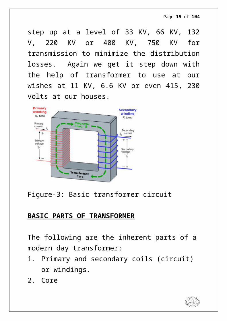
The transformer is a static apparatus, which receives power/energy at it, one circuit and transmits it to other circuit without changing the frequency. With this basic conception we can use the voltages at our desired level while utilizing the power. As, the voltage used to generate at modern power houses at 11 KV or so and afterwards we get it step up at a level of 33 KV, 66 KV, 132 V, 220 KV or 400 KV, 750 KV for transmission to minimize the distribution losses. Again we get it step down with the help of transformer to use at our wishes at 11 KV, 6.6 KV or even 415, 230 volts at our houses.
Figure-3: Basic transformer circuit
BASIC PARTS OF TRANSFORMER
The following are the inherent parts of a modern day transformer:1. Primary and secondary coils (circuit) or windings.2. Core3. Main Tank

Page 15 of 71
4. Conservator5. Breather6. Radiator7. Buchholz relay8. Explosive vent 9. Bushings (HT & LT) (Primary or secondary)10. Cooling fans11. Tap changer (on load and off load)12. NGR (Neutral Grounding Resistance) to minimize the
earth fault current
GAS OPERATED RELAY:-The relay is located in the pipe between the main tank and conservator. In case of fault such as insulation was creating impulse failures fall of oil level produces gases. This rises and accumulated in the upper part of the housing consequently the oil level falls down and the float sinks thereby tilling the mercury switch. The conducts are closed and alarm circuit is energized. Bachholz protection is always used in conjunction with some other forms of electricity operated protective gears as it can unity operate for truly internal transformer faults and does not respond to external bushings or cable faults.
SILICA GEL BREATHER:-A silica gel breather is employed as a measurement of preveusing moisture in gress. It is connected to the conservator tank which is filled to transformer to allow for changes in volume due to temperature variation.
FILTER: - Filter is intended for prolonging like water acid etc from oil. . TRANSFORMER OIL:-

Page 16 of 71
In transformer, the insulating oil provides an insulating medium as well as a heat transferring medium that carry away heat produced in the winding and iron core.The life of the transformer depends chiefly upon the quality of the insulating oil. So high quality insulating oil are used. It should meet the following requirements:-• It should be provide good transfer of heat. • It should provide high electric strength. • It should have low velocity. • Flash point of the oil must be high. • Also fire point should be high.
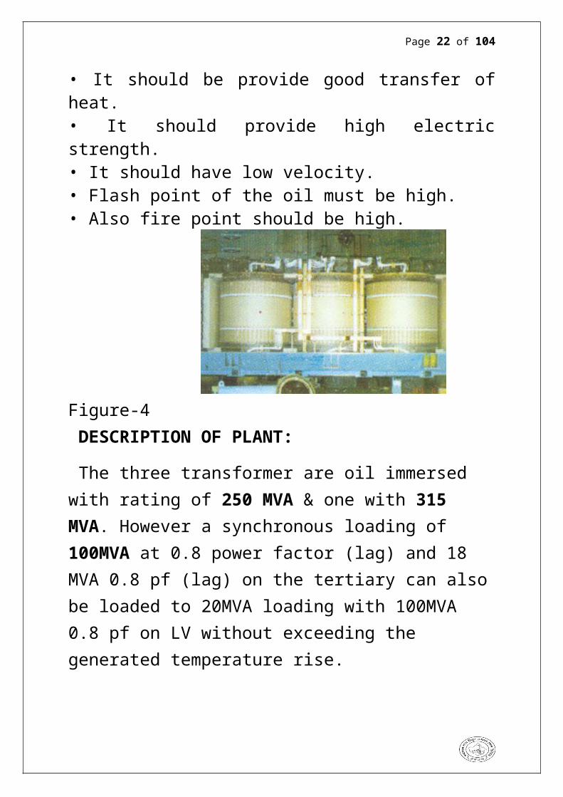
Figure-4 DESCRIPTION OF PLANT:
The three transformer are oil immersed with rating of 250 MVA & one with 315 MVA. However a synchronous loading of 100MVA at 0.8 power factor (lag) and 18 MVA 0.8 pf (lag) on the tertiary can also be loaded to 20MVA loading with 100MVA 0.8 pf on LV without exceeding the generated temperature rise.
The transformer is also provided with a separate bank of radiation, fans, and associated control equipments. The control equipments are housed in a tank mounted miscalling.

Page 17 of 71
Figure- 5
RATING DATAS.
Type of cooling:
ONAN / ONAF/ ODAF
Capacity (MVA ):
HV: 189 / 252 / 315
IV: 189 / 252 / 315
LV: 63 / 84 / 105
VOLTS
HV: 400 KV
IV: 220 KV
LV: 33 KV
LINE AMPERES
HV: 273 / 364 / 455

Page 18 of 71
IV: 497 / 662 / 828
LV: 1104 / 1471 /1839
IMPEDANCE VOLTAGE
HV to IV 12.65% on 315 MVA Base
HV to LV 39.16 % on 315MVA Base
IV to LV 26.66 % on 315 MVA Base
YEAR OF MANUFACTURE: 1985
NUMBER OF PHASES:
Three HV, LV, IV
FREQUENCY IN Hz :
50 Hz
Specifications:
Mass of Core & Windings: 1,32,000 kgMass of Oil: 65,150 kg
Total weight: 261,200 kg
Oil in tank: 73,200 kg
Oil in radiator: 8400 kg
Oil in tap changer: 83,850 kg
Transportation mass: 168,000 kg
Unmaking height: 7760 mm Unmaking mass 18000 Kg
Page 19 of 71
Guaranteed maximum temperature rise of:
Oil 45ºC
Winding 50ºC
COOLING FANS:
Rating: 2000 m3 of air per minute.
Type: 915 mm dial GEC (India) make.
Numbers per transformer: two
Fan motor: direct on line starts weather proof.
Squirrel cage IM 1400 W 400/440
Volt 3- , 50 Hz 720 rpm
PUMPS:
Rating: 1818 liters per minute.
Type: a landless A to 8c sentiment.
Number of pump per transformer: one working, one standby.
Pump motor: direct on line starts weather proof.
Squirrel cage IM

Page 20 of 71
BUS BARS
Bus Bars are the common electrical component through which
a large no. of feeders operating at same voltage have to be
connected.
If the bus bars are of rigid type (Aluminum types) the structure heights are low and minimum clearance is required. While in case of strain type of bus bars suitable ACSR conductors are strung / tensioned by tension insulator discs according to system voltages. In the widely used strain type bus bars stringing tension is about 500 - 900 kg depending upon the size of conductor used.
Here proper clearance would be achieved only if require tension is achieved. Loose bus bars would effect the clearances when it swings while over tensioning may damage insulators. Clamps or even effect the supporting structures in low temperature conditions.The clamping should be proper, as loose clamp would spark under in full load condition damaging the bus bars itself.
BUS BAR ARRANGEMENT MAY BE OF
FOLLOWING TYPES WHICH ARE BEING ADOPTED
BY R.R.V.P.N.L
The commonly used bus bar schemes at Sub Stations are:
Page 21 of 71
a) Single bus bar.b) Main and Auxiliary bus bar.c) Double bus bar.d) Double Main and Auxiliary bus bare) One and a half breaker scheme.
SINGLE BUS BAR ARRANGEMENT:
This is the simplest switching scheme in which each circuit is provided with one circuit breaker. This arrangement offers little security against bus bar faults and no switching flexibility resulting into quite extensive outages of bus bar and frequent maintenance of bus bar isolator(s). The entire Sub Station is lost in case of a fault on the bus bar or on any bus bar isolator and also in case of maintenance of the bus bar. Another disadvantage of this switching scheme is that in case of maintenance of circuit breaker, the associated feeder has also to be shutdown.
Figure- 6
Page 22 of 71
MAIN AND AUXILIARY BUS ARRANGEMENT:This is technically a single bus bar arrangement with an additional bus bar called “Auxiliary bus” energized from main bus bars through a bus coupler circuit, i.e., for ‘n’ number of circuits, it employs ‘n + 1’ circuit breakers. Each circuit is connected to the main bus bar through a circuit breaker with isolators on both sides and can be connected to the auxiliary bus bar through an isolator. The additional provision of bus coupler circuit (Auxiliary bus) facilitates taking out one circuit breaker at a time for routine overhaul and maintenance without de – energizing the circuit controlled by that breaker as that circuit then gets energized through bus coupler breaker. As in the case of single bus arrangement, this scheme also suffers from the disadvantagesthat in the event of a fault on the main bus bar or the associated isolator, the entire substation is lost. This bus arrangement has been extensively used in 132 kV Sub Stations. Figure- 7

Page 23 of 71
DOUBLE BUS BAR ARRANGEMENT: In this scheme, a double bus bar arrangement is provided. Each circuit can be connected to either one of these bus bars through respective bus bar isolator. Bus coupler breaker is also provided so that the circuits can be switched on from one bus to the other on load. Thisscheme suffers from the disadvantage that when any circuit breaker is taken out for maintenance, the associated feeder has to be shutdown.This Bus bar arrangement was generally used in earlier 220 kV sub stations.Figure 8

Page 24 of 71
DOUBLE MAIN AND AUXILIARY BUS BAR ARRANGEMENT:The limitation of double bus bar scheme can be overcome by using additional Auxiliary bus, bus coupler breaker and Auxiliary bus isolators. The feeder is transferred to the
Auxiliary bus during maintenance of its controlling circuit breaker without affecting the other circuits.
This Bus bar arrangement is generally used nowadays in 220 kV sub stations. Figure 9

Page 25 of 71
ONE AND A HALF BREAKER ARRANGEMENT:In this scheme, three circuit breakers are used for controlling two circuits which are connected between two bus bars. Normally, both the bus bars are in service.A fault on any one of the bus bars is cleared by opening of the associated circuit breakers connected to the faulty bus bar without affecting continuity of supply. Similarly, any circuit breaker can be taken out for maintenance without causing interruption. Load transfer is achieved through the breakers and, therefore, the operation is simple. However, protective relaying is somewhat more involved as the central (tie) breaker has to be responsive to troubles on either feeder in the correct sequence. Besides, each element of the bay has to be rated for carrying the currents of two feeders to meet the requirement of various switching operations which increases the cost. The breaker and a half scheme is best for those substations which handle large quantities of power and where the orientation of out going feeders is in opposite directions. This scheme has been used in the 400 kV substations.

Page 26 of 71
Figure10

Page 27 of 71
CIRCUIT BREAKERS
Thus circuit breakers are used for switching & protection of various parts of power system. Circuit breaker is a piece of equipment, which can
1) Make or break a circuit either manually or automatically under normal condition.
2) Break a circuit automatically under fault condition3) Make a circuit either manually or by remote control
under fault conditions.
OPERATING PRINCIPLES
A C.B. consists of fixed and moving contacts called electrodes. Under normal operating conditions, these contacts remain closed and will not open automatically until and unless the system becomes faulty. When a fault occurs on any part of the system, the trip coils of the circuit breaker get energised and the moving contacts are pulled apart, thereby opening the circuit.
When the contacts of the C.B. are seperated under fault conditions, an arc is struck between them. The current is thus able to continue until the discharge ceaeses. The production of arc not only delays the current interruption process but it also generates enormous heat which may cause damage to the system or to the C.B.
It is thus necessary to extinguish the arc within the shortest possible time so that the heat generated by it may not reach a dangerous value.

Page 28 of 71
ARC PHENOMENON
When a short circuit occurs, a heavy current flows through the contacts of the C.B. before they are opened by the protective system. At the instant when the contacts begin to separate, the contact area decreases rapidly and large fault current causes increased current density and hence rise in temperature. The heat produced in the medium between contacts is sufficient to ionize the arc or vaporize and ionize the oil. The ionized air or vapour acts as conductor and an arc is set between the contacts. The potential difference between the contacts is quite small and is sufficient to maintain the arc. the arc provides a low resistance path and as a result the current in the circuit remains uninterrupted so long as the arc persists.
During the arcing period the current flowing between the contacts depends on the arc resistance. The greater the arc resistance, the smaller the current that flows between the contacts. The arc resistance depends upon:
(i) Degree of ionization.(ii) Length of arc.(iii) Cross section of arc.
CLASSIFICATION OF THE CIRCUIT BREAKERS:
There are several ways of classifying the circuit breakers. However, the most general way of classification is on the basis of medium used for arc extinction. The medium used for arc extinction is usually oil, air, sulphur hexafluoride (SF6) or vacuum.

Page 29 of 71
Accordingly, circuit breakers may be classified into:
They are generally classified on the basis of the medium used for arc elimination
(i) Oil circuit breakers, which employ some insulating oil for arc extinction.
(ii) Air-blast circuit breakers in which high pressure air blast is used for extinguishing the arc.
(iii) Sulphur hexa fluroide C.B. in which SF6 gas is used for arc extinction.
(iv) Vacuum C.B. in which vacuum is used for arc extinction.
SULPHUR HEXAFLOURIDE (SF6) CIRCUIT BREAKER
In such breakers, sulphur hexaflouride (SF6) gas is used as the arc quenching medium. The sf6 is an electro-negative gas and has a strong tendency to absorb free electrons. The SF6 circuit breakers have been found to be very effective for high power and high voltage service.
CONSTRUCTION
The cylindrical large size steel tanks are mounted horizontally parallel to each other. Each tank consists of SF6 under pressure. The interruption is of multi break type & is placed along the axis of each tank. The interruption assembly is supported inside the tank by the vertical bushing, which are mounted near the end of each tank. Gas at high pressure is supplied to the interrupter from a gas reservoir.

Page 30 of 71
The bushing are also insulated with SF6 the conductor is in the from of copper tube supported at both end by porcelain shields. SF6 gas is supplied from the high pressure tanks. Shields are provided with gasket seals to eliminate leakage of gas from beginnings.
Figure 11
WORKING

Page 31 of 71
In the closed position of the breaker the contacts remain surrounded by SF6 gas at a pressure of about 2.8 kg/sq cm. When the breaker operates, the moving contact is pulled apart and an arc is struck between the contacts. The movement of the moving contact is synchronised with the opening of a valve which permits SF6 gas at 14kg/sq cm pressure from the reservoir to the arc interruption chamber. the high pressure flow of SF6 rapidly absorbs the free electrons in the arc path to form immobile negative ions which are ineffective as charge carriers. The result is that the medium between the contacts quickly builds up high dielectric strength and causes the extinction of the arc. After the breaker operation the valve is closed by the action of a set of springs.
400 KV SF6 C.B. [RATINGS]: -
Manufacture: BHEL Hyderabad.
Type: 3AT3
Rated voltage: Normally 420 KV, maximum 440 KV.
Rated frequency: 50 HZ.
Rated power frequency: voltage: 520 /610 KVp
Rated Impulse withstand voltage:
Lightning: 1425KV
Switching: 1050KV
Rated normal current: 2000 A
Normal current rating:-
At 50 c ambient: 2240Amps

Page 32 of 71
At 40 c ambient: 2500Amps
Short time current rating: 40 KA for 3 sec.
Rated operating duty: 0 to 0.3 sec. c-0-3min-mb.
Rated short circuit duration: 1 sec.
BREAKING CAPACITY [BASED ON SPECIFIED DUTY CYCLE]:
(a) Capacity at rated voltage: 29000MVA [440KV].
(b) Symmetry current: 40 KA.
(c) Asymmetry current: 51.4KA.
Making capacity: 100KA [peak]
Rated pressure of hydraulic operating (gauge): 250-350bar.
Rated pressure of SF6 gas at degree: 7.5bars.
Weight of complete breaker: 11700 Kg.
Weight of SF6 gas: 76.5Kg.
Rated trip coil voltage: 220 V. AC.
Rated closing voltage: 220 V. DC.
First poll to clear factor: 1.3
ADVANTAGES OF SF6 CIRCUIT BREAKER:
1. Due to the superior arc quenching property of SF6, such circuit breakers have very short arching time.
2. Since the dielectric strength of SF6 gas is 2 to 3 times that of air, such breakers can interrupt much larger currents.
3. The SF6 circuit breakers gives noiseless operation due to its closed gas circuit and no exhaust to the atmosphere unlike the air blast circuit breaker.

Page 33 of 71
4. The closest gas enclosure keeps the interior dry so that there is no moisture problem.
5. There is on risk of fire in such breakers because SF6 gas is not inflammable. There are no carbon deposits so that tracking and insulation problems are eliminated.
6. The SF6 breakers have low maintenance cost, light foundation requirement and minimum auxiliary equipment.
7. Since SF6 breakers are totally enclosed and sealed from atmosphere they are particularly suitable where explosion hazard exists e.g., coal mines.
DEMERITS OF SF6 CIRCUIT BREKER:
1. Sealing problems arise due to the type of the construction used.
2. The presence of moisture in the system is very dangerous to SF6
3. circuit breaker.4. Arced Sf6 gas is poisonous & should not be let out.5. The double pressure SF6 CB is cost liner due to complex
gas system.6. 5. The internal parts should be cleaned thoroughly during
periodic maintenance under clean dry environment.7. Dust of Teflon & sulfide should be removed.8. Special facilities are needed for transporting the gas.
APPLICATIONS
SF6 C.B. have been developed for voltages 115 KV to 230 KV, power ratings 10 MVA to 20 MVA and interrupting time less than 3 cycles.

Page 34 of 71
S.NO I.E. MAKE TYPE VOLTAGE CURRENT STC SF6/HYD
1 552A 3AT3 3AT3 420/520 2000A 40KA/S 7.5/350
2 552T DO DO DO DO DO DO
3 552B MG FAR2 DO 3150A DO 7/300
4 452T NGEF S2M420 420/610/1425 2000A DO 8/35
5 252A BHEL 3AT3 420/520/1050 DO DO 7.5/350
6 252B ABB EL(V) 420/1050 3150 40KA/3S 7/31.5
Figure-12 ( 400 kV SF6 live tank circuit breakers)
LIGHTENING ARRESTORS

Page 35 of 71
An electric discharge between cloud and earth, between cloud and the charge centers of the same cloud is known as lightening.
The earthing screens and the ground wires can well protect the electrical system against direct lightening strokes but they fail to provide protection against travelling waves which may reach the terminal apparatus. The lightening arrestors or the surge diverters provide protections against such surges.
THYRITE TYPE:
Ground wire run over the tower provides an adequate protection against lighting and reduce the induced electrostatic or electromagnetic voltage but such a shield is inadequate to protect any traveling wave, which reaches the terminal of the electrical equipment, and such wave can cause the following damage.
1 the high peak of the surge may cause a flashover in the internal wiring thus it may spoil the insulation of the winding .
2 the steep wave front may cause internal flash over between their turns of transformer.
3 The stop wave front resulting into resonance and high voltage may cause internal or external flashover causing building up the oscillator is the electrical operation.

Page 36 of 71
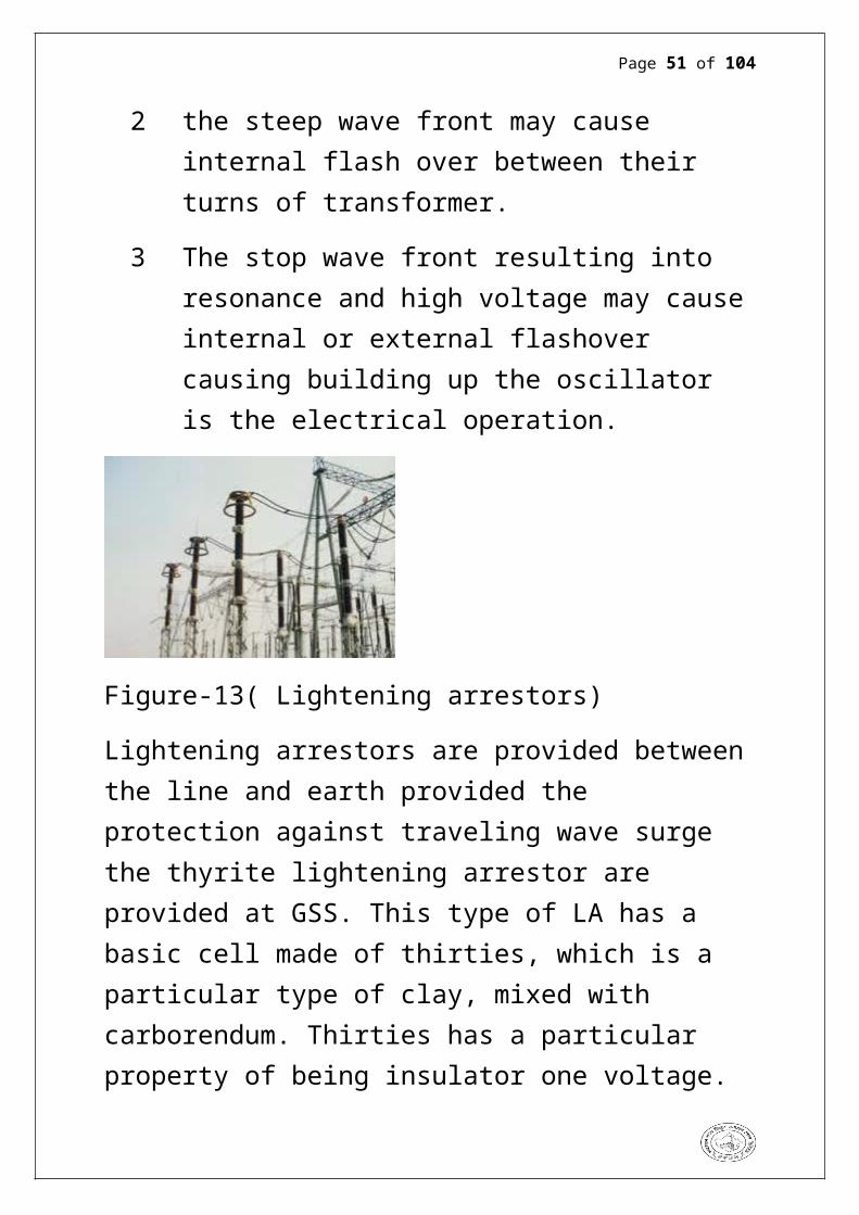
Figure-13( Lightening arrestors)
Lightening arrestors are provided between the line and earth provided the protection against traveling wave surge the thyrite lightening arrestor are provided at GSS. This type of LA has a basic cell made of thirties, which is a particular type of clay, mixed with carborendum. Thirties has a particular property of being insulator one voltage.
At high voltage It will behave like a conducting material the electrical resistance of thyrite depends upon the voltage each time the voltage is made twice the resistance decrease in such a manner as to allow an increased current of 12.5 times the change in current is independent of rate of application voltage and its instantaneous value.
The above law is followed by this material without any limit on the voltage increase and after the surge has passed the thyrite againretain its original property
A standard cell is rated for 1KV and is formed into a disc, which is sprayed on both the sides of to give good contact with each disc. The dimensions of the discs are stacked i.e. 16

Page 37 of 71
cm in diameter and 17.5 cm thick these discs are stacked one upon each other and they are further placed in to a porcelien container with a suitable arrangement of gap between them.
These gaps serves as the purpose of preventing any current flow during normal operating voltage in case of any transients the gap are punctured. The Thyrite type arrestor will discharge several thousands ampere without the slightest tendency of flashover on the edges of most important of the advance is that there is absolutely no time lag in its performance.
400KV LIGHTNENIG ARRESTOR
manufacture: English electric company
Type:LSM
Year:201
no of phases: one
rated voltage: 360 KV
nominal discharge current (8×20µs) 10KA
high current impulse(4×110 µs ) 100KA
long duration rating(200 µs) 500KA
Sno Ie Make Type Current Voltage
1 Bassi1 Wsi Cpl 10KA 360KV
2 bassi2 Elpro Alugard2 10KA 360KV

Page 38 of 71
3 ILT1 Elpro Alugard2 10KA 360KV
4 ILT2 Elpro Alugard2 10KA 360KVh
5 ILT3 WSI CDV303 10KA 398KV
6 ILT4 WSI CDV03 10KA 398KV

Page 39 of 71
WAVE TRAP
Line trap also is known as Wave trap. It is used to trap the communication signals & send PLCC room through CVT. Rejection filters are known as the line traps consisting of a parallel resonant circuit ( L and C in parallel) tuned to the carrier frequency are connected in series at each and of the protected line such a circuit offer high impedance to the flow of carrier frequency current thus preventing the dissipation. The carrier current used for PLC Communication have to be prevented from entering the power equipments such as attenuation or even complete loss of communication signals. For this purpose wave trap or line trap are used between transmission line and power station equipment to- Avoid carrier power dissipation in the power plant reduce cross talks with other PLC Circuits connected to the same power station.Ensure proper operating conditions and signal levels at the PLC transmit receive equipment irrespective of switching conditions of the power circuit and equipments in the
stations.
Figure-14(Wave Trap)

Page 40 of 71
CAPACITIVE VOLTAGE TRANSFORMERS (CVT)
Capacitive voltage transformers are special kind of power transformers using capacitors to step down the voltage.
DESCRIPTION:
The capacitive voltage transformer comprises of a capacitor divider with its associated electromagnetic unit. The divider provides an accurate proportioned voltage, while the magnetic unit transforms this voltage, in both magnitude and phase to convenient levels suitable for measuring, metering, protection etc. all WSI capacitor units has metallic bellows to compensate the volumetric expansion of oil inside. The porcelain in multi unit stack, all the potential points are electrically tied and suitably shielded to overcome the effect of corona RIV etc. Capacitive voltage transformers are available for system voltages of 33 KV to 420KV.
Figure-15

Page 41 of 71
APPLICATION:
1. Capacitive voltage transformers can be effectively as potential sources for measuring ,metering, protection, carrier communication and other vital functions of an electrical network.
2. CVT are constructed in single or multi unit porcelain housing with there associated magnetic units. For EHV systemcuts are always supplied in multi unit construction.
3. In case of EHV cuts the multi unit system has many advantage easy to transport and storing, convenience in handling.
RATING OF CVT
Voltage: 22/sqrt 3 KV
Total o/p:500MVA
Operating voltage: 400/sqrt 3 max.
Voltage factor: 1.5/30 sec.
Test voltage: 630 KV for 1 min
Impulse withstands voltage: 1.2/ 50 s. 1425KV max.
Frequency : 50Hz
High frequency capacitance: 4400pF
Primary capacitance: 4657pF
Secondary capacitance: 80000 pF

Page 42 of 71
S no
Ie Make Ratio Burden Class Sec cap
1 Bassi Wsi/cve/420
/1425
400 200,200,
100
3p,3p,0.5
80000pf
2 Bassi 2
Wsi/cve/420
/1425
400 200,200,
100
3p,3p,0.5
80000pf
3 Bus 1
Wsi/cve/420
/1425
400 200,200,
100
3p,3p,0.5
80000pf
4 Bus 2
Wsi/cve/420
/1425
400 200,200,
100
3p,3p,0.5
80000pf

Page 43 of 71
ISOLATORS
Isolators which are also called disconnect switches or air break switches after the assembly as per drawings on the leveled structures the adjustment of connecting pipes, moving and fixed contacts is done so that all the three phase of the isolator close and open simultaneously and there is a full surface contact between moving and fixed contacts. Such switches are generally used on both sides of equipment in order that repairs and replacement of the equipment can be made without any danger. They should never be opened until the equipment in the same circuit has been turned off and should always be closed before the equipment is turned on.
The adjustment of the tendon pipes leveling of post insulator, stop holts in the fixed contacts etc. is done for smooth operation of insulator. Following type of insulator are being used in R.S.E.B-a) Isolator without earth blades.b) Isolator with earth blade.c) Tendon isolator.
Isolators are file with earthing blades as an integral part of it. They may be isolators with single ear thing blades or two earthling blades on either side of it. The isolators used at 220 KV GSS,Bharatpur have single earthing blades either side of it.They must only be opened or closed when current is zero. Isolators are classified into following categories.1. Bus isolator

Page 44 of 71
2. Line isolator 3. Transformer isolating switch
Figure-16 (400 kv isolator)
SPECIFICATIONS (air break isolator):-

Page 45 of 71
SPECMO CC-141036Type MAIN/ MGBVoltage 420 KVRated AMPS 2000 AShort Time AMPS 40 KA/SImpulse Voltage 1425 KVDC Voltage 220 VAuxiliary Voltage 220 VDCMech Term Load 160 KGMotor Voltage 415 VACType RC-500MCR

Page 46 of 71
INSULATORS
The insulators for the overhead lines provide insulation to the power conductors from the ground so that currents from conductors do not flow to earth through supports. The insulators are connected to the cross arm of supporting structure and the power conductors passes through the clamp of the insulator. The insulators provide necessary insulation between line conductors and supports and thus prevent any leakage current from conductors to earth. In general, the insulators should have the following desirable properties:
1. High mechanical strength in order to withstand conductor load, wind load etc.
2. High electrical resistance of insulator material in order to avoid leakage currents to earth.
3. High relative permittivity of insulator material in order that dielectric strength is high.
4. The insulator material should be non porous, free from impurities and cracks otherwise the permitivity will be lowered.
5. High ratio of puncture strength to flash over.
These insulators are generally made of glazed porcelain or toughened glass. Poly come type insulators [solid core] are also being supplied in place of hast insulators if available indigenously. The design of the insulator is such that the stress due to contraction and expansion in any part of the

Page 47 of 71
insulator does not lead to any defect. It is desirable not to allow porcelain to come in direct contact with a hard metal screw thread.
TYPES OF INSULATORS:
There are three types of insulators used for overhead lines:
1. Pin type- pin type insulator consists of a single or multiple shells adapted to be mounted on a spindle to be fixed to the cross arm of the supporting structure.
When the upper most shell is wet due to rain the lower shells are dry and provide sufficient leakage resistance. These are used for transmission and distribution of electric power at voltage up to voltage 33KV. Beyond operating voltage of 33KV the pin type insulators thus become too bulky and hence uneconomical.
Figure-17 2. Suspension type- suspension type insulators consist of a
number of porcelain disc connected in series by metal

Page 48 of 71
links in the form of a string. Its working voltage is 66KV. Each disc is designed for low voltage for 11KV.
Figure-183. Strain insulator- the strain insulators are exactly identical
in shape with the suspension insulators. These strings are placed in the horizontal plane rather than the vertical plane. These insulators are used where line is subjected to greater tension. For low voltage lines (<11kV) shackle insulators are used as strain insulator.
Figure-19

Page 49 of 71
CURRENT TRANSFORMER
These transformers are used with low range ammeter to measure currents in high voltage alternating current circuits where it is not practicable to connect instruments and meters directly to lines. In addition to insulating the instrument from the high voltage line, they step down the current in the known ratio. The current (or series) transformers has a primary coil of 1 or more turns of thick wires connected in series with the line whose current is to be measured. The secondary consist of a large number of turns of fine wire and is connected across the ammeter terminals (usually of 5 amp bracket should be removed or 1 amp range)
Figure-20

Page 50 of 71
Current transformers are used extensively for measuring current and monitoring the operation of the power grid. Along with voltage leads, revenue-grade CTs drive the electrical utility's watt-hour meter on virtually every building with three-phase service and single-phase services greater than 200 amps.The CT is typically described by its current ratio from primary to secondary. Often, multiple CTs are installed as a "stack" for various uses. For example, protection devices and revenue metering may use separate CTs to provide isolation between metering and protection circuits, and allows current transformers and different characteristics (accuracy, overload performance) to be used for the devices.The accuracy of a CT is directly related to a number of factors including:
Burden Burden class/saturation class Rating factor Load External electromagnetic fields Temperature and Physical configuration. The selected tap, for multi-ratio CTs
Page 51 of 71
EARTHING OF THE SYSTEM:The provision of an earthling system for an electric system is necessary by the following reason.
1 In the event of over voltage on the system due to lightening discharge or other system fault. These parts of equipment, which are normally dead, as for as voltage, are concerned do not attain dangerously high potential.
2 In a three phase, circuit the neutral of the system is earthed in order to stabilize the potential of circuit with respect to earth.
The resistance of earthling system is depending on 1 Shape and material of earth electrode used.2 Depth in the soil3 Specific resistance of soil surrounding in the neighborhood
of system electrodes.PROCEDURE OF EARTHING:Technical consideration the current carrying path should have enough capacity to deal with more faults current. The resistance of earth and current path should be low enough to prevent voltage rise between earth and neutral. The earth electrode must be driven into the ground to a sufficient depth to as to obtain lower value of earth resistance. To sufficient lowered earth resistance a number of electrodes are inserted in the earth to a depth they are connected together to form a mesh. The resistance of earth should be for the mesh in generally inserted in the earth at 0.5m depths the several point of mesh then connected to earth electrode or ground conduction. The earth electrode is metal plate copper is used for earth plate.

Page 52 of 71
Neutral Earthing:
Neutral earthing of power transformer all power system operates with grounded neutral. Grounding of neutral offers several advantages the neutral point of generator transformer is connected to earth directly or through a reactance in some cases the neutral points is earthed through an adjustable reactor of reactance matched with the line. The earthling is one of the most important feature of system design for switchgear protection neutral grounding is important because:
1 The earth fault protection is based on the method of neutral earthling.
2 The neutral earthling is associated switchgear.3 The neutral earthling is provided for the purpose of
protection arcing grounds unbalanced voltages with respect to protection from lightening and for improvement of system.

Page 53 of 71
PROTECTIVE RELAYS
A Protective relay is a device that detects the fault and initiates the operation of the circuit breaker to isolate the defective element from the rest of the system.
The relays detect the abnormal condition in the electrical circuits by constantly measuring the electrical quantities i.e. voltage, current, frequency, phase angle which are different under normal and fault conditions. Having detected the fault, the relay operates to close the trip circuit of the breaker, which results in opening of the breaker and disconnection of the faulty circuit.
Relay circuit connections can be divided in three parts:1.) Primary winding of a C.T. that is connected in series with the line to be protected.2.) Secondary winding of C.T. and the relay operating coil.3.)Third part is the tripping circuit, which may be either a.c. or d.c. . It consists of a source of a supply, the trip coil of a circuit breaker and the relays stationary contacts.

Page 54 of 71
When a short circuit occurs at point F on the transmission line the current increases to enormous value. This results in a heavy current flow through the relay coil, causing the relay to operate by closing its contacts. This in turn closes the trip circuit of the breaker, making the C.B. open and isolating the family section from the rest of the system. In this way, the relay ensures the safety of the circuit equipment from damage and normal working of the healthy portion of the system.
Figure-21Basic qualities that a protective relay must possess are:
1.) Selectivity

Page 55 of 71
2.) Speed3.) Sensitivity4.) Reliability5.) Simplicity6.) EconomyDIFFERENTIAL RELAYSA differential relay is one that operates when the phasor difference of two or more similar electrical quantities exceeds a predetermined value.Thus the current differential relay is one that compares the current entering and current leaving the section. Under normal operating conditions, the two currents are equal but as soon as fault occurs, this condition is no longer applied.The difference between the incoming and outgoing currents is arranged to flow through the operating coil of the relay. If this differential current is equal to or greater than the pick up value, the relay will operate and open the C.B. to isolate the faulty section.
BUCHHOLZ RELAY
It is a gas-actuated relay installed in oil immersed transformers for protection against all kinds of faults. it is used to give an alarm in case of incipient (i.e. slow developing)faults in the transformer and to disconnect the transformer from the supply in the event of severe internal faults. it is usually installed in the pipe connecting the conservator to the main tank. It is a universal practice to use

Page 56 of 71
BUCHHOLZ relay on all such oil immersed transformers having ratings in excess of 750kVA.
CONSTRUCTIONIt takes the form of a domed vessel pipe between the main tank and the conservator. The device has two elements. the upper element consists of a mercury type switch attached to a float. The lower element contains a mercury switch mounted on a hinged type flap located in the direct path of the flow of oil from the transformer to the conservator the upper elementcloses an alarm circuit during incipient faults whereas the lower element is arranged to trip the circuit breaker in case of server internal faults.
Figure- 22(Buchholz relay)
OPERATIONThe operation of Buchholz relay is as follows:

Page 57 of 71
(i)In case of incipient faults within the transformer, the heat due to fault causes the decomposition of some transformer oil in the main tank the products of decomposition contain more than 70% of hydrogen gas. the hydrogen gas being light tries to go into the conservator and in the process gets entrapped in the upper part of the relay chamber. when a pre determinedamount of gas gets accumulated, it exerts sufficient pressure on the float to cause it tilt and close the contacts of the mercury switch attached tom it. This completes the alarm circuits to to sound an alarm. (ii)If a serious fault occurs in the transformer, enormous amount of gas is generated in the main tank. The oil in the main tank rushes to the conservator via the Buchholz relay and in doing so tilts the flap to close the contacts of the mercury switch. This completes the trip circuit to openthe circuit breaker controlling the transformer. ADVANTAGES(i) It is the simplest form of transformer protection.(ii) It detects the incipient faults at a stage much earlier than possible with other forms of protection.DISADVANTAGES
(i) It can only be used with oil immersed transformers equipped with conservator tanks.(ii) The device can detect only faults below oil level in the transformer. therefore separate protection is needed for connecting cables.

Page 58 of 71
Other Equipment
BUS COUPLERS
It is used to equalize the load on both Bus bars.
DISTURBANCE RECORDER
It records the distance& fault on graph with voltage w.r.t time.
EVENT LOGGER
it monitors as well as provides the details as a printed material.
These details may contain the sequence of operation, switching time, closing
time etc.
ON LOAD TAP CHANGER (OLTC)
In this method a number of tappings are provided on the secondary of the
transformer. The voltage drop in the line is supplied by changing the secondary
emf of the transformer through the adjustment of its number of turns by using
transition resistor which are placed in between each tapping.
In supply system, tap changing has to be performed on load so that here is no
interruption to supply. By using transition resister therefore shut down is not
required.
Figure -23
NO LOAD TAP CHANGER (NLTC)
in this we change the tap manually for which we have to shut down the
transformer.When the load increases the voltage across the primary drops but
the secondary voltage can be kept at the previous value by placing the movable

Page 59 of 71
arm on to a higher stud. Whenever a tapping is to be changed in this type of
transformer, the load is kept off and hence the name off load tap-changing
transformer.
SYNCHRONOSCOPE
A synchronoscope is used to determine the correct instance of closing the
switch with connect the new supply to bus bar the correct instance of
synchronizing is indicated when bus bar and incoming voltage
* are equal in magnitude
* are equal in phase
* have the same frequency
the phase sequence is same

Page 60 of 71
TRANSFORMER OIL & ITS TESTING
The prime function of oil is to convey the heat from the core
and winding to the tank where it can be dissipated. Besides
these, the oil provides additional insulation between primary
and secondary windings. So, the oil must be completely free
from dirt, moisture and other un-wanted solid matter. The oil
used in the transformer is natural mineral oil and should
undergo the following tests if required:
BREAKDOWN VOLTAGE:
The voltage at which the oil breaks down when subjected
to an electric field.
FLASH POINT:
The temperature, at which the oil gives off so many vapors,
when mixed with air forms an ignitable mixture and gives a
momentary flash with small pilot flame.
For checking above values, various tests are done. These are
categorized as:
1. Physical test.
2. Chemical test.
3. Electrical test.
Page 61 of 71
The results must be close to standard results that are follows-
S.N TYPE OF TEST STD.
1.
2.
3.
4.
5.
6.
Density (gm/cubic cm.)at 27C
Flash point
B.D.V Test K.V (rms.)
Tan delta at 90C
Water content (PPM.)
Gas contents (PPM.)
(a) Hydrogen
(b) Methane
(c) Ethane
(d) Ethylene
(e) Acetylene
(f) Carbon dioxide
(h) Carbon mono-oxide
RESULTS
.85 to .89
>125C
>50 KV
< 20%
25(max.)above 145KV
100 to150
50 to 70
30 to 50
100 to 150
20 to 30
3000 to 3500
200 to300

Page 62 of 71
CONTROL ROOMTo remote control of power switch gear requires the provision
of suitable control plates located at a suitable point remote from immediate vicinity of CB’s and other equipments.
CONTROL PANEL
The diagram made on the control panel is known as mimic
diagram.
COLOUR CODING
* 33KV GREEN
* 132 KV BLACK
* 220KV BROWN
* 440 VOLTS VOILET/INDIGO
* 110 VOLTS ORANGE
At "GSS HEERAPURA" the separate control room provided for remote protection of 400KV switch yards transformer incoming feeder, outing feeders. Bus bar has their own control plant in their control rooms. The control panel carrier the appropriate relays. Necessary meters indicating lamp control switches and fuses. There are meters for reading purpose. A circuit concerning the panel is shown on the panel with standard co lour.On each panel a control switch is provided for remote operation of circuit breaker. There are two indicators which show that weather circuit breaker is closed or open. A control switch for each insulator is also provided. The position indicator of isolator is also done with the help of single lamp and indicator. The colour of signal lamps are as follows :-

Page 63 of 71
RED:- For circuit breaker or isolator is close optionGREEN:-For CB or isolator in open position.
In addition to used indication an alarm is also providing for indicating abnormal condition when any protective relay or tripping relay has operated. Its constants energies on auxiliary alarm. Relay which on operation completes the alarm belt circuit.
Synchronizing:-There is a hinged Synchronizing panel mounted at the end of control panel. Before coupling any incoming feeders to the bus bar. It just be Synchronized with switches. When the synchronous copy shows zero we close the circuit breaker. Synchronoscope:-Synchronoscope is used to determine the correct instant of closing the switch which connect the new supply to bus bar. The correct instant of synchronizing when bus bar incoming voltage. a. Are in phase b. Are equal in magnitude c. Are in some phase sequence d. Having same frequency e. The voltage can be checked by voltmeter the function of synchronoscope is to indicate the difference in phase and frequency. Energy Meter:- These are fitted on different panel to record transmitted energy and recorded in energy hours. For this purpose MWH

Page 64 of 71
meter have been provided. Watt Meter:-This is mounted on each feeder panel to record import or export power. Frequency Power:-Provided to each feeder to measure frequency which analog or digital. Volt Meter :-Provided on each panel or the purpose of indication of voltage. Ammeter:-These are used to indication the line current. MVAR Meter:-Provided for indicating power factor of import and export. Maximum Indicator Demand :-Chief requirement of these indicators to record the minimum power factor taken by feeder during a particular period. This record the average power successive predetermined period.
Page 65 of 71
BATTERY ROOMThere is a battery sexton or battery room which has 55 batteries of 2 volt each for 132KV section and 110 batteries for 220KV section. Therefore D.C. power available is for functioning of the control panels. A battery charger to charge the battery. · Various parts of lead acid batteries:- o Plates o Separators o Electrolyte o Container o Terminal port o Vent plugs Charging of batteries:-Initial charging-: It is the first charging given to batteries by which the positive plates are converted to “lead peroxide”, where as the –ve plates will converted to spongy lead.Also in a fully charged battery the electrolyte specific gravity will be at its highest venue or 1.2 and its terminal voltage will be 24 volts Discharging:- When a fully charged battery delivers its energy out by meeting a load the lead peroxide of the +ve plates slowly gets converted to lead sulphate and the spongy lead of the –ve plates also gets converted into lead sulphate during this time the specific gravity of the electrolyte also decreases the value around 1.00 and the terminal voltage also decreases from its initial to a lower value which may be around 1.85 or 1.8.
Page 66 of 71
Transformer Repair Shop
SCOPE:
This specification covers assessment and estimation for repairs involved in complete repairs, testing, delivery and safe custody of 3150 KVA, 5000 KVA & 8000 KVA rating of 33/11 KV copper wound power transformers of various makes, types and capacities lying damaged at various sites/circles stores of the
REPAIR WORK:
The repair work shall involve, opening of transformers cover, draining of oil, de-tanking of core and coil assembly, cleaning, washing of dust and dirt from all parts including core, tank and cooling tubes radiators etc. joint inspection for estimate, replacement of defective parts, providing locking arrangement as per enclosed drawing on all valves & plugs, assembly, stage inspection, re-tanking, filling fresh oil, oil filtration, marking and painting etc. and testing the repaired transformers for all the routine tests and heat run test as per IS:2026/1977 with latest amendments. REPLACEMENT OF PARTS: This will involve removal of damaged parts requiring replacement, supply of parts such as HV & LV leg coils, bushings, gaskets, breather, oil level gauge, tapping switch, oil drain and filter valves, cover bolts, plug cap and screws, transformer oil etc., fittings, fixings and making connections complete in all respect for satisfactory operations after repairs in normal working conditions.

Page 67 of 71
WINDINGS: The damage winding requiring replacement shall be replaced by windings identical to the original one in respect of cross section of conductor, No. of turns, diameter of coils, insulation material etc. and that all coil assemblies of identical voltage rating shall be interchangeable so that field repairs of the windings can be made readily without special equipment. The coils shall be supported, between adjacent section by insulation’s, spacers and the barriers, bracing’s and other insulation used in the assembly of the windings and shall be arranged to ensure free circulation of the oil and reduce hot spots in the winding.
Figure-24 (Transformer repair shop)

Page 68 of 71
Single Line Diagrams:a) This diagram indicates the proposed bus bar arrangement
and relative positions of various equipments. There are numerous variations of bus bar arrangement.
b) The choice of a particular arrangement depends on various factors viz. System voltage, position of the substation in the system, flexibility, expected reliability of power supply and cost.
c) The following technical consideration must be borne in mind while deciding upon any one arrangement.i. Simplicity is the key note of a dependable system
ii. Maintenance should be easy with minimum interruption of supply
iii. Safety to the operating personnel iv. Alternative arrangement should be available in the
event of an outage on any of the equipments or sections of sub station
v. The layout should not hinder for expansion and/or augmentation at a later date, to meet the future load growth
vi. The installation should be as economical as possible keeping in view of the requirements and continuity of supply

Page 69 of 71

Page 70 of 71
CONCLUSION
A technician needs to have not just theoretical but practical as well and so every student is supposed to undergo a practical training session after III year where I have imbibed the knowledge about transmission, distribution, generation and maintenance with economical issues related to it. During our 45 days training session we were acquainted with the repairing of the transformers and also the testing of oil which is a major component of transformer. At last I would like to say that practical training taken at 400KV GSS has broadened my knowledge and has widened my thinking as a professional.

Page 71 of 71