abb 1ph xmers
TRANSCRIPT

Overhead Distribution Transformers5-833 kVA Single Phase30-500 kVA Three Phase
Represented by andNameplated for ABB Inc.
X62292-Brochure 8/20/03 1:15 PM Page 1

X62292-Brochure 8/20/03 1:15 PM Page 2

POWER PARTNERS 3
About Power Partners, Inc.Power Partners, Inc. manufactures poletypedistribution transformers that provide morethan 3,000 utilities in North America, CentralAmerica, the Middle East and Asia with electricpower for homes and businesses. PowerPartners’ poletype distribution transformersare specifically designed to serve residentialoverhead distribution loads. They are also suit-able for light commercial loads, industriallighting, and diversified power applications.
Power Partners provides a complete line ofoverhead transformers to meet the applica-tions of any distribution system. The companymanufactures single-phase and three-phasepoletype transformers at 34.5 kV and below, in ratings from 5-833 kVA single-phase and 30-500 kVA three-phase. The Power Partnerscore-coil design provides optimum efficiencyand excellent mechanical, thermal and electri-cal performance.
The Power Partners operation in Athens, GA,has achieved ISO 9001: 2000 certification. Theoperation, which was an ABB facility untilPower Partners purchased it in May 2003, hasnearly 50 years of manufacturing experience.
The ABB ConnectionThe poletype distribution transformers manu-factured by Power Partners are name-platedfor ABB, with ABB serving as the manufac-turer’s representative for Power Partners. ABBis a global leader in power and automationtechnologies that enable utility and industrycustomers to improve their performance,while lowering their environmental impact.
Manufacturing TechnologyOverhead distribution transformers manufac-tured by Power Partners offer cost-effectivesolutions for power distribution. The latestmanufacturing technology is utilized to main-tain state-of-the-art quality and productivity.Large vertical integration allows us to shiphigh quality products in the shortest possibleproduction cycle.
The Value of QualityPower Partners is committed to achieving totalcustomer satisfaction and industry leadershipthrough continuous process improvement.The company’s employees are team-based andmeasurement focused, and their work is basedon highly disciplined processes. The companyis innovative, reliable and driven to providehigh quality and high value, and to meet eachdelivery commitment. We want Power Partnersto be recognized as a company that exceedscustomers’ expectations.
An Industry LeaderWorking together with ABB as the manufac-turer’s representative for Power Partners, wehave alliances with major utilities and busi-nesses around the world providing productsand services to meet all their needs. Together,we are a dominant force in the industry.
X62292-Brochure 8/20/03 1:15 PM Page 3

4 POWER PARTNERS
Power Partners single phase, oil-filled, pole-mounted dis-tribution transformers are specifically designed for servic-ing residential overhead distribution loads. They are alsosuitable for light commercial loads, industrial lighting anddiversified power applications. These transformers aredesigned for the application conditions normally encoun-tered on electric utility power distribution systems.
Ratings• 5-833 kVA• 65° C temperature rise• 60 hertz standard, 50 hertz optional• Low voltages: 120/240, 240/480 and 277• High voltages: 2400 through 34,400 Volts• Insulation levels:
Rated Voltage Insulation Basic ImpulseRanges Class Level (kV)480-600 1.2 30
2160-2400 5.0 604160-4800 8.7 75
7200-12470 15.0 95Optional 125 kV BIL 12000 volts available.
13200-14400 18.0 12519920-22900 25.0 150
Optional 125 kV BIL 19920 volts available.-34400 34.5 200
Standard Features:1. Lifting lugs.2. Arrester mounting pads.3. Cover-mounted high voltage porcelain bushing(s)
with eyebolt terminal (10-100 kVA) or spade terminal.4. Low voltage insulators are available in fiberglass rein-
forced polyester material or porcelain (both eyeboltand spade terminals).
5. Low voltage neutral grounding strap (furnished on10-50 kVA single HV bushing units).
6. ANSI support lugs (hanger brackets).7. Cover has 13 mils minimum of polyester coating pro-
viding 15 kV dielectric insulation of tank ground partsfrom live parts and increased resistance to corrosion.
8. Self-venting and resealing cover assembly.9. The core/coil bolt-in pads are 180° apart.
10. Embossed low voltage leads.11. Oil filled plug with cover ground strap.12. Tank ground pad.
13. Laser etched anodized aluminum nameplate with barcoded serial number.
14. The paint finish process applies a durable, corrosionresistant finish to the product. The finish meets orexceeds all the performance requirements of ANSIC57.12.28. The multi-step process includes an epoxyprimer uniformly applied by cationic electro-depositionand a urethane top coat.
The following additional features are all standard on self-protected type CSP® units:15. Primary protective link.16. Surge arrester.17. Secondary circuit breaker.18. Secondary breaker operating handle with emergency
overload reset and overload signal light.
OptionsPrimary Termination• Cover-mounted high voltage porcelain bushing(s) with
spin top terminal.• Side-wall mounted high voltage porcelain bushing(s)
with spin top terminal (Standard on all 4800 volts andbelow).
• Primary current limiting backup fuse.Secondary Termination• Low voltage porcelain bushings with NEMA spade termi-
nals (Standard on all units 167 kVA and above).Primary Switching • Externally-operated tap changer.• Externally-operated dual voltage switch or internal
terminal board.Overcurrent Protection• Internally-mounted current limiting fuse in series with
protective link.Contact the division for voltages and dimensions on 666through 833 kVA.
Optional Accessories 1. High voltage bushings are of two types and are made
of wet process porcelain:• Speed wrench operable eyebolt bushing for cover
mounting.• Spin-top bushings for either cover or side-wall
mount.2. Tap changers compensate for small voltage variations
along the distribution system. The externally-operated tap changer is a single-phase, five-positiondesign for de-energized operation.
Single Phase OverheadDistribution Transformers
Type S
Type CSP®
X62292-Brochure 8/20/03 1:15 PM Page 4

POWER PARTNERS 5
3. A dual voltage switch permits use of the same trans-former on distribution systems with different systemvoltages.
4. The CSP® protection package consists of four relatedcomponents that work together to provide completeself-contained protection against surge currents, short circuits and overloads:• The protective link removes an internally-faulted
transformer from the primary line, maintainingservice to other customers on the line not servedby the faulted unit.
• The MOV polymer arresters handle surges of65,000 amperes (small block) and 100,000amperes (large block).
• Secondary circuit breakers protect against over-loads and external short circuits.
• An optional current limiting fuse supplements theprotective link when the fault current exceeds thelink’s rating.
5. Stainless steel tanks and covers are available.
Standard Design Dimensions and Weights(All weights and dimensions are approxi-mate. Dimensions may change to meetthe customer spec.)Single Phase, 60 HZ, OISC, 65° Rise HighVoltage(Refer to Division for available tap positions and dimensions for other primary voltages.)Low Voltage 120/240 or 240/480 or 277Standard Performance level
Overhead Distribution TransformersApproximate weights and dimensions
Overall weights and dimensions are given in pounds, inches or gallons and are approximatesA = Overall Height, B = Overall Width, C = Overall Depth, D = Tank Diameter, E = Hanger Spacing
1 PhaseType ‘S’ - Class 0A - 7200 /12470Y Primary VoltageKVA A B C D E Wgt Ship Wgt OIL Qty10 34 17 20 13.25 11.25 205 217 1115 36 17 20 13.25 11.25 236 247 1225 41 19 22 15.25 11.25 349 363 18
37.5 44 22 24 17.5 11.25 489 510 2950 49 22 24 17.5 11.25 585 605 3175 49 25 27 20 23.25 850 875 40
100 50 27 28 20 23.25 923 968 42167 58 38 33 24 23.25 1475 1542 78250 66 38 33 24 24 1820 1885 90333 62 42 37 24 24 2040 2110 82500 66 45 41 27 36 2850 2950 109
Type ‘S’ - Class 0A - 14400 /24940Y Primary VoltageKVA A B C D E Wgt Ship Wgt OIL Qty10 38 17 20 13.25 11.25 205 217 1115 38 17 20 13.25 11.25 245 256 1125 46 22 24 17.5 11.25 455 470 29
37.5 46 22 24 17.5 11.25 505 526 2850 51 25 27 20 11.25 730 755 4175 52 25 28 20 23.25 910 936 38
100 56 27 28 20 23.25 985 1025 46167 56 38 33 24 23.25 1430 1495 70250 68 38 33 24 24 1865 1930 91333 61 42 35 24 24 1970 2041 75500 72 45 39 27 36 2960 3055 121
All Approximate Dimensions shown reference designs with +/- 2.5% Taps
75-100 KVA
1.5 - 50 KVA
167 - 500 KVA ABB
ABB
C
E
B
D
AC
E
C B
D
A
B
D
AE
APPROXIMATE WEIGHTS AND DIMENSIONSOVERHEAD DISTRIBUTION TRANSFORMERS
X62292-Brochure 8/20/03 1:15 PM Page 5

6 POWER PARTNERS
Power Partners offers four basic transformer types: S, SP,CP and CSP®. Together they represent a wide range ofprotective capabilities to meet nearly every application.For transformers supplied with overcurrent protection,the user must assure coordination with system protec-tive devices. Failure to do so will defeat the purpose ofsuch protection.
Conventional “S” TransformersThis type transformer contains no protection equipment.Therefore, lightning, fault and overload protection forthese transformers must be provided by purchaser-installed, auxiliary protective devices.
Conventional “S” with Protective LinkThe protective link is the least expensive device mountedin the transformer to protect the system from a defectivetransformer. Whenever there is an internal failure theresulting fault current will cause the protective link toblow, isolating the transformer from the primary feeder.
Conventional “S” with Current-Limiting Fuse and Protective LinkBoth the current limiting fuse and the protective link arefuses working together to give full range transformerprotection against fault-current. The protective link inter-rupts any low fault current while the current limitingfuse protects against fault currents which exceed theinterrupting rating of the protective link.
Surge-Protecting “SP” TransformersThe “SP” transformers include transformer-mountedlightning arresters and internally-mounted high voltageprotective links, but omit the internally-mounted lowvoltage circuit breaker. These transformers are used inlocations where lightning is a problem. However, becausethe protective link protects the system only from outagesdue to internal transformer failure, overload protection, ifdesired, must be provided by external fuses.
Current-Protecting “CP” TransformersThe “CP” transformers are equipped with the internally-mounted low-voltage circuit breaker and high voltageprotective links, but omit the lightning arresters. Thesetransformers are used in locations where lightning is nota problem. The arrester may be crossarm-mounted ifsurge protection is desired.The breaker and protective link are coordinated suchthat any fault or short circuit on the secondary side ofthe transformer will trip the breaker before the protec-
tive link operates, taking the load off the transformerbefore the core/coil is damaged.
Current-Protecting “CP” Transformers with CurrentLimiting FuseThis type transformer has the same characteristics as thetype “CP” plus the ability to limit fault current to thetransformer.
Self-Protected “CSP®” Transformers The CSP® coordinated protection package is available asan option on Power Partners overhead distribution trans-formers for increased protection against surge currents,short circuits, and overloads.
Features1. Protective Link
a) Removes an internally-faulted transformer fromthe primary line.
b) Operates at 8 to 14 times normal full load current.2. Secondary Circuit Breaker
a) Protects against overloads and external short circuits.
b) Coordinated with protective link, trips on anexternal short or overload before the link blows,and only if the overload is large or continuous.
c) If overload is small or temporary, a load manage-ment light signals the need for change-out to alarger unit for more optimized transformer loading.
3. MOV Polymer ArresterProvides protection from lightning and switchingsurges.
4. Optional partial-range current limiting fuse (in serieswith protective link)a) Limits the maximum current in the circuit.b) Reduces current to zero in less than one-half
cycle.c) Minimizes the possibility of eventful failure.
The CSP® protection package is available on single phaseand three phase overhead distribution transformers inthe following ratings:• Single Phase, LV 120/240, 10-100 kVA• Single Phase, LV 240/480, 10-167 kVA• Three Phase, 30-150 kVA
Transformer Protection Package for Overhead Distribution Transformers
Type S
Type CSP®
X62292-Brochure 8/20/03 1:15 PM Page 6

POWER PARTNERS 7
Class Designations1. Type CSP®, above 5 kV, 10-100 kVA.Class A: Two fully-insulated high voltage bushings, twoarresters, two protective links and external breaker han-dle. Suitable for application on either wye or delta distri-bution systems. Single-position pole mounting inaccordance with latest ANSI standards.Class B-1: Two fully-insulated high voltage bushings,one arrester, two protective links and external breakerhandle. Normally applied on solidly grounded systems.Class B-2: One fully-insulated high voltage bushing, onearrester, one protective link and external breaker handle.Suitable only for application on solidly grounded distri-bution systems. Single-position pole mounting in accor-dance with latest ANSI standards.Class B-3: Same as class B-2 except with two-positionmounting.2. Type CSP®, 5 kV and below, 10-100 kVA. Similar to
Type CSP® above 5 KV except:• Sidewall-mounted primary bushings.• Class B-2 and B-3 not available.
1. Type S, above 5 kV, 10-500 kVA.Class A: Two fully-insulated high voltage bushings, suit-able for application on either wye or delta distributionsystems. Single-position pole mounting in accordancewith the latest ANSI standards.Class B-2: One fully-insulated high voltage bushing, suit-able only for application on solidly grounded distributionsystems. Single-position pole mounting in accordance with the latest ANSI standards.Class B-3: Same as class B-2 except with two-positionmounting.2. Type S, 5 kV and below, 10-500 kVA. Similar to Type S,
above 5 kV, except:• Sidewall-mounted primary bushings.• Only Class A is available.
AB
B
ABB
CLASS A CLASS B-2 CLASS B-3< 75 KVA
75 - 100 KVAANSI TYPE ‘B’ LUG
75 - 100 KVAANSI TYPE ‘B’ LUG
CLASS DESIGNATIONSTYPE CSP, HV ABOVE 5 KV, 10-100 KVA
ABB
CLASS A ≤ 100 KVA CLASS B-2 ≤ 100 KVACLASS A > 100 KVA
167 KVAANSI TYPE ‘B’ LUG
75 - 100 KVAANSI TYPE ‘B’ LUG
75 - 100 KVAANSI TYPE ‘B’ LUG
CLASS B-3 < 75 KVA
CLASS DESIGNATIONSTYPE S, HV ABOVE 5 KV, 10-500 KVA
X62292-Brochure 8/20/03 1:15 PM Page 7

8 POWER PARTNERS
The exclusive center-bolt cover design is standard on allPower Partners overhead transformers, 5-500 kVA singlephase and 30-500 kVA three phase. The cover assembly isunique in both operation and design. The unit offers anextraordinary high withstand capability and an extra mar-gin of safety.
Advantages• Static and dynamic pressure relief provided by unique
venting and resealing capability.• Increased safety provided through higher tank with-
stand capability and automatic pressure venting duringcover removal.
• No auxiliary pressure relief device is required.• Extra insulation provided by thick epoxy coating.• Increased resistance to corrosion provided by sloped
cover and thick coating.• Increased resistance to leaks and breathing provided
by unique gasketing system.• Simplified maintenance provided by single cover bolt.
Features1. Center-bolt cover, cover beam and beam support lug
system provide:a) Self-venting and resealing which meets ANSI spec-
ifications eliminating the need for an auxiliarypressure relief device.
b) Tank withstand capability in excess of the require-ments of NEMA TR1.
2. Increased tank withstand capability and automaticpressure relief during cover removal result inincreased safety.
3. Electrostatically-applied epoxy coating is a minimumof 13 mils, providing an average of 15 kV dielectricstrength to provide extra insulation and protectionfrom corrosion.
4. The 15° slope of cover prevents moisture from col-lecting and increases resistance to corrosion andleaking.
5. Continuous hollow nitrile gasket, raised and flatbushing embossments, undercut gasket seats onbushings, and copper-encased cover bolt gasket pro-vide increased resistance to leaks and breathing.
6. Center cover bolt provides easy cover removal com-pared to chime ring design, resulting in lower main-tenance cost.
Standard Compliance
A. Pressure Venting and ResealingThe self-venting cover design meets the pressure ventingand resealing requirements of ANSI C57.12.20-1997, para-graph 6.2.5.2.“A cover assembly designed for relief of excessive pressureshall remain effectively sealed for overloads and externalsecondary short circuits of the magnitude and durationallowed by industry standards and loading guides, butshall relieve pressure at a minimum of 8 lbf/in2, gage (55.2kPa) if designed to reseal; or at a minimum of 20 lbf/in2,gage (138 kPa) if designed for pressure relief withoutresealing. Such operation shall occur before other compo-nents of the tank are ruptured or displaced, and the covershall remain in position. Manual means of venting the tankbefore removal of cover shall be provided.”No auxiliary pressure relief device is required on PowerPartners overhead distribution transformers. The flowrate of the center-bolt cover after venting is significantlyhigher than that of auxiliary pressure relief devicesresulting in increased safety and higher tank withstandcapability.
B. Tank withstandThe Power Partners overhead tank and cover design pro-vide tank withstand capability far in excess of the require-ments of NEMA TR1-2000, Part 2, Page 6, Section D:“Test No. 1 – An Arcing Fault in an Enclosure”“1. First Fault. A simulated internal fault shall be pro-vided. This fault shall consist of a 1-inch arc gapmounted horizontally and located 1 inch above the coreclamps. This gap shall be bridged initially by a 0.0605-inch diameter or smaller copper wire. The gap shall beconnected between the high-voltage terminals or fromone high-voltage terminal to ground. The mountingblocks or terminals of the gap shall consist of copper-bearing material and shall have flat surfaces from 1/2 to3/4 inch in diameter or in width. These gaps shall bedesigned to maintain this 1-inch arc gap for the durationof the fault. The transformer coil shall not be electricallyconnected in this test circuit. The power source shall be7.2 kV and adjusted to supply a current of 8000 rms sym-metrical amperes.”
Center-Bolt Cover Design
X62292-Brochure 8/20/03 1:15 PM Page 8

POWER PARTNERS 9
“As this arcing fault will not be self-clearing, back-up pro-tection shall be provided to clear the circuit in approxi-mately 1/2 to 1 cycle which is a typical clearing time foran external distribution fuse cutout. A cutout with up toa 25K fuse link shall be used to provide back-up protec-tion. A current-limiting device, such as a fuse, cannot beincluded in the back-up protection.”
“2. Second Fault. For the second fault, the faultdescribed in item 1 shall be repeated.”This overhead tank and cover system can withstand a20,000 Ampere one-inch arc on the specified test.
X62292-Brochure 8/20/03 1:15 PM Page 9

10 POWER PARTNERS
An internal low voltage spark gap has been developed asa means of protection for distribution transformersagainst secondary side surges. The Electric UtilityIndustry has been concerned about transformer failuresattributed to secondary surges, although the failure rateis estimated to be less than 0.5% per year. The entiresubject is very complex, but the phenomenon is verymuch related to system parameters, such as, house andpole ground resistance, length and type of service drop,and transformer load. The surge impedance of the trans-former coil is also a significant factor, resulting in unitslarger than 50 kVA being typically immune from this typeof failure. The Power Partners spark gap will provide the same degrees of protection as any other methodpresently available, and at a significantly lower cost.
ApplicationThe spark gap is mounted internally between the lowvoltage line bushings and the low voltage neutral and isdesigned to arc over during low voltage surges to protectthe transformer windings.
TestingExhaustive testing has proven that (1) the internal sparkgap operates under surge conditions to protect thetransformer winding, (2) the arc is extinguished underhigh available fault current conditions, and (3) the opera-tion of the internal spark gap, under maximum oil tem-perature conditions, and with a wide range of oil vaporto air ratios, does not result in the development of anunsafe condition. This extensive testing proves conclu-sively that the internal spark gap provides the samedegree of protection as that provided by interlaced secondary windings, low voltage MOV arresters, andexternal spark gaps.
AdvantageEffective – prevents low-side surge failures.Cost effective – a spark gap is considerably lower in costthan the other suggested methods of prevention.Reliable – a spark gap does not degrade the overall trans-former or the system reliability.Easy installation – the internal spark gap can be easilyretrofitted onto existing transformers.
Low VoltageSpark Gap
The spark gap mounted internally on the LV neutral bushingwith the electrodes connected to the X1 and X3 bushings.
X62292-Brochure 8/20/03 1:15 PM Page 10

POWER PARTNERS 11
“JUMBO” Distribution Transformers are designed as single phase, two-winding transformers—specifically for “Step-Down” applications.
Standard Features1. Lo-Hi-Lo coil design divides the short circuit force
between two low-high spaces increasing the shortcircuit strength of the coil.
2. Two winding construction yields a much higherimpedance than is characteristic of an auto trans-former which helps limit the mechanical forces theunit must sustain during fault duty.
3. Progressively wound coils with adhesive resins onthermally upgraded insulating paper provideincreased short circuit and thermal strength.
4. Sheet conductor in LV windings enables the electricalcenters in the high and low to align themselves mini-mizing the vertical component of short circuit forces.
5. Reinforced core-coil assembly provides greater shortcircuit withstand capability.
6. Prototype testing insures the Jumbo design can meetindustry short circuit standards and provide reliableservice.
7. Self-venting and resealing cover eliminates the needfor an auxiliary pressure relief device and offersincreased safety through higher tank withstand.
8. ANSI support lugs (hanger brackets) are rod-weldedto the tank wall for added strength.
9. Anodized aluminum laser inscribed nameplate offerslonger term readability.
10. Lifting lugs are positioned directly opposite thecover beam support lugs, reducing the chance of thetank going out of round when lifted.
11. Cover mounted high voltage porcelain bushings witheyebolt terminals are mounted on flat embossmentson the cover and have undercut gasket seats forimproved sealing. The eyebolt connectors are castbronze plated with tin.
12. Low voltage porcelain bushings with clamp-type termi-nals provide ease in making secondary terminations.
13. Arrester mounting pads are resistance welded to thetank wall, completely and uniformly filling the sur-faces where pad and tank wall join, to providegreater strength.
14. The paint finish process applies a durable, corrosionresistant finish to the product. The finish meets orexceeds all the performance requirements of ANSIC57.12.28. The multi-step process includes an epoxyprimer uniformly applied by cationic electrodeposi-tion and a urethane top coat.
Ratings• 50-500 kVA• 65°C Rise• 60 Hertz standard, 50 Hertz optional• High voltages: 7200, 14400 and 19920• Low voltages: 2400, 4800, 7200, 7620, 7970
JUMBO “Step Down” Overhead Distribution Transformer
X62292-Brochure 8/20/03 1:15 PM Page 11
12 POWER PARTNERS
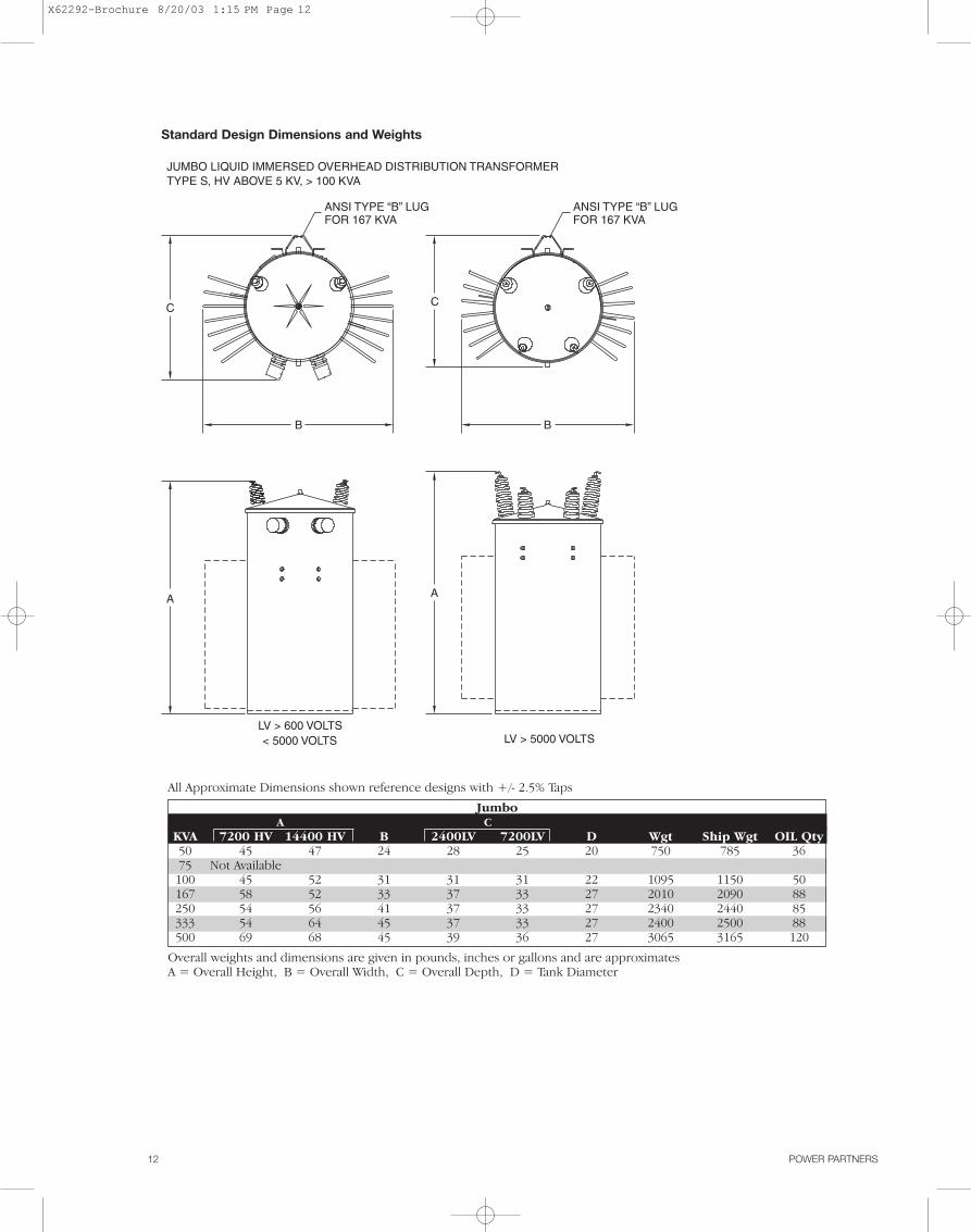
All Approximate Dimensions shown reference designs with +/- 2.5% Taps
JumboA C
KVA 7200 HV 14400 HV B 2400LV 7200LV D Wgt Ship Wgt OIL Qty50 45 47 24 28 25 20 750 785 3675 Not Available
100 45 52 31 31 31 22 1095 1150 50167 58 52 33 37 33 27 2010 2090 88250 54 56 41 37 33 27 2340 2440 85333 54 64 45 37 33 27 2400 2500 88500 69 68 45 39 36 27 3065 3165 120
Overall weights and dimensions are given in pounds, inches or gallons and are approximatesA = Overall Height, B = Overall Width, C = Overall Depth, D = Tank Diameter
JUMBO LIQUID IMMERSED OVERHEAD DISTRIBUTION TRANSFORMERTYPE S, HV ABOVE 5 KV, > 100 KVA
LV > 600 VOLTS < 5000 VOLTS LV > 5000 VOLTS
ANSI TYPE “B” LUGFOR 167 KVA
ANSI TYPE “B” LUGFOR 167 KVA
C
B
C
B
A A
Standard Design Dimensions and Weights
X62292-Brochure 8/20/03 1:15 PM Page 12

POWER PARTNERS 13
The Power Partners Triplex overhead distribution trans-former can be used to serve three phase applicationsthrough 225 kVA. Triplex designs consist of three sepa-rate single-phase core-coil assemblies in one tank.
Triplex overhead distribution transformers are often usedto serve large motor loads where the motors are fre-quently started. Oil field pumping loads and some irriga-tion pumping loads should use only triplex designs. Also,the Triplex transformer has international applicationswhere Dy 5 and Dy 11 phase displacement are required.
Ratings• 30-225 kVA• 65°C rise• 60 Hertz standard, 50 Hertz optional• High Voltages: 13800 and below• Low Voltages: 208Y/120, 240 x 480, and 480Y/277• Transformer BIL Ratings
Transformer Primary Transformer BIL2400 60 kV4160 60 kV7200 75 kV8320 75 kV
12000 95 kV12470 95 kV13200 95 kV13800 95 kV
Advantages• Easier, cleaner installations are provided by three
phase overhead transformers compared to three single-phase units.
• Reduced installation costs, lower operating costs, safer operation, minimized service disruptions, andincreased transformer life provided by an optional CSPprotection package.
• The capability to serve large motor loads requiring fre-quent motor starting is provided by triplex designs.
• The same design, manufacturing and performanceadvantages that are provided on Power Partners singlephase overhead distribution transformers are incorpo-rated into the triplex design.
Features1. Wound core with step-lap joints for increased
efficiency and lower noise levels.2. Progressively wound coils with adhesive resins on
insulating paper or conductors for increased short-circuit strength, efficiency and thermal strength.
3. CSP protection package available as an option forincreased protection against surge currents, shortcircuits and overloads:• Primary protective links • Surge arresters• Secondary circuit breaker• Secondary breaker operating handle with emer-
gency overload reset and overload signal light.4. Three point core-coil bracing for increased mechani-
cal strength.5. Self-venting and resealing cover that eliminates the
need for an auxiliary pressure relief device and offersincreased safety through higher tank withstand.
6. The paint finish process applies a durable, corrosionresistant finish to the product. The finish meets orexceeds all the performance requirements of ANSIC57.12.28. The multi-step process includes an epoxyprimer uniformly applied by cationic electrodeposi-tion and a urethane top coat.
7. Cover has 13 mils minimum of polyester coating providing 15 kV dielectric insulation of tank groundparts from live parts and increasing resistance to corrosion. The cover is sloped 15° preventing waterfrom collecting, thereby reducing the chances of corrosion and leaking.
8. Tank bottom rim is three layers thick for increaseddurability and resistance to shipping and handlingdamage.
Three Phase Triplex Overhead Distribution Transformer
X62292-Brochure 8/20/03 1:15 PM Page 13

14 POWER PARTNERS
Overall weights and dimensions are given in pounds, inches or gallons and are approximatesA = Overall Height, B = Overall Width, C = Overall Depth, D = Tank Diameter, E = Hanger Spacing
High Voltages 4160GY/2400, 7200GY/4160, 8320GY/4800KVA A B C D E* Wgt Ship Wgt OIL Qty30 53 26 25 17.5 11.25 760 805 4045 57 26 25 17.5 23.25 915 960 4575 61 33 28 20 23.25 1120 1165 60
112.5 61 34 28 20 36 1540 1585 58150 73 35 30 22 36 2455 2525 90225 76 35 30 22 36 2650 2745 90
High Voltages 12470GY/7200, 14400GY/8320KVA A B C D E* Wgt Ship Wgt OIL Qty30 58 23 25 17.5 11.25 760 805 4045 62 23 25 17.5 23.25 920 965 4575 66 29 28 20 23.25 1310 1355 60
112.5 66 34 28 20 36 1540 1585 58150 78 31 30 22 36 2470 2540 90225 81 31 30 22 36 2650 2745 90
High Voltages 20780GY/12000, 21590GY/12470, 22860/GY13200, 23900GY/13800KVA A B C D E* Wgt Ship Wgt OIL Qty
30 65 23 25 17.5 11.25 940 985 4545 68 26 28 20 23.25 1290 1340 6075 68 26 28 20 23.25 1340 1365 58
112.5 68 34 28 20 36 1540 1585 58150 80 31 30 22 36 2470 2540 90225 83 31 30 22 36 2650 2745 90
*E is the distance between the hanger brackets.
Standard Design Dimensions and Weights (All weights and dimensions are approximate.)
HV > 5000 HV < 5000
B
C
B
C
A A
DD
X62292-Brochure 8/20/03 1:15 PM Page 14

POWER PARTNERS 15
The Power Partners “T-connected,” overhead distributiontransformer can be used to serve most three phase appli-cations up to 500 kVA. “T-connected” transformers con-sist of two single-phase core/coil assemblies. This type ofconnection is also referred to as a “Scott-T” connection.“T-connected”, overhead distribution transformers canbe used to serve most three-phase applications.However, Triplex designed three phase transformers areneeded for some applications where large motors arethe load and these motors are frequently started. Oilfield pumping loads and some irrigation pumping loadsshould use only the triplex designs.
Ratings• 30-500 kVA• 65°C rise• 60 Hertz standard, 50 Hertz optional• High Voltages: 13800 and below• Low Voltages: 208T/120, 240T x 480T, and 480T/277• Transformer BIL Ratings
Transformer Primary Transformer BIL2400T 60 kV4160T 60 kV4800T 60 kV7200T 75 kV8320T 75 kV
12000T 95 kV12470T 95 kV13200T 95 kV13800T 95 kV
Advantages• Easier, more economical and cleaner installations are
provided by three phase overhead transformers com-pared to three single-phase units.
• Lighter weight and lower cost provided by “T-connected”design compared to conventional three-phase design.
• Elimination of overloads from system unbalance byoperating “T-connected” transformers without primarygrounds.
• Avoidance of transformer neutral requirement sincethird harmonic currents on “T-connected” transform-ers are negative sequence not requiring a ground path.
• Reduced installation costs, lower operating cost, saferoperation, minimized service disruptions andincreased transformer life provided by optional CSPcoordinated protection package.
• The same design, manufacturing and performanceadvantages that are provided on Power Partners singlephase overhead distribution transformers are incorpo-rated into “T-connected” design.
Features1. Wound core with step-lap joints for increased effi-
ciency and lower noise levels.2. Progressively wound coils with adhesive resins on
insulating paper or conductors for increased short-circuit strength and thermal strength.
3. Three point core-coil bracing for increased mechani-cal strength.
4. CSP protection package available as an option forincreased protection against surge currents, shortcircuits and overloads:• Primary protective links • Surge arresters• Secondary circuit breakers• Secondary breaker operating handle with emer-
gency overload reset and overload signal light.5. Self-venting and resealing cover that eliminates the
need for an auxiliary pressure relief device and offersincreased safety through higher tank withstand.
6. The paint finish process applies a durable, corrosionresistant finish to the product. The finish meets orexceeds all the performance requirements of ANSIC57.12.28. The multi-step process includes an epoxyprimer uniformly applied by cationic electrodeposi-tion and a urethane top coat.
7. Cover has 13 mils minimum of polyester coating providing 15 KV dielectric insulation of tank groundparts from live parts and increasing resistance to corrosion. The cover is sloped 15° preventing waterfrom collecting, thereby reducing the chances of corrosion and leaking.
8. Tank bottom rim is three layers thick for increaseddurability and resistance to shipping and handlingdamage.
Three Phase “T-connected” Overhead Distribution Transformer
X62292-Brochure 8/20/03 1:15 PM Page 15

16 POWER PARTNERS
Standard Design Dimensions and Weights (All weights and dimensions are approximate.)
HV > 5000 HV < 5000
B
C
B
C
A A
DD
Overall weights and dimensions are given in pounds, inches or gallons and are approximatesA = Overall Height, B = Overall Width, C = Overall Depth, D = Tank Diameter, E = Hanger Spacing
3 Phase T - T ConnectedHigh Voltages 2400T, 4160T, 4800TKVA A B C D E* Wgt Ship Wgt OIL Qty30 49 26 25 17.5 11.25 685 720 3545 49 29 28 20 23.25 990 1035 4475 49 33 28 20 23.25 1100 1175 52
112.5 57 31 30 22 36 1530 1625 62150 57 40 30 22 36 1770 1840 70225 61 37 34 24 36 2215 2303 81300 64 41 36 27 36 2750 2860 98500 78 45 42 27 3560 3650 118
High Voltages 12000T, 12470T, 13200T, 13800TKVA A B C D E* Wgt Ship Wgt OIL Qty30 54 23 25 17.5 11.25 700 735 3845 54 29 28 20 23.25 905 965 4375 54 33 28 20 23.25 1175 1225 50
112.5 62 33 30 22 36 1505 1565 59150 62 40 30 22 36 1725 1780 65225 61 37 34 24 36 2285 2275 84300 69 41 36 27 36 2915 3015 100500 80 45 42 27 3815 3900 123
*E is the distance between the hanger brackets.All Approximate Dimensions shown reference designs with +/- 2.5% Taps
X62292-Brochure 8/20/03 1:15 PM Page 16

POWER PARTNERS 17
The Power Partners commitment to manufacture qualitydistribution transformers is backed by a series of trans-former tests used to verify conformance to performance characteristics outlined in the latest revisions of ANSIC57.12.00 and ANSI C57.12.90. These identified tests arealso part of the Quality System which is audited semi-annu-ally by DET NOSKE VERITAS (DNV) to the ISO Standards.
Testing ProgramFactory tests are performed on a transformer to confirmthat it is properly designed and constructed to carryrated load and that it will withstand the conditions it willbe exposed to in service.
Each transformer manufactured by Power Partners mustundergo a series of tests.
1. Polarity, Phase-Relation, and Ratio2. Applied Voltage Test of the HV3. Applied Voltage Test of the LV4. Induced Voltage Test5. No-Load (Excitation) Loss and Excitation Current6. Circuit Breaker Test (for CSP transformers only)7. Impedance Voltage and Load Loss8. Full Wave Impulse 9. Continuity Check
Test FacilitiesThe multi-station, automated test facilities are operatedby process control computers. Required interaction withtest floor personnel is minimal with the computers initi-ating and monitoring each test, and then analyzing thetest results feedback. The computers are programmed toconduct tests according to ANSI standards, and accord-ing to the ratings of each transformer style, the test floorcomputers will initiate appropriate test setups, compareresults with established ANSI standard limits, and deter-mine acceptance for each tested unit.
The test results for each unit are recorded and stored oncomputer files for access and analysis.
Polarity, Phase-Relation, and Ratio TestsThese tests verify proper phase-relation (three phase),ratio, and polarity (single phase) of the transformer undertest. To pass, a unit must demonstrate the proper polarityor phase-relation and have a turns ratio within one-half ofone percent of the nominal voltage ratio.
Applied Voltage Test of the HVThis test checks the dielectric integrity of insulationstructures between the high voltage and low voltage, andbetween the high voltage and ground. A pass/fail deci-sion is made by monitoring the test current intensity. Ifthe resulting current is larger than specified normal leak-age and capacitive currents, the unit is rejected. This testis omitted for transformers with a permanently groundedhigh voltage winding.
Applied Voltage Test of LVThis dielectric test is similar to the Applied Voltage testof the high voltage circuitry except that the integrity ofinsulation structures between the low voltage and thehigh voltage, and between the low voltage and ground ischecked. A pass-fail decision is made by monitoring thetest current intensity. If the resulting current is largerthan specified normal leakage and capacitive current, the unit is rejected.
Induced Voltage TestThe principal purpose of this test is to verify the dielectricstrength of turn to turn, layer to layer, phase to phase,and other insulation structures within the transformerwindings by inducing an overvoltage condition (at higherthan normal frequency to avoid saturation of the core).The test current is monitored, and if it exceeds limitsspecified for each transformer, the unit is rejected.
No-Load Loss and Excitation CurrentThis test measures the no-load (excitation) loss and thetransformer exciting current with rated voltage applied.If the exciting current and/or the no-load loss exceed thelimits specified, the transformer is rejected.
Circuit Breaker Test (for CSP transformers only)This test verifies the proper operation of the low voltagecircuit breaker under fault conditions. The breaker isrequired to operate within a specified time under a simulated fault.
Impedance Voltage and Load LossThis test measures the load loss and the impedance volt-age at rated current. The load loss and the impedancevoltage must be within specified limits.
Full Wave ImpulseThe impulse test is one of several tests designed to verifythe dielectric strength of the many insulation structureswithin the distribution transformer against line voltagesurges. It is performed to comply with ANSI standardsand for quality assurance. The change in the ANSI stan-dard in 1993 required all manufacturers to install faultdetection sensitive enough to detect a single turn short.
Continuity CheckThis test is performed on all transformers to verify trans-former circuit and component integrity. This test is per-formed with an ohmmeter to verify that the internalwiring is correct. The transformer’s nameplate is compared to manufactur-ing information for style, serial number, kVA, HV rating,LV rating, tap voltages, impedance, conductor materialsand coil BIL rating. The bushings, electrical accessories,and fuses are verified.
Distribution Transformer Testing
X62292-Brochure 8/20/03 1:15 PM Page 17

18 POWER PARTNERS
Special TestsSome tests are performed at the option of the customer.
Sound TestingANSI standards define the required sound levels fortransformer but some customers specify reduced soundlevels. The sound generated by a transformer is affectedby the core geometry, flux density, tank design, and thequality of assembly of all the transformer componentsinto a completed unit. Sound tests are made with theunit powered at 100% and 110% of rated voltage underno-load conditions.
Temperature TestsCore losses and coil losses are the primary sources ofheating within the transformer. Our transformers areguaranteed to have an average coil winding temperatureof no more than 65° C rise over ambient air temperaturewhen operated at rated voltage and load conditions. The temperature test is performed to determine thethermal characteristics of the transformer and to verifythat they are within design limits.
CalibrationTest equipment is calibrated on a scheduled basis bytrained technicians. Calibration records are maintained inaccordance with the Quality System procedures. These areaudited semi-annually by DNV in accordance with ISO.
Short Circuit Withstand CapabilitiesDistribution transformers are subjected to external shortcircuits on the secondary side. Such external faults candevelop on the service line, in the house wiring or inconnected loads due to numerous environmental rea-sons. These faults can be line-to-ground, double line-to-ground or line-to-line.To meet these operating conditions, the AmericanNational Standard Institute (ANSI) has set standards con-cerning short circuit withstand capability. These stan-dards require that distribution transformers shall bedesigned and constructed to withstand the mechanicaland thermal stresses produced by these external shortcircuits.The current standards relating to short circuit strengthare ANSI C57.12.00 which sets the short circuit withstandrequirements for distribution transformers and ANSIC57.12.90 which provides procedures for short circuittesting.For distribution transformers, the magnitude of the shortcircuit current, the numbers of short-circuit tests and theduration of each short circuit test are defined by ANSIstandards as follows.
A. Magnitude
Single ThreePhase Phase Withstand
Category kVA kVA Capability*I 5-25 15-75 40
37.5-100 112.5-300 35
167-500 500 25
II 750-2500 1/ZT**
*Base current (Symmetrical) per unit for all distribution transformerswith secondary rated 600 V and below.
**The short circuit current will be limited by the transformer impedance only.
B. Number of TestsEach phase of the transformer shall be subjected to atotal of six tests, four with symmetrical fault currents andtwo with asymmetrical fault currents.
C. Duration of Short Circuit TestsWhen short circuit tests are performed the duration ofeach test shall be 0.25 s except that one test satisfying thesymmetrical current requirement shall be made for alonger duration on distribution transformers. The dura-tion of the long test in each case shall be as follows:
Category I:T=1250/I2
Where T is the duration in seconds,And I=Isc/IR=symmetrical short circuit current, in multiplesof normal base current except I shall not exceed the maxi-mum symmetrical current magnitudes listed in A.Where Isc=IR/ZT=symmetrical short circuit current, inrms amperesIR=rated current on the given tap connection, in rmsamperesZT=transformer impedance on the given tap connectionin per unit on the same apparent power base as IR
Category II:T=1.0 second
Criteria of Satisfactory PerformanceAccording to ANSI Standards a unit is considered to havepassed the test if it passes a visual inspection and dielec-tric tests. Recommended additional checks includeexamination of wave shape of terminal voltage and cur-rent, leakage impedance measurement and excitationcurrent test. (Refer to ANSI C57.12.90.)The standard allows the following variations in the leak-age impedance:
ZT (Per Units) Percentage Variation0.0299 or less 22.5-500 (ZT)0.0300 or more 7.5
ZT=per unit impedance of the transformer
X62292-Brochure 8/20/03 1:15 PM Page 18

POWER PARTNERS 19
The Power Partners factory utilizes a paint finish processcalled “2CEC”, a trademark for a two-coat cathodic elec-trodeposition paint process. This new advanced coatingtechnique maintains the structural integrity of transform-ers that are subjected to the long-term corrosive environ-ments of coastal areas and industrial contaminants.
Paint ProcessCathodic electrodeposition of paint occurs when directcurrent is applied to positively charged resin micellesdispersed in water. The resin micelles migrate toward thecathode (transformer tank) and are deposited in a pro-cess known as electrophoresis. As the process continues,the thickness of the deposit builds, resistance increases,and the film reaches a thickness limit. The most accessi-ble areas are coated first, but as the resistance increases,less accessible areas coat, producing a highly uniformfilm build. Two-coat cathodic electrodeposition is theapplication of two coats of paint (epoxy primer/acrylicurethane topcoat).
Paint PretreatmentPrior to welding to the tank shell, stamped external hard-ware such as hanger brackets and lifting lugs are vibra-tory finished to remove burrs and insure a smooth radiusedge to allow consistent edge coating.An eight-stage dip process provides two cleaning steps tocompletely remove lubricants and soils. A zinc phos-phate coating is applied to enhance corrosion protectionby providing tighter, more consistent coating than thetypically used iron phosphate. The use of deionizedwater in the final rinse stages insures that the surface isfree of salts and ions that could later provide sites forcorrosion initiation. All pretreatment stages are immer-sion stages, which assures complete and total coverage.The electrodeposition process assures complete andconsistent coverage of the entire tank including complexshapes such as fins, hanger brackets, and lifting lugs.The “2CEC” process allows us to optimize the perfor-mance of the primer and topcoat independently to maxi-mize corrosion protection and ultraviolet light resistancewhile maintaining superior mechanical properties.Paint process consistency is assured through automatedpaint feed and monitoring of a real time basis. Paint sys-tem operators monitor and audit the process.
Advantages of the Process1. Complete and uniform coverage of complex shapes,
including edges and corners, hanger brackets,ground pads, and tank bottoms.
2. Access into partially closed areas, such as inside thehanger brackets.
3. High solids film eliminates sagging problems.4. Minimal organic solvent content.
ANSI C57.12.28 Performance RequirementsANSI Standard C57.12.28 served as the benchmark forperformance on the tests listed below. The test resultsclearly indicate the two-coat cathodic electrodepositionto be a leader in corrosion resistance, while maintainingexcellent performance in all areas of the ANSI standard.“2CEC” passed all the tests listed here.
Salt Spray TestPanels are scribed to bare metal and tested for 1000hours in a 5% salt spray per ASTM B117-85E1 and evalu-ated per ASTM D1654-79A. Loss of adhesion from baremetal must not exceed more than 1/8" from the scribe.Underfilm corrosion must not exceed more than 1/16"from the scribe.
Crosshatch Adhesion TestPanels are scribed to bare metal with a crosshatch pat-tern and tested per ASTM D3359-83. There must be100% adhesion to the bare metal and between layers.
Humidity TestPanels must be tested for 1000 hours in accordance withASTM D2247-86A. There must be no blisters.
Impact TestTest panels were impacted per ASTM D2794-84 at 160 in.-lbs. of impact. There must be not chipping of the painton the impact side of the test panel.
Oil Resistance TestOil resistance testing is conducted at both 100°C andambient for 72 hours. There must be no apparentchanges, such as color shift, blisters, loss of hardness, orstreaking.
Ultraviolet Accelerated Weathering TestTest panels must be exposed for 500 hours in accordancewith ASTM G53-84. Loss of gloss must not exceed 50% ofthe original gloss as described in ASTM D523-85E1.
Abrasion Resistance—Taber Abraser TestThe total coating system must be tested using a CS-10wheel, 1000-gram weight, in accordance with ASTMD4060-84. The number of abrasion required to wear thecoating through to the substrate must be at least 3000cycles.The ANSI C57.120.28 test results clearly indicate the two-coat cathodic electrodeposition is a leader in corrosionresistance while maintaining excellent performance in allareas of the ANSI standard. The two-coat cathodic elec-trodeposition maintains consistent, uniform paint cover-age over the entire product, with no runs or sags, andoffering a superior coating on distribution transformers.
Paint Finish Process
X62292-Brochure 8/20/03 1:15 PM Page 19

Power PartnersOverhead Transformers200 Newton Bridge RoadAthens, GA 30607Phone 706-548-3121July, 2003
ISO CertifiedJuly, 2003
X62292-Brochure 8/20/03 1:15 PM Page 20