about microcontroller trainers microcontroller … - uc.pdf · about microcontroller trainers ......
TRANSCRIPT
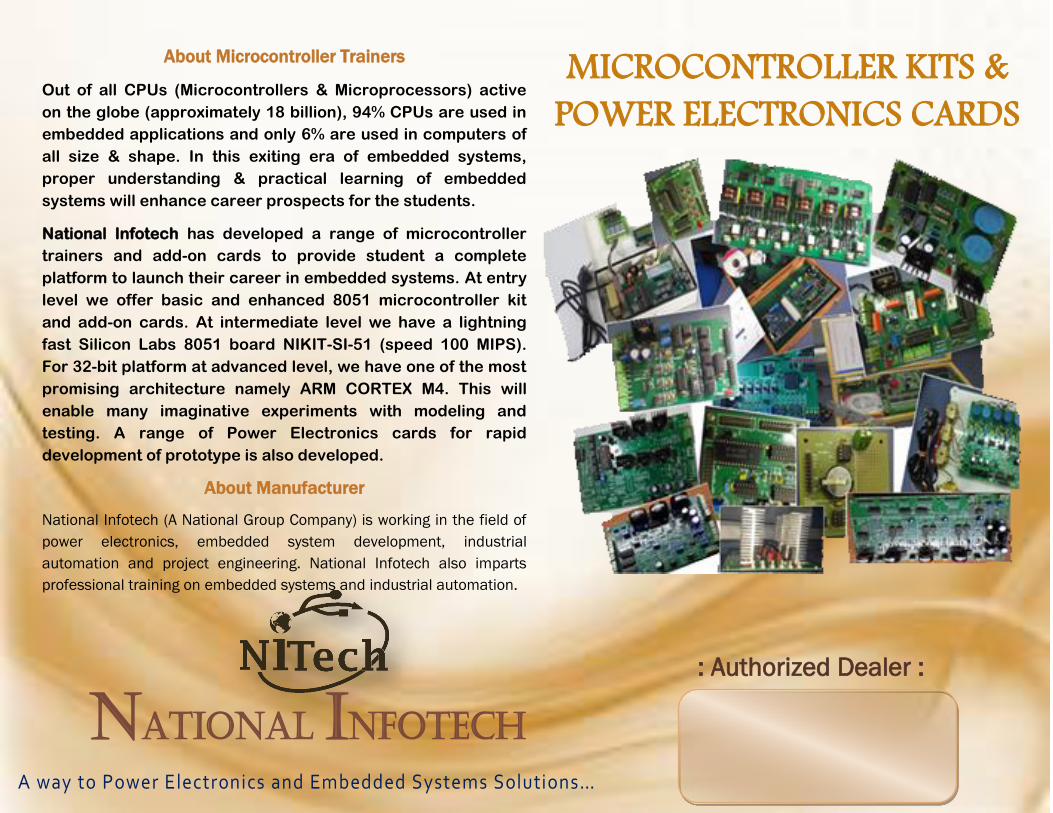
About Microcontroller Trainers
Out of all CPUs (Microcontrollers & Microprocessors) active
on the globe (approximately 18 billion), 94% CPUs are used in
embedded applications and only 6% are used in computers of
all size & shape. In this exiting era of embedded systems,
proper understanding & practical learning of embedded
systems will enhance career prospects for the students.
National Infotech has developed a range of microcontroller
trainers and add-on cards to provide student a complete
platform to launch their career in embedded systems. At entry
level we offer basic and enhanced 8051 microcontroller kit
and add-on cards. At intermediate level we have a lightning
fast Silicon Labs 8051 board NIKIT-SI-51 (speed 100 MIPS).
For 32-bit platform at advanced level, we have one of the most
promising architecture namely ARM CORTEX M4. This will
enable many imaginative experiments with modeling and
testing. A range of Power Electronics cards for rapid
development of prototype is also developed.
About Manufacturer
National Infotech (A National Group Company) is working in the field of
power electronics, embedded system development, industrial
automation and project engineering. National Infotech also imparts
professional training on embedded systems and industrial automation.
MICROCONTROLLER KITS &
POWER ELECTRONICS CARDS
National Infotech A way to Power Electronics and Embedded Systems Solutions…
: Authorized Dealer :
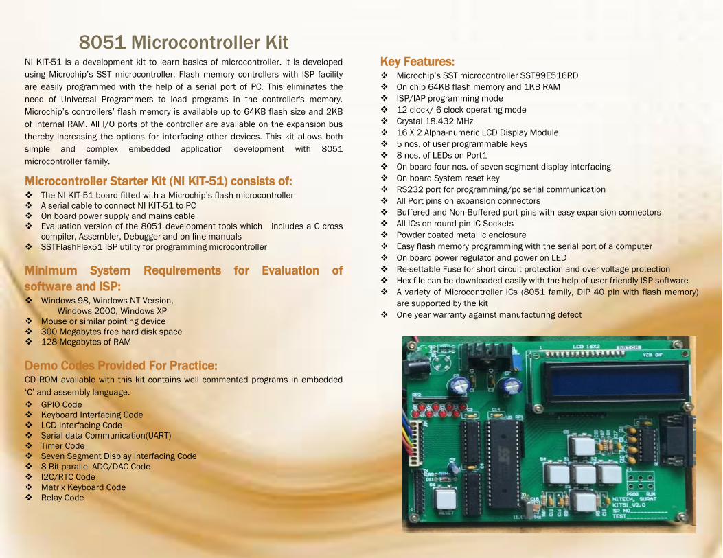
8051 Microcontroller Kit NI KIT-51 is a development kit to learn basics of microcontroller. It is developed
using Microchip’s SST microcontroller. Flash memory controllers with ISP facility
are easily programmed with the help of a serial port of PC. This eliminates the
need of Universal Programmers to load programs in the controller's memory.
Microchip’s controllers’ flash memory is available up to 64KB flash size and 2KB
of internal RAM. All I/O ports of the controller are available on the expansion bus
thereby increasing the options for interfacing other devices. This kit allows both
simple and complex embedded application development with 8051
microcontroller family.
Microcontroller Starter Kit (NI KIT-51) consists of: The NI KIT-51 board fitted with a Microchip’s flash microcontroller
A serial cable to connect NI KIT-51 to PC
On board power supply and mains cable
Evaluation version of the 8051 development tools which includes a C cross
compiler, Assembler, Debugger and on-line manuals
SSTFlashFlex51 ISP utility for programming microcontroller
Minimum System Requirements for Evaluation of
software and ISP: Windows 98, Windows NT Version,
Windows 2000, Windows XP
Mouse or similar pointing device
300 Megabytes free hard disk space
128 Megabytes of RAM
Demo Codes Provided For Practice: CD ROM available with this kit contains well commented programs in embedded
‘C’ and assembly language.
GPIO Code
Keyboard Interfacing Code
LCD Interfacing Code
Serial data Communication(UART)
Timer Code
Seven Segment Display interfacing Code
8 Bit parallel ADC/DAC Code
I2C/RTC Code
Matrix Keyboard Code
Relay Code
Key Features: Microchip’s SST microcontroller SST89E516RD
On chip 64KB flash memory and 1KB RAM
ISP/IAP programming mode
12 clock/ 6 clock operating mode
Crystal 18.432 MHz
16 X 2 Alpha-numeric LCD Display Module
5 nos. of user programmable keys
8 nos. of LEDs on Port1
On board four nos. of seven segment display interfacing
On board System reset key
RS232 port for programming/pc serial communication
All Port pins on expansion connectors
Buffered and Non-Buffered port pins with easy expansion connectors
All ICs on round pin IC-Sockets
Powder coated metallic enclosure
Easy flash memory programming with the serial port of a computer
On board power regulator and power on LED
Re-settable Fuse for short circuit protection and over voltage protection
Hex file can be downloaded easily with the help of user friendly ISP software
A variety of Microcontroller ICs (8051 family, DIP 40 pin with flash memory)
are supported by the kit
One year warranty against manufacturing defect
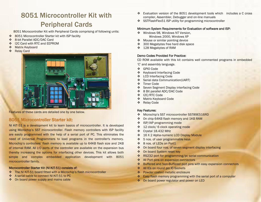
8051 Microcontroller Kit with
Peripheral Cards 8051 Microcontroller Kit with Peripheral Cards comprising of following units:
8051 Microcontroller Starter kit with ISP facility
8-bit Parallel ADC/DAC Card
I2C Card with RTC and EEPROM
Matrix Keyboard
Relay Card
Features of these cards are detailed one by one below.
8051 Microcontroller Starter kit:
NI KIT-51 is a development kit to learn basics of microcontroller. It is developed
using Microchip’s SST microcontroller. Flash memory controllers with ISP facility
are easily programmed with the help of a serial port of PC. This eliminates the
need of Universal Programmers to load programs in the controller's memory.
Microchip’s controllers’ flash memory is available up to 64KB flash size and 2KB
of internal RAM. All I/O ports of the controller are available on the expansion bus
thereby increasing the options for interfacing other devices. This kit allows both
simple and complex embedded application development with 8051
microcontroller family.
Microcontroller Starter Kit (NI KIT-51) consists of:
The NI KIT-51 board fitted with a Microchip’s flash microcontroller
A serial cable to connect NI KIT-51 to PC
On board power supply and mains cable
Evaluation version of the 8051 development tools which includes a C cross
compiler, Assembler, Debugger and on-line manuals
SSTFlashFlex51 ISP utility for programming microcontroller
Minimum System Requirements for Evaluation of software and ISP:
Windows 98, Windows NT Version,
Windows 2000, Windows XP
Mouse or similar pointing device
300 Megabytes free hard disk space
128 Megabytes of RAM
Demo Codes Provided For Practice:
CD ROM available with this kit contains well commented programs in embedded
‘C’ and assembly language.
GPIO Code
Keyboard Interfacing Code
LCD Interfacing Code
Serial data Communication(UART)
Timer Code
Seven Segment Display interfacing Code
8 Bit parallel ADC/DAC Code
I2C/RTC Code
Matrix Keyboard Code
Relay Code
Key Features:
Microchip’s SST microcontroller SST89E516RD
On chip 64KB flash memory and 1KB RAM
ISP/IAP programming mode
12 clock/ 6 clock operating mode
Crystal 18.432 MHz
16 X 2 Alpha-numeric LCD Display Module
5 nos. of user programmable keys
8 nos. of LEDs on Port1
On board four nos. of seven segment display interfacing
On board System reset key
RS232 port for programming/pc serial communication
All Port pins on expansion connectors
Buffered and Non-Buffered port pins with easy expansion connectors
All ICs on round pin IC-Sockets
Powder coated metallic enclosure
Easy flash memory programming with the serial port of a computer
On board power regulator and power on LED
Re-settable Fuse for short circuit protection and over voltage protection
Hex file can be downloaded easily with the help of user friendly ISP software
A variety of Microcontroller ICs (8051 family, DIP 40 pin with flash memory)
are supported by the kit
One year warranty against manufacturing defect
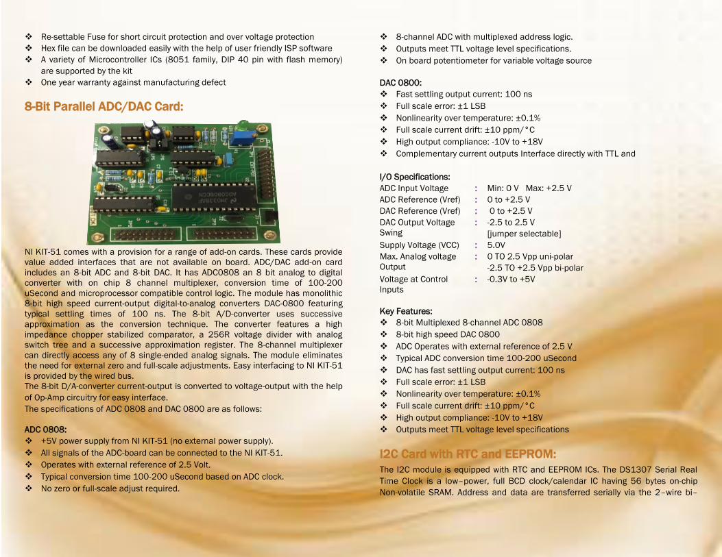
8-Bit Parallel ADC/DAC Card:
NI KIT-51 comes with a provision for a range of add-on cards. These cards provide
value added interfaces that are not available on board. ADC/DAC add-on card
includes an 8-bit ADC and 8-bit DAC. It has ADC0808 an 8 bit analog to digital
converter with on chip 8 channel multiplexer, conversion time of 100-200
uSecond and microprocessor compatible control logic. The module has monolithic
8-bit high speed current-output digital-to-analog converters DAC-0800 featuring
typical settling times of 100 ns. The 8-bit A/D-converter uses successive
approximation as the conversion technique. The converter features a high
impedance chopper stabilized comparator, a 256R voltage divider with analog
switch tree and a successive approximation register. The 8-channel multiplexer
can directly access any of 8 single-ended analog signals. The module eliminates
the need for external zero and full-scale adjustments. Easy interfacing to NI KIT-51
is provided by the wired bus.
The 8-bit D/A-converter current-output is converted to voltage-output with the help
of Op-Amp circuitry for easy interface.
The specifications of ADC 0808 and DAC 0800 are as follows:
ADC 0808:
+5V power supply from NI KIT-51 (no external power supply). All signals of the ADC-board can be connected to the NI KIT-51.
Operates with external reference of 2.5 Volt.
Typical conversion time 100-200 uSecond based on ADC clock.
No zero or full-scale adjust required.
8-channel ADC with multiplexed address logic.
Outputs meet TTL voltage level specifications.
On board potentiometer for variable voltage source
DAC 0800:
Fast settling output current: 100 ns
Full scale error: ±1 LSB
Nonlinearity over temperature: ±0.1%
Full scale current drift: ±10 ppm/°C
High output compliance: -10V to +18V
Complementary current outputs Interface directly with TTL and
I/O Specifications:
ADC Input Voltage : Min: 0 V Max: +2.5 V
ADC Reference (Vref) : 0 to +2.5 V
DAC Reference (Vref) : 0 to +2.5 V
DAC Output Voltage
Swing : -2.5 to 2.5 V
[jumper selectable]
Supply Voltage (VCC) : 5.0V
Max. Analog voltage
Output : 0 TO 2.5 Vpp uni-polar
-2.5 TO +2.5 Vpp bi-polar
Voltage at Control
Inputs : -0.3V to +5V
Key Features:
8-bit Multiplexed 8-channel ADC 0808
8-bit high speed DAC 0800
ADC Operates with external reference of 2.5 V
Typical ADC conversion time 100-200 uSecond
DAC has fast settling output current: 100 ns
Full scale error: ±1 LSB
Nonlinearity over temperature: ±0.1%
Full scale current drift: ±10 ppm/°C
High output compliance: -10V to +18V
Outputs meet TTL voltage level specifications
I2C Card with RTC and EEPROM:
The I2C module is equipped with RTC and EEPROM ICs. The DS1307 Serial Real
Time Clock is a low–power, full BCD clock/calendar IC having 56 bytes on-chip
Non-volatile SRAM. Address and data are transferred serially via the 2–wire bi–

directional I2C bus. AT24C04A is a 4K x 8 (512
Kbit) Serial Electrically Erasable PROM (EEPROMs).
It has been developed for advanced, low-power
applications such as personal communications and
data acquisition. This device also has a page write
capability of up to 128 bytes of data. Easy
interfacing to NI KIT-51 is provided by the wired
bus.
I/O Specifications:
Supply Voltage (VCC) : 5.0V
RTC : (SCL, SDA, X2, X1, V, SQW / OUT)
EEPROM : (SCL, SDA, A2, A1, A0, WP)
Specifications:
RTC Specifications:
+5 V power supply from NI KIT-51 (no external
power supply).
All signals of the I2C-board can be connected
to the NI KIT-51.
Easy interface to all microcontrollers.
Real time clock counts seconds, minutes,
hours, date of month, month, day of week and
year with leap year compensation valid up to
2100.
56 byte nonvolatile SRAM for general data
storage.
2-Wire Serial interface (I2C).
Programmable Square-Wave Output Signal.
Automatic power fail detect.
Consumes less than 500 nA for battery back-up
at 25'C.
EEPROM Specifications:
Internally Organized 128 x 8 (1K), 256 x 8 (2K),
512 x 8 (4K), 1024 x 8 (8K) or 2048 x 8 (16K)
2-Wire Serial Interface (I2C)
Schmitt Trigger, Filtered Inputs for Noise
Suppression
Bidirectional Data Transfer Protocol
100 kHz (1.8V, 2.5V, 2.7V) and 400 kHz (5V)
Compatibility
Write Protect Pin for Hardware Data Protection
8-Byte Page (1K, 2K), 16-Byte Page (4K, 8K,
16K) Write Modes
Partial Page Writes Are Allowed
Self-Timed Write Cycle (10 ms max)
High Reliability
Endurance: 1 Million Write Cycles
Data Retention: 100 Years
ESD Protection: >3000V
Automotive Grade and Extended Temperature
Devices Available
8-Pin and 14-Pin JEDEC SOIC, 8-Pin PDIP, 8-Pin
MSOP, and 8-Pin TSSOP Packages 2-Wire
Key Features:
Real time clock valid up to 2100.
RTC IC DS1307 with 56 bytes of battery backed
nonvolatile SRAM
2-Wire Serial interface (I2C)
Programmable Square-Wave Output Signal
Automatic power fail detect
256 x 8 bits or 256 bytes EEPROM
Schmitt Trigger, Filtered Inputs for Noise
Suppression
Bidirectional Data Transfer Protocol
Write Protect Pin for Hardware Data Protection
8-Byte Page (2K)
Write Modes up to 400 kHz I2C clock rate
Partial Page Writes Are Allowed
Applications:
RTC Applications:
Digital Clock
Attendance System
Digital Camera
In Applications where time stamp is needed
EEPROM Applications:
In Real Time Clock
Digital Temperature Sensors
To Store Calibration Information
To Store the data that needs to be available on
the event of power loss
Relay Card: 4-Channel Relay interface board
Equipped with high-current relay, Rating are as
follows:
1) 7A-250V AC
2) 10A-125V AC
3) 12A 120V DC
4) 10A 28V DC
Standard interface that can be controlled
directly by microcontroller
Has the fixed bolt hole and easy installation
Small board PCB size
four ways of relay status indicator LED (red)
Module interface specifications (6 wires)
External 12V
GND (external GND)
1N1-1N4 interchange relay control interface by
single chip IO
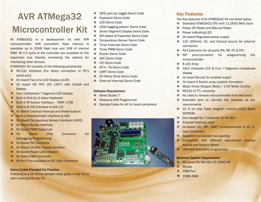
AVR ATMega32
Microcontroller Kit NI ATMEGA32 is a development kit with AVR
microcontroller. AVR controllers’ flash memory is
available up to 32KB flash size and 2KB of internal
RAM. All I/O ports of the controller are available on the
expansion bus thereby increasing the options for
interfacing other devices.
ATMEGA32 Kit consists of the following peripherals:
RS-232 Interface (For direct connection to PC’s
serial port)
On board Two Line LCD Display (2x16)
On board I2C RTC (DS 1307) with Crystal and
Battery
Four multiplexed 7-Segment LED Display
Built in Pull-Up (5 Keys) Keyboard
Built in IR Sensor Interface – TSOP 1738
Built in 8 LED Interface to test I/O
On Board External Interrupt and Reset buttons
Built in Potentiometer interface to ADC
On Board Temperature Sensor Interface (LM35)
On Board Buzzer Interface
On Board PWM Output pin
On Board JTAG Connector for
Debugging/Programming
On Board ISP Connector
On Board 16 MHz Crystal Oscillator
On Board Power LED Indicator
On Board DB9 Connector
All Port Pins available at IDC (2x5) Connector
Demo Codes Provided For Practice:
Following is a list of the sample codes given in the CD to
start working with the kit.
GPIO port pin toggle Demo Code
Keyboard Demo Code
LCD Demo Code
LEDs toggling pattern Demo Code
Seven Segment Display Demo Code
SPI based IO Expander Demo Code
Temperature Sensor Demo Code
Timer Interrupt Demo Code
Timer PWM Demo Code
Buzzer Demo Code
ADC Demo Code
I2C Demo Code
IR Tx - Rx Demo Code
UART Demo Code
DC Motor Drive Demo Code
External Interrupt Demo Code
Software Requirement:
Atmel Studio 7
Khazama AVR Programmer
Sample Codes for all On board peripheral
Key Features: The Key features of NI ATMEGA32 Kit are listed below:
Standard ATMEGA32 CPU with 11.0592 MHz clock
Power ON Reset and Manual Reset
Power indicating LED
On board Regulated power supply
12V (300mA), 5V, and Ground source for external
connection
Port Extension for all ports (PA, PB, PC & PD)
ISP pins/connector for programming the
microcontroller
8 LED Array
16x2 character LCD & Four 7-Segment multiplexed
display
On board Buzzer for audible output
On board 5 Switch array (joystick formation)
Motor Driver Stepper Motor / 2 DC Motor Control
RS232 to TTL converter
No need to remove microcontroller from the board
Extended pins to connect the modules as per
requirements
32 K on chip Flash program memory,1024 Bytes
EEPROM
One header for 7 channels 10 bit ADC
External interrupt input
On-board I2C, SPI, UART connectors(with 9 pin D-
type Connector)
Supplied in a wooden box packing
Compatible with different educational practice
boards and Arduino Board
USB ASP third party programmer
Minimum System Requirement:
Windows 95/98/ME/NT/2000/XP
Mouse
COM Port
16Mb RAM

SI Labs Advanced
8051
Microcontroller Kit SI Labs Advanced 8051 Microcontroller Kit (NI KIT-SI-
51) is 100 MIPS 8051 microcontroller family. It is
developed for the Silicon Laboratories’ C8051F12x
Development Kit containing C8051F120 Target Board,
JTAG Debugger, IDE and other accessories. A 96-pin
Expansion I/O connector is provided on C8051F120
Target Board which can be connected to Silicon
Laboratories’ Buffer Card using EURO 96 connector. All
I/O pins of Silicon Laboratories’ Buffer Card are buffered
and interfacing keyboard, LCD, DI, DO, AI, AO, LED,
Serial Communication made 5 V tolerance and easy. On-
chip MAC unit for fast calculation, on-chip 12-bit 8-
channel ADC (100KSPS), on-chip 10bit DAC are other
useful feature on 8051 core of this kit.
Key Features: High-Speed pipelined 8051-compatible CIP-51
microcontroller core (up to 100 MIPS)
In-system, full-speed, non-intrusive debug
interface (on-chip)
50 MIPS for C8051F124/5/6/7)
On-chip MAC Unit for fast calculation
Buffered 5 V Tolerance I/O pins
Keyboard Interfacing
16 X 2 LCD Interfacing
2 UART for Serial Communication
Analog output with adjustable gain
On-chip 12-bit 8-channel ADC (100 KSPS)with
PGA and 8-channel analog multiplexer
On-chip 8-bit 8-channel ADC (500 KSPS)
On-chip 10 bit DAC with programmable update
scheduling
128k bytes of in-system programmable FLASH
memory
8448 (8k + 256) bytes of on-chip RAM
External Data Memory Interface with 64k byte
address space
SPI, SMBus/I2C, and two UART serial interfaces
implemented in hardware
Programmable Counter/Timer Array with 6
capture/compare modules
On-chip Watchdog Timer, VDD Monitor, and
Temperature Sensor
LED on Port pins
Five general purpose 16-bit Timers
+5 V Regulated Power Supply
DSP Experiments possible
With on-chip VDD monitor, Watchdog Timer,
and clock oscillator, the C8051F12x devices
are truly stand-alone System-on-a-Chip
solutions
On-board JTAG debug circuitry allows non-
intrusive (uses no on-chip resources), full
speed, in-circuit debugging using the production
MCU installed in the final application
Each MCU is specified for 2.7 V-to-3.6 V
operation over the industrial temperature range
(-45° C to +85° C)
The Port I/Os, /RST, and JTAG pins are tolerant
for input signals up to 5 V
All analog and digital peripherals are
enabled/disabled and configured by user
firmware
The FLASH memory can be reprogrammed even
in-circuit, providing non-volatile data storage,
and also allowing field upgrades of the 8051
firmware.
Minimum System Requirements for
Evaluation of software and ISP:
Windows 98, Windows NT Version 4, Windows
2000, Windows XP
Mouse or Similar Pointing Device
300 Megabytes Free Hard Disk Space
128 Megabytes of RAM
Silicon Laboratories IDE
USB Debug Adapter
JTAG interface
Demo Codes Provided For Practice:
GPIO demo code using key/LED Timer demo code using PLL External Crystal demo code Timer 0 in 16bit mode demo code Timer 2 demo code for toggling a variable PCA demo code UART transmission demo code ADC demo code by UART ADC demo code by PCA NI-Advanced-SI-51 all peripheral demo code
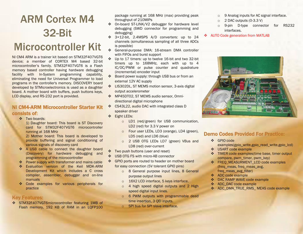
ARM Cortex M4
32-Bit
Microcontroller Kit NI CM4 ARM is a trainer kit based on STM32F407VGT6
device; a member of CORTEX M4 based 32-bit
microcontroller’s family. STM32F407VGT6 is a Flash
memory based controller having hardware debugging
facility with In-System programming capability,
eliminating the need for Universal Programmer to load
programs in the controller's memory. DISCOVERY board
developed by STMicroelectronics is used as a daughter
board. A mother board with buffers, push buttons keys,
LCD display, and RS-232 port is provided.
NI CM4-ARM Microcontroller Starter Kit
consists of: Two boards:
1) Daughter board: This board is ST Discovery
card for STM32F407VGT6 microcontroller
running at 168 MHz
2) Mother board: This board is developed to
provide buffering and signal conditioning of
various signals of discovery card
A USB cable to connect the daughter board
(Discovery) for hardware debugging and
programming of the microcontroller
Power supply with transformer and mains cable
Evaluation version of the Keil MDK-ARM
Development Kit which includes a C cross
compiler, assembler, debugger and on-line
manuals
Code examples for various peripherals for
practice
Key Features: STM32F407VGT6microcontroller featuring 1MB of
Flash memory, 192 KB of RAM in an LQFP100
package running at 168 MHz (max) providing peak
throughput of 210MIPs
On-board ST-LINK/V2 debugger for hardware level
debugging (SWD connector for programming and
debugging)
3×12-bit, 2.4MSPS A/D converters: up to 24
channels (simultaneous sampling of all three ADCs
is possible)
General-purpose DMA: 16-stream DMA controller
with FIFOs and burst support
Up to 17 timers: up to twelve 16-bit and two 32-bit
timers up to 168MHz, each with up to 4
IC/OC/PWM or pulse counter and quadrature
(incremental) encoder input
Board power supply: through USB bus or from an
external 12V AC supply
LIS302DL, ST MEMS motion sensor, 3-axis digital
output accelerometer
MP45DT02, ST MEMS audio sensor, Omni-
directional digital microphone
CS43L22, audio DAC with integrated class D
speaker driver
Eight LEDs:
o LD1 (red/green) for USB communication,
LD2 (red) for 3.3 V power on
o Four user LEDs, LD3 (orange), LD4 (green),
LD5 (red) and LD6 (blue)
o 2 USB OTG LEDs LD7 (green) VBus and
LD8 (red) over-current
Two push buttons (user and reset)
USB OTG FS with micro-AB connector
GPIO ports are routed to header on mother board
for easy connection (5V tolerant GPIO pins)
o 8 General purpose input lines, 8 General
purpose output lines
o 16X2 LCD interface, 5 keys interface.
o 4 high speed digital outputs and 2 High
speed digital input lines.
o 6 PWM outputs with programmable dead
time insertion, 3 QEI inputs.
o SPI bus for SPI slave interface.
o 9 Analog inputs for AC signal interface.
o 2 DAC outputs (0-3.3 V)
o 9-pin D-type connector for RS232
interfaces.
AUTO Code generation from MATLAB
Demo Codes Provided For Practice:
GPIO code
examples(gpio_write,gpio_read_write,gpio_lcd)
USART code example
TIMER code examples(time base, timer output
compare, pwm_timer, pwm_key)
FREQ_MEASURMENT_LCD code examples
(freq_meas, freq_meas_avg,
freq_meas_avg_filter)
ADC code example
DAC RAMP WAVE code example
ADC_DAC code example
ADC_DMA_TRUE_RMS_ MEAS code example
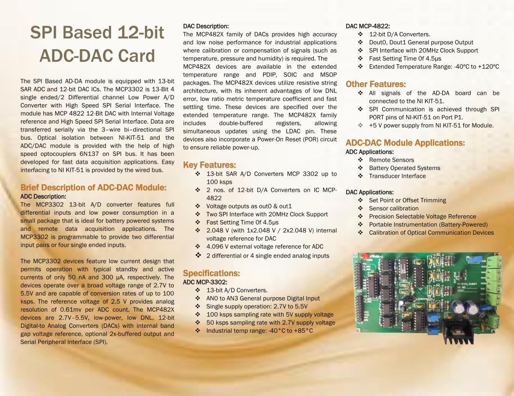
SPI Based 12-bit
ADC-DAC Card
The SPI Based AD-DA module is equipped with 13-bit
SAR ADC and 12-bit DAC ICs. The MCP3302 is 13-Bit 4
single ended/2 Differential channel Low Power A/D
Converter with High Speed SPI Serial Interface. The
module has MCP 4822 12-Bit DAC with Internal Voltage
reference and High Speed SPI Serial Interface. Data are
transferred serially via the 3–wire bi–directional SPI
bus. Optical isolation between NI-KIT-51 and the
ADC/DAC module is provided with the help of high
speed optocouplers 6N137 on SPI bus. It has been
developed for fast data acquisition applications. Easy
interfacing to NI KIT-51 is provided by the wired bus.
Brief Description of ADC-DAC Module: ADC Description:
The MCP3302 13-bit A/D converter features full
differential inputs and low power consumption in a
small package that is ideal for battery powered systems
and remote data acquisition applications. The
MCP3302 is programmable to provide two differential
input pairs or four single ended inputs.
The MCP3302 devices feature low current design that
permits operation with typical standby and active
currents of only 50 nA and 300 µA, respectively. The
devices operate over a broad voltage range of 2.7V to
5.5V and are capable of conversion rates of up to 100
ksps. The reference voltage of 2.5 V provides analog
resolution of 0.61mv per ADC count. The MCP482X
devices are 2.7V–5.5V, low-power, low DNL, 12-bit
Digital-to Analog Converters (DACs) with internal band
gap voltage reference, optional 2x-buffered output and
Serial Peripheral Interface (SPI).
DAC Description:
The MCP482X family of DACs provides high accuracy
and low noise performance for industrial applications
where calibration or compensation of signals (such as
temperature, pressure and humidity) is required. The
MCP482X devices are available in the extended
temperature range and PDIP, SOIC and MSOP
packages. The MCP482X devices utilize resistive string
architecture, with its inherent advantages of low DNL
error, low ratio metric temperature coefficient and fast
settling time. These devices are specified over the
extended temperature range. The MCP482X family
includes double-buffered registers, allowing
simultaneous updates using the LDAC pin. These
devices also incorporate a Power-On Reset (POR) circuit
to ensure reliable power-up.
Key Features: 13-bit SAR A/D Converters MCP 3302 up to
100 ksps
2 nos. of 12-bit D/A Converters on IC MCP-
4822
Voltage outputs as out0 & out1
Two SPI Interface with 20MHz Clock Support
Fast Setting Time 0f 4.5µs
2.048 V (with 1x2.048 V / 2x2.048 V) internal
voltage reference for DAC
4.096 V external voltage reference for ADC
2 differential or 4 single ended analog inputs
Specifications: ADC MCP-3302:
13-bit A/D Converters.
AN0 to AN3 General purpose Digital Input
Single supply operation: 2.7V to 5.5V
100 ksps sampling rate with 5V supply voltage
50 ksps sampling rate with 2.7V supply voltage
Industrial temp range: -40°C to +85°C
DAC MCP-4822:
12-bit D/A Converters.
Dout0, Dout1 General purpose Output
SPI Interface with 20MHz Clock Support
Fast Setting Time 0f 4.5µs
Extended Temperature Range: -40ºC to +120ºC
Other Features: All signals of the AD-DA board can be
connected to the NI KIT-51.
SPI Communication is achieved through SPI
PORT pins of NI-KIT-51 on Port P1.
+5 V power supply from NI KIT-51 for Module.
ADC-DAC Module Applications: ADC Applications:
Remote Sensors
Battery Operated Systems
Transducer Interface
DAC Applications:
Set Point or Offset Trimming
Sensor calibration
Precision Selectable Voltage Reference
Portable Instrumentation (Battery-Powered)
Calibration of Optical Communication Devices

Stepper Motor Driver Card (with Stepper Motor)
NI SMD card is an industrial grade stepper motor drive which generates four phase
drive signals for two phases bipolar and four phase unipolar step motors. The motor
can be driven in half step, normal and wave drive modes and on-chip PWM chopper
circuits permit switch-mode control of the current in the windings.
Key Features: The feature of this device is that it requires only clock, direction and mode input
signals. Since the phase are generated internally the burden on the micro-processor,
and the programmer, is greatly reduced.
Supply voltage up to 48v
5A max peak current (2A max. for l6201)
Total rms current up to 4A
RDS (on) 0.3 Ω (typical value at 25 °c)
Cross conduction protection
TTL compatible drive
Operating frequency up to 100 kHz
Thermal shutdown
No external logic supply required
Highly efficient
Motor Specifications: Step Angle : 1.8
Rated Voltage : 12 V
Current/Phase: 0.4A
Resistance/Phase : 30 ohm
Inductance/Phase : 3.2 mH
Holding Torque : 1.8 kgcm
Rotor Inertia : 20 gcm
No. of leads : 6

Single Phase Thyristor Power and Driver Card
Single phase Thyristor Firing Card basically consists of Zero Crossing Detection Circuit
and pulse transformer based Thyristor gate circuit drive. Output of ZCD circuit is given
to Microcontroller as input (on Interrupt pin). Microcontroller will generate two pulses
which are given to Thyristor firing card as input to trigger four Thyristors. (One pulse is
used for firing two Thyristors during +Ve cycle and another pulse for firing two
Thyristors during -Ve cycles).
Key Features of Thyristor Firing Card: TTL signal/gate interfacing directly to microcontroller
Zero Crossing Detection Circuit
Positive and Negative generation of ZCD for microcontroller interfacing
Two pulse transformer (1:1:1)each generating two gate pulses
Four numbers of pulse transformer based isolated Thyristor gate triggering pulses
On board Carrier generator, 15 kHz Carrier Frequency Multiplication
On board +5 V & +12V Regulated Power Supply
Single Phase Controlled Rectifier and AC Voltage Controller is possible with this
card.
Key Features of Thyristor Power Card: Thyristor Power Card with following Specifications –
600 V, 5 A rating 6 Thyristors connected in three legs
Three independent legs with top, bottom and middle point for connection
Six connector to connect gate pulses
Snubber circuit across device for protection
It is possible to connect Thyristors in different power configurations like,
o single phase half wave rectifier,
o single phase full wave rectifier,
o single phase AC voltage controller,
o three phase half wave rectifier,
o three phase full wave rectifier,
o Three phase AC voltage controller etc.
Note: For Single phase application use only two branches of Thyristor Power card.

Three Phase Thyristor Power and Driver Card
Three Phase Thyristor Firing Card:
Three Phase Thyristor Firing Card basically consists of three Zero Crossing Detection
Circuit and six pulse transformer based Thyristor gate circuit drive.
Three Phase Thyristor Firing Card have two control as Analog control and Digital
control as explained below:
Analog control: If switch toggle to pot indication, firing angle of Thyristors generated by
firing card can be vary by pot mounted near to switch.
Digital control: If same switch toggle to DAC indication, firing angle of Thyristors
generated by firing card can be vary by micro-controller card via SPI connection
(Onboard SPI based DAC- mcp4822).
Key Features of Three Phase Thyristor Firing Card:
Direct TTL logic for microcontroller interfacing
Three phase ZCD (Zero Crossing Detection) block
15 kHz Carrier Frequency Multiplication
Three individual scheme for three phase individual thyristor firing circuit
Three numbers of phase controlled IC for generating six numbers of gate pulses
Six numbers of pulse transformer based isolated Thyristor gate driving circuits
Three-phase controlled rectifier and three-phase AC voltage controller is possible
with this card Firing as well as integrated cycle control is possible Easy to understand scheme
Three Phase Thyristor Power Card:
Three Phase Thyristor Power Card with following Specifications -
600 V, 5 A rating 6 Thyristors connected in three legs
Three independent legs with top, bottom and middle point for connection
Six connector to connect gate pulses
Snubber circuit across device for protection
It is possible to connect Thyristors in different power configurations like,
o single phase half wave rectifier,
o single phase full wave rectifier,
o single phase AC voltage controller,
o three phase half wave rectifier,
o three phase full wave rectifier,
o three phase AC voltage controller etc.
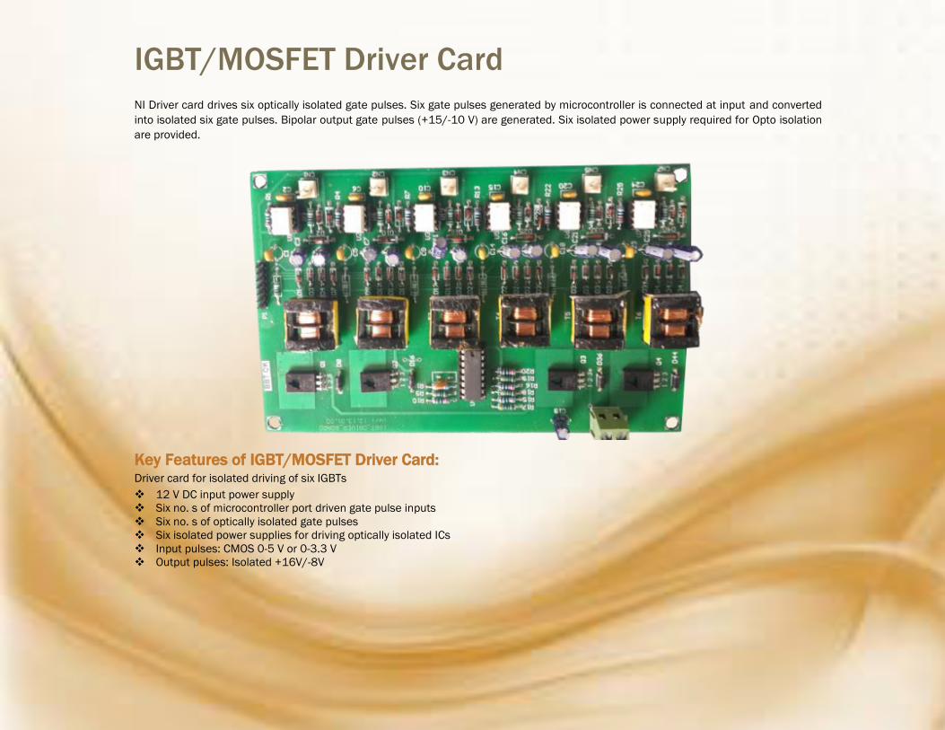
IGBT/MOSFET Driver Card
NI Driver card drives six optically isolated gate pulses. Six gate pulses generated by microcontroller is connected at input and converted
into isolated six gate pulses. Bipolar output gate pulses (+15/-10 V) are generated. Six isolated power supply required for Opto isolation
are provided.
Key Features of IGBT/MOSFET Driver Card: Driver card for isolated driving of six IGBTs
12 V DC input power supply
Six no. s of microcontroller port driven gate pulse inputs
Six no. s of optically isolated gate pulses
Six isolated power supplies for driving optically isolated ICs
Input pulses: CMOS 0-5 V or 0-3.3 V
Output pulses: Isolated +16V/-8V

Single Phase Sensor Card
Single Phase Sensor card is developed to sense 01 AC Voltage, 01 AC Current
Signals. It is possible to add offset voltage for interfacing sensed signal with unipolar
ADC, Amplitude calibration is also possible. More then Two Single Phase Sensor cards
can be cascaded with each other, therefore increasing number of channels available.
Key Features of Single Phase Sensor Card: Single Phase Sensor card with following features:
One AC/DC voltage measurement
o Isolated measurement
o One voltage sensing using Hall-Voltage Sensor
o 0-3V (peak-peak) output
o Unipolar output with DC offset
o Suitable for interfacing with unipolar ADC channel
One AC/DC current measurement
o Isolated measurement
o One current sensing using Hall-Current Sensor
o 0-3V (peak-peak) output
o Unipolar output with DC offset
o Suitable for interfacing with unipolar ADC channel
Auxiliary power supply and connectors for power connections.
Two or more cards can be cascaded together with expansion connectors when
necessary.
Hall-current Sensor Specifications
o Vout Output voltage at Ir, TA=25 : 4V
o Output Impedance <150 ohm
o Load Resistor >10Kohm
o Vcc Supply Voltage: ±15V ±5%
o Current Consumption <20mA
o Accuracy at Ir, TA=25 (without offset) <1%
o Linearity from 0 to Ir, TA=25 <1%
o Frequency Bandwidth (-3dB) 50KHz
Hall-voltage Sensor Specifications
o Primary Voltage Measuring Range
o VPN(V): 10~500
o Primary nominal rms current: 10 mA
o Primary current, measuring range: 0~±14 mA
o Secondary nominal rms current: 25 mA
o Conversion ratio 2500:1000
o Vc Supply voltage ±12~15 V, (±5%)
o Ic Current consumption 10(@±15V) +Is mA
o RMS voltage for AC insulation test, 50 HZ 1 min 2.5 kV
o Creepage distance: 19.5 mm
o Overall accuracy @IPN, TA=25 @±12~15V: ±0.9 %, @±15V (±5%):
±0.8 %
o Linearity error <0.2 %

Three Phase Sensor Card (V1) First version of NI Sensor card is developed to sense 03 AC Voltage, 03 AC Current Signals. Also, 01 DC Current and 01 DC Voltage measurement is possible. It is possible to
add offset voltage for interfacing sensed signal with unipolar ADC, Amplitude calibration is also possible. Quadrature Encoder Interface section is provided. Zero crossing
detection is also provided. Hall Sensor or Encoder Interfacing for Three channels to connect either three lines of hall sensor or A-B-Z pulses of encoder is provided.
Key Features: AC voltage measurement
o Isolated measurement
o Three voltage sensing using PT (Potential Transformer)
o Per phase 230 V, 50 Hz voltage to 0-3V (peak-peak) output
o Unipolar output with DC offset
o Suitable for interfacing with unipolar ADC channel
AC current measurement, 0-3V unipolar output
o Isolated measurement
o Three current sensing using CT (Current Transformer 1200:1)
o 5 A, 50 Hz current to 0-3V (peak-peak) output
o Unipolar output with DC offset
o Suitable for interfacing with unipolar ADC channel
One DC voltage measurement
o Non-isolated measurement
o Resistive potential divider for dc voltage sensing
o 600 V to 0-3V output
One DC current measurement
o Isolated measurement
o ACS 712 hall current sensor
o 66 to 185 mV/A output sensitivity
Hall Sensor or Encoder interfacing
o Three channels to connect either three lines of hall sensor or A-B-Z pulses of encoder
o Internal pull up and wave shaping for microcontroller interfacing
Auxiliary power supply and connectors for power connections.

Three Phase Four Wire Sensor Card (V2)
Sensor card V2 is Modified Version of Sensor Card V1 with extra features such as Neutral Current sensing, Zero Current detection and Over Current protection Circuit. It senses
04 AC voltage and 04 AC current signals, with Offset addition and Amplitude control port. 01 DC Current and 01 DC Voltage measurement is also possible. Zero crossing
detection is also provided. Hall Sensor or Encoder Interfacing to connect either three lines of hall sensor or A-B-Z pulses of encoder is provided.
Key Features: Sensor card with following features:
AC voltage measurement
o Isolated measurement
o Four voltage sensing (three phases and neutral) using PT (Potential Transformer)
o Per phase 230 V, 50 Hz voltage to 0-3V (peak-peak) output
o ZCD (Zero Cross Detection) of all three voltages
o Unipolar output with DC offset
o Suitable for interfacing with unipolar ADC channel
AC current measurement, 0-3V unipolar output
o Isolated measurement
o Four current sensing (three line current and neutral) using CT (Current Transformer 1200:1)
o 5 A, 50 Hz current to 0-3V (peak-peak) output
o ZCD (Zero Cross Detection) of all three sensed currents
o Unipolar output with DC offset
o Suitable for interfacing with unipolar ADC channel
One DC voltage measurement
o Non-isolated measurement
o Resistive potential divider for dc voltage sensing
o 600 V to 0-3V output
One DC current measurement
o Isolated measurement
o ACS 712 hall current sensor
o 66 to 185 mV/A output sensitivity
Speed Sensor interfacing
o Three channels to connect three lines of hall sensor
o Three channels to connect A-B-Z pulses of encoder
o Internal pull up and wave shaping for microcontroller interfacing
Comparator for over current detection.
Auxiliary power supply and connectors for power connections.
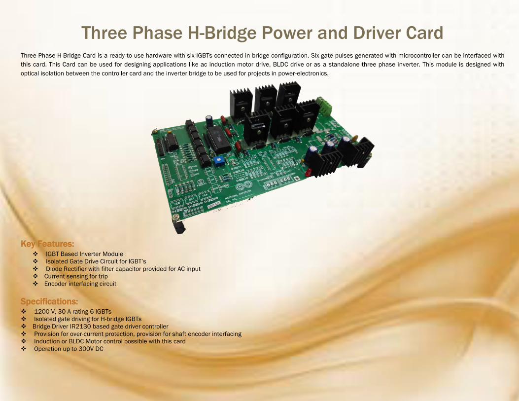
Three Phase H-Bridge Power and Driver Card Three Phase H-Bridge Card is a ready to use hardware with six IGBTs connected in bridge configuration. Six gate pulses generated with microcontroller can be interfaced with
this card. This Card can be used for designing applications like ac induction motor drive, BLDC drive or as a standalone three phase inverter. This module is designed with
optical isolation between the controller card and the inverter bridge to be used for projects in power-electronics.
Key Features: IGBT Based Inverter Module
Isolated Gate Drive Circuit for IGBT’s
Diode Rectifier with filter capacitor provided for AC input
Current sensing for trip
Encoder interfacing circuit
Specifications: 1200 V, 30 A rating 6 IGBTs
Isolated gate driving for H-bridge IGBTs
Bridge Driver IR2130 based gate driver controller
Provision for over-current protection, provision for shaft encoder interfacing
Induction or BLDC Motor control possible with this card
Operation up to 300V DC
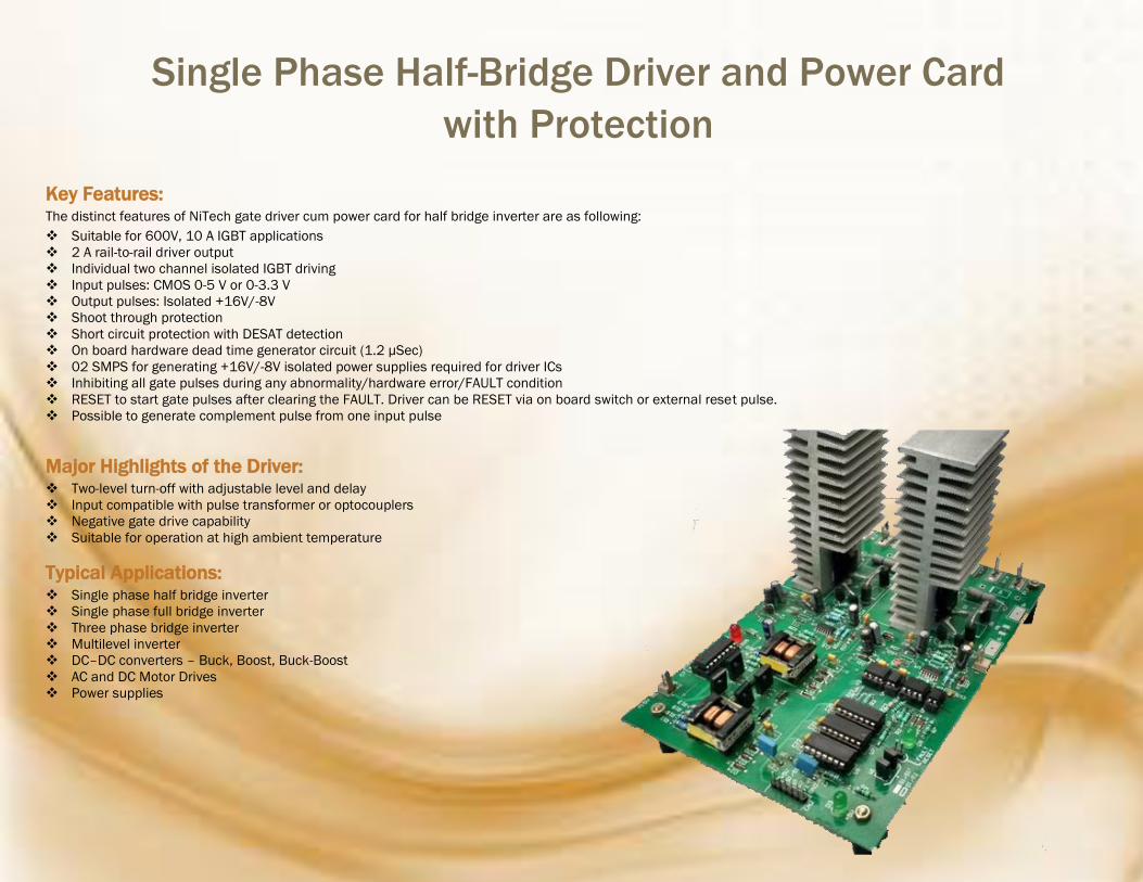
Single Phase Half-Bridge Driver and Power Card
with Protection
Key Features: The distinct features of NiTech gate driver cum power card for half bridge inverter are as following:
Suitable for 600V, 10 A IGBT applications
2 A rail-to-rail driver output
Individual two channel isolated IGBT driving
Input pulses: CMOS 0-5 V or 0-3.3 V
Output pulses: Isolated +16V/-8V
Shoot through protection
Short circuit protection with DESAT detection
On board hardware dead time generator circuit (1.2 µSec)
02 SMPS for generating +16V/-8V isolated power supplies required for driver ICs
Inhibiting all gate pulses during any abnormality/hardware error/FAULT condition
RESET to start gate pulses after clearing the FAULT. Driver can be RESET via on board switch or external reset pulse.
Possible to generate complement pulse from one input pulse
Major Highlights of the Driver: Two-level turn-off with adjustable level and delay
Input compatible with pulse transformer or optocouplers
Negative gate drive capability
Suitable for operation at high ambient temperature
Typical Applications: Single phase half bridge inverter
Single phase full bridge inverter
Three phase bridge inverter
Multilevel inverter
DC–DC converters – Buck, Boost, Buck-Boost
AC and DC Motor Drives
Power supplies

Three Phase Driver and Power Card with Protection
Key Features:
The distinct features of Three Phase Driver card with Protection are as following:
Suitable for 600V / 1200V, 25 A IGBTs
2 A rail-to-rail output
Individual six channel isolated IGBT driving
Input pulses: CMOS 0-5 V or 0-3.3 V (Active high pulse)
Output pulses: Isolated +16V/-8V
Shoot through protection
Short circuit protection with DESAT-detection
On board hardware dead time generator circuit (1 uSec)
06 SMPS for generating +16V/-8V isolated power supplies required for driver IC
Inhibiting all gate pulses during any abnormality/hardware error/FAULT condition
RESET to start gate pulses after clearing the FAULT. Driver can be RESET via on board switch or external reset pulse.
06 individual Fault and Ready indications
Possible to generate 03 complement pulses from three input pulses
On board test points are provided for signals troubleshooting
Major Highlights of the Driver: Coreless transformer based isolated driver
Galvanic Insulation
Integrated protection features
Suitable for operation at high ambient temperature
Typical Applications: AC and DC Motor Drives
High Voltage AC/DC, DC/DC-Converter
Power quality Converters – STATCOM, Active Filter
Power supplies- Stabilizer
UPS-Systems & Welding

Rapid Prototype Development Environment for
Power Electronic System
Microcontroller based rapid prototype development environment consists of the
following modules:
ARM Cortex M4 32-bit Microcontroller
Three Phase voltage current Sensor card
DC voltage current Sensor card
Block Diagram of Power Electronics System
Development Environment:
Specifications of Power Electronic System Development
Environment:
32-bit ARM Cortex-M4 Microcontroller (STM32F407VGT6) running at 168
MHz and providing peak throughput of 210 MIPs
Maximum Input: DC link 600 V/10 A, Output: 400V/10 A
Three phase 1200 V, 30 A IGBT power module with appropriate heat-sink
and snubber
Recommended switching frequency of the inverter 20 kHz
Isolated driving circuit for 06 gate pulses of IGBTs
IGBTs with desaturation protection against overload and short-circuit
Individual Indication of READY and FAULT with a provision to latch driver
output and reset with RESET button
Fault output for communicating FAULT status to the Microcontroller
Sensing Card for Three AC output voltages, Three AC output currents, One
DC current and One DC voltage
The distinct features of individual cards are detailed below.
(i) ARM Cortex M4 32-BIT Microcontroller: 32-bit ARM Cortex-M4F core, 1 MB Flash, 192 KB RAM in an LQFP100
package
Microcontroller running at 168 MHz, providing peak throughput 210 MIPs
For programming and debugging onboard ST-LINK/V2
Board power supply: through USB bus or from an external 12V AC supply
GPIO ports are routed to header on mother board for easy connection
o 8 General purpose input lines, 8 General purpose output lines
o 16x2 LCD interface, 5 keys interface.
o 3 high speed digital outputs and 2 High speed digital input lines.
o 6 PWM outputs, 3 QEI inputs.
o SPI bus for SPI slave interface.
o 9 Analog inputs
o 2 Analog Universal outputs
o 9-pin D-type connector for RS232 interfaces.
All pins have 5V tolerance.
(ii) Three Phase voltage current Sensor card: 03 AC voltage measurement
03 AC current measurement
Isolated measurement
Output restricted to 0-3V (peak-peak)
Unipolar output with DC offset
Suitable for interfacing with unipolar ADC channel
(iii) DC voltage current Sensor card One DC voltage measurement
One DC current measurement
Isolated measurement
Output restricted to 0-3V below unipolar ADC reference
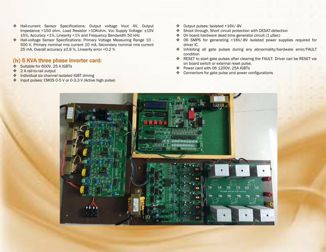
Hall-current Sensor Specifications: Output voltage Vout 4V, Output
Impedance <150 ohm, Load Resistor >10Kohm, Vcc Supply Voltage: ±15V
±5%, Accuracy <1%, Linearity <1% and Frequency Bandwidth 50 kHz
Hall-voltage Sensor Specifications: Primary Voltage Measuring Range 10 -
500 V, Primary nominal rms current 10 mA, Secondary nominal rms current
25 mA, Overall accuracy ±0.9 %, Linearity error <0.2 %
(iv) 5 KVA three phase inverter card: Suitable for 600V, 25 A IGBTs
2 A rail-to-rail output
Individual six channel isolated IGBT driving
Input pulses: CMOS 0-5 V or 0-3.3 V (Active high pulse)
Output pulses: Isolated +16V/-8V
Shoot through, Short circuit protection with DESAT-detection
On board hardware dead time generator circuit (1 µSec)
06 SMPS for generating +16V/-8V isolated power supplies required for
driver IC
Inhibiting all gate pulses during any abnormality/hardware error/FAULT
condition
RESET to start gate pulses after clearing the FAULT. Driver can be RESET via
on board switch or external reset pulse.
Power card with 06 1200V, 25A IGBTs
Connectors for gate pulse and power configurations
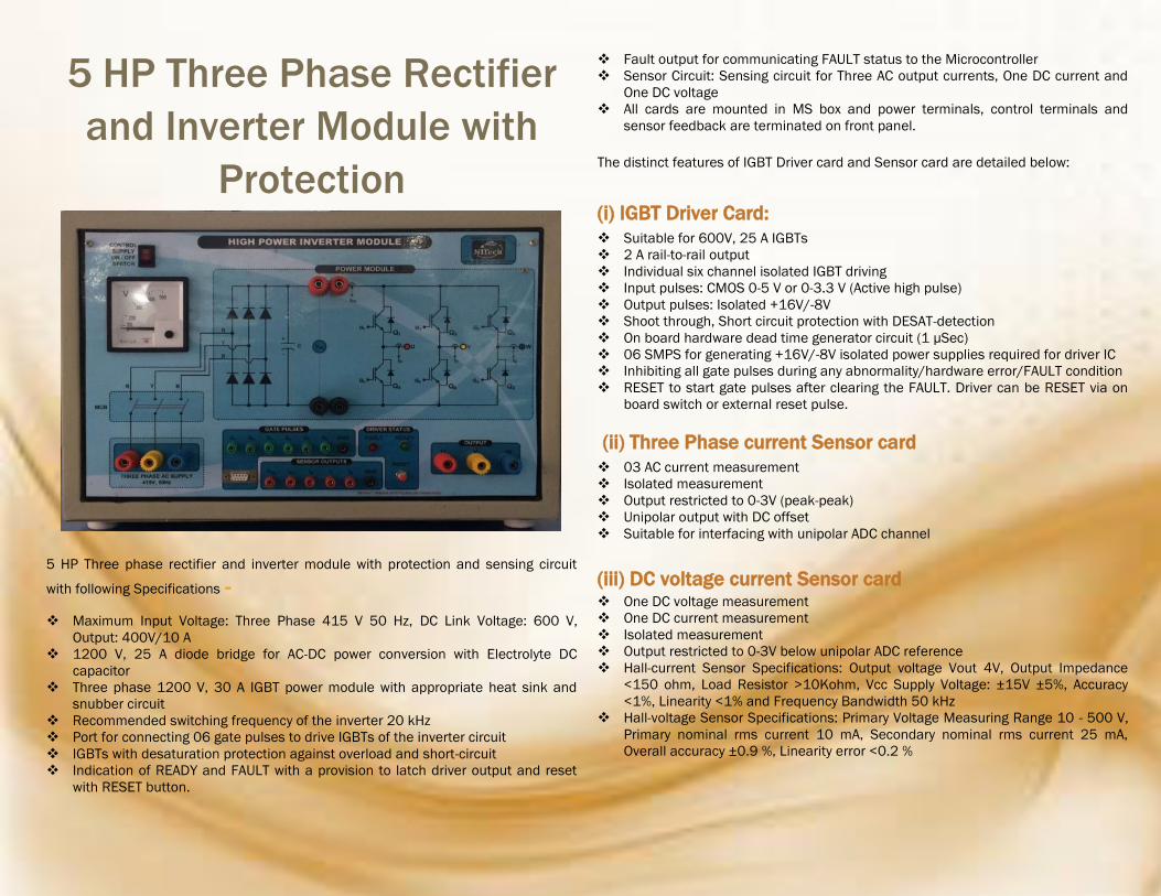
5 HP Three Phase Rectifier
and Inverter Module with
Protection
5 HP Three phase rectifier and inverter module with protection and sensing circuit
with following Specifications -
Maximum Input Voltage: Three Phase 415 V 50 Hz, DC Link Voltage: 600 V,
Output: 400V/10 A
1200 V, 25 A diode bridge for AC-DC power conversion with Electrolyte DC
capacitor
Three phase 1200 V, 30 A IGBT power module with appropriate heat sink and
snubber circuit
Recommended switching frequency of the inverter 20 kHz
Port for connecting 06 gate pulses to drive IGBTs of the inverter circuit
IGBTs with desaturation protection against overload and short-circuit
Indication of READY and FAULT with a provision to latch driver output and reset
with RESET button.
Fault output for communicating FAULT status to the Microcontroller
Sensor Circuit: Sensing circuit for Three AC output currents, One DC current and
One DC voltage
All cards are mounted in MS box and power terminals, control terminals and
sensor feedback are terminated on front panel.
The distinct features of IGBT Driver card and Sensor card are detailed below:
(i) IGBT Driver Card:
Suitable for 600V, 25 A IGBTs
2 A rail-to-rail output
Individual six channel isolated IGBT driving
Input pulses: CMOS 0-5 V or 0-3.3 V (Active high pulse)
Output pulses: Isolated +16V/-8V
Shoot through, Short circuit protection with DESAT-detection
On board hardware dead time generator circuit (1 µSec)
06 SMPS for generating +16V/-8V isolated power supplies required for driver IC
Inhibiting all gate pulses during any abnormality/hardware error/FAULT condition
RESET to start gate pulses after clearing the FAULT. Driver can be RESET via on
board switch or external reset pulse.
(ii) Three Phase current Sensor card
03 AC current measurement
Isolated measurement
Output restricted to 0-3V (peak-peak)
Unipolar output with DC offset
Suitable for interfacing with unipolar ADC channel
(iii) DC voltage current Sensor card One DC voltage measurement
One DC current measurement
Isolated measurement
Output restricted to 0-3V below unipolar ADC reference
Hall-current Sensor Specifications: Output voltage Vout 4V, Output Impedance
<150 ohm, Load Resistor >10Kohm, Vcc Supply Voltage: ±15V ±5%, Accuracy
<1%, Linearity <1% and Frequency Bandwidth 50 kHz
Hall-voltage Sensor Specifications: Primary Voltage Measuring Range 10 - 500 V,
Primary nominal rms current 10 mA, Secondary nominal rms current 25 mA,
Overall accuracy ±0.9 %, Linearity error <0.2 %