abs rules for materials and welding
TRANSCRIPT

P a r t 2 : R u l e s f o r M a t e r i a l s a n d W e l d i n g
RULES FOR
MATERIALS AND WELDING 2010
PART 2
American Bureau of Shipping Incorporated by Act of Legislature of the State of New York 1862
Copyright © 2009 American Bureau of Shipping ABS Plaza 16855 Northchase Drive Houston, TX 77060 USA

ii ABS RULES FOR MATERIALS AND WELDING . 2010
R u l e C h a n g e N o t i c e ( 2 0 0 9 )
Rule Change Notice (2010) The effective date of each technical change since 1993 is shown in parenthesis at the end of the subsection/paragraph titles within the text of each Part. This date is based on the date of purchase order of the materials. Unless a particular date and month are shown, the years in parentheses refer to the following effective dates:
(2000) and after 1 January 2000 (and subsequent years) (1996) 9 May 1996 (1999) 12 May 1999 (1995) 15 May 1995 (1998) 13 May 1998 (1994) 9 May 1994 (1997) 19 May 1997 (1993) 11 May 1993
Listing by Effective Dates of Changes from the 2009 Rules
EFFECTIVE DATE 1 January 2010 – shown as (2010) (based on the date of purchase order of the materials)
Part/Para. No. Title/Subject Status/Remarks 2-1-1/1.2.1 <No Title> To align the requirements with IACS UR W11, Rev. 7 and Appendices
2-A4-1 and 2-A4-2 of the ABS Rules for Materials and Welding.
2-2-1/3 Materials for Anchors To include Charpy Impact testing requirements for all cast anchors.
2-2-1/5.9 Repairs To require that anchor manufacturers maintain a record of weld repairs to anchor castings or forgings. To reference 2-2-1/7.3.7, highlighting that repairs of cracks detected after drop test or during hammering test is not permitted.
2-2-1/Table 1 Applicable Test Programs for Each Product Form
To include Charpy Impact testing requirements for all cast anchors.
2-2-1/Table 2 Product test Requirements for Program A and B
To require drop testing for Program B
2-3-7/1.15 Rectification of Defective Forgings To clarify that welders or welding operators are required to be qualified for the repair welding of forgings.
2-3-9/15.7 Welded Repair To clarify that welders or welding operators are required to be qualified for the repair welding of castings.
2-4-4/5.11 Peening To distinguish between peening for distortion control and peening for fatigue life enhancement.
2-4-4/5.12 (New)
Weld Profiling To provide criteria regarding weld profiling for fatigue life enhancement.
2-4-4/5.21 (New)
Fillet Weld Ends To provide clarification regarding wrapping of fillet weld ends.
2-4-2/1.3 Welding Approval To clarify that filler metals other than electrodes also need to be approved by the Surveyor.
2-4-3/11.3 Qualification Tests To permit qualification of welders to recognized standards, such as ISO 9606-1, AWS B2.1, AWS D1.1, NavSea Technical Publication S9074-AQ-GIB-010/248, ASME Section IX, or other equivalent.
2-4-3/Table 1 Welder Qualification Tests To align the requirements with current welder qualification test practices.
2-4-3/Figure 13 Orientation and Location of Charpy V-notch Specimens for Weld and Heat Affected Zone Properties
To align the requirements with IACS UR W28 Annex A.
2-A2-1/9.3.1 Deposited Metal Test and Diffusible Hydrogen Test
To clarify when buttering may be applied.
2-A2-1/9.3.2 Butt Weld Test and Fillet Weld Test To align the requirements with IACS UR W17 and to add equivalent grades from other class societies.

ABS RULES FOR MATERIALS AND WELDING . 2010 iii
Part/Para. No. Title/Subject Status/Remarks 2-A2-1/29.1.2 Uprating To clarify that fillet testing is to be conducted for uprating to YQ
grades of SMAW electrodes.
Appendix 4 Procedure for the Approval of Manufacturers of Hull Structural Steel
To align the requirements with IACS UR W11 Rev. 7.
2-A7-2/Table 1 Crankshaft Forgings –Allowable Number and Size of Indications in a Reference Area of 225 cm2
To align the table with 4-3-2/3.7.3 of the ABS Rules for Building and Classing Steel Vessels.
2-A7-2/Table 2 Steel Forgings Excluding Crankshaft Forgings - Allowable Number and Size of Indications in a Reference Area of 225 cm2
To align the table with 4-3-2/3.7.3 of the ABS Rules for Building and Classing Steel Vessels.

iv ABS RULES FOR MATERIALS AND WELDING . 2010
P A R T F o r e w o r d
2
Foreword For the 1996 edition, the “Rules for Building and Classing Steel Vessels – Part 2: Materials and Welding” was re-titled “Rule Requirements for Materials and Welding (Part 2).” The purpose of this generic title was to emphasize the common applicability of the material and welding requirements in “Part 2” to ABS-classed vessels, other marine structures and their associated machinery, and thereby make “Part 2” more readily a common “Part” of the various ABS Rules and Guides, as appropriate.
Accordingly, the subject booklet, Rules for Materials and Welding (Part 2), is to be considered, for example, as being applicable and comprising a “Part” of the following ABS Rules and Guides:
- Rules for Building and Classing Steel Vessels
- Rules for Building and Classing Steel Vessels Under 90 Meters (295 Feet) in Length
- Rules for Building and Classing Steel Vessels for Service on Rivers and Intracoastal Waterways
- Rules for Building and Classing Mobile Offshore Drilling Units
- Rules for Building and Classing Steel Barges
- Guide for Building and Classing High Speed Craft
- Guide for Building and Classing High Speed Naval Craft
- Guide for Building and Classing Liftboats
- Guide for Building and Classing Floating Production Installations
In the 2002 edition, Section 4, “Piping” was added to Part 2, Chapter 4, “Welding and Fabrication”. This Section is applicable only to piping to be installed on vessels to be built in accordance with the ABS Rules for Building and Classing Steel Vessels.
In the 2004 edition, Part 2 was reorganized to incorporate the new divisions “Rules for Testing and Certification of Materials,” comprised of Chapters 1, 2 and 3 and Appendices 1, 4, 5, 6 and 7, and “Rules for Welding and Fabrication,” comprised of Chapter 4 and Appendices 2 and 3. This reorganization was purely an editorial change intended to clarify the requirements for the materials themselves and for construction, respectively, and does not contain any technical changes.

ABS RULES FOR MATERIALS AND WELDING . 2010 v
P A R T T a b l e o f C o n t e n t s
2 Rules for Materials and Welding
CONTENTS
Rules for Testing and Certification of Materials CHAPTER 1 Materials for Hull Construction............................................................. 1
Section 1 General Requirements...........................................................6 Section 2 Ordinary-strength Hull Structural Steel ................................20 Section 3 Higher-strength Hull Structural Steel ...................................30 Section 4 Low Temperature Materials .................................................37 Section 5 Hull Steel Castings...............................................................39 Section 6 Hull Steel Forgings...............................................................44
CHAPTER 2 Equipment............................................................................................. 49
Section 1 Anchors................................................................................52 Section 2 Anchor Chain .......................................................................63 Section 3 Rolled Steel Bars for Chain, Cast and Forged Materials
for Accessories and Materials for Studs ..............................77 CHAPTER 3 Materials for Machinery, Boilers, Pressure Vessels, and Piping ..... 81
Section 1 General Requirements.........................................................96 Section 2 Steel Plates for Machinery, Boilers and Pressure
Vessels ..............................................................................102 Section 3 Seamless Forged-steel Drums ..........................................111 Section 4 Seamless-steel Pressure Vessels .....................................112 Section 5 Boiler and Superheater Tubes...........................................113 Section 6 Boiler Rivet and Staybolt Steel and Rivets ........................126 Section 7 Steel Machinery Forgings ..................................................128 Section 8 Hot-rolled Steel Bars for Machinery...................................155 Section 9 Steel Castings for Machinery, Boilers and Pressure
Vessels ..............................................................................156 Section 10 Ductile (Nodular) Iron Castings..........................................161 Section 11 Gray-iron Castings .............................................................169 Section 12 Steel Piping........................................................................174 Section 13 Piping, Valves and Fittings for Low-Temperature
Service [Below -18°C (0°F)]...............................................191 Section 14 Bronze Castings.................................................................194

vi ABS RULES FOR MATERIALS AND WELDING . 2010
Section 15 Austenitic Stainless Steel Propeller Castings....................198 Section 16 Seamless Copper Piping ...................................................201 Section 17 Seamless Red-brass Piping ..............................................205 Section 18 Seamless Copper Tube .....................................................208 Section 19 Condenser and Heat Exchanger Tube ..............................211 Section 20 Copper-Nickel Tube and Pipe............................................217 Section 21 Monel Pipe and Tube.........................................................223
APPENDIX 1 List of Destructive and Nondestructive Tests Required in
Part 2, Chapters 1, 2 and 3 and Responsibility for Verifying.......... 291 APPENDIX 4 Procedure for the Approval of Manufacturers of Hull Structural
Steel..................................................................................................... 334 Section 1 Procedure for the Approval of Manufacturers of
Semi-finished Products for Hull Structural Steel................336 Section 2 Procedure for the Approval of Manufacturers of Rolled
Hull Structural Steel ...........................................................341 APPENDIX 5 Procedure for the Approval of Manufacturers of Hull Structural
Steels Intended for Welding with High Heat Input........................... 349 APPENDIX 6 Guide for Nondestructive Examination of Marine Steel
Castings .............................................................................................. 354 Section 1 General ..............................................................................356 Section 2 Surface Inspection .............................................................357 Section 3 Volumetric Inspection.........................................................362 Annex 1 General Location for the Type of Nondestructive
Examinations of Typical Hull Steel Castings .....................365 APPENDIX 7 Guide for Nondestructive Examination of Hull and Machinery
Steel Forgings .................................................................................... 371 Section 1 General ..............................................................................373 Section 2 Surface Inspection .............................................................374 Section 3 Volumetric Inspection.........................................................383
Rules for Welding and Fabrication CHAPTER 4 Welding and Fabrication.................................................................... 230
Section 1 Hull Construction................................................................235 Section 2 Boilers, Unfired Pressure Vessels, Piping and
Engineering Structures ......................................................241 Section 3 Weld Tests .........................................................................263 Section 4 Piping .................................................................................284

ABS RULES FOR MATERIALS AND WELDING . 2010 vii
APPENDIX 2 Requirements for the Approval of Filler Metals............................... 295 Section 1 General ..............................................................................299 Section 2 Electrodes for Shielded Metal Arc Welding .......................310 Section 3 Wire-Flux Combinations for Submerged Arc Welding .......317 Section 4 Wire and Wire Gas Combinations for Gas Metal Arc
Welding and Flux Cored Wires for Flux Cored Arc Welding ..............................................................................325
APPENDIX 3 Application of Filler Metals to ABS Steels ....................................... 333


ABS RULES FOR TESTING AND CERTIFICATION OF MATERIALS . 2010 1
P A R T C h a p t e r 1 : M a t e r i a l s f o r H u l l C o n s t r u c t i o n
2 Rules for Testing and Certification of Materials
C H A P T E R 1 Materials for Hull Construction
CONTENTS SECTION 1 General Requirements........................................................................... 6
1 Testing and Inspection........................................................................6 1.1 General............................................................................................6 1.2 Manufacturer Approval ....................................................................6 1.3 Test and Test Data..........................................................................6 1.5 Certification on the Basis of the ABS Quality Assurance
Program for Rolled Products ...........................................................7 1.7 Rejection of Previously Accepted Material ......................................7 1.9 Calibrated Testing Machines ...........................................................7 1.11 Structural Pipe.................................................................................7 1.13 ASTM References ...........................................................................7
3 Defects ................................................................................................7 5 Identification of Materials ....................................................................7 7 Manufacturer’s Certificates .................................................................8
7.1 Form of Certificate...........................................................................8 7.3 Other Certificates ............................................................................8
9 Marking and Retests ...........................................................................8 9.1 Identification of Specimens..............................................................8 9.3 Defects in Specimens......................................................................8 9.5 Retests ............................................................................................8 9.7 Rejected Material ............................................................................8
11 Standard Test Specimens...................................................................9 11.1 General............................................................................................9 11.3 Test Specimens Orientation ............................................................9 11.5 Tension Test Specimens, Plates and Shapes ................................. 9 11.7 Tension Test Specimens for Castings (other than Gray Cast
Iron) and Forgings ...........................................................................9 11.9 Bend Test Specimens, Castings and Forgings................................ 9 11.11 Impact Test Specimens...................................................................9 11.13 Tolerances.......................................................................................9
13 Definition and Determination of Yield Point and Yield Strength .......10 13.1 Yield Point .....................................................................................10 13.3 Yield Strength................................................................................10 13.5 Tensile Strength ............................................................................10
14 Elongation .........................................................................................10
2 ABS RULES FOR TESTING AND CERTIFICATION OF MATERIALS . 2010
15 Permissible Variations in Dimensions...............................................11 15.1 Scope ............................................................................................11 15.3 Plates.............................................................................................11 15.5 Shapes and Bars ...........................................................................11
16 Rolled Plates over 100 mm (4 in.) Thick...........................................11 17 Steel Plates and Wide Flats with Specified Minimum Through
Thickness Properties (“Z” Quality) ....................................................15 17.1 Sampling........................................................................................15 17.3 Number of Tensile Test Specimens...............................................16 17.5 Tensile Test Specimen Dimensions...............................................16 17.7 Tensile Test Results ......................................................................16 17.9 Retests ..........................................................................................16 17.11 Ultrasonic Inspection .....................................................................17 17.13 Marking..........................................................................................17 17.15 Certification....................................................................................17
19 Formed Materials ..............................................................................17 21 Ultrasonic Examination of Plate Material ..........................................17 23 Fracture Toughness Testing.............................................................18 TABLE 1 Batch Size Depending Upon Product and Sulfur Content ......15 TABLE 2 Reduction of Area Acceptance Values ...................................16 FIGURE 1 Standard Tension Test Specimen...........................................12 FIGURE 2 Standard Round Tension Test Specimen with 50 mm (2 in.)
Gauge Length .........................................................................13 FIGURE 3 Charpy V-notch Impact Test Specimens ................................14 FIGURE 4 Plate and Wide Flat Sampling Position...................................16 FIGURE 5 Diagram Showing Acceptance/Rejection and Retest
Criteria.....................................................................................17 SECTION 2 Ordinary-strength Hull Structural Steel.............................................. 20
1 Ordinary-strength Hull Structural Steel .............................................20 3 Process of Manufacture ....................................................................20
3.1 Plates Produced from Coils ...........................................................20
5 Chemical Composition ......................................................................20 5.1 Ladle Analysis ...............................................................................20 5.3 Product Analysis ............................................................................20 5.5 Special Compositions ....................................................................20 5.7 Fine Grain Practice ........................................................................20
7 Condition of Supply...........................................................................21 7.1 As Rolled – AR ..............................................................................21 7.3 Heat Treatment..............................................................................21 7.5 Controlled Manufacturing Process.................................................21 7.7 Quenching and Tempering – QT ...................................................22
9 Tensile Properties .............................................................................22 9.1 Required Tensile Properties ..........................................................22 9.3 Tension Test Specimens ...............................................................22

ABS RULES FOR TESTING AND CERTIFICATION OF MATERIALS . 2010 3
9.5 Exceptions.....................................................................................22 9.7 <No Text>......................................................................................22 9.9 Omission of Elongation Requirements .......................................... 22 9.11 Retests ..........................................................................................23 9.13 Unsatisfactory Tests......................................................................23
11 Impact Properties..............................................................................23 11.1 Impact Tests..................................................................................23 11.3 Impact Test Frequency..................................................................23 11.5 Initial Test Requirements...............................................................23 11.7 Retests ..........................................................................................24 11.9 Unsatisfactory Tests......................................................................24 11.11 Thin Plates ....................................................................................24
13 Marking .............................................................................................24 13.1 Stamped or Stenciled Material ......................................................24 13.3 Coils, Lifts and Bundles.................................................................24 13.5 Flanging-quality Identification ........................................................24 13.7 Special Stamping and Marking......................................................24 13.9 Special Impact Testing ..................................................................25 13.11 Steel with Improved Through Thickness Properties ...................... 25 13.13 Steel with Ultrasonic Examination ................................................. 25 13.15 Shipping Procedure.......................................................................25 13.17 Steel at Secondary Sources .......................................................... 25
15 Surface Finish ...................................................................................25 15.1 Surface Examination .....................................................................25 15.3 Treatment of Surface Defects – Plates.......................................... 25 15.5 Treatment of Surface Defects – Shapes ....................................... 26 15.7 Bar-stock Repairs..........................................................................26 15.9 Rivet Steel and Rivets ...................................................................26
TABLE 1 Chemical Properties of Ordinary Strength Hull Structural
Steel 100 mm (4.0 in.) and Under...........................................27 TABLE 2 Tensile Properties of Ordinary Strength Hull Structural
Steel 100 mm (4.0 in.) and Under...........................................28 TABLE 3 Elongation Requirements for Alternative B Specimen............28 TABLE 4 Impact Properties of Ordinary-Strength Hull Structural
Steel 100 mm (4.0 in.) and Under...........................................28 TABLE 5 Condition of Supply and Frequency of Impact Tests
Ordinary Strength Hull Structural Steel...................................29 SECTION 3 Higher-strength Hull Structural Steel ................................................. 30
1 Higher-strength Hull Structural Steel ................................................30 3 General .............................................................................................30 5 Fine Grain Practice ...........................................................................30 7 Additional Requirements of TMCP Steel ..........................................31
7.1 Carbon Equivalent .........................................................................31 7.3 Cold Cracking Susceptibility .......................................................... 31

4 ABS RULES FOR TESTING AND CERTIFICATION OF MATERIALS . 2010
TABLE 1 Chemical Properties of Higher-strength Hull Structural Steel 100 mm (4.0 in.) and Under...........................................32
TABLE 2 Tensile Properties of Higher-strength Hull Structural Steel 100 mm (4.0 in.) and Under...........................................33
TABLE 3 Elongation Requirements for Alternative B Specimen............33 TABLE 4 Impact Properties of Higher-strength Steel 100 mm (4.0 in.)
and Under ...............................................................................34 TABLE 5 Condition of Supply and Frequency of Impact Tests –
Higher-strength Hull Structural Steel ......................................35 TABLE 6 Carbon Equivalent for Higher-strength Hull Structural
Steel 100 mm (4.0 in.) and Under Produced by TMCP ..........36 SECTION 4 Low Temperature Materials ................................................................. 37
1 General .............................................................................................37 3 Marking .............................................................................................37 5 Toughness Tests ..............................................................................37
5.1 Charpy V-notch..............................................................................37 5.3 Drop-weight Test ...........................................................................37
7 Service Temperature 0°C (32°F) or Above.......................................37 9 Service Temperature at or Above -55°C (-67°F) up to
0°C (32°F) .........................................................................................37 11 Service Temperature at or Above -196°C (-320°F) up to
-55°C (-67°F)....................................................................................38 13 Service Temperatures below -196°C (-320°F) .................................38
SECTION 5 Hull Steel Castings............................................................................... 39
1 Process of Manufacture ....................................................................39 1.1 General..........................................................................................39 1.3 Chemical Composition...................................................................39
3 Marking and Retests .........................................................................40 3.1 Marking..........................................................................................40 3.3 Retests ..........................................................................................40
5 Heat Treatment .................................................................................40 7 Mechanical Properties ......................................................................41
7.1 Ordinary Grade Castings ...............................................................41 7.3 Special Grade Castings .................................................................41
9 Test Specimens ................................................................................41 9.1 Material Coupons...........................................................................41 9.3 Separately Cast Coupons..............................................................42
11 Number of Tests ...............................................................................42 13 Inspection and Repair .......................................................................42
13.1 General..........................................................................................42 13.3 Minor Defects ................................................................................42 13.5 Major Defects ................................................................................42 13.7 Welded Repair ...............................................................................42 13.9 Post Weld Repair Heat Treatment .................................................43 13.11 Nondestructive Testing ..................................................................43
15 Certification .......................................................................................43
ABS RULES FOR TESTING AND CERTIFICATION OF MATERIALS . 2010 5
SECTION 6 Hull Steel Forgings .............................................................................. 44 1 Process of Manufacture ....................................................................44
1.1 General..........................................................................................44 1.3 Degree of Reduction .....................................................................44 1.5 Discard ..........................................................................................44 1.7 Chemical Composition ..................................................................45
3 Marking and Retests .........................................................................45 3.1 Marking..........................................................................................45 3.3 Retests ..........................................................................................45
5 Heat Treatment .................................................................................45 5.1 General..........................................................................................45 5.3 Cooling Prior to Heat Treatment.................................................... 46 5.5 Annealing ......................................................................................46 5.7 Normalizing ...................................................................................46 5.9 Tempering .....................................................................................46
7 Tensile Properties .............................................................................46 9 Test Specimens ................................................................................46
9.1 Location and Orientation of Specimens......................................... 46 9.3 Hollow-drilled Specimens .............................................................. 47 9.5 Small Forgings .............................................................................. 47 9.7 Specimen Identification .................................................................47
11 Number of Tests ...............................................................................47 11.1 Tension Test.................................................................................. 47 11.3 Brinell Hardness Test .................................................................... 47 11.5 Special Situations..........................................................................47 11.7 Examination...................................................................................48 11.9 Rectification of Defective Forgings ................................................ 48
13 Certification .......................................................................................48

6 ABS RULES FOR TESTING AND CERTIFICATION OF MATERIALS . 2010
P A R T S e c t i o n 1 : G e n e r a l R e q u i r e m e n t s
2 C H A P T E R 1 Materials for Hull Construction
S E C T I O N 1 General Requirements
1 Testing and Inspection
1.1 General All materials subject to test and inspection, intended for use in the construction of hulls and equipment of vessels classed or proposed for classification, are to be to the satisfaction of the Surveyor and in accordance with the following requirements or their equivalent. Materials, test specimens and mechanical testing procedures having characteristics differing from those prescribed herein may be approved upon application, due regard being given to established practices in the country in which the material is produced and the purpose for which the material is intended, such as the parts for which it is to be used, the type of vessel and intended service, and the nature of the construction of the vessel.
1.2 Manufacturer Approval (2003) 1.2.1 (2010)
All products for hull construction are to be manufactured at steel works approved by the Bureau for the type and grade of steel contemplated. The suitability of the products for welding and assumed forming is to be demonstrated during the initial approval test at the steel works. Approval of the steel works for rolled products is to be in accordance with Part 2, Appendix 4.
1.2.2 (2006) It is the manufacturer’s responsibility to assure that effective procedures and production controls are implemented during the production, and that the manufacturing specifications are adhered to. Should any deviation from the procedures and controls occur that could produce an inferior product, the manufacturer is to carry out a thorough investigation to determine the cause of the mishap and establish countermeasures to prevent its recurrence. The complete investigation report is to be submitted to the Surveyor. The Bureau reserves the right to request a closer survey until the cause is resolved to the satisfaction of the Surveyor. Each affected piece is to be tested to the satisfaction of the attending Surveyor prior to distribution from the steel works. In addition, the frequency of testing for subsequent products may be increased to gain confidence in the quality.
1.2.3 Where the steel is not produced at the rolling mill, the procedures in 2-1-1/7.3 are to be followed.
1.3 Test and Test Data 1.3.1 Witnessed Tests
The designation (W) indicates that a Surveyor is to witness the testing unless the plant is enrolled and product is manufactured under the Bureau’s Quality Assurance Program.
1.3.2 Manufacturer’s Data The designation (M) indicates that test data is to be provided by the manufacturer without verification by a Surveyor of the procedures used or the results obtained.

Part 2 Rules for Materials and Welding Chapter 1 Materials for Hull Construction Section 1 General Requirements 2-1-1
ABS RULES FOR TESTING AND CERTIFICATION OF MATERIALS . 2010 7
1.3.3 Other Tests The designation (A) indicates those tests for which test data is to be provided by the supplier and audited by the Surveyor to verify that the procedures used and random tests witnessed are in compliance with Rule requirements.
See Part 2, Appendix 1 for a complete listing of indicated designations for the various tests called out by Part 2, Chapter 1 and Part 2, Chapter 2 of this Part.
1.5 Certification on the Basis of the ABS Quality Assurance Program for Rolled Products Upon application, consideration will be given to the acceptance of plates, shapes and bars without witnessing of mechanical tests by the Surveyor, on the basis of compliance with the Bureau’s Quality Assurance Program.
1.7 Rejection of Previously Accepted Material In the event of any material proving unsatisfactory in the process of being worked, it is to be rejected, notwithstanding any previous certificate of satisfactory testing.
1.9 Calibrated Testing Machines (2005) The Surveyor is to be satisfied that the testing machines are maintained in a satisfactory and accurate condition. Additionally, the Surveyor is to keep a record of the dates and by whom the machines were rechecked or calibrated. All tests are to be carried out to a recognized national or international Standard by competent personnel.
1.11 Structural Pipe Pipes intended for structural use are to be tested to the physical requirements of Section 2-3-12.
1.13 ASTM References (1998) Frequent references will be found within Part 2, Chapter 1 through Part 2, Chapter 3 to various American Society for Testing and Materials (ASTM) specification designations without year notations. Unless otherwise noted, the current issue of the ASTM specification is to be used.
3 Defects All materials are to be free from cracks, injurious surface flaws, injurious laminations and similar defects. Except as indicated for specific materials, welding or dressing for the purpose of remedying defects is not permitted unless sanctioned by the Surveyor. In such cases where sanction is required for materials to be so treated, the Surveyor may prescribe further probing and necessary heat treatment; then, if found satisfactory, the part treated is to be stamped with the Surveyor’s identification mark and surrounded by a ring of paint.
5 Identification of Materials The manufacturer is to adopt a system for the identification of ingots, slabs, finished plates, shapes, castings and forgings which will enable the material to be traced to its original heat and the Surveyor is to be given every facility for so tracing the material.
Part 2 Rules for Materials and Welding Chapter 1 Materials for Hull Construction Section 1 General Requirements 2-1-1
8 ABS RULES FOR TESTING AND CERTIFICATION OF MATERIALS . 2010
7 Manufacturer’s Certificates
7.1 Form of Certificate Unless requested otherwise, four copies of the certified mill test reports and shipping information (may be separate or combined documents) of all accepted material indicating the grade of material, heat identification numbers, test results and weight shipped are to be furnished to the Surveyor. One copy of the mill test report is to be endorsed by the Surveyor and forwarded to the Purchaser, and three are to be retained for the use of the Bureau. Before the certified mill tests reports and shipping information are distributed to the local Bureau office, the manufacturer is to furnish the Surveyor with a certificate stating that the material has been made by an approved process and that it has satisfactorily withstood the prescribed tests. The following form of certificate will be accepted if printed on each certified mill test report with the name of the firm and initialed by the authorized representative of the manufacturer: “We hereby certify that the material described herein has been made to the applicable specification by the ________ process (state process) and tested in accordance with the requirements of ___________ (the American Bureau of Shipping Rules or state other specification) with satisfactory results.” At the request of manufacturers, consideration may be given to modifications in the form of the certificate, provided it correspondingly indicates compliance with the requirements of the Rules to no less degree than indicated in the foregoing statement.
7.3 Other Certificates Where steel is not produced in the works at which it is rolled or forged, a certificate is to be supplied to the Surveyor stating the process by which it was manufactured, the name of the manufacturer who supplied it, the number of the heat from which it was made and the ladle analysis. The number of the heat is to be marked on each ingot, bloom, slab or billet for the purpose of identification.
9 Marking and Retests
9.1 Identification of Specimens Where test specimens are required to be selected by the Surveyor, they are not to be detached until stamped with his identification mark, nor are they to be detached until the material has received its final treatment.
9.3 Defects in Specimens If any test specimen shows defective machining or develops defects, it may be discarded and another specimen substituted, except that for forgings a retest is not allowed if a defect develops during testing which is caused by rupture, cracks or flakes in the steel.
9.5 Retests If the percentage of elongation of any tension test specimen is less than that specified and any part of the fracture is more than 19 mm (0.75 in.) from the center of the gauge length of a 50 mm (2 in.) specimen, or is outside the middle half of the gauge length of a 200 mm (8 in.) specimen, as indicated by scribe scratches marked on the specimen before testing, a retest is to be allowed.
9.7 Rejected Material In the event that any set of test specimens fails to meet the requirements, the material from which such specimens have been taken is to be rejected and the required markings withheld or obliterated.

Part 2 Rules for Materials and Welding Chapter 1 Materials for Hull Construction Section 1 General Requirements 2-1-1
ABS RULES FOR TESTING AND CERTIFICATION OF MATERIALS . 2010 9
11 Standard Test Specimens
11.1 General (2005) The tension test specimens are to be of the full thickness or section of material as rolled, except as otherwise specified. The specimens are to receive no other preparation than that prescribed and are to receive similarly and simultaneously all of the treatment given the material from which they are cut. Straightening of specimens distorted by shearing is to be carried out while the piece is cold. The accuracy of the tensile test machines is to be within ±1% of the load.
11.3 Test Specimens Orientation Tension test specimens are to be taken longitudinal to the final direction of rolling for plates equal to or less than 600 mm (24 in.) in width and transverse to the final direction of rolling for plates wider than 600 mm (24 in.), except for shapes and bars which are to be taken longitudinal to the final direction of rolling.
11.5 Tension Test Specimens, Plates and Shapes (1996) 11.5.1 Flat Specimens
Tension test specimens for rolled plates, shapes and flats are to be cut from the finished material and machined to the form and dimensions referred to in 2-1-1/Figure 1 or tension test specimens of dimensions other than described may be approved at the request of the manufacturer.
11.5.2 Round Specimens For material over 19 mm (0.75 in.) in thickness or diameter, tension test specimens may be machined to dimensions referred to in 2-1-1/Figure 1. The axis of each round specimen is to be located as near as practicable midway between the center and the surface of the material. Tension test specimens of dimensions other than described above may be approved at the request of the manufacturer.
11.7 Tension Test Specimens for Castings (other than Gray Cast Iron) and Forgings (2006) Tension test specimens for castings and forgings are to be machined to the form and dimensions shown in for the round specimen alternative C in 2-1-1/Figure 1 or in accordance with 2-1-1/Figure 2.
11.9 Bend Test Specimens, Castings and Forgings (2005) When required, bend test specimens for castings and forgings may be machined to 25 mm × 20 mm (1 in. × 0.790 in.) in section. The length is unimportant, provided that it is enough to perform the bending operation. The edges on the tensile side of the bend test specimens may have the corners rounded to a radius of 1–2 mm (0.040–0.080 in.).
11.11 Impact Test Specimens (2006) An impact test is to consist of three specimens taken from a single test coupon or test location. Impact test specimens are to be machined to the form, dimensions and tolerances shown in 2-1-1/Figure 3. Full size standard specimens are to be used unless the section thickness of the product is less than 12 mm (0.5”). For plates, flats and bars, the specimens are to be located with their edges within 2 mm (0.08 in.) from the surface, except that where the thickness exceeds 40 mm (1.57 in.), the longitudinal axis of the specimen is to be located at a point midway between the surface and the center of the thickness. These test specimens are to be cut with their longitudinal axes either longitudinal or transverse to the final direction of rolling of the material at the option of the steel manufacturer, unless a specific orientation is specified. The length of the notch is to be perpendicular to the original rolled surface. Also see 2-1-2/11.1 and 2-1-4/5.1, as applicable.
11.13 Tolerances (1998) The tolerances of the tension test specimen dimensions are to be in accordance with a recognized national standard.

Part 2 Rules for Materials and Welding Chapter 1 Materials for Hull Construction Section 1 General Requirements 2-1-1
10 ABS RULES FOR TESTING AND CERTIFICATION OF MATERIALS . 2010
13 Definition and Determination of Yield Point and Yield Strength
13.1 Yield Point (2005) The yield point is the first stress in a material, less than the maximum obtainable stress, at which an increase in strain occurs without an increase in stress. The value of stress is measured at the commencement of plastic deformation at yield, or the value of stress measured at the first peak obtained during yielding even when that peak is equal to or less than any subsequent peaks observed during plastic deformation at yield. Yield point may be determined by the halt of the pointer, or autographic diagram. The 0.5% total extension under load method will also be considered acceptable.
The test is to be carried out with an elastic stress within the following limits:
Rate of Stressing, N/mm2-s-1 Modulus of Elasticity of the Material (E), N/mm2 Min. Max.
< 150,000 2 20 ≥ 150,000 6 60
13.3 Yield Strength (2005) The yield strength is the stress at which a material exhibits a specified limiting deviation from the proportionality of stress to strain. When no well-defined yield phenomenon exists, yield strength is to be determined by the 0.2% (Rp 0.2) offset method. Alternatively, for material whose stress-strain characteristics are well known from previous tests in which stress-strain diagrams were plotted, the 0.5% extension under load method may be used. When agreed upon between the supplier and purchaser for austenitic and duplex stainless steel products, the 1% proof stress (Rp 1) may be determined in addition to Rp 0.2.
The rate of loading is to be as stated in the limits above.
13.5 Tensile Strength (2005) After reaching the yield or proof load, for ductile material, the machine speed during the tensile test is not to exceed that corresponding to a strain rate of 0.008 s-1. For brittle materials, such as gray cast iron, the elastic stress rate is not to exceed 10 N/mm2 per second.
14 Elongation (2005) The elongation value is, in principle, valid only if the distance between the fracture and the nearest gauge mark is not less than one-third of the original gauge length. However, the result is valid irrespective of the location of the fracture if the percentage elongation after fracture is equal to or greater than the required value.
Generally, the elongation, A5, is determined on a proportional gauge length, dS 565.5 0 = , but may also be given for other specified gauge lengths.
If the material is a ferritic steel of low or medium strength and not cold worked, and the elongation is measured on a non-proportional gauge length, the required elongation, A0, on that gauge length, L0, may after agreement be calculated from the following formula:
40.0
0
050 2
⎟⎟
⎠
⎞
⎜⎜
⎝
⎛=
LS
AA

Part 2 Rules for Materials and Welding Chapter 1 Materials for Hull Construction Section 1 General Requirements 2-1-1
ABS RULES FOR TESTING AND CERTIFICATION OF MATERIALS . 2010 11
15 Permissible Variations in Dimensions (1994)
15.1 Scope (2002) The under tolerance specified below represents the minimum material certification requirements and is to be considered as the lower limit of the usual range of variations (plus/minus) from the specified dimension. The responsibility for meeting the tolerances rests with the manufacturer who is to maintain a procedure acceptable to the Surveyor. Where any tolerance (including over thickness tolerance) to be used is more stringent than the normal commercial tolerance, the Bureau is to be advised before the steel is presented for acceptance to assure that the thickness measuring procedure is appropriate.
In all cases, the thickness of the steel is to comply with the under tolerance specified below. The steel mill is to consider the effect of mill scale on the resulting measurement. For classification purposes, including the assessment of deterioration at future thickness gaugings, the thickness indicated on the approved plan is to be used.
15.3 Plates (1996) The maximum permissible under thickness tolerance for hull steel plates and wide flats of 5 mm (0.20 in.) or more in thickness is 0.3 mm (0.012 in.). The thickness is to be measured at a distance of 10 mm (0.375 in.) or more from the edge. The under thickness tolerance for plates and wide flats less than 5 mm (0.2 in.) in thickness will be specially considered.
15.5 Shapes and Bars The under tolerance of cross sectional dimensions for shapes and bars are based on the ordered dimensions and are to conform to those given in ASTM A6 or other recognized standards as may be specified in the purchase order.
16 Rolled Plates over 100 mm (4 in.) Thick (2009) Where rolled plates over 100 mm (4 in.) thick are manufactured for structural applications at the request of purchaser, chemical analysis, tensile properties, and impact transition curves in the longitudinal and transverse directions for the material corresponding to the one-quarter- and mid-thickness of the plates are to be submitted for review and approval together with the application of the material.

Part 2 Rules for Materials and Welding Chapter 1 Materials for Hull Construction Section 1 General Requirements 2-1-1
12 ABS RULES FOR TESTING AND CERTIFICATION OF MATERIALS . 2010
FIGURE 1 Standard Tension Test Specimen (1) (1995)
d a b
Lo
Lc
A
R
= diameter in mm = thickness in mm = width in mm = (2005) original gauge length in mm = (2005) parallel length in mm = (2005) original cross sectional area in mm2 = transition radius in mm
Round Specimen
Flat Specimen
A
A
O
R
R
d
b
a
L
L C
d a b Lo Lc R Flat specimen Alternative A
– t (2) 25 5.65 A Lo + 2 A 25
Flat specimen Alternative B
– t (2) 25 200 225 25
Round specimen Alternative C
14 – – 70 85 10
Notes:
1 Standard specimen in accordance with ASTM E8/E8M or A370 will also be acceptable in conjunction with the corresponding elongation requirements in 2-1-2/Table 2 or 2-1-3/Table 2.
2 t is the full thickness of the material as produced. If the capacity of the testing machine does not allow full thickness specimens to be broken, the thickness may be reduced by machining one surface only.
3 (2005) Lo, the proportional gauge length, is to be greater than 20 mm.

Part 2 Rules for Materials and Welding Chapter 1 Materials for Hull Construction Section 1 General Requirements 2-1-1
ABS RULES FOR TESTING AND CERTIFICATION OF MATERIALS . 2010 13
FIGURE 2 Standard Round Tension Test Specimen with 50 mm (2 in.) Gauge Length (2008)
50 mm ± 0.125 mm(2 in. ± 0.005 in.)
10 mm ± 0.25 mm(0.375 in. ± 0.010 in.)
Reduced Section60 mm (2.25 in.) min.
Radius 10 mm(0.375 in.) min.
Gauge length for measuringelongation after fracture
Note:
(2008) The gauge length and fillets are to be as shown, but the ends may be of any shape to fit the holders of the testing machine in such a way that the load is to be axial. The reduced section may have a gradual taper from the ends towards the center, with the ends not more than 0.13 mm (0.005 in.) larger in diameter than the center.

Part 2 Rules for Materials and Welding Chapter 1 Materials for Hull Construction Section 1 General Requirements 2-1-1
14 ABS RULES FOR TESTING AND CERTIFICATION OF MATERIALS . 2010
FIGURE 3 Charpy V-notch Impact Test Specimens
10 mm(0.394 in.)
10 m
m(0
.394
in.)
8 m
m(0
.315
in.)
(0.295 in.)7.5 mm 5.0 mm
(0.197 in.) (0.098 in.)2.5 mm
0.25 mm(0.010 in.) Radius
Full size Subsize
90°
45°
55 mm (2.165 in .) Length
L/2
Notes (2005)
Adjacent Sides are to be at 90 Deg ± 10 min. Centering of notch ± 1 mm (0.039 in.) Thickness ± 0.06 mm (0.0024 in.)
Width:
Standard Specimen 10 mm ± 0.11mm (0.004 in.) Subsize Specimen 7.5 mm ± 0.11 mm (0.004 in.) Subsize Specimen 5 mm ± 0.06 mm (0.0024 in.) Subsize Specimen 2.5 mm ± 0.06 mm (0.0024 in.)
Angle of Notch ± 2 Degs.
Angle between plane of symmetry of notch and longitudinal axis of test specimen is to be at 90 Deg. ± 2 Deg.
Radius of Notch ± 0.025 mm (0.001 in.)
Length of specimen ± 0.60 mm (0.024 in.) Dimension to Bottom of Notch ± 0.06 mm (0.0024 in.) Surface Finish Requirements on:
Notched surface and opposite face Other surfaces
2 µm (63 µin.) 4 µm (125 µin.)
All impact tests are to be carried out on Charpy machines complying with the requirements of ISO 148 or other national and international recognized Standards, and having a striking energy of not less than 150 J. Where the test temperature is other than ambient, the temperature of the test specimen at the moment of breaking shall be the specified temperature within ± 1°C (± 2°F).

Part 2 Rules for Materials and Welding Chapter 1 Materials for Hull Construction Section 1 General Requirements 2-1-1
ABS RULES FOR TESTING AND CERTIFICATION OF MATERIALS . 2010 15
17 Steel Plates and Wide Flats with Specified Minimum Through Thickness Properties (“Z” Quality) (2007) “Z” quality steel is employed in those structural details subject to strains in the through thickness direction in order to minimize the possibility of lamellar tearing during fabrication.
These requirements are intended for material with a thickness greater than or equal to 15 mm (0.60 in.) where a specified minimum ductility in the through thickness or “Z” direction is specified. Products with a thickness less than 15 mm (0.60 in.) may also be included.
Two “Z” quality steels are specified:
Z25 for normal ship applications
Z35 for more severe applications.
Through thickness properties are characterized by specified values for reduction of area in a through thickness tension test.
The steel works are to be approved by the Bureau for the manufacture of “Z” quality steels, in accordance with Part 2, Appendix 4. In addition, the maximum sulfur content is to be 0.008%, determined by ladle analysis.
When steels with improved through thickness properties are specified, special steel-making processes are to be used. The following processes used either singly or in combination would be considered to meet this requirement. i) Low sulfur practices
ii) Addition of elements known to control the shape of nonmetallic inclusions.
iii) Electroslag or vacuum arc remelting.
iv) Control of centerline segregation during continuous casting
The following requirements apply to plates and wide flats with thickness not less than 15 mm (0.60 in.). Recognized standards such as ASTM A770 may be specified for use in lieu of 2-1-1/17.1 through 2-1-1/17.5 and 2-1-1/17.9.
17.1 Sampling The samples for preparing test specimens for plates and wide flats are to be taken as follows:
One test sample is to be taken close to the longitudinal centerline of one end of each rolled piece representing the batch. See 2-1-1/Table 1 and 2-1-1/Figure 4.
TABLE 1 Batch Size Depending Upon Product and Sulfur Content (2005)
Product Sulfur > 0.005% Sulfur ≤ 0.005% Plates Each piece (parent plate) Maximum 50 t of products of the
same cast, thickness and heat treatment
Wide flats of nominal thickness ≤ 25 mm (1.0 in.)
Maximum 10 t of products of the same cast, thickness and heat treatment
Maximum 50 t of products of the same cast, thickness and heat treatment
Wide flats of nominal thickness > 25 mm (1.0 in.)
Maximum 20 t of products of the same cast, thickness and heat treatment
Maximum 50 t of products of the same cast, thickness and heat treatment

Part 2 Rules for Materials and Welding Chapter 1 Materials for Hull Construction Section 1 General Requirements 2-1-1
16 ABS RULES FOR TESTING AND CERTIFICATION OF MATERIALS . 2010
FIGURE 4 Plate and Wide Flat Sampling Position (2005)
Principal rolling direction
Centerline of product
Test Sample
Test Specimens
17.3 Number of Tensile Test Specimens The test sample must be large enough to accommodate the preparation of six (6) specimens. Three (3) test specimens are to be prepared while the remaining samples are set aside for possible retest.
17.5 Tensile Test Specimen Dimensions Round test specimens, including built-up type by welding, are to be prepared in accordance with a recognized national standard.
17.7 Tensile Test Results The minimum average value for the reduction of area of at least three (3) tensile test specimens taken in the through thickness direction must be that shown for the appropriate grade given in 2-1-1/Table 2. Only one individual value may be below the minimum average but not less than minimum individual value shown for the appropriate grade. See 2-1-1/Figure 5.
A value less than the minimum individual value is a cause for rejection
The test is considered invalid and a further replacement test is required if the fracture occurs in the weld or heat-affected zone.
TABLE 2 Reduction of Area Acceptance Values (2005)
Grade Z25 Z35 Minimum Average 25% 35% Minimum Individual 15% 25%
17.9 Retests 2-1-1/Figure 5 shows the three cases where retest is permitted. In these instances, three more tensile tests are to be taken from the remaining test sample. The average of all six (6) tensile tests is to be greater than the required minimum average with no greater than two results below the minimum average. In the case of failure after retest, either the batch represented by the piece is rejected or each piece within the batch is required to be tested.

Part 2 Rules for Materials and Welding Chapter 1 Materials for Hull Construction Section 1 General Requirements 2-1-1
ABS RULES FOR TESTING AND CERTIFICATION OF MATERIALS . 2010 17
FIGURE 5 Diagram Showing Acceptance/Rejection and Retest Criteria (2005)
AcceptableResults
AcceptableRetestResult where retest is permitted
Results AboveMinimum Average
Results BelowMinimum Average
MinimumAverage
MinimumIndividual
= Individual result = Average result
17.11 Ultrasonic Inspection (2007) Ultrasonic testing is required and is to be performed in accordance with either EN 10160 Level S1/E1 or ASTM A 578 Level C.
Ultrasonic testing should be carried out on each piece in the final supply condition and with a probe frequency of 2.0 or 2.25 MHz. When carrying out UT on material less than 20 mm (3/4”) thick, frequency up to 5 MHz may be considered acceptable if satisfactorily documented and qualified.
17.13 Marking Products complying with these requirements are to be marked in accordance with the appropriate steel requirement and, in addition, with the notation Z25 or Z35 added to the material grade designation, (e.g., EH36Z25 or EH36Z3).
17.15 Certification The following information is required to be included on the certificate:
i) Through thickness reduction in area (%)
ii) Steel grade with Z25 or Z35 notation.
19 Formed Materials When material is hot or cold formed, confirmatory mechanical tests are to be conducted when required by 2-4-1/3.13.
21 Ultrasonic Examination of Plate Material In order to be specially marked in accordance with paragraph 2-1-2/13.13, ABS steels are to be ultrasonically examined in accordance with a recognized specification such as ASTM A435 or equivalent.

Part 2 Rules for Materials and Welding Chapter 1 Materials for Hull Construction Section 1 General Requirements 2-1-1
18 ABS RULES FOR TESTING AND CERTIFICATION OF MATERIALS . 2010
23 Fracture Toughness Testing (2006) When specified, fracture toughness testing of materials and weldments is to be carried out. Fracture toughness testing may involve tests for properties such as plane strain fracture toughness parameter, KIC; elastic-plastic fracture toughness parameter, JIC; or critical crack-tip opening displacement (CTOD) parameter, for mode-I type of deformation. Tests are to be carried out as per BS 7448 Parts 1 & 2/ASTM E1820 specification or any other recognized standard. The test is deemed to be valid and acceptable provided post-test data analyses meets all validity criteria of BS 7448 Parts 1 & 2/ASTM E1820 or any other recognized standard, and the fracture toughness value determined is equal to or greater than the minimum specified value in the Bureau approved specification. Specific aspects that are to be taken into considerations before testing is initiated are listed below:
23.1 Specimen geometry, notch orientation and load type (bend or tension) are to be selected as per the specification and are to be in conformity with BS 7448 Parts 1 & 2/ASTM E 1823 or any other recognized standard.
23.3 Cut samples for machining test specimens are to be extracted from test coupons or locations with proper orientation identified as specified in the material specification for plates, and for welds, as given in the manufacturing procedure specification. Orientation mark, heat number, plate number, etc., based on the manufacturer’s evolved traceability system are to be transferred onto the samples using a template and paint, local chemical etching or appropriate mechanical means. No plastic deformation or distortions are permitted during this process. This process is to be repeated on the finished, inspected and accepted specimens before the testing program is initiated. A mix-up of specimens without proper identification will call for rejection of the test results.
23.5 If straightening of the samples is needed, then it is to be carried out between the platens of a suitable press (mechanical or hydraulic) under the slowest possible loading rate, and the compressive load applied is not to exceed the compressive yield stress of the material. It is the responsibility of the manufacturer during this operation to ensure complete safety to personnel and the witnessing Surveyor.
23.6 (2009) In the case of weldment testing, the residual stresses are not to be altered in any way by pre-compression crack front straightening method(s), unless specially permitted in the Bureau-approved material and product manufacturing procedure specifications.
23.7 Dimensions, machined notch root radius, side grooving and other fine details (such as specimen surface finish, centerline offset of loading pins, etc.) in the test specimens are to be as per the approved specimen drawing and in conformity with ASTM E1820 or to any other recognized standard.
23.9 Calibration certificates for servo-mechanical/hydraulic universal testing machines, load cells, transducers, and recording equipment used in testing are to be provided to the Surveyor by the testing lab for verification and record. Selection of the loading roller diameter and its alignment with the crack plane of the specimen in the case of bend specimen testing and proper alignment of the clevis for compact tension testing are to be ensured by the Surveyor prior to the beginning of a test.
23.11 Crack opening displacement (COD) gauges are to be calibrated once per batch of testing in the presence of the Surveyor.

Part 2 Rules for Materials and Welding Chapter 1 Materials for Hull Construction Section 1 General Requirements 2-1-1
ABS RULES FOR TESTING AND CERTIFICATION OF MATERIALS . 2010 19
23.13 Fatigue pre-cracking loads and cyclic loading rates (applied stress intensity level/time) are to be as per BS7448/ASTM E1820 or any other recognized standards, and the Surveyor is to witness at least one specimen in a batch of specimens being tested. For the rest, the test lab has to provide the loading history and certify that these were done in accordance with BS 7448/ASTM E1820 or any other recognized standard requirements.
23.15 Crack length measurement can be made by compliance or electrical potential technique and may be supplemented by optical means of measurements. The calibration method employed is to be verified by the Surveyor and is to be validated by nine (9) point measurements made on the broken specimen after the test as per BS 7448/ASTM E1820 or to any other recognized standard. Heat tinting/etching or any other suitable method(s) used to reveal the crack front to estimate the final crack length in post-test analysis shall be to the satisfaction of the Surveyor. Photo-macrographs of the broken samples are to be captured and documented along with the valid test report for each specimen tested.
23.17 The following acceptance criteria for CTOD tests are to be applied whenever CTOD tests are specified and performed. If the scatter in CTOD (δc, δu or δm) data from a set of three tests is such that the minimum value is greater than or equal to 70% of the average value of the set, then the minimum value of the three specimens is to be taken as the characteristic CTOD value for a specified location (base metal, weld metal, or HAZ) and is to be equal to or higher than the specified minimum CTOD value for the material at the location. If the minimum value is less than 70% of the average value of the set, or if the minimum value of the three specimens fails to meet the specified minimum CTOD value, then three additional specimens are to be machined and tested from the same previously tested plate, product, or weldment. The second lowest of all six values is to be reported as the characteristic CTOD value and this has to be equal to or greater than the specified minimum CTOD value as stipulated in the Bureau-approved material and fabrication specifications for the specified location.

20 ABS RULES FOR TESTING AND CERTIFICATION OF MATERIALS . 2010
P A R T S e c t i o n 2 : O r d i n a r y - s t r e n g t h H u l l S t r u c t u r a l S t e e l
2 C H A P T E R 1 Materials for Hull Construction
S E C T I O N 2 Ordinary-strength Hull Structural Steel
1 Ordinary-strength Hull Structural Steel (1996) The requirements in this subsection are intended for products of the following thicknesses.
Plates and Wide Flats up to and including 100 mm (4.0 in.)
Sections and Bars up to and including 50 mm (2.0 in.)
3 Process of Manufacture The steel is to be made by one or more of the following processes: open-hearth, basic-oxygen, electric-furnace, vacuum-arc remelt, electro-slag remelt, or such other process as may be specially approved. The steel may be cast in ingots or may be strand (continuous) cast. The ratio of reduction of thickness from a strand (continuous) cast slab to finished plate is to be a minimum of 3 to 1 unless specially approved. Data in support of mechanical properties, weldability and compliance with the Rules in all respects are to be submitted by the steel manufacturer for review and approval when new or special steels or production methods are proposed or when new steel mills begin production.
3.1 Plates Produced from Coils For coiled plate, the manufacturer or processor is to submit supporting data for review and approval to indicate that the manufacturing, processing, and testing will provide material which is in compliance with the Rules.
5 Chemical Composition
5.1 Ladle Analysis The chemical composition is to be determined by the steel manufacturer on samples taken from each ladle of each heat and is to conform to the applicable chemical requirements of the grades of steel listed in 2-1-2/Table 1.
5.3 Product Analysis When product (check) analysis is required, the chemical tolerances of ASTM A6 or of other nationally recognized standards are to be applied.
5.5 Special Compositions Material differing in chemical composition, deoxidation practice, mechanical properties or heat treatment from that shown in 2-1-2/Table 1 will be subject to special approval.
5.7 Fine Grain Practice Where steel is required to be made using fine grain practice, the requirement is to be met by adding aluminum, unless some other method is specially approved. The fine grain requirement may be determined by one of the following methods.

Part 2 Rules for Materials and Welding Chapter 1 Materials for Hull Construction Section 2 Ordinary-strength Hull Structural Steel 2-1-2
ABS RULES FOR TESTING AND CERTIFICATION OF MATERIALS . 2010 21
5.7.1 A McQuaid-Ehn austenite grain size of 5 or finer in accordance with ASTM E112 for each ladle of each heat, or
5.7.2 Minimum Acid-soluble Aluminum content of 0.015% or minimum total Aluminum content of 0.020% for each ladle of each heat.
7 Condition of Supply (2005) The conditions of supply are to be in accordance with the requirements in 2-1-2/Table 5 and the following: Controlled manufacturing processes require approval for each plant and combination of grade and thickness limit.
The applicable rolling procedures are defined as follows.
7.1 As Rolled – AR (2005) This procedure involves the rolling of steel at high temperature followed by air cooling. The rolling and finishing temperatures are typically in the austenite recrystallization region and above the normalizing temperature. The strength and toughness properties of steel produced by this process are generally less than steel heat treated after rolling or than steel produced by advanced processes.
7.3 Heat Treatment (1995) 7.3.1 Normalizing Heat Treatment (2005)
A normalizing heat treatment is to consist of heating plates, wide flats, bars or shapes from an appropriate temperature below the transformation range to the proper temperature above the transformation range, holding for a sufficient time to effect the desired transformation and then individually cooling the material in air. The process improves the mechanical properties of as-rolled steel by refining the austenitic grain size, provided that the steel is produced to fine austenitic grain size practice. Normalizing heat treatments are usually conducted at the steel manufacturer’s plant. Such heat treatment may be carried out at a shipyard or fabricator’s plant, provided the Surveyor is satisfied with the heat-treating facilities and procedures. In such cases, the shipyard or fabricator is to indicate on the purchase order that the mill tests are to be made on normalized coupons. Otherwise, tests on the normalized material will be required at the shipyard or fabricator’s plant.
7.3.2 Special Heat Treatment Other types of heat treatment are to be specially approved.
7.5 Controlled Manufacturing Process (1995) 7.5.1 Controlled Rolling – CR (Normalized Rolling – NR) (2005)
Controlled rolling is a procedure in which the final rolling temperature is generally controlled within the range used for normalizing heat treatments so that the austenite completely recrystallizes, resulting in a material condition generally equivalent to that obtained by normalizing.
7.5.2 Thermo-mechanical Rolling – TM (Thermo-mechanical Controlled Processing – TMCP) (2005) Thermo-mechanical controlled processing involves the strict control of the steel temperature and the rolling reduction. Generally, a high proportion of the rolling reduction is carried out close to or below the Ar3 transformation temperature and may involve rolling toward the lower end of the temperature range of the intercritical duplex phase region, thus permitting little if any recrystallization of the austenite. Unlike controlled rolling, the properties produced by TM (TMCP) cannot be reproduced by subsequent normalizing or other heat treatment.

Part 2 Rules for Materials and Welding Chapter 1 Materials for Hull Construction Section 2 Ordinary-strength Hull Structural Steel 2-1-2
22 ABS RULES FOR TESTING AND CERTIFICATION OF MATERIALS . 2010
The use of accelerated cooling on completion of rolling may also be accepted, subject to the special approval of the Bureau.
Accelerated cooling (AcC) is a process which aims to improve mechanical properties by controlled cooling with rates higher than air cooling immediately after the final TM (TMCP) operation. Direct quenching is excluded from accelerated cooling.
Where CR and TM with/without AcC are applied, the programmed rolling schedules are to be verified by the Bureau at the time of the steel works approval, and are to be made available when required by the attending Surveyor. On the manufacturer’s responsibility, the programmed rolling schedules are to be adhered to during the rolling operation. Refer to 2-1-1/1.2.2. To this effect, the actual rolling records are to be reviewed by the manufacturer and occasionally by the Surveyor.
When deviation from the programmed rolling schedules or normalizing or quenching and tempering procedures occurs, the manufacturer shall take the further measures required in 2-1-1/1.2.2 to the Surveyor’s satisfaction.
7.7 Quenching and Tempering – QT (2005) Quenching involves a heat treatment process in which steel is heated to an appropriate temperature above the Ac3 and then cooled with an appropriate coolant for the purpose of hardening the microstructure. Tempering subsequent to quenching is a process in which the steel is reheated to an appropriate temperature not higher than the Ac1 to restore toughness properties by improving the microstructure.
9 Tensile Properties
9.1 Required Tensile Properties The material, except as specified in 2-1-2/9.5, is to conform to the requirements of 2-1-2/Table 2 as to tensile properties.
9.3 Tension Test Specimens One tension test is to be made on two different plates, shapes or bars from each heat of steel, unless the finished material from a heat is less than 50 tons, when one tension test will be sufficient. If, however, material from one heat differs 9.5 mm (0.375 in.) or more in thickness or diameter, one tension test is to be made from both the thickest and the thinnest material rolled, regardless of the weight represented. One tension test is to be made on each plate as quenched and tempered. For plates from coils, tension tests are to be made from not less than two coils from each heat, except where a single coil is to be certified in which case tension test specimens from that coil only need be tested. Two tension tests are to be made from each coil tested. One tension test specimen is to be obtained from a location immediately prior to the first plate produced and a second test specimen obtained from the approximate center lap. When the coiled material from one heat differs by 1.6 mm (1/16 in.) or more in thickness, test specimens are to be obtained from both the thinnest and the thickest material rolled.
9.5 Exceptions Shapes less than 645 mm2 (1 in2) in cross section and bars, other than flats, less than 12.5 mm (1/2 in.) in thickness or diameter need not be subject to tension test, but chemistry consistent with the required tensile properties is to be applied.
9.7 <No Text> (2007)
9.9 Omission of Elongation Requirements For raised-pattern floor plates not exceeding 12.5 mm (0.50 in.) in thickness, the requirement for elongation is waived.

Part 2 Rules for Materials and Welding Chapter 1 Materials for Hull Construction Section 2 Ordinary-strength Hull Structural Steel 2-1-2
ABS RULES FOR TESTING AND CERTIFICATION OF MATERIALS . 2010 23
9.11 Retests (1996) Where the results of the tension test do not comply with the requirements, two further tests may be carried out on specimens taken from the same sample. For elongation retest, 2-1-1/9.5 is to be complied with. For plates from coils, the retest specimens are to be taken adjacent to the original specimen. If the results of both additional tests meet the requirements, the material tested or represented by the test may be accepted. When the results of one or both additional tests do not meet the requirements, the sample is to be rejected unless the manufacturer elects to resubmit it after heat treatment or reheat treatment, or as another grade. The rest of the material represented by the test may be treated under 2-1-2/9.13.
9.13 Unsatisfactory Tests (1996) Where the tests under 2-1-2/9.3 and 2-1-2/9.13 fail, the remaining material from the same heat may be accepted, provided satisfactory results are obtained on both of two additional plates, shapes or bars selected in accordance with 2-1-2/9.3. When the results of one or both samples do not meet the requirements, all materials represented by the tests are to be rejected unless the manufacturer elects to submit each piece individually, or to resubmit the lot after heat treatment or reheat treatment or as another grade.
11 Impact Properties
11.1 Impact Tests (1996) Charpy V-notch impact tests are to be carried out in accordance with 2-1-2/Table 4. These same requirements apply for flats, rounds and shapes when specially ordered in these grades unless agreed otherwise. For rolled sections, impact tests specimens are to be taken from the flanges of beams, channels and tees, and from the legs of angles and bulb angles. One set of three impact specimens is to be obtained from the thickest material rolled, except when the maximum thickness or diameter of the material represented by the test differs by 9.5 mm (0.375 in.) or more, in which case, one set of impacts is to be made from both the thickest and the thinnest material represented, regardless of their weight. See 2-1-1/11.11. For plates produced from coils, impact test coupons are to be obtained adjacent to both tension test coupons and a third impact test coupon is to be obtained immediately after the last plate produced to the qualifying grade or specification; in no case, however, is the frequency of impact testing to be less than that given above for plates, and where additional testing is required, three sets of specimens are to be obtained from each coil tested.
11.3 Impact Test Frequency The frequency of impact testing is to be in accordance with 2-1-2/Table 5.
11.5 Initial Test Requirements The average value of three specimens is to comply with the required average value in the Tables. Only one individual value may be below the required average and it is not to be less than 70% of the required average. Where the subsize specimens in 2-1-1/Figure 2 are to be used, the modified energy values will apply, as follows:
Subsize Specimen Impact Requirements
Specimen Size 10 × 7.5 mm 10 × 5.0 mm 10 × 2.5 mm (0.394 × 0.295 in.) (0.394 × 0.197 in.) (0.394 × 0.098 in.)
Required Energy 5E/6 2E/3 E/2
E = energy required for 10 × 10 mm (0.394 × 0.394 in.) specimen

Part 2 Rules for Materials and Welding Chapter 1 Materials for Hull Construction Section 2 Ordinary-strength Hull Structural Steel 2-1-2
24 ABS RULES FOR TESTING AND CERTIFICATION OF MATERIALS . 2010
11.7 Retests When the results fail to meet the above requirements but conditions ii) and iii) below are complied with, three additional specimens may be taken from the location as close to the initial specimens as possible and their test results added to those previously obtained to form a new average. The material represented may be accepted if for the six specimens all of the following conditions are met: i) The average is not less than the required average.
ii) No more than two individual values are below the required average.
iii) No more than one individual value is below 70% of the required average. If the results of tests do not meet the above requirements, the material tested is to be rejected unless the manufacturer elects to resubmit it after heat treatment or reheat treatment, or to resubmit as another grade.
11.9 Unsatisfactory Tests The remaining material from the heat may be accepted, provided satisfactory impact results are obtained on both of two further plates of the same thickness as the rejected plate in the heat. Alternatively, the manufacturer may qualify material of the same thickness by impact testing each plate. Plates of a lesser thickness in the same heat may be accepted, provided that satisfactory results are obtained on impact specimens taken from the next lower thickness than the rejected plate.
11.11 Thin Plates (1996) Generally, impact tests are not required for plates less than 6 mm (0.24 in.) in thickness.
13 Marking
13.1 Stamped or Stenciled Material The Bureau markings AB and the applicable grades listed in 2-1-2/Table 1 indicating satisfactory compliance with the Rules are to be clearly steel-die-stamped or stenciled by the manufacturer on each finished plate, shape and bar to signify that the material has satisfactorily complied with the tests prescribed and that certificates for the material will be furnished to the Surveyor in accordance with 2-1-1/7. Coiled steel which is certified for chemical analysis only, is to be marked AB without the grade designation.
13.3 Coils, Lifts and Bundles In special cases, upon application, coils intended for light plate and secured lifts or bundles of light plates, shapes or bars of comparatively small size may be steel-die stamped, stenciled, or labeled on only the top piece or at another approved location, or the markings may be shown on a tag attached to each coil, lift or bundle.
13.5 Flanging-quality Identification All material intended for cold flanging, when specially approved in accordance with 3-1-2/1.1, is to be additionally marked F to signify that it is of such quality.
13.7 Special Stamping and Marking Material, other than those grades listed in 2-1-2/Table 1, is to be marked with both the initials AB/S and with either the applicable specification number, or such other markings as may be required for ready identification, to signify that the material has been produced and satisfactorily tested in accordance with the specification. When a specification does not specifically require normalizing but the material is so ordered and so produced, then the plates are also to be marked with the initial N to indicate that the material has been normalized. A shipyard or fabricator who carries out a normalizing heat treatment in accordance with 2-1-2/7 is to also mark such material with the initial N.

Part 2 Rules for Materials and Welding Chapter 1 Materials for Hull Construction Section 2 Ordinary-strength Hull Structural Steel 2-1-2
ABS RULES FOR TESTING AND CERTIFICATION OF MATERIALS . 2010 25
13.9 Special Impact Testing When steel is impact tested at temperatures other than those specified in 2-1-2/Table 4, the grade marking is to be followed by the test temperature in degrees Celsius. A prefix “0” to the test temperature is to indicate a temperature colder than zero degrees Celsius.
13.11 Steel with Improved Through Thickness Properties Steel plates meeting the requirements of 2-1-1/17 are to have the letter Z marked after the grade designation.
13.13 Steel with Ultrasonic Examination Steels meeting the requirements of 2-1-1/21 are to have the letter U marked after the grade designation as a final letter.
13.15 Shipping Procedure No material bearing these markings is to be forwarded from the steel works until the prescribed tests have been satisfactorily carried out in accordance with the Rules.
13.17 Steel at Secondary Sources Secondary sources for ABS Grade Steel are required to assure traceability of steel intended for Bureau certification. To retain proper identification, steel may be marked with the information indicated by the manufacturer’s markings to the satisfaction of the Surveyor.
15 Surface Finish
15.1 Surface Examination (2008) The material surfaces will be examined by the Surveyor when specially requested by the purchaser. It is to be free from defects and have a workmanlike finish subject to the conditions given in the following subparagraphs.
15.3 Treatment of Surface Defects – Plates Plates may be conditioned by the manufacturer for the removal of surface defects on either surface by grinding, provided each ground area is well faired and the grinding does not reduce the thickness of the plate
i) More than 7% under the nominal thickness and in no case more than 3.2 mm (0.125 in.) when ordered to weight or;
ii) Below the minimum thickness permissible under 2-1-1/15.3 when ordered to thickness. Plates may have surface defects removed by chipping, grinding or gouging and then depositing weld metal, subject to the following limiting conditions.
15.3.1 Extent of Weld Repaired Area The total weld repaired area of each surface of a plate is not to exceed 2% of the area of that surface.
15.3.2 Minimum Thickness Before Weld Repairs After removal of any defect preparatory to welding, the thickness of the plate is not to be reduced by more than 20% of the nominal thickness.
15.3.3 Inspection Before Weld Repairs An experienced mill inspector is to examine the work to see that the defects have been removed completely and that the foregoing limitations have not been exceeded. The Surveyor is to be given full opportunity to make this same inspection. To assure removal of defects, magnetic particle or liquid penetrant examination may be required.

Part 2 Rules for Materials and Welding Chapter 1 Materials for Hull Construction Section 2 Ordinary-strength Hull Structural Steel 2-1-2
26 ABS RULES FOR TESTING AND CERTIFICATION OF MATERIALS . 2010
15.3.4 Repair-welding Quality All welding is to be performed by qualified operators, using an approved welding procedure and low hydrogen filler metal/practice. The welding is to be sound, thoroughly fused, and without undercutting or overlap. Weld metal is to have at least 1.6 mm (0.063 in.) reinforcement, which is to be removed by grinding or chipping and grinding flush with the rolled surface, and is to present a workmanlike finish.
15.5 Treatment of Surface Defects – Shapes Shapes may be conditioned by the manufacturer for the removal of surface defects by grinding or by chipping to sound metal and depositing weld metal, in accordance with the following limitations.
15.5.1 Chipping and Grinding Material Under 9.5 mm (0.375 in.) in Thickness For material less than 9.5 mm (0.375 in.) thickness, in which the defects are not more than 0.8 mm (0.031 in.) in depth, the defects may be removed by grinding or chipping and grinding with the edges well faired.
15.5.2 Chipping and Grinding Material 9.5 mm (0.375 in.) and Over in Thickness For material 9.5 mm (0.375 in.) and over in thickness, in which the defects are not more than 1.6 mm (0.063 in.) in depth, the defects may be removed by grinding or chipping and grinding with the edges well faired.
15.5.3 Welding Repairs Surface defects which are greater in depth than the limits shown above may be removed by chipping or grinding and then depositing weld metal, subject to the following limiting conditions.
15.5.3(a) The total area of the chipped or ground surface of any piece is not to exceed 2% of the total surface area of that piece.
15.5.3(b) After removal of any defect preparatory to welding, the thickness of the shape is not to be reduced by more than 30% of the nominal thickness, nor is the depth of depression prior to welding to exceed 12.5 mm (0.50 in.) in any case.
15.5.3(c) The toes of angles, beams, channels and zees and the stems and toes of tees may be conditioned by grinding or chipping and welding. Prior to welding, the depth of depression, measured from the toe inward, is to be limited to the thickness of the material at the base of the depression, with a maximum depth limit of 12.5 mm (0.50 in.).
15.5.3(d) An experienced mill inspector is to inspect and the welding is to be done in accordance with the requirements of 2-1-2/15.3.3 and 2-1-2/15.3.4.
15.7 Bar-stock Repairs Bars may be conditioned by the manufacturer for the removal of surface defects by grinding, chipping or some other means, provided the conditioned area is well faired and the depth of depression does not extend below the nominal thickness or diameter by more than 1.5%.
15.9 Rivet Steel and Rivets (1996) Material test requirements for rivet steel are to comply with the requirements of Section 25 of the 1969 Rules for Building and Classing Steel Vessels.

Part 2 Rules for Materials and Welding Chapter 1 Materials for Hull Construction Section 2 Ordinary-strength Hull Structural Steel 2-1-2
ABS RULES FOR TESTING AND CERTIFICATION OF MATERIALS . 2010 27
TABLE 1 Chemical Properties of Ordinary Strength Hull Structural Steel
100 mm (4.0 in.) and Under (1996) Grade A B D E
Deoxidation Killed or semi-killed (1)
(t ≤ 50 mm (2.0 in.)) Killed (t > 50 mm (2.0 in.))
Killed or semi-killed (t ≤ 50 mm (2.0 in.))
Killed (t > 50 mm (2.0 in.))
Killed (t ≤ 25 mm (1.0 in.)) Killed and fine grain
(t > 25 mm (1.0 in.)) (2) Killed and
fine grain (2) Chemical Composition (Ladle Analysis), % max. unless specified otherwise.(8)
C 0.21 (3) 0.21 0.21 0.18 Mnmin. 2.5 × C 0.80 (4) 0.60 0.70
Si 0.50 0.35 0.10–0.35 (5) 0.10–0.35 (5) P 0.035 0.035 0.035 0.035 S 0.035 0.035 0.035 0.035 Ni See Note 6 See Note 6 See Note 6 See Note 6 Cr See Note 6 See Note 6 See Note 6 See Note 6 Mo See Note 6 See Note 6 See Note 6 See Note 6 Cu See Note 6 See Note 6 See Note 6 See Note 6
C + Mn/6 0.40 0.40 0.40 0.40 Marking AB/A AB/B AB/D (7) AB/E
Notes: 1 For Grade A, rimmed steel sections may be accepted up to and including 12.5 mm (0.5 in). 2 Grade D steel over 25 mm and Grade E steel are to contain at least one of the grain refining elements in sufficient
amount to meet the fine grain practice requirements. (See 2-1-2/5.7.) 3 A maximum carbon content of 0.23% is acceptable for Grade A sections. 4 For Grade B steel of cold flanging quality or where fully killed, the lower limit of manganese may be reduced to
0.60%. 5 Where the content of soluble aluminum is not less than 0.015%, the minimum required silicon content does not
apply. 6 The contents of nickel, chromium, molybdenum and copper are to be determined and reported. When the amount
does not exceed 0.02%, these elements may be reported as ≤0.02%. 7 Grade D hull steel which is normalized, thermo-mechanical control processed or control rolled is to be marked
AB/DN. 8 Intentionally added elements are to be determined and reported.

Part 2 Rules for Materials and Welding Chapter 1 Materials for Hull Construction Section 2 Ordinary-strength Hull Structural Steel 2-1-2
28 ABS RULES FOR TESTING AND CERTIFICATION OF MATERIALS . 2010
TABLE 2 Tensile Properties of Ordinary Strength Hull Structural Steel
100 mm (4.0 in.) and Under (2008) Grade Tensile Strength
N/mm2 (kgf/mm2, ksi)
Yield Point min. N/mm2
(kgf/mm2, ksi)
Elongation (1, 3, 4)
min. % A, B, D, E 400-520 (2) (41-53, 58-75) 235 (24, 34) 22
Notes: 1 Based on alternative A flat test specimen or alternative C round specimen in 2-1-1/Figure 1. 2 For Grade A sections, the upper limit of tensile strength may be 550 N/mm2 (56 kgf/mm2, 80 ksi). 3 Minimum elongation for alternative B flat specimen in 2-1-1/Figure 1 is to be in accordance with 2-1-2/Table 3. 4 (2008) Minimum elongation for ASTM E8M/E8 or A370 specimen is 2-1-2/Table 3 for 200 mm (8 in.) specimen
and 22% for 50 mm (2 in.) specimen. 5 Steel ordered to cold flanging quality may have tensile strength range of 380-450N/mm2 (39-46 kgf/mm2,
55-65 ksi) and a yield point of 205N/mm2 (21 kgf/mm2, 30 ksi) minimum. See also 2-1-2/13.5 and 3-1-2/1.1.
TABLE 3 Elongation Requirements for Alternative B Specimen (1995)
Thickness in mm (in.) exceeding 5 (0.20) 10 (0.40) 15 (.60) 20 (.80) 25 (1.0) 30 (1.2) 40 (1.6) not exceeding 5 (0.20) 10 (0.40) 15 (.60) 20 (.80) 25 (1.0) 30 (1.2) 40 (1.6) 50 (2.0) elongation (min. %)
14
16
17
18
19
20
21
22
TABLE 4 Impact Properties of Ordinary-Strength Hull Structural Steel
100 mm (4.0 in.) and Under (2008) Average Absorbed Energy (1)
J (kgf-m, ft-lbf) 50 mm (2.0 in) < t ≤ 70 mm 70 mm (2.8 in.) < t ≤ 100 mm t ≤ 50 mm (2.0 in.) (2.8 in.) (4.0 in)
Grade Temperature °C (°F)
Long’l (2) Transv (2) Long’l (2) Transv (2) Long’l (2) Transv (2)
A 20 (68) — — 34 (3.5, 25) (3) 24 (2.4, 17) (3) 41 (4.2, 30) (3) 27 (2.8, 20) (3) B (4) 0 (32) 27 (2.8, 20) 20 (2.0, 14) 34 (3.5, 25) 24 (2.4, 17) 41 (4.2, 30) 27 (2.8, 20) D -20 (-4) 27 (2.8, 20) 20 (2.0, 14) 34 (3.5, 25) 24 (2.4, 17) 41 (4.2, 30) 27 (2.8, 20) E -40 (-40) 27 (2.8, 20) 20 (2.0, 14) 34 (3.5, 25) 24 (2.4, 17) 41 (4.2, 30) 27 (2.8, 20)
Notes: 1 The energy shown is minimum for full size specimen. See 2-1-2/ 11.5 for subsize specimen requirements.
2 Either direction is acceptable.
3 Impact tests for Grade A are not required when the material is produced using a fine grain practice and normalized.
4 CVN test requirements for Grade B apply where such test is required by 2-1-2/Table 5.

TAB
LE 5
C
ondi
tion
of S
uppl
y an
d Fr
eque
ncy
of Im
pact
Tes
ts O
rdin
ary
Stre
ngth
Hul
l Str
uctu
ral S
teel
(200
5)
Con
ditio
n of
Sup
ply
(Im
pact
Tes
t Lot
Siz
e in
Ton
s)
Thic
knes
s in
mm
(in.
)
exce
edin
g: �
12.5
(0.5
) 25
(1.0
) 35
(1.3
75)
50 (2
.0)
Gra
de
D
eoxi
datio
n
Pr
oduc
ts
not e
xcee
ding
:
12.5
(0.5
) 25
(1.0
) 35
(1.3
75)
50 (2
.0)
100
(4.0
)
Rim
med
A
ll A
(-)
Sem
i-Kill
ed
All
Kill
ed
P A
(-)
N (-
) (4) T
M (-
) CR
(50)
AR
(50)
A
S
Sem
i-Kill
ed
All
Kill
ed
P N
(50)
TM
(50)
CR
(25)
AR
(25)
B
S
A
(-)
A
(50)
Kill
ed &
Fin
e G
rain
P
N (5
0) T
M (5
0) C
R (2
5)
D
S
A (5
0) N
(50)
N
(50)
TM
(50)
CR
(50)
Kill
ed &
Fin
e G
rain
P
N (P
) TM
(P)
N (P
) TM
(P)
E
S
N (2
5) T
M (2
5) C
R (1
5)
N
otes
1
Prod
ucts
: P
= pl
ate
S
= se
ctio
ns
2 C
ondi
tions
of S
uppl
y:
A =
Any
Con
ditio
n
N =
nor
mal
ized
A
R =
As R
olle
d
TM =
ther
mom
echa
nica
l con
trolle
d pr
oces
sing
C
R=
Con
trol R
olle
d
3
Freq
uenc
y of
Impa
ct T
est (
Impa
ct T
est L
ot S
ize
in T
ons)
:
(-
) = n
o im
pact
test
requ
ired
(P
) = e
ach
piec
e
4 Im
pact
test
s for
Gra
de A
are
not
requ
ired
whe
n m
ater
ial i
s pro
duce
d us
ing
a fin
e gr
ain
prac
tice
and
norm
aliz
ed.
Part 2 Rules for Materials and Welding Chapter 1 Materials for Hull Construction Section 2 Ordinary-strength Hull Structural Steel 2-1-2
ABS RULES FOR TESTING AND CERTIFICATION OF MATERIALS . 2010 29

30 ABS RULES FOR TESTING AND CERTIFICATION OF MATERIALS . 2010
P A R T S e c t i o n 3 : H i g h e r - s t r e n g t h H u l l S t r u c t u r a l S t e e l
2 C H A P T E R 1 Materials for Hull Construction
S E C T I O N 3 Higher-strength Hull Structural Steel
1 Higher-strength Hull Structural Steel (2005) The requirements in this subsection are intended for products for the following thicknesses: Plates and Wide Flats AH32, DH32, EH32, AH36, DH36 and EH36 steels: up to and including 100 mm (4 in.)
AH40, DH40, EH40, FH32, FH36 and FH40 steels: up to and including 100 mm (4 in.)
Sections and Bars up to and including 50 mm (2 in.)
3 General (1996) The requirements in 2-1-2/3 through 2-1-2/15 are also applicable to higher-strength hull structural steels with the following paragraphs and Tables replaced by the higher-strength requirements as indicated.
2-1-2/Table 1 replaced by 2-1-3/Table 1
2-1-2/Table 2 replaced by 2-1-3/Table 2
2-1-2/Table 3 replaced by 2-1-3/Table 3
2-1-2/Table 4 replaced by 2-1-3/Table 4
2-1-2/Table 5 replaced by 2-1-3/Table 5
2-1-2/5.7 replaced by 2-1-3/5
5 Fine Grain Practice (1996) Where steel is required to be made using fine grain practice, the requirement may be met by one of the following conditions. i) A McQuaid-Ehn austenite grain size of 5 or finer in accordance with ASTM E112 for each ladle
of each heat, or
ii) Minimum Acid-soluble Aluminum content of 0.015% or minimum total Aluminum content of 0.020% for each ladle of each heat, or
iii) Minimum Columbium (Niobium) content of 0.020% or minimum Vanadium content of 0.050% for each ladle of each heat, or
iv) When Vanadium and Aluminum are used in combination, minimum Vanadium content of 0.030% and minimum acid-soluble Aluminum content of 0.010% or minimum total Aluminum content of 0.015%.
v) When Columbium (Niobium) and Aluminum are used in combination, minimum Columbium (Niobium) content of 0.010% and minimum acid-soluble Aluminum content of 0.010% or minimum total Aluminum content of 0.015%.

Part 2 Rules for Materials and Welding Chapter 1 Materials for Hull Construction Section 3 Higher-strength Hull Structural Steel 2-1-3
ABS RULES FOR TESTING AND CERTIFICATION OF MATERIALS . 2010 31
7 Additional Requirements of TMCP Steel (1996)
7.1 Carbon Equivalent The carbon equivalent Ceq as determined from the ladle analysis in accordance with the following equation is to meet the requirements in 2-1-3/Table 6:
Ceq = 5
VMoCr6
MnC++
++ ( )%15
CuNi ++
7.3 Cold Cracking Susceptibility Unless otherwise specified by the purchaser, the cold cracking susceptibility, Pcm, may be calculated in accordance with the following equation:
( )%5B10V
15Mo
20Cr
60Ni
20Cu
20Mn
30SiC ++++++++=cmP
Selection of the maximum value for Pcm is a matter to be agreed between the fabricator and the steel mill when the steel is ordered.

Part 2 Rules for Materials and Welding Chapter 1 Materials for Hull Construction Section 3 Higher-strength Hull Structural Steel 2-1-3
32 ABS RULES FOR TESTING AND CERTIFICATION OF MATERIALS . 2010
TABLE 1 Chemical Properties of Higher-strength Hull Structural Steel
100 mm (4.0 in.) and Under (1996) Grades AH/DH/EH 32, AH/DH/EH 36 and AH/DH/EH 40 FH 32/36/40
Deoxidation Killed, Fine Grain Practice (1) Chemical Composition (2) (Ladle Analysis), % max. unless specified in range
C 0.18 0.16 Mn 0.90–1.60 (3) 0.90–1.60 Si 0.10–0.50 (4) 0.10–0.50 (4) P 0.035 0.025 S 0.035 0.025
Al (acid Soluble) min (5, 6). 0.015 0.015 Nb (6, 7) 0.02–0.05 0.02–0.05 V (6, 7) 0.05–0.10 0.05–0.10
Ti 0.02 0.02 Cu (8) 0.35 0.35 Cr (8) 0.20 0.20 Ni (8) 0.40 0.80 Mo (8) 0.08 0.08
N — 0.009 (0.012 if Al present)
Marking (9) AB/XHYY (X = A, D, E or F YY = 32, 36 or 40)
Notes: 1 The steel is to contain at least one of the grain refining elements in sufficient amount to meet the fine grain practice
requirement (See 2-1-3/5).
2 The contents of any other element intentionally added is to be determined and reported.
3 AH steel 12.5 mm (0.50 in.) and under in thickness may have a minimum manganese content of 0.70%.
4 Where the content of soluble aluminum is not less than 0.015%, the minimum required silicon content does not apply.
5 The total aluminum content may be used in lieu of acid soluble content, in accordance with 2-1-3/5.
6 The indicated amount of aluminum, niobium and vanadium applies when any such element is used singly. When used in combination, the minimum content in 2-1-3/5 will apply.
7 These elements need not be reported on the mill sheet unless intentionally added.
8 These elements may be reported as ≤ 0.02% where the amount present does not exceed 0.02%.
9 The marking AB/DHYYN is to be used to denote Grade DHYY plates which have either been normalized, thermo-mechanically control rolled or control rolled in accordance with an approved procedure.
10 See 2-1-3/7 for carbon equivalent and cold cracking susceptibility requirements for thermo-mechanically controlled steel.
11 For other steels, the carbon equivalent (Ceq) may be calculated from the ladle analysis in accordance with the equation in 2-1-3/7.1. Selection of the maximum value of carbon equivalent for these steels is a matter to be agreed between the fabricator and steel mill when the steel is ordered.

Part 2 Rules for Materials and Welding Chapter 1 Materials for Hull Construction Section 3 Higher-strength Hull Structural Steel 2-1-3
ABS RULES FOR TESTING AND CERTIFICATION OF MATERIALS . 2010 33
TABLE 2 Tensile Properties of Higher-strength Hull Structural Steel
100 mm (4.0 in.) and Under (2008)
Grade Tensile Strength
N/mm2 (kgf/mm2, ksi)
Yield Point min. N/mm2
(kgf/mm2, ksi)
Elongation (1, 2, 3) min. %
AH 32 DH 32 440-590 315 22 EH 32 (45-60, 64-85) (32, 46) FH 32
AH 36 DH 36 490-620 355 21 EH 36 (50-63, 71-90) (36, 51) FH 36
AH 40 DH 40 510-650 390 20 EH 40 (52-66, 74-94) (40, 57) FH 40
Notes: 1 Based on alternative A flat test specimen or alternative C round specimen in 2-1-1/Figure 1.
2 Minimum elongation for alternative B flat specimen in 2-1-1/Figure 1 is to be in accordance with 2-1-3/Table 3.
3 (2008) Minimum elongation for ASTM E8M/E8 or A370 specimen is 2-1-3/Table 3 for 200 mm (8 in.) specimen and 20% for 50 mm (2 in.) specimen.
TABLE 3 Elongation Requirements for Alternative B Specimen (1996)
Thickness in mm (in.) exceeding: 5 (.20) 10 (.40) 15 (.60) 20 (.80) 25 (1.00) 30 (1.20) 40 (1.60) not exceeding: 5 (.20) 10 (.40) 15 (.60) 20 (.80) 25 (1.00) 30 (1.20) 40 (1.60) 50 (2.00) GradeSteel elongation (%) XH 32 14 16 17 18 19 20 21 22
XH 36 13 15 16 17 18 19 20 21
XH 40 12 14 15 16 17 18 19 20
Note: “X” denotes the various material grades, A, D, E and F.

Part 2 Rules for Materials and Welding Chapter 1 Materials for Hull Construction Section 3 Higher-strength Hull Structural Steel 2-1-3
34 ABS RULES FOR TESTING AND CERTIFICATION OF MATERIALS . 2010
TABLE 4 Impact Properties of Higher-strength Steel
100 mm (4.0 in.) and Under (2005) Average Absorbed Energy (1) J (kgf-m, ft-lbf)
Temp
t ≤ 50 mm (2.0 in.) 50 mm (2.0 in.) < t ≤ 70 mm
(2.8 in.) 70 mm (2.8 in.) < t ≤ 100 mm
(4.0 in.)
Grade °C (°F) Long’l (2) Transv (2) Long’l (2) Transv (2) Long’l (2) Transv (2)
AH 32 31 (3.2, 23) 22 (2.3, 16) 38 (3.9, 28) 26 (2.7, 19) 46 (4.7, 34) 31 (3.2, 23)
AH 36 0 (32) 34 (3.5, 25) 24 (2.4, 17) 41 (4.2, 30) 27 (2.8, 20) 50 (5.1, 37) 34 (3.5, 25)
AH 40 39 (4.0, 29) 26 (2.7, 19) 46 (4.7, 34) 31 (3.2, 23) 55 (5.6, 41) 37 (3.8, 27)
DH 32 31 (3.2, 23) 22 (2.3, 16) 38 (3.9, 28) 26 (2.7, 19) 46 (4.7, 34) 31 (3.2, 23)
DH 36 -20 (-4) 34 (3.5, 25) 24 (2.4, 17) 41 (4.2, 30) 27 (2.8, 20) 50 (5.1, 37) 34 (3.5, 25)
DH 40 39 (4.0, 29) 26 (2.7, 19) 46 (4.7, 34) 31 (3.2, 23) 55 (5.6, 41) 37 (3.8, 27)
EH 32 31 (3.2, 23) 22 (2.3, 16) 38 (3.9, 28) 26 (2.7, 19) 46 (4.7, 34) 31 (3.2, 23)
EH 36 -40 (-40) 34 (3.5, 25) 24 (2.4, 17) 41 (4.2, 30) 27 (2.8, 20) 50 (5.1, 37) 34 (3.5, 25)
EH 40 39 (4.0, 29) 26 (2.7, 19) 46 (4.7, 34) 31 (3.2, 23) 55 (5.6, 41) 37 (3.8, 27)
FH 32 31 (3.2, 23) 22 (2.3, 16) 38 (3.9, 28) 26 (2.7, 19) 46 (4.7, 34) 31 (3.2, 23)
FH 36 -60 (-76) 34 (3.5, 25) 24 (2.4, 17) 41 (4.2, 30) 27 (2.8, 20) 50 (5.1, 37) 34 (3.5, 25)
FH 40 39 (4.0, 29) 26 (2.7, 19) 46 (4.7, 34) 31 (3.2, 23) 55 (5.6, 41) 37 (3.8, 27)
Notes: 1 The energy shown is minimum for full size specimen. See 2-1-2/11.5 for sub size specimen requirement.
2 Either direction is acceptable.

TAB
LE 5
C
ondi
tion
of S
uppl
y an
d Fr
eque
ncy
of Im
pact
Tes
ts –
Hig
her-
stre
ngth
Hul
l Str
uctu
ral S
teel
(200
5)
Con
ditio
n of
Sup
ply
impa
ct T
est l
ot S
ize
in T
ons
Thic
knes
s in
mm
(in.
)
exce
edin
g:
12.5
(0.5
) 20
(9.8
0)
25 (1
.0)
35 (1
.375
) 50
(2.0
) G
rade
D
eoxi
datio
n
Gra
in
Refin
ing
Elem
ent
Prod
ucts
not
exc
eedi
ng:
12
.5 (0
.5)
20 (0
.80)
25
(1.0
) 35
(1.3
75)
50 (2
.0)
100
(4.0
) N
b P
A (5
0)
N (5
0*) T
M (5
0) C
R (5
0)
N (5
0) T
M (5
0) C
R (2
5)
V
S A
(50)
N
(50*
) TM
(50)
CR
(50)
AR
(25)
N
/A
Al
P A
(50)
A
R (2
5) N
(50*
) TM
(50)
CR
(50)
N
(50*
) TM
(50)
CR
(50)
N (5
0) T
M (5
0) C
R (2
5)
AH
32
AH
36
Al +
Ti
S A
(50)
N
(50*
) TM
(50)
CR
(50)
AR
(25)
N
/A
Nb
P A
(50)
N
(50)
TM
(50)
CR
(50)
N
(50)
TM
(50)
CR
(25)
V
S
A (5
0)
N (5
0) T
M (5
0) C
R (5
0)
N/A
P A
(50)
A
R (2
5) N
(50)
TM
(50)
CR
(50)
N
(50)
TM
(50)
CR
(50)
N
(50)
TM
(50)
CR
(25
DH
32
DH
36
Al
Al +
Ti
S A
(50)
A
R (2
5) N
(50)
TM
(50)
CR
(50)
N
(50)
TM
(50)
CR
(50)
N
/A
P N
(P) T
M (P
) N
(P) T
M (P
) EH
32
EH 3
6 A
ny
S N
(25)
TM
(25)
CR
(15)
N
/A
P N
(P) T
M (P
) QT
(P)
N (P
) TM
(P)
FH 3
2 FH
36
Any
S
N (2
5) T
M (2
5) Q
T (2
5)
N/A
P
A (5
0)
N (5
0) T
M (5
0) C
R (5
0)
N (5
0) T
M (5
0) Q
T (P
) A
H 4
0 A
ny
S A
(50)
N
(50)
TM
(50)
CR
(50)
N
/A
P N
(50)
TM
(50)
CR
(50)
N
(50)
TM
(50)
QT
(P)
DH
40
Any
S
N (5
0) T
M (5
0) C
R (5
0)
N/A
P
N (P
) TM
(P) C
R (P
) N
(P) T
M (P
) QT
(P)
EH 4
0 A
ny
S N
(25)
TM
(25)
CR
(25)
N
/A
P N
(P) T
M (P
) QT
(P)
N (P
) TM
(P) Q
T (P
) FH
40
Kill
ed,
Fine
G
rain
Pr
actic
e
Any
S
N (2
5) T
M (2
5) C
R (2
5)
N/A
N
otes
1
Prod
ucts
: P
= pl
ate
S
= se
ctio
ns
2 C
ondi
tions
of S
uppl
y:
A =
Any
Con
ditio
n
N =
nor
mal
ized
A
R =
As R
olle
d
TM
= th
erm
o-m
echa
nica
lly c
ontro
lled
proc
essi
ng
CR
= C
ontro
l Rol
led
Q
T =
quen
ched
and
tem
pere
d 3
Freq
uenc
y of
Impa
ct T
est
(Im
pact
Tes
t Lot
Siz
e in
Ton
s):
(-
) = n
o im
pact
test
requ
ired
(P
) = e
ach
piec
e
(*
) = u
pon
appl
icat
ion
and
appr
oval
, the
impa
ct fr
eque
ncy
may
be
redu
ced
Part 2 Rules for Materials and Welding Chapter 1 Materials for Hull Construction Section 3 Higher-strength Hull Structural Steel 2-1-3
ABS RULES FOR TESTING AND CERTIFICATION OF MATERIALS . 2010 35

Part 2 Rules for Materials and Welding Chapter 1 Materials for Hull Construction Section 3 Higher-strength Hull Structural Steel 2-1-3
36 ABS RULES FOR TESTING AND CERTIFICATION OF MATERIALS . 2010
TABLE 6 Carbon Equivalent for Higher-strength Hull Structural Steel
100 mm (4.0 in.) and Under Produced by TMCP (2005) Carbon Equivalent, Max. (%) (1)
Grade t ≤ 50 mm (2.0 in.) 50 mm (2.0 mm (2.0 in.) < t ≤ 100 mm (4.0 in.) AH 32, DH 32, EH 32, FH 32 0.36 0.38
AH 36, DH 36, EH 36, FH 36 0.38 0.40
AH 40, DH 40, EH 40, FH 40 0.40 0.42
Note: 1 It is a matter for the manufacturer and shipbuilder to mutually agree in individual cases as to whether they wish to
specify a more stringent carbon equivalent.

ABS RULES FOR TESTING AND CERTIFICATION OF MATERIALS . 2010 37
P A R T S e c t i o n 4 : L o w T e m p e r a t u r e M a t e r i a l s
2 C H A P T E R 1 Materials for Hull Construction
S E C T I O N 4 Low Temperature Materials
1 General Materials for Liquefied Gas Carriers are also to comply with the requirements of Section 5C-8-6.
3 Marking In addition to the Bureau marking requirements detailed in Part 2, the name or brand of the manufacturer, the letter indicating the grade designation, the manufacturer’s identification numbers and for pressure vessel quality material, the letters PV are to be legibly marked at each end of the finished plate. Aluminum sheet and plate is to be identified at each end with the manufacturer’s name or trade mark, the applicable alloy and temper designation, and in addition for plate, the lot number and the specification number.
5 Toughness Tests
5.1 Charpy V-notch The specimen is to be transverse to the final direction of rolling for plates and longitudinal to the final direction of rolling for profiles, shapes and bars. Subject to special approval, acceptance may be based on a minimum lateral expansion opposite the notch of 0.38 mm (0.015 in.) for transverse specimens and 0.50 mm (0.020 in.) for longitudinal specimens. See 2-1-1/11.11.
5.3 Drop-weight Test Where drop-weight tests are required, they are to be conducted for no-break performance of two specimens in accordance with ASTM E208, “Conducting Drop-weight Tests to Determine Nil-ductility Transition Temperature of Ferritic Steels.” Drop-weight tests are not to be conducted on material of less than 12.5 mm (0.5 in.) thickness. For thickness between 12.5 mm (0.5 in.) and 16 mm (0.63 in.), the E208 specimen P-3 machined to 12.5 mm (0.5 in.) thickness is to be used with a stop distance of 2.29 mm (0.09 in.).
7 Service Temperature 0°C (32°F) or Above See 5C-8-6/Table 1.
9 Service Temperature at or Above -55°C (-67°F) up to 0°C (32°F) See 5C-8-6/Table 2 (ABS). Steels intended for this temperature range are normally carbon manganese steels furnished fully killed fine grain normalized. These steels meeting the requirements in 5C-8-6/Table 2 (ABS) may be marked AB/V-OXX or AB/VH-OXX, indicating by XX the test temperature in Celsius below zero in accordance with 2-1-2/13.9.

Part 2 Rules for Materials and Welding Chapter 1 Materials for Hull Construction Section 4 Lower Temperature Materials 2-1-4
38 ABS RULES FOR TESTING AND CERTIFICATION OF MATERIALS . 2010
11 Service Temperature at or Above -196°C (-320°F) up to -55°C (-67°F) See 5C-8-6/Table 3 and 5C-8-6/Table 4. Steels intended for this temperature range are normally of the ferritic nickel-alloy type made with fine-grain practice, but austenitic stainless steels or aluminum alloys may be used. In general, the following ASTM grades of material or their equivalents may be used for the temperature listed below. The chemical composition, heat treatment, tensile and impact properties are to conform to the requirements of the applicable approved specification.
A203, 21/4% Ni -62°C (-80°F) -59°C (-75°F)
for Grade A for Grade B
A203, 31/2% Ni -90°C (-130°F) -79°C (-110°F)
for Grade D for Grade E
A645, 5% Ni -105°C (-155°F) (1) A353, 9% Ni -196°C (-320°F) A553, 9% Ni -196°C (-320°F) Austenitic stainless steels -196°C (-320°F) A658, 36% Ni -196°C (-320°F) (2) B209, Type 5083, Alum. Alloy -196°C (-320°F)
Notes 1 5% Nickel steel may be used down to -165°C (-265°F) upon special consideration provided that impact
tests are conducted at -196°C (-320°F). 2 Chemistry will be specially considered for lowering the coefficient of expansion.
13 Service Temperatures below -196°C (-320°F) Austenitic low carbon (less than 0.10%) stainless steels and aluminum alloys are to be used for these temperatures. The chemical composition, heat treatment, and tensile properties are to conform to the requirements of the approved specification. Stainless steels types 304, 304L, and 347 and type 5083 aluminum alloy do not require toughness testing for service temperatures above -254°C (-425°F). Toughness tests for -254°C (-425°F) service temperature and below will be subject to special consideration.

ABS RULES FOR TESTING AND CERTIFICATION OF MATERIALS . 2010 39
P A R T S e c t i o n 5 : H u l l S t e e l C a s t i n g s
2 C H A P T E R 1 Materials for Hull Construction
S E C T I O N 5 Hull Steel Castings
Note: In substantial agreement with ASTM A27 Mild to Medium-strength Carbon-steel Castings for General Application. (Grade 60-30 Class I.). In addition, the following requirements are applicable:
1 Process of Manufacture (2005)
1.1 General (2006) The following requirements cover carbon-steel castings intended to be used in hull construction and equipment such as stern frames and rudder frames. These requirements are applicable only to steel castings where the design and acceptance tests are related to mechanical properties at ambient temperature. For other applications, additional requirements may be necessary, especially when the castings are intended for service at low or elevated temperatures. Alternatively, castings which comply with national or proprietary specifications may be accepted, provided such specifications give reasonable equivalence to these requirements. This does not preclude the use of alloy steels in accordance with the permissibility expressed in Section 2-1-1. The steel is to be manufactured by a process approved by the Bureau.
Castings are to be made by a manufacturer approved by the Bureau. The Surveyor is permitted at any time to monitor important aspects of casting production, including mold preparation and chaplet positioning; pouring times and temperatures; mold breakout; repairs; heat treatment and inspection.
Thermal cutting, scarfing or arc-air gouging to remove surplus metal is to be undertaken in accordance with recognized good practice and is to be carried out before the final heat treatment. Preheating is to be employed when necessitated by the chemical composition and/or thickness of the castings. If necessary, the affected areas are to be either machined or ground smooth.
When two or more castings are joined by welding to form a composite component, the proposed welding procedure is to be submitted for approval and welding is to be carried out to the satisfaction of the attending Surveyor.
1.3 Chemical Composition (2006) Castings are to be made from killed steel and the chemical composition is to be appropriate for the type of steel and the mechanical properties specified for the castings. The chemical composition of each heat is to be determined by the manufacturer on a sample taken preferably during the pouring of the heat. When multiple heats are tapped into a common ladle, the ladle analysis shall apply.
For ordinary grade carbon and carbon-manganese steel castings for welded construction and where welded repair is anticipated, the chemical composition is to comply with the following limits or, where applicable, the requirements of the approved specification.
Carbon 0.23% max
Silicon 0.60% max
Manganese 0.70-1.60%
Sulphur 0.040% max
Phosphorous 0.040% max
Residual elements 0.80% max

Part 2 Rules for Materials and Welding Chapter 1 Materials for Hull Construction Section 5 Hull Steel Castings 2-1-5
40 ABS RULES FOR TESTING AND CERTIFICATION OF MATERIALS . 2010
Notes:
1 Grain refining elements such as aluminum may be used at the discretion of the manufacturer. The content of such elements is to be reported.
2 Residual elements individual % maximums (Cu = 0.30, Cr = 0.30, Ni = 0.40, Mo = 0.15)
3 For non-welded castings, the maximum carbon content is to be 0.40%.
For special grade castings refer to 2-1-5/7.3.
3 Marking and Retests (2005)
3.1 Marking The manufacturer is to adopt a system of identification which will enable all finished castings to be traced to the original cast and the Surveyor is to be given full facilities for tracing the castings when required.
The manufacturer’s name or identification mark/pattern number is to be cast on all castings, except those of such small size as to make this type of marking impracticable. The Bureau markings, indicating satisfactory compliance with the Rule requirements, and as furnished by the Surveyor, is to be stamped on all castings accepted in such location as to be discernible after machining and installation. In addition, identification numbers of the heats used for pouring the castings are to be stamped on all castings individually weighing 227 kg (500 lb) or more.
3.3 Retests If the results of the physical tests for any casting or any lot of castings do not conform to the requirements specified, the manufacturer may reheat-treat castings or a lot of castings that have failed to meet test requirements. Two additional test samples representative of the casting or casting batch may be taken. If satisfactory results are obtained from both of the additional tests, the casting or batch of castings is acceptable. If one or both retests fail, the casting or batch of castings is to be rejected.
5 Heat Treatment (2005) Except in cases specifically approved otherwise, all castings are to be either fully annealed, normalized or normalized and tempered in a furnace of ample proportions to bring the whole casting to a uniform temperature above the transformation range on the annealing or normalizing cycle. The furnaces are to be maintained and have adequate means for control and recording temperature. Castings are to be held “soaking” at the proper temperature for at least a length of time equivalent to one hour per 25.5 mm (1 in.) of thickness of the heaviest member for the first 127.5 mm (5.00 in.) plus an additional 15 minutes for each additional 25.5 mm (1.00 in.) over 127.5 mm (5.00 in.) of thickness. No annealed casting is to be removed from the furnace until the temperature of the entire furnace charge has fallen to or below a temperature of 455°C (850°F). A sufficient number of thermocouples are to be connected to the furnace charge to measure and record that its temperature is adequately uniform unless the temperature uniformity of the furnace can be verified at regular intervals. Tempering is to be carried out at a temperature of not less than 550°C (1022°F).
Local heating or cooling and bending and straightening of annealed castings are not permitted, except with the express sanction of the Surveyor.
The foundry is to maintain records of heat treatment, identifying the furnace used, furnace charge, date, temperature and time at temperature, together with the number and location of thermocouples. The records are to be available to the Surveyor upon request.

Part 2 Rules for Materials and Welding Chapter 1 Materials for Hull Construction Section 5 Hull Steel Castings 2-1-5
ABS RULES FOR TESTING AND CERTIFICATION OF MATERIALS . 2010 41
7 Mechanical Properties
7.1 Ordinary Grade Castings (2006) Steel castings are to conform to the following requirements as to tensile properties.
Tensile strength min. 415 N/mm2 (42 kgf/mm2, 60000 psi)
Yield point min. 205 N/mm2 (21 kgf/mm2, 30000 psi)
Elongation in 50 mm (2 in.) min. 25%
Reduction of area min. 40%
7.3 Special Grade Castings (2006) Cast sternframes, rudder horns and shoepieces are to be manufactured from special grade material with the following additional mechanical and chemical requirements:
7.3.1 Charpy tests A set of 3 Charpy v-notch impact tests are to be taken from an extension of the thickest part of the casting and have dimensions that represent the thickest casting section. Charpy tests are to be carried out as indicated in 2-1-1/11.11 and meet 27 J (20 ft-lbs) at 0°C (32°F)
7.3.2 Chemical Composition Carbon 0.23% max
Silicon 0.60% max
Manganese 0.70-1.60%
Sulfur 0.035% max
Phosphorous 0.035% max
Aluminum (acid sol) 0.015-0.080%
or Aluminum (total) 0.020-0.10%
Residual elements 0.80% max Note: For special grade steel castings a ladle and a product analysis is to be made.
9 Test Specimens
9.1 Material Coupons (2005) Test material sufficient for the required number of tests and for possible retest purposes is to be provided for each casting. The physical properties are to be determined from test specimens prepared from coupons which, except as specified in 2-1-5/9.3, are to be cast integral with the casting to be inspected. When this is impracticable, the coupons may be cast with and gated to the casting, and are to have a thickness of not less than 30 mm (1.2 in.). In either case, these coupons are not to be detached until the heat treatment of the castings has been completed, nor until the coupons have been stamped by the Surveyor for identification. Where the material identification system of the manufacturer is found acceptable to the Bureau and is maintained in that condition through initial and periodical verification by the Bureau, it may be considered in lieu of stamping by the Surveyor before detachment.
Where the finished casting mass exceeds 10,000 kg (22,000 lb) or is of complex design, two test samples are to be provided. Where large castings are made from two or more casts which are not from the same pour, two or more test samples are to be provided corresponding to the number of casts involved. The samples are to be integrally cast at locations as widely separated as possible.

Part 2 Rules for Materials and Welding Chapter 1 Materials for Hull Construction Section 5 Hull Steel Castings 2-1-5
42 ABS RULES FOR TESTING AND CERTIFICATION OF MATERIALS . 2010
9.3 Separately Cast Coupons In the case of small castings having an estimated weight of less than 908 kg (2000 lb) each, the coupons may be cast separately, provided the Surveyor is furnished an affidavit by the manufacturer stating that the separately cast coupons were cast from the same heat as the castings represented and that they were heat-treated with the castings.
11 Number of Tests (2005) At least one tension test is to be made from each heat in each heat-treatment charge, except where two or more samples are required, as indicated in 2-1-5/9.1 If the manufacturer’s quality-control procedure includes satisfactory automatic chart recording of temperature and time, then one tension test from each heat for castings subject to the same heat-treating procedure may be accepted at the discretion of the attending Surveyor.
13 Inspection and Repair (2005)
13.1 General (2008) All castings are to be examined by the Surveyor after final heat treatment and thorough cleaning to ensure that the castings are free from defects, in accordance with applicable acceptance criteria. Where applicable, internal surfaces are to be inspected. Surfaces are not to be hammered or peened or treated in any way which may obscure defects.
In the event of a casting proving to be defective during subsequent inspection, machining or testing, it is to be rejected, notwithstanding any previous certification.
The manufacturer is to verify that all dimensions meet the specified requirements. The Surveyor is to spot check key dimensions to confirm the manufacturer’s recorded dimensions.
13.3 Minor Defects (2006) Defects are to be considered minor when the cavity prepared for welding repair has a depth not greater than 20% of the actual wall thickness, but in no case greater than 25 mm (1 in.), and has no lineal dimension greater than four times the wall thickness nor greater than 150 mm (6 in.). Shallow grooves or depressions resulting from the removal of defects may be accepted, provided that they will cause no appreciable reduction in the strength of the casting. The resulting grooves or depressions are to be subsequently ground smooth, and complete elimination of the defective material is to be verified by magnetic particle testing or liquid penetrant testing. Repairs of minor defects where welding is required are to be treated as weld repairs and repaired in accordance with an approved procedure. Minor defects in critical locations are to be treated as, and repaired in the same manner as, major defects.
13.5 Major Defects Defects other than minor defects with dimensions greater than those given in 2-1-5/13.3 above, may, with the Surveyor’s prior approval, be repaired by welding to the satisfaction of the Surveyor, using an approved procedure. Where major defects are considered numerous or excessive by the Surveyor, an evaluation of the casting is to be made to assess if weld repair is appropriate.
13.7 Welded Repair After it has been agreed that a casting can be repaired by welding, full details of the extent and location of the repair, the proposed welding procedure, heat treatment and subsequent inspection procedures are to be submitted for approval. Removal of defects and weld repair are to be carried out in accordance with Part 2, Appendix 6. The defects are to be removed to sound metal, and before welding the excavation is to be investigated by suitable approved nondestructive examination methods to ensure that the defect has been removed. In the case of repair of major defects on large castings such as rudder horns, stern frames, shoe pieces and rudder stocks, welding is not permitted on unheat-treated castings. Corrective welding is to be associated with the use of preheat.

Part 2 Rules for Materials and Welding Chapter 1 Materials for Hull Construction Section 5 Hull Steel Castings 2-1-5
ABS RULES FOR TESTING AND CERTIFICATION OF MATERIALS . 2010 43
13.9 Post Weld Repair Heat Treatment All welded repairs of defects are to be given a suitable post weld heat treatment, as indicated in 2-1-5/5, or subject to the prior approval of the ABS materials department, consideration may be given to the acceptance of local stress-relieving heat treatment at a temperature of not less than 550°C (1022°F). The heat treatment employed is dependent on the chemical composition of the casting, the casting and defect dimensions, and the position of the repairs.
On completion of heat treatment, the weld repairs and adjacent material are to be ground smooth and examined by magnetic particle or liquid penetrant testing. Supplementary examination by ultrasonics or radiography may also be required, depending on the dimensions and nature of the original defect. Satisfactory results are to be obtained from all forms of nondestructive testing used.
The manufacturer is to maintain full records detailing the extent and location of all minor and major repairs made to each casting and details of weld procedures and heat treatments applied. These records are to be available to the Surveyor and copies provided on request.
13.11 Nondestructive Testing Important hull castings, such as cast-steel stern frames and rudder horns, are to be subjected to surface inspection by magnetic particle, dye penetrant or other equivalent means. See Part 2, Appendix 6. Cast-steel stern frames are to be subjected to such inspection over the entire skeg portion of the casting, including the enlarged portion forming the junction to the propeller post, and at such other critical locations as may be indicated on the approved plan of the stern frame. These surfaces are to be clean and free of all substances that will affect the sensitivity of the magnetic-particle test and the degree of magnetization is to produce a satisfactory magnetic potential on the surfaces being tested. In addition to surface inspection, cast-steel rudder horns are to be inspected by radiographic means or, at the discretion of the attending Surveyor, in accordance with an approved ultrasonic procedure at the area just below the connection to the shell, and at such other locations as may be indicated in Part 2, Appendix 6, and on the approved plan. Additional NDE is to be considered at chaplet locations and areas of expected defects. The radiographic acceptance standard for all categories of defects is to be at least equivalent to severity level 4 of ASTM E186, E280 or E446. The ultrasonic acceptance standard is to be at least equivalent to quality level 4 of ASTM A609.
15 Certification (2005) The manufacturer is to provide the required type of inspection certificate, giving the following particulars for each casting or batch of castings which has been accepted:
i) Purchaser’s name and order number
ii) Description of castings, steel quality and weight
iii) Identification number
iv) Steel making process, cast number and chemical analysis of ladle samples
v) Results of mechanical tests
vi) Results of nondestructive tests, where applicable
vii) Details of heat treatment, including temperatures and holding times
viii) Where applicable, test pressure
ix) Specification
44 ABS RULES FOR TESTING AND CERTIFICATION OF MATERIALS . 2010
P A R T S e c t i o n 6 : H u l l S t e e l F o r g i n g s
2 C H A P T E R 1 Materials for Hull Construction
S E C T I O N 6 Hull Steel Forgings
Note: In substantial agreement with ASTM A668 Carbon-steel Forgings for General Industrial Use (Class B = Grade 2).
1 Process of Manufacture
1.1 General (2005) The following requirements cover carbon-steel forgings intended to be used in hull construction and equipment. These requirements are applicable only to steel forgings where the design and acceptance tests are related to mechanical properties at ambient temperature. For other applications, additional requirements may be necessary, especially when the forgings are intended for service at low or elevated temperatures. This does not preclude the use of other steels as permitted by Section 2-1-1. Alternatively, forgings which comply with national or proprietary specifications may be accepted, provided such specifications give reasonable equivalence to these requirements.
Forgings are to be made by a manufacturer approved by the Bureau.
The steel is to be fully killed and is to be manufactured by a process approved by the Bureau.
The shaping of forgings or rolled slabs and billets by thermal cutting, scarfing or arc-air gouging is to be undertaken in accordance with recognized good practice and, unless otherwise approved, is to be carried out before the final heat treatment. Preheating is to be employed when necessitated by the composition and/or thickness of the steel. For certain components, subsequent machining of all thermal cut surfaces may be required.
When two or more forgings are joined by welding to form a composite component, the proposed welding procedure specification is to be submitted for approval.
1.3 Degree of Reduction (2005) The plastic deformation is to be such as to ensure soundness, uniformity of structure and satisfactory mechanical properties after heat treatment. The reduction ratio is to be calculated with reference to the average cross-sectional area of the cast material. Where the cast material is initially upset, this reference area may be taken as the average cross-sectional area after this operation. Unless otherwise approved, the total reduction ratio is to be at least:
• For forgings made from ingots or from forged blooms or billets, 3:1 where L > D and 1.5:1 where L ≤ D
• For forgings made from rolled products, 4:1 where L > D and 2:1 where L ≤ D
• For forgings made by upsetting, the length after upsetting is to be not more than one-third of the length before upsetting or, in the case of an initial forging reduction of at least 1.5:1, not more than one-half of the length before upsetting
• For rolled bars used in lieu of forgings, 6:1.
L and D are the length and diameter, respectively, of the part of the forging under consideration.
1.5 Discard A sufficient discard is to be made from each ingot to secure freedom from piping and undue segregation.
Part 2 Rules for Materials and Welding Chapter 1 Materials for Hull Construction Section 6 Hull Steel Forgings 2-1-6
ABS RULES FOR TESTING AND CERTIFICATION OF MATERIALS . 2010 45
1.7 Chemical Composition (2008) All forgings are to be made from killed steel. The chemical composition is to be reported. Carbon content is not to exceed 0.23% or carbon equivalent (Ceq) is not to exceed 0.41%, unless specially approved. Specially approved grades having more than 0.35% carbon are to have S marked after the grade number.
The maximum sulfur and phosphorus contents are to be 0.035%.
Rudder stocks and pintles are to be of a weldable quality.
The chemical composition of each heat is to be determined by the manufacturer on a sample taken preferably during the pouring of the heat. When multiple heats are tapped into a common ladle, the ladle analysis shall apply.
3 Marking and Retests (2005)
3.1 Marking The manufacturer is to adopt a system of identification which will enable all finished forgings to be traced to the original cast and the Surveyor is to be given full facilities for tracing the forgings when required.
In addition to appropriate identification markings of the manufacturer, the Bureau markings, indicating satisfactory compliance with the Rule requirements and as furnished by the Surveyor, are to be stamped on all forgings accepted in such location as to be discernible after machining and installation. Grade 2 forgings are to be stamped AB/2.
3.3 Retests Test material, sufficient for the required number of tests and for possible retest purposes is to be provided for each forging. If the results of the physical tests for any forging or any lot of forgings do not conform to the requirements specified, two additional test samples representative of the forging or forging batch may be taken. If satisfactory results are obtained from both of the additional tests, the forging or batch of forgings is acceptable. If one or both retests fail, the forging or batch of forgings is to be rejected. The manufacturer may reheat-treat forgings that have failed to meet test requirements, but not more than three additional times.
5 Heat Treatment
5.1 General (2005) Unless a departure from the following procedures is specifically approved, all forgings are to be annealed, normalized, normalized and tempered or quenched and tempered in a furnace of ample proportions to bring the forgings to a uniform temperature.
A sufficient number of thermocouples are to be connected to the furnace charge to measure and record that its temperature is adequately uniform unless the temperature uniformity of the furnace can be verified at regular intervals.
Heat treatment is to be carried out in properly constructed furnaces which are efficiently maintained and have adequate means for control and recording of temperature. The furnace dimensions are to be such as to allow the whole furnace charge to be uniformly heated to the necessary temperature. In the case of very large forgings, alternative methods of heat treatment will be specially considered. If for any reason a forging is subsequently heated for further hot working, the forging is to be reheat-treated. If a forging is locally reheated or any straightening operation is performed after the final heat treatment, consideration is to be given to a subsequent stress relieving heat treatment.
The forge is to maintain records of heat treatment, identifying the furnace used, furnace charge, date, temperature and time at temperature, together with the number and location of thermocouples. The records are to be available to the Surveyor upon request.

Part 2 Rules for Materials and Welding Chapter 1 Materials for Hull Construction Section 6 Hull Steel Forgings 2-1-6
46 ABS RULES FOR TESTING AND CERTIFICATION OF MATERIALS . 2010
5.3 Cooling Prior to Heat Treatment After forging and before reheating for heat treatment, the forgings are to be allowed to cool in a manner to prevent injury and to accomplish transformation.
5.5 Annealing The forgings are to be reheated to and held at the proper austenitizing temperature for a sufficient time to effect the desired transformation and then be allowed to cool slowly and evenly in the furnace until the temperature has fallen to about 455°C (850°F) or lower.
5.7 Normalizing The forgings are to be reheated to and held at the proper temperature above the transformation range for a sufficient time to effect the desired transformation and then withdrawn from the furnace and allowed to cool in air.
5.9 Tempering (2005) The forgings are to be reheated to and held at the proper temperature, which will be below the transformation range, and are then to be cooled under suitable conditions. The tempering temperature is not to be less than 550°C (1022°F).
7 Tensile Properties (2008) Grade 2 steel forgings are to conform to the following requirements as to tensile properties:
Size
Longitudinal Specimens
Transverse Specimens
Solid Diameter or Thickness
Elongationin Gauging
Length %
Over
Not over
Tensile Strength,
min. N/mm2
(kgf/mm2, psi)
Yield Point/ Yield Strengthmin. N/mm2
(kgf/mm2, psi) 4d 5d
Reduction of Area,
Min. %
Elongation in 50 mm
(2 in.) Min. %
Reduction of Area,
Min. %
305 mm 415 (42, 205 (21, 25 23 38 20 29 (12 in.) 60000) 30000)
305 mm 415 (42, 205 (21, 24 22 36 20 29 (12 in.) 60000) 30000)
Note: In the case of large forgings requiring two tension tests, the range of tensile strength is not to exceed 70 N/mm2 (7 kg/mm2, 10000 psi).
9 Test Specimens
9.1 Location and Orientation of Specimens The mechanical properties are to be determined from test specimens taken from prolongations having a sectional area not less than that of the body of the forging. Specimens may be taken in a direction parallel to the axis of the forgings in the direction in which the metal is most drawn out or may be taken transversely. The axis of longitudinal specimens is to be located at any point midway between the center and the surface of solid forgings and at any point midway between the inner and outer surfaces of the wall of hollow forgings. The axis of transverse specimens may be located close to the surface of the forgings. In the case of carbon steel forgings, test results from other locations may be specially approved, provided appropriate supporting information is presented which indicates that the properties at the specified location will be in conformity with the specified tensile properties.

Part 2 Rules for Materials and Welding Chapter 1 Materials for Hull Construction Section 6 Hull Steel Forgings 2-1-6
ABS RULES FOR TESTING AND CERTIFICATION OF MATERIALS . 2010 47
9.3 Hollow-drilled Specimens In lieu of prolongations, the test specimens may be taken from forgings submitted for each test lot; or if satisfactory to the Surveyor, test specimens may be taken from forgings with a hollow drill.
9.5 Small Forgings In the cases of small forgings weighing less than 114 kg (250 lb) each, where the foregoing procedures are impracticable, a special forging may be made for the purpose of obtaining test specimens, provided the Surveyor is satisfied that these test specimens are representative of the forgings submitted for testing. In such cases, the special forgings are to be subjected to approximately the same amount of working and reduction as the forgings represented and are to be heat-treated with those forgings.
9.7 Specimen Identification (1998) The test specimens are not to be detached from the forgings until the final heat treatment of the forgings has been completed nor until the test specimens have been stamped by the Surveyor for identification. Where the material identification system of the manufacture is found acceptable to the Bureau and is maintained in that condition through initial and periodical verification by the Bureau, it may be considered in lieu of stamping by the Surveyor before detachment.
11 Number of Tests
11.1 Tension Test 11.1.1 Large Forgings
In the case of large forgings with rough machined weights of 3180 kg (7000 lb) or over, one tension test is to be made from each end of the forging.
11.1.2 Intermediate-sized Forgings In the case of forgings with rough machined weights less than 3180 kg (7000 lb), except as noted in the following paragraph, at least one tension test is to be made from each forging.
11.1.3 Small Forgings (2005) In the case of small normalized forgings with rough machined weights less than 1000 kg (2200 lb), and quenched and tempered forgings with rough machined weights less than 500 kg (1100 lb), one tension test may be taken from one forging as representative of a lot provided the forgings in each such lot are of similar size, are of one grade and kind only, are made from the same heat and are heat-treated in the same furnace charge. The total mass of the furnace charge is not to exceed 6000 kg (13200 lb) for normalized forgings and 3000 kg (6600 lb) for quenched and tempered forgings.
11.3 Brinell Hardness Test Each forging, except those with rough machined weights less than 113 kg (250 lb), are to be Brinell Hardness tested and are to meet the following requirements.
Grade
Brinell Hardness Number Minimum 10 mm ball, 3000 kg load
2 120
11.5 Special Situations In the cases of a number of pieces cut from a single forging, individual tests need not necessarily be made for each piece, but forgings may be tested in accordance with whichever of the foregoing procedures is applicable to the primary forging involved.

Part 2 Rules for Materials and Welding Chapter 1 Materials for Hull Construction Section 6 Hull Steel Forgings 2-1-6
48 ABS RULES FOR TESTING AND CERTIFICATION OF MATERIALS . 2010
11.7 Examination (2008) All forgings are to be examined by the Surveyor after final heat treatment and they are to be found free from defects. Where applicable, this is to include the examination of internal surfaces and bores.
The manufacturer is to verify that all dimensions meet the specified requirements.
When required by the relevant construction Rules or by the approved procedure for welded composite components, appropriate nondestructive testing is also to be carried out before acceptance and the results are to be reported by the manufacturer. The extent of testing and acceptance criteria are to be agreed with the Bureau. Part 2, Appendix 7 is regarded as an example of an acceptable standard.
In the event of any forging proving defective during subsequent machining or testing, it is to be rejected, notwithstanding any previous certification.
11.9 Rectification of Defective Forgings (2005) Defects may be removed by grinding or chipping and grinding, provided that the component dimensions are acceptable. The resulting grooves are to have a bottom radius of approximately three times the groove depth and are to be blended into the surrounding surface so as to avoid any sharp contours. Complete elimination of the defective material is to be verified by magnetic particle testing or liquid penetrant testing.
Repair welding of forgings may be permitted subject to prior approval of the Bureau. In such cases, full details of the extent and location of the repair, the proposed welding procedure, heat treatment and subsequent inspection procedures are to be submitted for the approval.
The forging manufacturer is to maintain records of repairs and subsequent inspections traceable to each forging repaired. The records are to be presented to the Surveyor upon request.
13 Certification (2005) The manufacturer is to provide the required type of inspection certificate, giving the following particulars for each forging or batch of forgings which has been accepted:
i) Purchaser’s name and order number
ii) Description of forgings and steel quality
iii) Identification number
iv) Steelmaking process, cast number and chemical analysis of ladle sample
v) Results of mechanical tests
vi) Results of nondestructive tests, where applicable
vii) Details of heat treatment, including temperature and holding times
viii) Specification

ABS RULES FOR TESTING AND CERTIFICATION OF MATERIALS . 2010 49
P A R T C h a p t e r 2 : E q u i p m e n t
2 Rules for Testing and Certification of Materials
C H A P T E R 2 Equipment
CONTENTS SECTION 1 Anchors................................................................................................. 52
1 General Requirements......................................................................52 1.1 Scope ............................................................................................52 1.3 Types of Anchor ............................................................................52
3 Materials for Anchors ........................................................................52 3.1 Superior Holding Power (SHP) Anchors for Restricted Service
and to a Maximum Weight of 1500 kg (3306 lbs) .......................... 53
5 Manufacture of Anchors....................................................................53 5.1 Tolerance ......................................................................................53 5.3 Welding of Anchors .......................................................................54 5.5 Heat Treatment ............................................................................. 54 5.7 Surface Cleanliness ......................................................................54 5.9 Repairs ..........................................................................................54 5.11 Anchor Assembly ..........................................................................54
7 Testing and Certification ...................................................................54 7.1 Proof Load Testing of Anchors ......................................................54 7.3 Product Tests ................................................................................55 7.5 Mass and Dimensional Inspection................................................. 57 7.7 Retests ..........................................................................................57
9 Marking for Anchors..........................................................................57 9.1 Markings........................................................................................57 9.3 Provisions for Marks......................................................................57
11 Certification .......................................................................................58 13 Painting .............................................................................................59 TABLE 1 Applicable Test Programs for Each Product Form .................55 TABLE 2 Product Test Requirements for Program A and B ..................56 TABLE 3 General NDE for Ordinary and SHP Anchors.........................56 TABLE 4 General NDE for SHP Anchors for Restricted Service with
4 Times Holding Power of Ordinary Anchors..........................56 TABLE 5 Extended NDE for Ordinary and all SHP Anchors..................57 TABLE 6 Proof Tests for Anchors ..........................................................60 FIGURE 1 Allowable Lateral Movement of Shank ...................................53 FIGURE 2 Proof Load Application............................................................55 FIGURE 3 Stockless Anchor ....................................................................58

50 ABS RULES FOR TESTING AND CERTIFICATION OF MATERIALS . 2010
SECTION 2 Anchor Chain........................................................................................ 63 1 Scope................................................................................................63 3 General .............................................................................................63 5 Specially Approved Chain.................................................................63 7 Qualification of Manufacturers ..........................................................63
7.1 General..........................................................................................63 7.3 Locking Pins in Accessories ..........................................................63 7.5 Stud Attachment ............................................................................64
9 Chain Dimensions and Tolerances...................................................64 9.1 Shape ............................................................................................64 9.3 Dimensions....................................................................................64 9.5 Tolerances.....................................................................................65 9.7 Length Over Five Links..................................................................66
11 Material for Chain..............................................................................66 11.1 General..........................................................................................66
13 Material Testing ................................................................................66 13.1 Heat Treatment of Test Specimens ...............................................66 13.3 Number of Tests ............................................................................66 13.5 Tension Test Specimens ...............................................................66 13.7 Bend Test Specimens....................................................................67 13.9 Impact Test Specimens .................................................................67 13.11 Additional Tests before Rejection ..................................................67 13.13 Manufacturer’s Option ...................................................................67
15 Heat Treatment of Chain Lengths.....................................................67 15.1 Flash Butt-welded Chain................................................................67 15.3 Drop-forged, Cast-steel and Extra-high-strength Chain.................67 15.5 Sequence of Heat Treatment.........................................................67
17 Testing and Inspection of Chain Lengths .........................................68 17.1 General..........................................................................................68 17.3 Chain Identification ........................................................................68 17.5 Testing Precautions .......................................................................68 17.7 Weighing of Tested Chain .............................................................68 17.9 Testing of Used Chain ...................................................................68
19 Details of Tests on Chain Lengths....................................................68 19.1 Breaking Test ................................................................................68 19.3 Proof Test ......................................................................................69 19.5 Mechanical Tests on Completed Chain .........................................69 19.7 Mechanical and Breaking Tests on Chain Produced in Long
Continuous Lengths.......................................................................69
21 Marking for Chain..............................................................................70 23 Anchor Chain Accessories................................................................70
23.1 Dimensions and Dimensional Tolerances......................................70 23.3 Material Testing .............................................................................70 23.5 Cast Accessories ...........................................................................71 23.7 Forged Accessories .......................................................................71 23.9 Inspection ......................................................................................71 23.11 Hardness Test ...............................................................................71

ABS RULES FOR TESTING AND CERTIFICATION OF MATERIALS . 2010 51
23.13 Break Test .....................................................................................71 23.15 Proof Tests ....................................................................................71 23.17 Markings........................................................................................72
25 Unstudded Short-link Chain..............................................................72 25.1 General..........................................................................................72 25.3 Testing...........................................................................................72 25.5 Marking..........................................................................................72
TABLE 1 Chain Materials – Mechanical Properties ...............................72 TABLE 2 Stud-link Anchor-chain Proof and Break Tests.......................73 TABLE 3 Unstudded Short-link Chain ....................................................76 FIGURE 1 Location and Orientation of Test Specimens..........................67 FIGURE 2 Marking for Chain....................................................................70
SECTION 3 Rolled Steel Bars for Chain, Cast and Forged Materials for
Accessories and Materials for Studs.................................................. 77 1 General .............................................................................................77
1.1 Process of Manufacture.................................................................77 1.3 Deoxidation Practice .....................................................................77 1.5 Chemical Composition and Heat Treatment.................................. 77 1.7 Mechanical Properties ................................................................... 77 1.9 Dimensional properties.................................................................. 77
3 Material Testing ................................................................................78 3.1 Heat Treatment of Test Specimens............................................... 78 3.3 Number of Tests............................................................................78 3.5 Tension Test Specimens............................................................... 78 3.7 Bend Test Specimens ...................................................................78 3.9 Impact Test Specimens.................................................................78 3.11 Additional Tests before Rejection.................................................. 78 3.13 Manufacturer’s Option ................................................................... 78 3.15 Freedom from Defects...................................................................79 3.17 Identification of Material.................................................................79 3.19 Marking..........................................................................................79 3.21 Material Certification......................................................................79 3.23 Forged Steels for Chain Cables and Accessories ......................... 79 3.25 Cast Steels for Chain Cables and Accessories ............................. 79 3.27 Materials for Studs ........................................................................79
TABLE 1 Rolled Bars for Chain – Chemical Composition and
Intended Chain Condition .......................................................80 TABLE 2 Rolled Bar for Chain – Dimensional Tolerances.....................80

52 ABS RULES FOR TESTING AND CERTIFICATION OF MATERIALS . 2010
P A R T S e c t i o n 1 : A n c h o r s
2 C H A P T E R 2 Equipment
S E C T I O N 1 Anchors
1 General Requirements (2007)
1.1 Scope These requirements apply to the materials, manufacture, testing and certification of anchors, shanks and anchor shackles produced from cast or forged steel, or fabricated by welded rolled steel plate and bars.
These manufacturing requirements are applicable to ordinary anchors and superior holding power (SHP) anchors.
1.3 Types of Anchor 1.3.1 Ordinary Anchors (Also see 3-5-1/7)
Ordinary stockless anchors are to be of an approved design. Any changes or alterations from the approved design are to be approved prior to manufacture.
The mass of the heads of stockless anchors including pins and fittings are not to be less than 60% of the total mass of the anchor.
1.3.2 Superior Holding Power (SHP) Anchors (Also see 3-5-1/7) SHP anchors are to be of an approved design and subject to special approval. Any changes or alterations to the approved design made during manufacture are to have prior approval.
SHP anchors are to be suitable for ship use and are not to require prior adjustment or special placement on the seabed.
SHP anchors are to have at least twice the holding power of ordinary stockless anchors of the same weight.
The mass of each bower anchor can be reduced by up to 25% of the mass specified in 2-2-1/Table 6.
Approved manufacturers of SHP anchors are included in a specific directory maintained by the Bureau.
1.3.3 SHP Anchors for Restricted Service and to a Maximum Weight of 1500 kg (3306 lbs) Special approval can be given to superior holding power anchors with holding powers of at least 4 times the holding power of ordinary anchors. The mass of each bower anchor can be reduced by up to 50% of the mass specified in 2-2-1/Table 6.
3 Materials for Anchors (2010) All anchors are to be manufactured from materials meeting the requirements of the ABS Rules for Materials and Welding (Part 2).
Cast steel anchor flukes, shanks, swivels and shackles are to be manufactured and tested in accordance with the requirements of Section 2-1-5 and comply with the requirements for castings for welded construction. The steel is to be fine grain treated with aluminum.
Two test programs “A” and “B” are permitted in accordance with 2-2-1/7.3.1. Charpy V notch (CVN) impact testing of cast material is required. Special consideration is to be given to the use of other grades of steels for the manufacture of swivels.

Part 2 Rules for Materials and Welding Chapter 2 Equipment Section 1 Anchors 2-2-1
ABS RULES FOR TESTING AND CERTIFICATION OF MATERIALS . 2010 53
Forged steel anchor pins, shanks, swivels and shackles are to be manufactured and tested in accordance with the requirements of Section 2-1-6. Shanks, swivels and shackles are to comply with the requirements for carbon and carbon-manganese steels for welded construction. Special consideration is to be given to the use of other grades of steels for the manufacture of swivels.
Rolled plates and bars for fabricated steel anchors are to be manufactured and tested in accordance with the requirements of Section 2-1-1.
Rolled bars intended for pins, swivels and shackles are to be manufactured and tested in accordance with the requirements of Section 2-1-1 or Section 2-3-8.
3.1 Superior Holding Power (SHP) Anchors for Restricted Service and to a Maximum Weight of 1500 kg (3306 lbs) In addition to the above requirements, steel is to be selected in accordance with 3-1-2/Table 1 Class II. The welding consumables are to meet the toughness for the base steel grades. Toughness of the anchor shackles is to meet that for Grade 3 anchor chain. The toughness of steel castings is to be not less than a Charpy V-notch energy average of 27 J at 0°C (2.8 kgf-m at 0°C, 20 ft-lbs at 32°F).
5 Manufacture of Anchors (2007)
5.1 Tolerance If not otherwise specified in standards or on drawings demonstrated to be appropriate, the following assembly and fitting tolerances are to be applied.
The clearance either side of the shank within the shackle jaws is to be no more than 3 mm (0.12 inch) for small anchors up to 3 tonnes (3.3 tons) weight, 4 mm (0.16 inch) for anchors up to 5 tonnes (5.5 tons) weight, 6 mm (0.24 inch) for anchors up to 7 tonnes (7.7 tons) weight and is not to exceed 12 mm (0.47 inch) for larger anchors. The shackle pin is to be a push fit in the eyes of the shackle, which are to be chamfered on the outside to ensure a good tightness when the pin is clenched over on fitting. The shackle pin to hole tolerance is to be no more than 0.5 mm (0.02 inch) for pins up to 57 mm (2.24 inch) and 1.0 mm (0.04 inch) for pins of larger diameter.
The trunnion pin is to be a snug fit within the chamber and be long enough to prevent horizontal movement. The gap is to be no more than 1% of the chamber length.
The lateral movement of the shank is not to exceed 3 degrees, see 2-2-1/Figure 1.
FIGURE 1 Allowable Lateral Movement of Shank (2007)
3°

Part 2 Rules for Materials and Welding Chapter 2 Equipment Section 1 Anchors 2-2-1
54 ABS RULES FOR TESTING AND CERTIFICATION OF MATERIALS . 2010
5.3 Welding of Anchors Welded construction of fabricated anchors is to be in accordance with approved procedures in accordance with Section 2-4-1 and Section 2-4-3. NDE is to be carried in accordance with the requirements of 2-2-1/Table 3 or 2-2-1/Table 4 or 2-2-1/Table 5 product tests.
5.5 Heat Treatment Components for cast or forged anchors are to be properly heat treated; fully annealed; normalized or normalized and tempered in accordance with 2-1-5/5 or 2-1-6/5. Fabricated anchors may require stress relief after welding depending upon weld thickness. Stress relief is to be carried out as indicated in the approved welding procedure. Stress relief temperatures are not to exceed the tempering temperature of the base material.
5.7 Surface Cleanliness All parts are to have a clean surface consistent with the method of manufacture and intended method of inspection.
5.9 Repairs (2010) Any necessary repairs to forged and cast anchors are to be agreed to by the Surveyor and carried out in accordance with the repair criteria indicated in 2-1-5/13 and 2-1-6/11.9. The restrictions of 2-2-1/7.3.7 - Repair Criteria, also apply.
The manufacturer is to maintain full records detailing the extent and location of all weld repairs made to each casting or forging and details of weld procedures and heat treatments applied. These records are to be available to the Surveyor and copies provided on request.
Repairs to fabricated anchors are to be agreed to by the Surveyor and carried out in accordance with qualified weld procedures, by qualified welders, following the parameters of the welding procedures used in construction.
5.11 Anchor Assembly Assembly and fitting are to be done in accordance with the design details. Securing of the anchor pin, shackle pin or swivel nut, by welding, is to be in accordance with an approved procedure.
7 Testing and Certification (2007) All anchors are to be inspected and tested in the presence of the Surveyor, the proof testing is to be done in a machine recognized for such purposes. The Surveyor is to be satisfied that all testing machines, including material testing machines, are maintained in a satisfactory condition, and is to keep a record of the dates and by whom the machines were rechecked and calibrated.
7.1 Proof Load Testing of Anchors Proof load testing for ordinary and SHP anchors is to be carried out by an approved testing facility.
7.1.1 Proof Load Testing of Ordinary Anchors (2009) Before application of proof test load, the anchors are to be visually examined, and all defects are to be removed, and if necessary repaired by welding, prior to testing. Proof tests are to be carried out on all anchors after being temporarily assembled. The proof tests are to be in accordance with the values given in 2-2-1/Table 6. The proof load in accordance with 2-2-1/Table 6 is to be applied on the fluke at a location one third of the distance from the tip of the fluke to the center of the crown as shown in 2-2-1/Figure 2. In the case of stockless anchors, both arms are to be tested at the same time, first on one side of the shank, then reversed and tested on the other.
After proof load testing the anchors are to be examined for cracks and other defects, and for excessive deformation due to seating.
Upon completion of the proof load tests, anchors made in more than one piece are to be examined for free rotation of their heads over the complete angle.

Part 2 Rules for Materials and Welding Chapter 2 Equipment Section 1 Anchors 2-2-1
ABS RULES FOR TESTING AND CERTIFICATION OF MATERIALS . 2010 55
The gauge lengths (see 2-2-1/Figure 2) under a load equal to one-tenth of the proof test load are to be determined before and after the application of full proof load on each side. The gauge length after the application of full proof load is to be not more than 1% in excess of the corresponding gauge length before the application of full proof load.
FIGURE 2 Proof Load Application
Gauge Length
L2 / 3L
1 / 3L
7.1.2 Proof Load Testing of SHP Anchors SHP anchors are to be proof tested with loads required by 2-2-1/Table 6 for an anchor mass equal to 1.33 times the actual mass of the SHP anchor. The proof loading procedure and examination procedure for SHP anchors are to comply with those for ordinary anchors, described in 2-2-1/7.1.
7.1.3 Testing of SHP Anchors for Restricted Service with 4 Times Holding Power of Ordinary Anchors These anchors are to be proof tested with the load required by 2-2-1/Table 6 for an anchor mass equal to 2 times the actual mass of the SHP anchor. The proof loading procedure and examination procedure for SHP anchors are to comply with those for ordinary anchors, described in 2-2-1/7.1.
7.1.4 SHP Full Scale Anchor Holding Power Tests at Sea In addition to proof tests SHP anchors are to undergo anchor holding power sea tests on various types of sea bottom, using anchors representative of the full range of anchor size proposed.
7.3 Product Tests 7.3.1 Product Test Programs
There are two test programs, which apply to anchor manufacture.
• Program A, or
• Program B.
TABLE 1 Applicable Test Programs for Each Product Form (2010)
Product Form Product Test Cast Components Forged Components Fabricated/Welded
Components Program A Applicable (1) Not Applicable Not Applicable Program B Applicable (1) Applicable (2) Applicable (2)
Notes: 1 CVN impact tests are to be carried out to demonstrate at least 27 J average at 0°C (2.8 kgf-m
at 0°C, 20 ft-lbs at 32°F).
2 The Drop test requirement in Program B is not applicable for Forged Components or Fabricated/Welded Components.

Part 2 Rules for Materials and Welding Chapter 2 Equipment Section 1 Anchors 2-2-1
56 ABS RULES FOR TESTING AND CERTIFICATION OF MATERIALS . 2010
TABLE 2 Product Test Requirements for Program A and B (2010)
Program A Program B Drop test Drop test
Hammering test --- Visual inspection Visual inspection
General NDE General NDE --- Extended NDE
7.3.2 Drop Test Each anchor fluke and shank is to be individually raised to a height of 4 m (13.1 ft) and dropped on to a steel slab without fracturing. The steel slab is to be suitable to resist the impact of the dropped component.
7.3.3 Hammering Test After the drop test, hammering tests are to be carried out on each anchor fluke and shank, which is slung clear of the ground, using a non-metallic sling, and hammered to check the soundness of the component. A hammer of at least 3 kg (6.6 lbs) mass is to be used.
7.3.4 Visual Inspection After proof loading visual inspection of all accessible surfaces is to be carried out.
7.3.5 General Nondestructive Examination After proof loading, general NDE is to be carried out as indicated in 2-2-1/Table 3 and 2-2-1/Table 4.
TABLE 3 General NDE for Ordinary and SHP Anchors
Location Method of NDE
In way of feeders of castings PT or MT In way of risers of castings PT or MT In way of weld repairs PT or MT Forged components Not required Fabrication welds PT or MT
Part 2, Appendix 6, “Guidelines for Nondestructive Examination of Marine Steel Castings” is regarded as an example of an acceptable standard for surface and volumetric examination.
TABLE 4 General NDE for SHP Anchors for Restricted Service with
4 Times Holding Power of Ordinary Anchors Location Method of NDE
In way of feeders of castings PT or MT and UT In way of risers of castings PT or MT and UT In way of weld repairs PT or MT Forged components Not required Fabrication welds PT or MT
Part 2, Appendix 6, “Guidelines for Nondestructive Examination of Marine Steel Castings” is regarded as an example of an acceptable standard for surface and volumetric examination.

Part 2 Rules for Materials and Welding Chapter 2 Equipment Section 1 Anchors 2-2-1
ABS RULES FOR TESTING AND CERTIFICATION OF MATERIALS . 2010 57
7.3.6 Extended Nondestructive Examination After proof loading extended NDE is to be carried out as indicated in 2-2-1/Table 5.
TABLE 5 Extended NDE for Ordinary and all SHP Anchors
Location Method of NDE In way of feeders of castings PT or MT and UT In way of risers of castings PT or MT and UT All surfaces of castings PT or MT Random areas of castings UT In way of weld repairs PT or MT Forged components Not required Fabrication welds PT or MT
Part 2, Appendix 6, “Guidelines for Nondestructive Examination of Marine Steel Castings” is regarded as an example of an acceptable standard for surface and volumetric examination.
7.3.7 Repair Criteria If defects are detected by NDE, repairs are to be carried out in accordance with 2-2-1/5.9. For fracture and unsoundness detected in a drop test or hammering test, repairs are not permitted and the component is to be rejected.
7.5 Mass and Dimensional Inspection Unless otherwise agreed, the verification of mass and dimensions is the responsibility of the manufacturer. The Surveyor is only required to monitor this inspection. The mass of the anchor is to exclude the mass of the swivel, unless the swivel is an integral component.
7.7 Retests Mechanical retest is permitted in accordance with the requirements of 2-1-5/3.3 and 2-1-6/3.3.
9 Marking for Anchors
9.1 Markings When anchors have satisfactorily passed the above test requirements, they are to be clearly stamped by the manufacturer, as shown in 2-2-1/Figure 3.
9.3 Provisions for Marks (2005) One side of the anchor is to be reserved solely for the above marks and the other side used for the maker’s name or other trademarks that may be desired. If the design of the anchor does not permit the above marks being placed or grouped as indicated, a suitable boss is to be cast on each arm on which the marks are to be stamped. The Maltese Cross, À is to be stamped at positions “B” & “J” along with the witnessing Surveyor’s initials per 2-2-1/Figure 3.

Part 2 Rules for Materials and Welding Chapter 2 Equipment Section 1 Anchors 2-2-1
58 ABS RULES FOR TESTING AND CERTIFICATION OF MATERIALS . 2010
FIGURE 3 Stockless Anchor (2008)
A
F
BD E
CJ
AB CD E
F
HG
K
A The number of Certificate. (Furnished by the Surveyor) 00-PA123
B (2005) The Maltese Cross Stamp and the Initials of the Surveyor who witnesses the Proof Test
À X.Y.X.
C Month and Year of Test 1-00
D Proof Test applied 34680
E Signifying that the Testing Machine is recognized by the Committee of the American Bureau of Shipping
AB
F The Weight of Anchor 1906
G (2008) Signifying that Anchor Head has been verified by a Surveyor to the American Bureau of Shipping
AB
H The Weight of Anchor Head 1140
J (2005) The Maltese Cross Stamp and the Initials of the Surveyor who witnesses the Drop Test
À X.Y.X.
K Month and Year of Drop Test 6-00
11 Certification (2007) Anchors which meet the requirements of this section are to be certified by the Bureau. The following items that are to be included in the certificate:
• Manufacturer’s name
• Type
• Mass
• Fluke and Shank identification numbers

Part 2 Rules for Materials and Welding Chapter 2 Equipment Section 1 Anchors 2-2-1
ABS RULES FOR TESTING AND CERTIFICATION OF MATERIALS . 2010 59
• Grade of materials
• Proof test loads
• Heat treatment
• Markings applied to anchor
13 Painting (2007) All types of anchor are to remain unpainted until all tests and inspections have been completed.
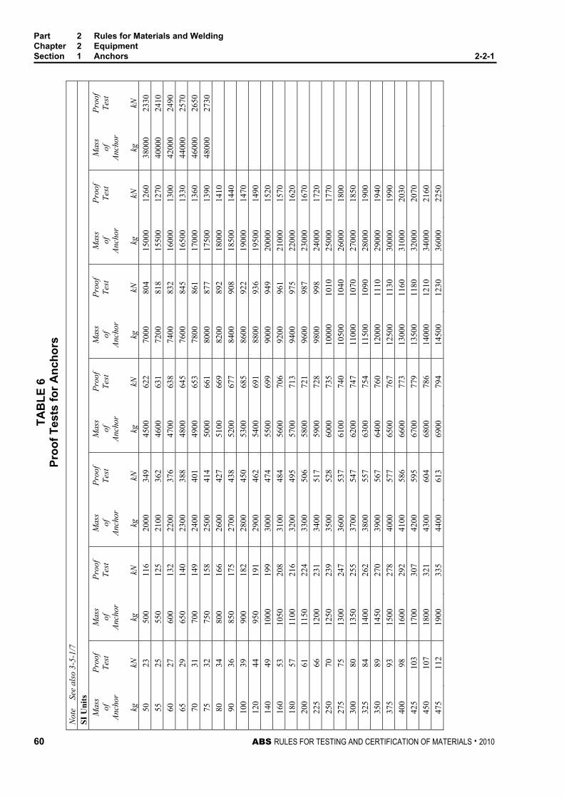
TAB
LE 6
Pr
oof T
ests
for A
ncho
rs
Not
e
See
also
3-5
-1/7
SI
Uni
ts
Mas
s of
An
chor
Proo
f Te
st
Mas
s of
An
chor
Proo
f Te
st
Mas
s of
An
chor
Proo
f Te
st
Mas
s of
An
chor
Proo
f Te
st
Mas
s of
An
chor
Proo
f Te
st
Mas
s of
An
chor
Proo
f Te
st
Mas
s of
An
chor
Proo
f Te
st
kg
kN
kg
kN
kg
kN
kg
kN
kg
kN
kg
kN
kg
kN
50
23
500
116
2000
34
9 45
00
622
7000
80
4 15
000
1260
38
000
2330
55
25
55
0 12
5 21
00
362
4600
63
1 72
00
818
1550
0 12
70
4000
0 24
10
60
27
600
132
2200
37
6 47
00
638
7400
83
2 16
000
1300
42
000
2490
65
29
65
0 14
0 23
00
388
4800
64
5 76
00
845
1650
0 13
30
4400
0 25
70
70
31
700
149
2400
40
1 49
00
653
7800
86
1 17
000
1360
46
000
2650
75
32
75
0 15
8 25
00
414
5000
66
1 80
00
877
1750
0 13
90
4800
0 27
30
80
34
800
166
2600
42
7 51
00
669
8200
89
2 18
000
1410
90
36
85
0 17
5 27
00
438
5200
67
7 84
00
908
1850
0 14
40
100
39
900
182
2800
45
0 53
00
685
8600
92
2 19
000
1470
12
0 44
95
0 19
1 29
00
462
5400
69
1 88
00
936
1950
0 14
90
140
49
1000
19
9 30
00
474
5500
69
9 90
00
949
2000
0 15
20
160
53
1050
20
8 31
00
484
5600
70
6 92
00
961
2100
0 15
70
180
57
1100
21
6 32
00
495
5700
71
3 94
00
975
2200
0 16
20
200
61
1150
22
4 33
00
506
5800
72
1 96
00
987
2300
0 16
70
225
66
1200
23
1 34
00
517
5900
72
8 98
00
998
2400
0 17
20
250
70
1250
23
9 35
00
528
6000
73
5 10
000
1010
25
000
1770
27
5 75
13
00
247
3600
53
7 61
00
740
1050
0 10
40
2600
0 18
00
300
80
1350
25
5 37
00
547
6200
74
7 11
000
1070
27
000
1850
32
5 84
14
00
262
3800
55
7 63
00
754
1150
0 10
90
2800
0 19
00
350
89
1450
27
0 39
00
567
6400
76
0 12
000
1110
29
000
1940
37
5 93
15
00
278
4000
57
7 65
00
767
1250
0 11
30
3000
0 19
90
400
98
1600
29
2 41
00
586
6600
77
3 13
000
1160
31
000
2030
42
5 10
3 17
00
307
4200
59
5 67
00
779
1350
0 11
80
3200
0 20
70
450
107
1800
32
1 43
00
604
6800
78
6 14
000
1210
34
000
2160
47
5 11
2 19
00
335
4400
61
3 69
00
794
1450
0 12
30
3600
0 22
50
Part 2 Rules for Materials and Welding Chapter 2 Equipment Section 1 Anchors 2-2-1
60 ABS RULES FOR TESTING AND CERTIFICATION OF MATERIALS . 2010

TAB
LE 6
(con
tinue
d)
Proo
f Tes
ts fo
r Anc
hors
N
ote
Se
e al
so 3
-5-1
/7
Met
ric
Uni
ts
Mas
s of
An
chor
Proo
f Te
st
Mas
s of
An
chor
Proo
f Te
st
Mas
s of
An
chor
Proo
f Te
st
Mas
s of
An
chor
Proo
f Te
st
Mas
s of
An
chor
Proo
f Te
st
Mas
s of
An
chor
Proo
f Te
st
Mas
s of
An
chor
Proo
f Te
st
kg
kgf
kg
kgf
kg
kgf
kg
kgf
kg
kgf
kg
kgf
kg
kgf
50
2370
50
0 11
800
2000
35
600
4500
63
400
7000
82
000
1500
0 12
8000
38
000
2380
00
55
2570
55
0 12
700
2100
36
900
4600
64
300
7200
83
400
1550
0 13
0000
40
000
2460
00
60
2760
60
0 13
500
2200
38
300
4700
65
100
7400
84
800
1600
0 13
3000
42
000
2540
00
65
2950
65
0 14
300
2300
39
600
4800
65
800
7600
86
200
1650
0 13
6000
44
000
2620
00
70
3130
70
0 15
200
2400
40
900
4900
66
600
7800
87
800
1700
0 13
9000
46
000
2700
00
75
3300
75
0 16
100
2500
42
200
5000
67
400
8000
89
400
1750
0 14
2000
48
000
2780
00
80
3460
80
0 16
900
2600
43
500
5100
68
200
8200
91
000
1800
0 14
4000
90
37
00
850
1780
0 27
00
4470
0 52
00
6900
0 84
00
9260
0 18
500
1470
00
100
3990
90
0 18
600
2800
45
900
5300
69
800
8600
94
000
1900
0 15
0000
12
0 45
20
950
1950
0 29
00
4710
0 54
00
7050
0 88
00
9540
0 19
500
1520
00
140
5000
10
00
2030
0 30
00
4830
0 55
00
7130
0 90
00
9680
0 20
000
1550
00
160
5430
10
50
2120
0 31
00
4940
0 56
00
7200
0 92
00
9800
0 21
000
1600
00
180
5850
11
00
2200
0 32
00
5050
0 57
00
7270
0 94
00
9940
0 22
000
1650
00
200
6250
11
50
2280
0 33
00
5160
0 58
00
7350
0 96
00
1006
00
2300
0 17
0000
22
5 67
10
1200
23
600
3400
52
700
5900
74
200
9800
10
1800
24
000
1750
00
250
7180
12
50
2440
0 35
00
5380
0 60
00
7490
0 10
000
1030
00
2500
0 18
0000
27
5 76
40
1300
25
200
3600
54
800
6100
75
500
1050
0 10
6000
26
000
1840
00
300
8110
13
50
2600
0 37
00
5580
0 62
00
7620
0 11
000
1090
00
2700
0 18
9000
32
5 85
80
1400
26
700
3800
56
800
6300
76
900
1150
0 11
1000
28
000
1940
00
350
9050
14
50
2750
0 39
00
5780
0 64
00
7750
0 12
000
1130
00
2900
0 19
8000
37
5 95
20
1500
28
300
4000
58
800
6500
78
200
1250
0 11
5000
30
000
2030
00
400
9980
16
00
2980
0 41
00
5980
0 66
00
7880
0 13
000
1180
00
3100
0 20
7000
42
5 10
500
1700
31
300
4200
60
700
6700
79
400
1350
0 12
0000
32
000
2110
00
450
1090
0 18
00
3270
0 43
00
6160
0 68
00
8020
0 14
000
1230
00
3400
0 22
0000
47
5 11
400
1900
34
200
4400
62
500
6900
81
000
1450
0 12
5000
36
000
2290
00
Part 2 Rules for Materials and Welding Chapter 2 Equipment Section 1 Anchors 2-2-1
ABS RULES FOR TESTING AND CERTIFICATION OF MATERIALS . 2010 61

TAB
LE 6
(con
tinue
d)
Proo
f Tes
ts fo
r Anc
hors
N
ote
Se
e al
so 3
-5-1
/7
US
Uni
ts
Mas
s of
An
chor
Proo
f Te
st
Mas
s of
An
chor
Proo
f Te
st
Mas
s of
An
chor
Proo
f Te
st
Mas
s of
An
chor
Proo
f Te
st
Mas
s of
An
chor
Proo
f Te
st
Mas
s of
An
chor
Proo
f Te
st
Mas
s of
An
chor
Proo
f Te
st
Mas
s of
An
chor
Proo
f Te
st
lb
lbf
lb
lbf
lb
lbf
lb
lbf
lb
lbf
lb
lbf
lb
lbf
lb
lbf
100
5000
10
00
2410
0 30
00
5770
0 50
00
8650
0 70
00
1105
00
9000
13
1500
28
000
2560
00
5600
0 40
0000
12
5 59
00
1100
25
900
3100
59
200
5100
87
800
7100
11
2000
95
00
1360
00
2900
0 26
2000
58
000
4100
00
150
6800
12
00
2770
0 32
00
6070
0 52
00
8910
0 72
00
1130
00
1000
0 14
0500
30
000
2660
00
6000
0 41
9000
17
5 76
00
1300
29
500
3300
62
200
5300
90
400
7300
11
4000
11
000
1485
00
3100
0 27
2000
62
000
4280
00
200
8300
14
00
3120
0 34
00
6370
0 54
00
9170
0 74
00
1150
00
1200
0 15
6000
32
000
2750
00
6400
0 43
7000
25
0 97
00
1500
32
900
3500
65
200
5500
93
000
7500
11
6000
13
000
1635
00
3300
0 28
1000
66
000
4460
00
300
1090
0 16
00
3460
0 36
00
6670
0 56
00
9430
0 76
00
1170
00
1400
0 17
0500
34
000
2870
00
6800
0 45
5000
35
0 12
000
1700
36
300
3700
68
200
5700
95
500
7700
11
8000
15
000
1770
00
3500
0 29
2000
70
000
4640
00
400
1300
0 18
00
3800
0 38
00
6970
0 58
00
9670
0 78
00
1200
00
1600
0 18
5000
36
000
2980
00
7500
0 48
6000
45
0 14
000
1900
39
700
3900
71
200
5900
97
900
7900
12
0500
17
000
1920
00
3700
0 30
3000
80
000
5070
00
500
1500
0 20
00
4140
0 40
00
7260
0 60
00
9910
0 80
00
1215
00
1800
0 20
0000
38
000
3090
00
8500
0 52
8000
55
0 16
000
2100
43
100
4100
74
100
6100
10
0500
81
00
1225
00
1900
0 20
8000
39
000
3140
00
9000
0 54
9000
60
0 16
900
2200
44
700
4200
75
500
6200
10
1500
82
00
1235
00
2000
0 21
4000
40
000
3200
00
9500
0 56
9000
65
0 17
800
2300
46
400
4300
76
900
6300
10
2500
83
00
1245
00
2100
0 22
1000
42
000
3300
00
1000
00
5900
00
700
1870
0 24
00
4800
0 44
00
7830
0 64
00
1040
00
8400
12
5500
22
000
2270
00
4400
0 34
1000
10
5000
61
0000
75
0 19
600
2500
49
700
4500
79
700
6500
10
5000
85
00
1265
00
2300
0 23
2000
46
000
3510
00
1100
00
6300
00
800
2050
0 26
00
5130
0 46
00
8110
0 66
00
1065
00
8600
12
7500
24
000
2390
00
4800
0 36
1000
85
0 21
400
2700
52
900
4700
82
500
6700
10
7500
87
00
1285
00
2500
0 24
3000
50
000
3710
00
900
2230
0 28
00
5450
0 48
00
8380
0 68
00
1085
00
8800
12
9500
26
000
2470
00
5200
0 38
1000
95
0 23
200
2900
56
100
4900
85
200
6900
10
9500
89
00
1305
00
2700
0 25
1000
54
000
3900
00
Part 2 Rules for Materials and Welding Chapter 2 Equipment Section 1 Anchors 2-2-1
62 ABS RULES FOR TESTING AND CERTIFICATION OF MATERIALS . 2010

ABS RULES FOR TESTING AND CERTIFICATION OF MATERIALS . 2010 63
P A R T S e c t i o n 2 : A n c h o r C h a i n
2 C H A P T E R 2 Equipment
S E C T I O N 2 Anchor Chain
1 Scope Three grades of stud-link anchor chain are covered, and are described as follows:
Strength Level Grade Method of Manufacture Normal Strength 1 Flash Butt-welded
High Strength 2a 2b
Flash Butt-welded or Drop-forged Cast Steel
Extra-high Strength 3a 3b
Flash Butt-welded or Drop-forged Cast Steel
3 General All chain is to have a workmanlike finish and be free from injurious defects. There is to be an odd number of links in each shot of anchor chain cable to insure shackles leading over the windlass are in the same position.
5 Specially Approved Chain Steel chain made by processes or to requirements differing from those shown in 2-2-2/Table 1 and certain types of drop-forged chain will be subject to special consideration.
7 Qualification of Manufacturers
7.1 General (2005) Manufacturers of Grades 2 and 3 chain and chain accessories are to be approved by the Bureau and are to submit their manufacturing process and material specifications for review. Data in support of mechanical properties, weld soundness (when applicable) and compliance with the Rules in all respects are also to be submitted for review and approval.
7.3 Locking Pins in Accessories Locking pins in detachable connecting links are to have taper contact at both top and bottom in the link halves. Lead or other acceptable material is to be used for plugging the locking pin hole which is to contain an appropriate undercut recess or equivalent arrangement to secure the plug.

Part 2 Rules for Materials and Welding Chapter 2 Equipment Section 2 Anchor Chain 2-2-2
64 ABS RULES FOR TESTING AND CERTIFICATION OF MATERIALS . 2010
7.5 Stud Attachment (2005) Studs are to be securely fastened by press fitting or welding with an approved procedure. When the stud is welded in place, the weld is to be opposite the flash butt weld in the chain. The welding is to be carried out in the horizontal position at least on both faces of the link for a length sufficient to hold the stud securely in place. Any welding of chain subsequent to the approved manufacturing process is to be approved by the attending Surveyor.
Welding of studs is to be in accordance with an approved procedure subject to the following conditions:
i) The studs must be of weldable steel.
ii) The studs are to be welded at one end only, i.e., opposite to the weldment of the link. The stud ends must fit the inside of the link without appreciable gap.
iii) The welds, preferably in the horizontal position, shall be executed by qualified welders using suitable welding consumables.
iv) All welds must be carried out before the final heat treatment of the chain cable.
v) The welds must be free from defects liable to impair the proper use of the chain. Under-cuts, end craters and similar defects are to be ground off, where necessary.
The Bureau reserves the right to call for a procedure test for the welding of chain studs.
9 Chain Dimensions and Tolerances
9.1 Shape Each link is to be uniform and symmetrical, and is to have smooth internal radii that are to be at least 0.65 times the chain diameter.
9.3 Dimensions (2005) The dimensions, shape and proportions of links and accessories must conform to an approved recognized standard, such as ISO 1704, or the designs are to be specially approved
After proof testing, measurements are to be taken on at least one link per each 27.5 m (15 fathoms) of chain tested and are to conform to the dimensions shown below.
Common Link
Crown
0.65d
3d
6d
3.6d
d = diameter of the link
d

Part 2 Rules for Materials and Welding Chapter 2 Equipment Section 2 Anchor Chain 2-2-2
ABS RULES FOR TESTING AND CERTIFICATION OF MATERIALS . 2010 65
9.5 Tolerances (1999) The minus tolerances on the diameter in the plane of the link at the crown are permitted to the extent shown below, provided the cross-sectional area of the link at that point is at least the theoretical area of the nominal diameter:
Chain Diameter in mm (in.) Crown Minus Tolerance Over Up to in mm (in.) — 40 (19/16) 1 (1/32)
40 (19/16) 84 (35/16) 2 (1/16)
84 (35/16) 122 (43/4) 3 (1/8)
122 (43/4) 162 (63/8) 4 (5/32)
No minus tolerance on the diameter is allowed at locations other than the crown.
The plus tolerance on the diameter is not to exceed 5% of the nominal diameter. The manufacturer’s specification for plus tolerance in way of weld is to be submitted for approval.
Subject to 2-2-2/9.7, the tolerances on other dimensions in 2-2-2/9.3 are not to exceed ±2.5%.
Studs are to be located in the links centrally and at right angles to the sides of the link, except that the studs for the final link at each end of any length may be located off-center to facilitate the insertion of the joining shackle. The following tolerances are acceptable, provided that the stud fits snugly and its ends lie practically flush against the inside of the link.
Maximum off-center distance “X”: 10% of the nominal diameter, d
Maximum deviation angle “α” from the 90° position: 4°
The tolerances are to be measured, as follows:
Final Link
a
A
α
d
X = A - a2
Off-center distance

Part 2 Rules for Materials and Welding Chapter 2 Equipment Section 2 Anchor Chain 2-2-2
66 ABS RULES FOR TESTING AND CERTIFICATION OF MATERIALS . 2010
9.7 Length Over Five Links After completion of the proof testing, the length over five links is to be measured while applying a tension of approximately 10% of the applied proof load. The Surveyor is to verify the length over a five link measurement from at least three locations per each 27.5 m (15 fathoms) of chain tested. The allowable tolerance for the length over any five common links is 0.0% of the chain diameter below, and 55% of the chain diameter above the length given in 2-2-2/Table 2.
11 Material for Chain
11.1 General 11.1.1 Process of Steel Manufacture and Deoxidation (1996)
The steel used for the manufacture of chain is to be made by the open-hearth, basic-oxygen, electric-furnace or such other process as may be specially approved.
Rimmed steel is not acceptable for any grade of chain.
11.1.2 Chemical Composition (1996) The chemical composition of the material for chain manufacture is to be determined by the steelmaker on samples taken from each ladle of each heat and is to comply with the approved specification of the chain manufacturer.
13 Material Testing
13.1 Heat Treatment of Test Specimens Test specimens are to be taken from material heat-treated in the same manner as intended for the finished chain, except that in the case of Grades 1 and 2a flash butt-welded chain, test specimens may be taken from material in either the as-rolled or heat-treated condition.
13.3 Number of Tests One set of tests consisting of one tension, and one bend or three impact test specimens, as required in 2-2-2/Table 1, are to be taken from the largest casting or drop forging from each lot of 50 tons or fraction thereof from each heat.
13.5 Tension Test Specimens (1996) For cast or drop-forged links, machined type specimens are to be used. They are to be cut and notched as shown in 2-2-2/Figure 1. The tension-test results for stud-link anchor chain materials are to meet the applicable requirements shown in 2-2-2/Table 1.
The required minimum percentage elongation values in 2-2-2/Table 1 are based on specimens having gauge lengths equal to 5 times the diameter. For specimens having other gauge lengths, the equivalent elongation value is to be calculated by the following equation:
n = 2E( A /L)0.4
where
n = equivalent minimum elongation
A = actual cross-sectional area of the specimen
L = actual gauge length
E = specified minimum percentage elongation for specimens having a gauge length of 5 times the diameter
The above equation is not applicable to quenched and tempered steel, for which the specimen is to have a gauge length of 5 times the specimen diameters.
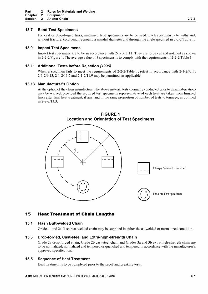
Part 2 Rules for Materials and Welding Chapter 2 Equipment Section 2 Anchor Chain 2-2-2
ABS RULES FOR TESTING AND CERTIFICATION OF MATERIALS . 2010 67
13.7 Bend Test Specimens For cast or drop-forged links, machined type specimens are to be used. Each specimen is to withstand, without fracture, cold bending around a mandril diameter and through the angle specified in 2-2-2/Table 1.
13.9 Impact Test Specimens Impact test specimens are to be in accordance with 2-1-1/11.11. They are to be cut and notched as shown in 2-2-2/Figure 1. The average value of 3 specimens is to comply with the requirements of 2-2-2/Table 1.
13.11 Additional Tests before Rejection (1996) When a specimen fails to meet the requirements of 2-2-2/Table 1, retest in accordance with 2-1-2/9.11, 2-1-2/9.13, 2-1-2/11.7 and 2-1-2/11.9 may be permitted, as applicable.
13.13 Manufacturer’s Option At the option of the chain manufacturer, the above material tests (normally conducted prior to chain fabrication) may be waived, provided the required test specimens representative of each heat are taken from finished links after final heat treatment, if any, and in the same proportion of number of tests to tonnage, as outlined in 2-2-2/13.3.
FIGURE 1 Location and Orientation of Test Specimens
2/3 r r
Charpy V-notch specimen
Tension Test specimen
15 Heat Treatment of Chain Lengths
15.1 Flash Butt-welded Chain Grades 1 and 2a flash butt-welded chain may be supplied in either the as-welded or normalized condition.
15.3 Drop-forged, Cast-steel and Extra-high-strength Chain Grade 2a drop-forged chain, Grade 2b cast-steel chain and Grades 3a and 3b extra-high-strength chain are to be normalized, normalized and tempered or quenched and tempered in accordance with the manufacturer’s approved specification.
15.5 Sequence of Heat Treatment Heat treatment is to be completed prior to the proof and breaking tests.

Part 2 Rules for Materials and Welding Chapter 2 Equipment Section 2 Anchor Chain 2-2-2
68 ABS RULES FOR TESTING AND CERTIFICATION OF MATERIALS . 2010
17 Testing and Inspection of Chain Lengths
17.1 General (1996) All anchor chain is to be subjected to breaking and proof tests in the presence of a Surveyor. The Surveyor is to satisfy himself that the testing machines are maintained in a satisfactory and accurate condition and is to keep a record of the dates and by whom the machines were rechecked or calibrated. Prior to test and inspection, the chain is to be free from paint or other coating which would tend to conceal defects. After proof testing, links are to be carefully examined for workmanship, concentricity, distortion, stud attachment, test grip damage, surface appearance and alignment of butt welds.
Provided their depth is not greater than 5% of the link diameter, surface discontinuities may be removed by grinding and blending to a smooth contour. The cross sectional area in way of the grinding is to be not less than the theoretical area of nominal chain diameter. Links repaired by grinding are to be subjected to magnetic particle or dye penetrant inspection.
17.3 Chain Identification Each shot is to be stamped with a distinctive mark in order to identify it through the several processes of gauging, testing, measuring, examining, repairing and weighing, and in the event of the Surveyor being in attendance at the works while forged chains are being fabricated, which will ultimately be submitted for testing, the break test specimens will be selected as far as possible during the process of fabrication.
17.5 Testing Precautions Care is to be taken that arrangements are made for each link to be tested at least once. The gripping arrangements are to be such that they do not put any stress on the end links of the portion under test, except such stress as is equally applied to every link tested.
17.7 Weighing of Tested Chain When chains have satisfactorily passed the requirements, they are to be weighed, together with the shackles forming the outfit, and this actual weight will be given on the certificate of test.
17.9 Testing of Used Chain When a chain, which has been in use, is submitted for testing or retesting, the size for testing purposes is to be the original chain diameter. The certificate issued for such chain will include for descriptive purposes the original chain diameter as well as the mean diameter of the part most worn, and will be marked, “This chain is not new, and has been previously used’’.
19 Details of Tests on Chain Lengths
19.1 Breaking Test (2005) A break-test specimen consisting of at least three links is to be taken from the chain or produced at the same time and the same way as the chain. Where produced separately, the specimen is to be securely attached to the chain during any heat treatment. One specimen is to be taken from each four 27.5 m (15 fathoms) lengths or less of flash butt-welded or drop-forged chain and one from each heat treatment batch with a minimum of one from each four 27.5 m (15 fathoms) lengths or less of cast-steel chain. Each specimen is to be subjected to the applicable breaking load given in 2-2-2/Table 2 (stud-link chain). The breaking load test is to be carried out in the presence of the Surveyor and is to be maintained for a minimum of 30 seconds. A specimen will be considered to have successfully passed the test if there is no sign of fracture after application of the required load. Special attention is to be given to the visual inspection of the flash butt weld. Where the first test is not satisfactory, one more specimen may be cut out and subjected to the breaking load. If this test fails, the shot is to be rejected, and additional specimens are to be cut from each of the three remaining shots of 27.5 m (15 fathoms) or less and subjected to the breaking load. In such cases, each shot from which the satisfactory break specimens have been taken is to be rejoined and may be accepted, provided it passes the required proof test. All breaking test specimens are to be subsequently discarded.

Part 2 Rules for Materials and Welding Chapter 2 Equipment Section 2 Anchor Chain 2-2-2
ABS RULES FOR TESTING AND CERTIFICATION OF MATERIALS . 2010 69
Alternative test procedures to the required breaking test of chain of Grades 2a, 2b, 3a, and 3b may be accepted. This alternative procedure consists of additional mechanical tests and the preparation of macro sections on a two or three link sample of chain taken from every four lengths of 27.5 m (15 fathoms) or less of completed chain. In the case of Grade 3a or 3b chain, the two or three link sample is not to be taken from the same length of chain as that length from which the link to be mechanically tested, according to 2-2-2/19.5, is taken.
19.3 Proof Test Each shot of chain of 27.5 m (15 fathoms) length or less and the entire length of chain when produced in lengths longer than 27.5 m (15 fathoms) is to withstand the applicable proof load indicated in 2-2-2/Table 2 (stud-link chain). Upon special request and when approved by the Bureau, detachable links may be subjected to a greater proof load than required for the chain. After the proof test, the length of chain is to be ascertained and the chain carefully examined. Any link showing surface defects or excessive deformation is to be taken out and the chain repaired, after which the proof test is again to be applied and the chain re-examined. If one link breaks under the proof test, a joining link is to be inserted and the proof test again applied; if a second link breaks, the shot or length under test is to be rejected. For chain produced in long continuous lengths, if more than one link breaks under proof test, the entire length is to be rejected unless approved otherwise.
19.5 Mechanical Tests on Completed Chain (2005) One link from every four lengths of 27.5 m (15 fathoms) or less of
Grade 2a flash butt welded chain delivered in as welded condition, and
Grades 3a or 3b chain
is to be subjected to a set of mechanical tests consisting of one tension and three impact tests. The mechanical tests are to be carried out in the presence of the Surveyor.
In the case of a welded chain, the above mentioned test specimens are to be taken from the base metal of the link opposite to the weldment and, additionally, three impact specimens are to be taken with notches at the weld center. The results of the tests are to comply with the requirements given in 2-2-2/Table 1. When the results of the original tests fail to meet the requirements, retests in accordance with 2-1-2/9.11 and 2-1-2/11.7 may be permitted, as applicable.
19.7 Mechanical and Breaking Tests on Chain Produced in Long Continuous Lengths When chain is produced in lengths longer than 27.5 m (15 fathoms), the test frequency for the mechanical and breaking tests required in 2-2-2/19.1 and 2-2-2/19.5 are to be based on tests at regular intervals according to the following table:
Nominal Chain Size
Maximum Specified Length to Obtain Samples
mm in. m ft Min to 48 Min to 17/8 91 300 50 to 60 2 to 23/8 110 360 64 to 73 21/2 to 27/8 131 430 76 to 85 3 to 33/8 152 500 87 to 98 31/2 to 37/8 175 575
102 to 111 4 to 43/8 198 650
If an order or a fraction of an order is less than the specified length, that length is to be subject to all tests required for a full length.

Part 2 Rules for Materials and Welding Chapter 2 Equipment Section 2 Anchor Chain 2-2-2
70 ABS RULES FOR TESTING AND CERTIFICATION OF MATERIALS . 2010
21 Marking for Chain (2001) The shackles and the end links of each length and one link in every 27.5 m (15 fathoms) of stud-link chain, made in a continuous length without joining shackles, are to be clearly stamped by the manufacturer as shown in 2-2-2/Figure 2 in location A, B and C. When Kenter shackles are used, the marking is to be clearly stamped on the Kenter shackle and on both adjoining common links. Any accessory tested to a break load for a lower grade chain, as permitted in 2-2-2/23.13, is to be marked with the grade of the chain to which it is tested.
FIGURE 2 Marking for Chain
A B A B
C C
A B
C
A The Number of the Certificate (Furnished by the Surveyor) 78 PT1234 B Signifying that the Chain has been satisfactorily tested to the Bureau
Requirements and the Grade as Applicable AB/1, AB/2 or AB/3
C Nominal Chain Diameter in mm or in. (When chain manufacturers emboss the chain diameter in a permanent manner by some suitable means such as forging or casting, marking of the chain diameter in location C may be omitted.)
23 Anchor Chain Accessories
23.1 Dimensions and Dimensional Tolerances (1996) The dimensions of anchor chain accessories are to be in accordance with a recognized standard such as ISO 1704. The following tolerances are applicable to anchor chain accessories.
Nominal diameter: +5%, -0%
Other dimensions: ±2.5%
23.3 Material Testing Test specimens are to be taken either from finished accessories or from special test bars indicated in 2-2-2/23.5 and 2-2-2/23.7. In all cases, the specimens are to be taken from pieces representing the largest diameter accessory in the lot. A lot is defined as the accessories of the same grade, made from the same heat of steel and heat-treated in the same furnace charge where the diameter does not differ by more than 25 mm (1 in.). Test results are to comply with 2-2-2/Table 1 or such other specification as may be specially approved. When the results of original tests fail to meet the requirements, retests in accordance with 2-1-2/9.11 and 2-1-2/11.7 may be permitted, as applicable.
Part 2 Rules for Materials and Welding Chapter 2 Equipment Section 2 Anchor Chain 2-2-2
ABS RULES FOR TESTING AND CERTIFICATION OF MATERIALS . 2010 71
23.5 Cast Accessories Test specimens may be taken from integrally or separately cast test blocks, heat-treated together with the accessories represented.
23.7 Forged Accessories Test specimens may be taken from a special forging, representative of the accessories in the lot. In such cases, the special forging is to be subjected to approximately the same amount of working and reduction as the forging represented, and is to be heat-treated with the forgings represented.
23.9 Inspection All accessories are to be inspected by magnetic particle or other suitable method to assure freedom from injurious surface defects. Special attention is to be given to welds.
23.11 Hardness Test All accessories are to be subjected to a Brinell hardness test to meet the following:
Grade
Brinell Hardness Number Minimum 10 mm ball, 3000 kg load
1 120 2 145 3 207
23.13 Break Test (2001) Break tests are to be made on 1 out of 25 accessories (or 1 out of 50 in the case of Kenter shackles), representative of the same type, grade and heat treatment procedure, but not necessarily representative of each heat of steel, heat treatment charge or individual purchase order. When the range of Brinell hardness readings of these accessories in the batch exceed 30 Brinell hardness numbers, the accessories represented by the lowest and highest Brinell hardness readings are to be tested. This requirement may be waived when the range of properties represented by the Brinell hardness numbers is established to the satisfaction of the Surveyor. For accessories from the same lot (see 2-2-2/23.3), the Surveyor may reduce the number of break tests to a minimum of two per lot. All parts of the accessory subjected to a break test required by this subparagraph are to be subsequently discarded, except where further use is permitted by 2-2-2/23.13.1 below.
23.13.1 Use of Break Tested Parts (2001) Where it is demonstrated by either one of the following methods that the accessories can withstand at least 140% of the breaking test load prescribed in 2-2-2/Table 2 for the chain in which they are intended, such accessories may be used in service provided:
23.13.1(a) the material of the accessories is of higher grade than the chain (e.g., grade 3 accessories of grade 2 size in grade 2 chain), or
23.13.1(b) where an accessory of increased dimension is specially approved for the particular application and a procedure test is completed at 140% of the 2-2-2/Table 2 break test load. All parts of the accessories used in this procedure test are to be subsequently discarded.
In either case, each accessory requiring a break test is to be tested to 100% of the 2-2-2/Table 2 break load for the chain in which it is intended to be used.
23.15 Proof Tests Each accessory is to be subjected to a proof test in accordance with 2-2-2/19.3.

Part 2 Rules for Materials and Welding Chapter 2 Equipment Section 2 Anchor Chain 2-2-2
72 ABS RULES FOR TESTING AND CERTIFICATION OF MATERIALS . 2010
23.17 Markings The certificate number, AB/Chain Grade, and nominal chain diameter are to be steel die stamped on each accessory. The stamping of the nominal chain diameter may be omitted, provided the nominal chain diameter is cast or forged into the accessory. Markings are to be located in such a manner as to be readily visible when completely assembled together with the chain.
25 Unstudded Short-link Chain
25.1 General Unstudded short-link chain is to meet the requirements specified in 2-2-2/3 and 2-2-2/11. Material is to be in accordance with the manufacturer’s specification which is to be the equivalent of normal strength Grade 1 requirements of 2-2-2/Table 1.
25.3 Testing Breaking and proof testing are to be in accordance with 2-2-2/19 and subjected to the applicable testing loads as given in 2-2-2/Table 3.
25.5 Marking One link, including the end link in every 4.5 m (2.5 fathoms), is to be steel die stamped by the manufacturer as prescribed in locations A, B and C as shown in 2-2-2/Figure 1. In special cases, shots of comparatively small size may be marked or stenciled in lieu of die stamping or the markings may be shown on a metal tag attached at every 4.5 m (2.5 fathoms).
TABLE 1 Chain Materials – Mechanical Properties (1999)
Chain Grade Grade 1 Grade 2 Grade 3 Yield Point
N/mm2 (kgf/mm2, ksi) - 295
(30, 42.8) 410
(42, 60) Tensile Range
N/mm2 (kgf/mm2, ksi) 370-490
(38-51, 53.7-71.1) 490-690
(50-70, 71.1-99.6) 690 min.
(70, 99.6) min. Elongation (5D), min % 25 22 17
Reduction of Area, min % - - 40 Average Impact Value @ 0°C (32°F), J (kgf-m, ft-lbf)
base metal - 27 (1) (2.8, 20) 60 (6, 43) at weld center - 27 (1) (2.8, 20) 50 (5, 36)
Bend Test mandrel dia.(2) 2T 3T Angle (degree) 180 180
Notes: 1 Impact test for Grade 2 chain material is required for flash butt welded chain to be
delivered in as-welded condition.
2 T = diameter or thickness of test specimen.

TAB
LE 2
St
ud-li
nk A
ncho
r-ch
ain
Proo
f and
Bre
ak T
ests
SI
Uni
ts
Nor
mal
Str
engt
h
G
rade
1
H
igh
Stre
ngth
Gra
de 2
Extr
a-hi
gh S
tren
gth
Gra
de 3
N
orm
al S
tren
gth
Gra
de 1
Hig
h St
reng
th
G
rade
2
Ex
tra-
high
Str
engt
h
Gra
de 3
Cha
in
Dia
met
er
Leng
th o
f Fi
ve
Link
s
Proo
f Lo
ad
Brea
king
Lo
ad
Proo
f Lo
ad
Brea
king
Lo
ad
Proo
f Lo
ad
Brea
king
Lo
ad
Mas
s ki
logr
ams
per 2
7.5
met
ers
Cha
in
Dia
met
er
Leng
th o
f Fi
ve
Link
s
Proo
f Lo
ad
Brea
king
Lo
ad
Proo
f Lo
ad
Brea
king
Lo
ad
Proo
f Lo
ad
Brea
king
Lo
ad
Mas
s ki
logr
ams
per 2
7.5
met
ers
mm
m
m
kN
kN
kN
kN
kN
kN
kg
mm
m
m
kN
kN
kN
kN
kN
kN
kg
12.5
27
5 46
.1
65.7
65
.7
92.2
92
.2
132.
4 11
0
70
15
40
1294
.5
1843
.7
1843
.7
2579
.1
2579
.1
3687
.3
2910
14
30
8 57
.9
82.4
82
.4
115.
7 11
5.7
164.
8 13
0
73
16
06
1392
.5
1990
.7
1990
.7
2794
.9
2794
.9
3991
.3
3180
16
35
2 75
.5
106.
9 10
6.9
150.
0 15
0.0
215.
7 17
0
76
16
72
1500
.4
2147
.6
2147
.6
3010
.6
3010
.6
4295
.3
3470
17
.5
385
89.3
12
7.5
127.
5 17
9.5
179.
5 26
0.8
180
78
1716
15
78.9
22
55.5
22
55.5
31
57.7
31
57.7
45
01.3
36
50
19
418
104.
9 15
0.0
150.
9 21
0.8
210.
8 30
1.1
220
81
1782
16
86.7
24
12.4
24
12.4
33
83.3
33
83.3
48
24.9
39
30
20.5
45
1 12
2.6
174.
6 17
4.6
244.
2 24
4.2
349.
1 26
0
84
18
48
1804
.4
2579
.1
2579
.1
3608
.8
3608
.8
5158
.3
4250
22
48
4 14
0.2
200.
1 20
0.1
280.
5 28
0.5
401.
1 30
0
87
19
14
1922
.1
2745
.9
2745
.9
3854
.0
3854
.0
5501
.5
4560
24
52
8 16
6.7
237.
3 23
7.3
332.
4 33
2.4
475.
6 34
0
90
19
80
2049
.6
2922
.4
2922
.4
4089
.4
4089
.4
5844
.8
4860
26
57
2 19
4.2
277.
5 27
7.5
389.
3 38
9.3
556.
0 42
0
92
20
24
2128
.0
3040
.1
3040
.1
4256
.1
4256
.1
6080
.1
5100
28
61
6 22
4.6
320.
7 32
0.7
449.
1 44
9.1
642.
3 48
0
95
20
90
2255
.5
3226
.4
3226
.4
4511
.0
4511
.0
6443
.0
5400
30
66
0 25
6.9
367.
7 36
7.7
513.
9 51
3.9
734.
5 55
0
97
21
34
2343
.8
3344
.1
3344
.1
4677
.8
4677
.8
6688
.1
5670
32
70
4 29
1.3
416.
8 41
6.8
582.
5 58
2.5
832.
6 61
0
98
21
56
2383
.0
3402
.9
3402
.9
4766
.0
4766
.0
6815
.6
5750
34
74
8 32
7.5
467.
8 46
7.8
655.
1 65
5.1
936.
5 70
0
10
0 22
00
2471
.3
3530
.4
3530
.4
4942
.6
4942
.6
7060
.8
6010
36
79
2 36
5.8
522.
7 52
2.7
731.
6 73
1.6
1049
.3
790
102
2244
25
59.5
36
57.9
36
57.9
51
19.1
51
19.1
73
15.8
62
50
38
836
406.
0 58
0.6
580.
6 81
2.0
812.
0 11
57.2
88
0
10
5 23
10
2696
.8
3854
.0
3854
.0
5393
.7
5393
.7
7698
.2
6600
40
88
0 44
8.2
640.
4 64
0.4
896.
3 89
6.3
1284
.7
970
107
2354
27
85.1
39
81.5
39
81.5
55
70.2
55
70.2
79
63.0
68
20
42
924
492.
3 70
3.1
703.
1 98
0.7
980.
7 14
02.3
10
70
108
2376
28
34.1
40
40.3
40
40.3
56
58.4
56
58.4
80
90.4
69
50
44
968
538.
4 76
8.8
768.
8 10
78.7
10
78.7
15
39.6
11
70
111
2442
29
71.4
42
46.3
42
46.3
59
42.8
59
42.8
84
82.8
72
90
46
1012
58
5.5
836.
5 83
6.5
1167
.0
1167
.0
1676
.9
1270
11
4 25
08
3108
.7
4442
.4
4442
.4
6227
.2
6227
.2
8894
.6
7640
48
10
56
635.
5 90
8.1
908.
1 12
74.9
12
74.9
18
14.2
13
80
117
2574
32
55.8
46
48.4
46
48.4
65
11.6
65
11.6
92
96.7
79
80
50
1100
68
6.5
980.
7 98
0.7
1372
.9
1372
.9
1961
.3
1480
12
0 26
40
3492
.9
4854
.3
4854
.3
6805
.8
6805
.8
9718
.4
8310
52
11
44
739.
4 10
59.1
10
59.1
14
80.8
14
80.8
21
08.4
16
00
122
2684
35
01.0
50
01.4
50
01.4
70
01.9
70
01.9
99
93.0
86
20
54
1188
79
4.3
1137
.6
1137
.6
1588
.7
1588
.7
2265
.3
1720
12
4 27
28
3599
.0
5138
.7
5138
.7
7198
.1
7198
.1
1027
7.4
8920
56
12
32
851.
2 12
16.0
12
16.0
17
06.4
17
06.4
24
32.0
18
50
127
2794
37
46.1
53
54.4
53
54.4
74
92.3
74
92.3
10
708.
9 93
80
58
1276
90
9.1
1294
.5
1294
.5
1814
.2
1814
.2
2598
.8
1990
13
0 28
60
3903
.0
5570
.2
5570
.2
7796
.3
7796
.3
1114
0.4
9840
60
13
20
968.
9 13
82.7
13
82.7
19
41.7
19
41.7
27
65.5
21
20
132
2904
40
01.1
57
17.3
57
17.3
80
02.2
80
02.2
11
424.
7 10
140
62
1364
10
29.7
14
71.0
14
71.0
20
59.4
20
59.4
29
42.0
22
50
137
3014
42
56.1
60
80.1
60
80.1
85
12.2
85
12.2
12
160.
2 10
910
64
1408
10
98.3
15
59.3
15
59.3
21
86.9
21
86.9
31
28.3
24
40
142
3124
45
20.9
64
52.8
64
52.8
90
31.9
90
31.9
12
905.
6 11
670
66
1452
11
57.2
16
57.3
16
57.3
23
14.4
23
14.4
33
04.8
25
90
147
3234
47
85.6
68
35.2
68
35.2
95
61.5
95
61.5
13
660.
7 12
440
68
1496
12
25.8
17
45.6
17
45.6
24
51.7
24
51.7
35
01.0
27
50
152
3344
50
50.4
72
17.7
72
17.7
10
100.
8 10
100.
8 14
425.
6 13
200
157
3454
53
25.0
76
00.2
76
00.2
10
640.
2 10
640.
2 15
200.
3 14
000
Not
e:
The
wei
ght o
f cha
in is
not
to b
e m
ore
than
21 / 2
% u
nder
the
wei
ght s
peci
fied.
16
2 35
64
5599
.6
8002
.2
8002
.2
1119
9.2
1119
9.2
1599
4.6
1470
0
Part 2 Rules for Materials and Welding Chapter 2 Equipment Section 2 Anchor Chain 2-2-2
ABS RULES FOR TESTING AND CERTIFICATION OF MATERIALS . 2010 73

TAB
LE 2
(con
tinue
d)
Stud
-link
Anc
hor-
chai
n Pr
oof a
nd B
reak
Tes
ts
MK
S U
nits
Nor
mal
Str
engt
h
Gra
de 1
H
igh
Stre
ngth
G
rade
2
Extr
a-hi
gh S
tren
gth
Gra
de 3
Nor
mal
Str
engt
h
Gra
de 1
H
igh
Stre
ngth
G
rade
2
Extr
a-hi
gh S
tren
gth
Gra
de 3
Cha
in
Dia
met
er
Leng
th o
f Fi
ve
Link
s
Proo
f Lo
ad
Brea
king
Lo
ad
Proo
f Lo
ad
Brea
king
Lo
ad
Proo
f Lo
ad
Brea
king
Lo
ad
Mas
s ki
logr
ams
per 2
7.5
met
ers
Cha
in
Dia
met
er
Leng
th o
f Fi
ve
Link
s
Proo
f Lo
ad
Brea
king
Lo
ad
Proo
f Lo
ad
Brea
king
Lo
ad
Proo
f Lo
ad
Brea
king
Lo
ad
Mas
s ki
logr
ams
per 2
7.5
met
ers
mm
m
m
kgf
kgf
kgf
kgf
kgf
kgf
kg
mm
m
m
kgf
kgf
kgf
kgf
kgf
kgf
kg
12.5
27
5 47
00
6700
67
00
9400
94
00
1350
0 11
0
70
15
40
1320
00
1880
00
1880
00
2630
00
2630
00
3760
00
2910
14
30
8 59
00
8400
84
00
1180
0 11
800
1680
0 13
0
73
16
06
1420
00
2030
00
2030
00
2850
00
2850
00
4070
00
3180
16
35
2 77
00
1090
0 10
900
1530
0 15
300
2200
0 17
0
76
16
72
1530
00
2190
00
2190
00
3070
00
3070
00
4380
00
3470
17
.5
385
9100
13
000
1300
0 18
300
1830
0 26
100
180
78
1716
16
1000
23
0000
23
0000
32
2000
32
2000
45
9000
36
50
19
418
1070
0 15
300
1530
0 21
500
2150
0 30
700
220
81
1782
17
2000
24
6000
24
6000
34
5000
34
5000
49
2000
39
30
20.5
45
1 12
500
1780
0 17
800
2490
0 24
900
3560
0 26
0
84
18
48
1840
00
2630
00
2630
00
3680
00
3680
00
5260
00
4250
22
48
4 14
300
2040
0 20
400
2860
0 28
600
4090
0 30
0
87
19
14
1960
00
2800
00
2800
00
3930
00
3930
00
5610
00
4560
24
52
8 17
000
2420
0 24
200
3390
0 33
900
4850
0 34
0
90
19
80
2090
00
2980
00
2980
00
4170
00
4170
00
5960
00
4860
26
57
2 19
800
2830
0 28
300
3970
0 39
700
5670
0 42
0
92
20
24
2170
00
3100
00
3100
00
4340
00
4340
00
6200
00
5100
28
61
26
2290
0 32
700
3270
0 45
800
4580
0 65
500
480
95
2090
23
0000
32
9000
32
9000
46
0000
46
0000
65
7000
54
00
30
660
2620
0 37
500
3750
0 52
400
5240
0 74
900
550
97
2134
23
9000
34
1000
34
1000
47
7000
47
7000
68
2000
56
70
32
704
2970
0 42
500
4250
0 59
400
5940
0 84
900
610
98
2156
24
3000
34
7000
34
7000
48
6000
48
6000
69
5000
57
50
34
748
3340
0 47
700
4770
0 66
800
6680
0 95
500
700
100
2200
25
2000
36
0000
36
0000
50
4000
50
4000
72
0000
60
10
36
792
3730
0 53
300
5330
0 74
600
7460
0 10
7000
79
0
10
2 22
44
2610
00
3730
00
3730
00
5220
00
5220
00
7460
00
6250
38
83
6 41
400
5920
0 59
200
8280
0 82
800
1180
00
880
105
2310
27
5000
39
3000
39
3000
55
0000
55
0000
78
5000
66
00
40
880
4570
0 65
300
6530
0 91
400
9140
0 13
1000
97
0
10
7 23
54
2840
00
4060
00
4060
00
5680
00
5680
00
8120
00
6820
42
92
4 50
200
7170
0 71
700
1000
00
1000
00
1430
00
1070
10
8 23
76
2890
00
4120
00
4120
00
5770
00
5770
00
8250
00
6950
44
96
8 54
900
7840
0 78
400
1100
00
1100
00
1570
00
1170
11
1 24
42
3030
00
4330
00
4330
00
6060
00
6060
00
8650
00
7290
46
10
12
5970
0 85
300
8530
0 11
9000
11
9000
17
1000
12
70
114
2508
31
7000
45
3000
45
3000
63
5000
63
5000
90
7000
76
40
48
1056
64
800
9260
0 92
600
1300
00
1300
00
1850
00
1380
11
7 25
74
3320
00
4740
00
4740
00
6640
00
6640
00
9480
00
7980
50
11
00
7000
0 10
0000
10
0000
14
0000
14
0000
20
0000
14
80
120
2640
34
7000
49
5000
49
5000
69
4000
60
4000
99
1000
83
10
52
1144
75
400
1080
00
1080
00
1510
00
1510
00
2150
00
1600
12
2 26
84
3570
00
5100
00
5100
00
7140
00
7140
00
1019
000
8620
54
11
88
8100
0 11
6000
11
6000
16
2000
16
2000
23
1000
17
20
124
2728
36
7000
52
4000
52
4000
73
4000
73
4000
10
4800
0 89
20
56
1232
86
800
1240
00
1240
00
1740
00
1740
00
2480
00
1850
12
7 27
94
3820
00
5460
00
5460
00
7640
00
7640
00
1092
000
9380
58
12
76
9270
0 13
2000
13
2000
18
5000
18
5000
26
5000
19
90
130
2860
39
8000
56
8000
56
8000
79
5000
79
5000
11
3600
0 98
40
60
1320
98
800
1410
00
1410
00
1980
00
1980
00
2820
00
2120
13
2 29
04
4080
00
5830
00
5830
00
8160
00
8160
00
1165
000
1014
0 62
13
64
1050
00
1500
00
1500
00
2100
00
2100
00
3000
00
2250
13
7 30
14
4340
00
6200
00
6200
00
8680
00
8680
00
1240
000
1091
0 64
14
08
1120
00
1590
00
1590
00
2230
00
2230
00
3190
00
2440
14
2 31
24
4610
00
6580
00
6580
00
9210
00
9210
00
1316
000
1167
0 66
14
52
1180
00
1690
00
1690
00
2360
00
2360
00
3370
00
2590
14
7 32
34
4880
00
6970
00
6970
00
9750
00
9750
00
1393
000
1244
0 68
14
96
1250
00
1780
00
1780
00
2500
00
2500
00
3570
00
2750
15
2 33
44
5150
00
7360
00
7360
00
1030
000
1030
000
1471
000
1320
0
15
7 34
54
5430
00
7750
00
7750
00
1085
000
1085
000
1550
000
1400
0 N
ote:
Th
e w
eigh
t of c
hain
is n
ot to
be
mor
e th
an 2
1 / 2%
und
er th
e w
eigh
t spe
cifie
d.
162
3564
57
1000
81
6000
81
6000
11
4200
0 11
4200
0 16
3100
0 14
700
Part 2 Rules for Materials and Welding Chapter 2 Equipment Section 2 Anchor Chain 2-2-2
74 ABS RULES FOR TESTING AND CERTIFICATION OF MATERIALS . 2010

TAB
LE 2
(con
tinue
d)
Stud
-link
Anc
hor-
chai
n Pr
oof a
nd B
reak
Tes
ts
US
Uni
ts
N
orm
al S
tren
gth
G
rade
1
Hig
h St
reng
th
Gra
de 2
Ex
tra-
high
Str
engt
h G
rade
3
N
orm
al S
tren
gth
Gra
de 1
H
igh
Stre
ngth
G
rade
2
Extr
a-hi
gh S
tren
gth
Gra
de 3
Cha
in
Dia
m
eter
Leng
th o
f Fi
ve L
inks
Pr
oof
Load
Br
eaki
ng
Load
Pr
oof
Load
Br
eaki
ng
Load
Pr
oof
Load
Br
eaki
ng
Load
M
ass
poun
ds
per 1
5 fa
thom
s
Cha
in
Dia
m
eter
Leng
th o
f Fi
ve L
inks
Pr
oof
Load
Br
eaki
ng
Load
Pr
oof
Load
Br
eaki
ng
Load
Pr
oof
Load
Br
eaki
ng
Load
M
ass
poun
ds
per 1
5 fa
thom
s in
. ft
In
lbf
lbf
lbf
lbf
lbf
lbf
lb
in.
ft In
lb
f lb
f lb
f lb
f lb
f lb
f lb
1 / 2
-
11
1070
0 15
300
1530
0 21
400
2140
0 30
600
230
2 11
/ 16
4 11
1 /8
2770
00
3960
00
3960
00
5540
00
5540
00
7920
00
6110
9 / 1
6 1
0 3 / 8
13
500
1930
0 19
300
2700
0 27
000
3860
0 29
0
2
3 / 4
5 0
1 / 2
2890
00
4130
00
4130
00
5780
00
5780
00
8260
00
6410
5 / 8
1
1 3 / 4
16
600
2370
0 23
700
3320
0 33
200
4750
0 37
0
2
13/ 16
5
1 7 / 8
30
1000
43
1000
43
1000
60
3000
60
3000
86
1000
67
10
11/ 16
1
3 1 / 8
20
100
2860
0 28
600
4010
0 40
100
5730
0 41
0
2
7 / 8
5 3
1 / 4
3140
00
4490
00
4490
00
6280
00
6280
00
8970
00
7020
3 / 4
1
4 1 / 2
23
800
3400
0 34
000
4760
0 47
600
6800
0 48
0
2
15/ 16
5
4 5 / 8
32
7000
46
7000
46
7000
65
4000
65
4000
93
4000
73
30
13/ 16
1
5 7 / 8
27
800
3980
0 39
800
5570
0 55
700
7950
0 57
0
3
5 6
3400
00
4850
00
4850
00
6790
00
6790
00
9700
00
7650
7 / 8
1
7 1 / 4
32
200
4600
0 46
000
6440
0 64
400
9180
0 66
0
3
1 / 16
5 7
3 / 8
3530
00
5040
00
5040
00
7050
00
7050
00
1008
000
7980
15
/ 16
1 8
5 / 8
3680
0 52
600
5260
0 73
700
7370
0 10
5000
0 76
0
3
1 / 8
5 8
3 / 4
3660
00
5230
00
5230
00
7320
00
7320
00
1046
000
8320
1
1 10
41
800
5970
0 59
700
8630
0 83
600
1195
00
860
3 3 / 1
6 5
10 1 /
8 38
0000
54
2000
54
2000
75
9000
75
9000
10
8400
086
60
1 1 / 1
6 1
11 3 /
8 47
000
6720
0 67
200
9410
0 94
100
1350
00
970
3 1 / 4
5
11 1 /
2 39
3000
56
2000
56
2000
78
7000
78
7000
11
2400
090
10
1 1 / 8
2
0 3/
4 52
600
7500
0 75
000
1050
00
1050
00
1500
00
1080
3
5 / 16
6 0
7 / 8
4070
00
5820
00
5820
00
8140
00
8140
00
1163
000
9360
1
3 / 16
2 2
1 / 8
5840
0 83
400
8340
0 11
6500
11
6500
16
7000
12
20
3 3 / 8
6
2 1 / 4
42
1000
60
2000
60
2000
84
3000
84
3000
12
0400
097
30
1 1 / 4
2
3 1 / 2
64
500
9220
0 92
200
1290
00
1290
00
1840
00
1350
3
7 / 16
6 3
5 / 8
4350
00
6220
00
6220
00
8710
00
8710
00
1244
000
1010
0 1
5 / 16
2 4
7 / 8
7090
0 10
1500
10
1500
14
2000
14
2000
20
3000
14
90
3 1 / 2
6
5 45
0000
64
3000
64
3000
90
0000
90
0000
12
8500
010
500
1 3 / 8
2
6 1 / 4
77
500
1110
00
1110
00
1550
00
1550
00
2220
00
1630
3
9 / 16
6 6
3 / 8
4650
00
6640
00
6640
00
9290
00
9290
00
1327
000
1090
0 1
7 / 16
2 7
5 / 8
8450
0 12
0500
12
0500
16
9000
16
9000
24
1000
17
80
3 5 / 8
6
7 3 / 4
47
9000
68
5000
68
5000
95
8000
95
8000
13
6900
011
300
1 1 / 2
2
9 91
700
1310
00
1310
00
1835
00
1835
00
2620
00
1940
3
3 / 4
6 10
1 /2
5090
00
7280
00
7280
00
1019
000
1019
000
1455
000
1200
0 1
9 / 16
2 10
3 /8
9920
0 14
2000
14
2000
19
8500
19
8500
28
4000
20
90
3 7 / 8
7
1 1 / 4
54
0000
77
2000
77
2000
10
8000
010
8000
015
4300
012
900
1 5 / 8
2
11 3 /
4 10
8000
15
3000
15
3000
21
4000
21
4000
30
6000
22
40
3 15
/ 16
7 2
5 / 8
5560
00
7940
00
7940
00
1111
000
1111
000
1587
000
1330
0 1
11/ 16
3
1 1 / 8
11
5000
16
6500
16
6500
22
9000
22
9000
32
7000
24
10
4 7
4 57
1000
81
6000
81
6000
11
4300
011
4300
016
3200
013
700
1 3 / 4
3
2 1 / 2
12
3500
17
6000
17
6000
24
7000
24
7000
35
2000
25
90
4 1 / 8
7
6 3 / 4
60
3000
86
2000
86
2000
12
0700
012
0700
017
2400
014
600
1 13
/ 16
3 3
7 / 8
1320
00
1885
00
1885
00
2640
00
2640
00
3770
00
2790
4
1 / 4
7 9
1 / 2
6360
00
9080
00
9080
00
1272
000
1272
000
1817
000
1540
0 1
7 / 8
3 5
1 / 4
1405
00
2010
00
2010
00
2810
00
2810
00
4020
00
2980
4
3 / 8
8 0
1 / 4
6690
00
9560
00
9560
00
1338
000
1338
000
1911
000
1620
0 1
15/ 16
3
6 5 / 8
14
9500
21
4000
21
4000
29
9000
29
9000
42
7000
31
80
4 1 / 2
8
3 70
3000
10
0400
010
0400
014
0500
014
0500
020
0800
017
100
2 3
8 15
9000
22
7000
22
7000
31
8000
31
8000
45
4000
33
60
4 5 / 8
8
5 3 / 4
73
7000
10
5300
010
5300
014
7400
014
7400
021
0500
018
000
2 1 / 1
6 3
9 3 / 8
16
8500
24
1000
24
1000
33
7000
33
7000
48
2000
35
70
4 3 / 4
8
8 1 / 2
77
2000
11
0200
011
0200
015
4300
015
4300
022
0400
018
900
2 1 / 8
3
10 3 /
4 17
8500
25
5000
25
5000
35
7000
35
7000
51
0000
37
90
4 7 / 8
8
11 1 /
4 80
7000
11
5300
011
5300
016
1300
016
1300
023
0500
019
900
2 3 / 1
6 4
0 1 / 8
18
8500
26
9000
26
9000
37
7000
37
7000
53
8000
40
20
5 9
2 84
2000
12
0300
012
0300
016
8500
016
8500
024
0700
020
900
2 1 / 4
4
1 1 / 2
19
8500
28
4000
28
4000
39
6000
39
6000
57
0000
42
50
5 1 / 8
9
4 3 / 4
87
8000
12
5500
012
5500
017
5700
017
5700
025
0900
022
000
2 5 / 1
6 4
2 7 / 8
20
9000
29
9000
29
9000
41
8000
41
8000
59
8000
44
90
5 3 / 8
9
10 1 /
4 95
1000
13
5900
013
5900
019
0300
019
0300
027
1800
024
000
2 3 / 8
4
4 1 / 4
21
2000
31
4000
31
4000
44
0000
44
0000
62
8000
47
30
5 5 / 8
10
3
3 / 4
1026
000
1466
000
1466
000
2052
000
2052
000
2932
000
2610
0 2
7 / 16
4 5
5 / 8
2310
00
3300
00
3300
00
4620
00
4620
00
6600
00
4960
5
3 / 4
10
6 1 / 2
10
6400
015
2000
015
2000
021
2800
021
2800
030
3900
027
000
2 1 / 2
4
7 24
2000
34
6000
34
6000
48
4000
48
4000
69
2000
52
70
6 11
0
1140
000
1629
000
1629
000
2280
000
2280
000
3257
000
2910
0 2
9 / 16
4 8
3 / 8
2540
00
3630
00
3630
00
5070
00
5070
00
7260
00
5540
6
1 / 8
11
2 3 / 4
11
7900
016
8400
016
8400
023
5700
023
5700
033
6700
030
200
2 5 / 8
4
9 3 / 4
26
5000
37
9000
37
9000
53
0000
53
0000
75
8000
58
20
6 3 / 8
11
8
1 / 4
1256
000
1795
000
1795
000
2512
000
2512
000
3589
000
3240
0 N
ote:
Se
e al
so 2
-2-2
/9
Th
e w
eigh
t of c
hain
is n
ot to
be
mor
e th
an 2
1 / 2%
und
er th
e w
eigh
t spe
cifie
d.
Part 2 Rules for Materials and Welding Chapter 2 Equipment Section 2 Anchor Chain 2-2-2
ABS RULES FOR TESTING AND CERTIFICATION OF MATERIALS . 2010 75

Part 2 Rules for Materials and Welding Chapter 2 Equipment Section 2 Anchor Chain 2-2-2
76 ABS RULES FOR TESTING AND CERTIFICATION OF MATERIALS . 2010
TABLE 3 Unstudded Short-link Chain
SI Units (MKS Units) US Units Diameter of
Common Links
Breaking Test
Proof Test
Diameter of Common
Links
Breaking Test
Proof Test
mm kN kgf kN kgf
in. lbf lbf 6 11.6 1180 5.8 590 5/16 5040 2520 8 22.6 2300 11.3 1150 3/8 7280 3640 10 35.9 3660 17.9 1830 7/16 10080 5040 12 52.8 5380 26.4 2690 1/2 13440 6720 14 71.5 7290 35.8 3650 9/16 16800 8400
16 93.6 9540 46.8 4770 5/8 20720 10360 18 119.2 12150 59.9 6110 11/16 25200 12600 20 147.7 15060 74.4 7590 3/4 30240 15120 22 178.6 18210 89.7 9150 13/16 35392 17696 24 212.5 21670 106.5 10860 7/8 40880 20440
26 249.9 25480 125.0 12750 15/16 47040 23520 28 288.9 29460 144.5 14730 1 53760 26880 30 332.6 33920 166.8 16960 11/16 60480 30240 32 379.6 38710 189.5 19320 11/8 67760 33880 34 427.5 43590 213.6 21780 13/16 75712 37856
36 477.2 48660 239.3 24400 11/4 84000 42000 38 534.1 54460 267.1 27240 15/16 92400 46200 13/8 101360 50680 17/16 110880 55440 11/2 120960 60480

ABS RULES FOR TESTING AND CERTIFICATION OF MATERIALS . 2010 77
P A R T Section 3: Rolled Steel Bars for Chain, Cast and Forged Materials for Accessories and Materials for Studs
2 C H A P T E R 2 Equipment
S E C T I O N 3 Rolled Steel Bars for Chain, Cast and Forged Materials for Accessories and Materials for Studs
1 General (2005) Rolled steel bars Grades U1, U2 or U3 for Grade 1, 2 or 3 chains, cast and forged materials for accessories and materials for studs are to be in accordance with this section. Bars for offshore mooring chains are to be in accordance with the ABS Guide for the Certification of Offshore Mooring Chain. These Rules are not intended to replace or modify any part of a chain manufacturer’s specification approved by the Bureau.
1.1 Process of Manufacture (2005) The manufacturers of materials for anchor chain and accessories are to be approved. Approval is not required for Grade 1 bars. The bar manufacturers are to submit the manufacturing specifications and the details of the manufacturing procedure.
The steel is to be made by the open-hearth, basic oxygen, vacuum-arc remelt, electro-slag remelt electric-furnace or such other process as may be specially approved.
Unless otherwise stipulated, the steel bars are to be supplied in the as rolled condition.
1.3 Deoxidation Practice Bars are to be fully killed and, in addition, Grade U2 or U3 bars are to be produced to a fine grain practice.
1.5 Chemical Composition and Heat Treatment (1999) The chemical composition and heat treatment are to be in accordance with the manufacturer’s specification that is to be approved by the Bureau. In general, they are to conform to 2-2-3/Table 1.
1.7 Mechanical Properties (1999) Mechanical tests are to be carried out in accordance with 2-2-3/3 and the results are to meet the requirements in 2-2-2/Table 1.
1.9 Dimensional properties (1999) Unless otherwise approved, the tolerances on diameter and roundness (dmax − dmin) are to be within the limits listed in 2-2-3/Table 2, where dmax and dmin are the maximum and minimum diameter measured at the section under consideration.

Part 2 Rules for Materials and Welding Chapter 2 Equipment Section 3 Rolled Steel Bars for Chain, Cast and Forged Materials for Accessories and Materials
for Studs 2-2-3
78 ABS RULES FOR TESTING AND CERTIFICATION OF MATERIALS . 2010
3 Material Testing
3.1 Heat Treatment of Test Specimens Test specimens are to be taken from material heat-treated in the same manner as intended for the finished chain.
3.3 Number of Tests One tensile and three impact test specimens are to be taken from two different bars of steel from each heat unless the material from a heat is less than 50 metric tons (49.21 long tons), in which case, tests from one bar will be sufficient. If, however, the material from one heat differs 9.5 mm (0.375 in.) or more in diameter, one set of tests is to be taken from the thinnest and thickest material rolled.
3.5 Tension Test Specimens (1996) Tension test specimens for bar material are to be taken at 2/3r, as shown in 2-2-2/Figure 1 or as close thereto as possible and machined to 2-1-1/Figure 1 or an appropriate national standard specimen.
The required minimum percentage of elongation values in 2-2-2/Table 1 are based on specimens having gauge lengths equal to five (5) times the diameter. For specimens having other gauge lengths, the equivalent elongation value is to be calculated by the following equation:
n = 2E( A /L)0.4
where
n = equivalent minimum elongation
A = actual cross-sectional area of the specimen
L = actual gauge length
E = specified minimum percentage elongation for specimens having a gauge length of five (5) times the diameter
The above equation is not applicable to quenched and tempered steel, for which the specimen is to have a gauge length of five (5) times the specimen diameter.
3.7 Bend Test Specimens Bend test specimens may be either the full section of the bar or may be machined at the option of the manufacturer to a 25 mm (1 in.) diameter or to a rectangular cross section of 25 mm × 12.5 mm (1 in. × 0.5 in.), but not less than 12.5 mm × 12.5 mm (0.5 in. × 0.5 in.). Each specimen is to withstand, without fracture, cold bending around a mandrel diameter and through the angle specified in 2-2-2/Table 1.
3.9 Impact Test Specimens Impact test specimens are to be in accordance with 2-1-1/11.11. They are to be cut and notched as shown in 2-2-2/Figure 1. The average value of three (3) specimens is to comply with the requirements of 2-2-2/Table 1.
3.11 Additional Tests before Rejection (1996) When a specimen fails to meet the requirements of 2-2-2/Table 1, retests in accordance with 2-1-2/9.11, 2-1-2/9.13, 2-1-2/11.7 and 2-1-2/11.9 may be permitted, as applicable.
3.13 Manufacturer’s Option At the option of the chain manufacturer, the above material tests (normally conducted prior to chain fabrication) may be waived, provided the required test specimens representative of each heat are taken from finished links after final heat treatment, if any, and in the same proportion of number of tests to tonnage as outlined in 2-2-2/13.3.
Part 2 Rules for Materials and Welding Chapter 2 Equipment Section 3 Rolled Steel Bars for Chain, Cast and Forged Materials for Accessories and Materials
for Studs 2-2-3
ABS RULES FOR TESTING AND CERTIFICATION OF MATERIALS . 2010 79
3.15 Freedom from Defects (2005) The materials are to be free from internal and surface defects that might impair proper workability and use. Surface defects may be repaired by grinding, provided the admissible tolerance is not exceeded.
3.17 Identification of Material (2005) Manufacturers are to effectively operate an identification system ensuring traceability of the material to the original cast.
3.19 Marking (2005) The minimum markings required for the steel bars are the manufacturer’s brandmark, the steel grade and an abbreviated symbol of the heat. Steel bars having diameters up to and including 40 mm (1.6 in.) and combined into bundles may be marked on permanently affixed labels.
3.21 Material Certification (2005) Bar material for Grade 2 or Grade 3 is to be certified by the Bureau. For each consignment, manufacturers shall forward to the Surveyor a certificate containing at least the following data:
• Manufacturer’s name and/or purchaser’s order No.
• Number and dimensions of bars and weight of consignment
• Steel specification and chain grade
• Heat number
• Manufacturing procedure
• Chemical composition
• Details of heat treatment of the test sample (where applicable)
• Results of mechanical tests (where applicable)
• Number of test specimens (where applicable)
3.23 Forged Steels for Chain Cables and Accessories (2005) Forged steels used for the manufacture of chain cables and accessories are to be in compliance with Section 2-1-6 “Hull Steel Forgings”, unless otherwise specified in the following paragraphs.
The chemical composition is to comply with the specification approved by the Bureau. The steel manufacturer must determine and certify the chemical composition of every heat of material.
The stock material may be supplied in the as-rolled condition. Finished forgings are to be properly heat treated, i.e., normalized, normalized and tempered or quenched and tempered, whichever is specified for the relevant grade of chain.
3.25 Cast Steels for Chain Cables and Accessories (2005) Cast steels used for the manufacture of chain cables and accessories are to be in compliance with Section 2-1-5 “Hull Steel Castings”, unless otherwise specified in the following paragraphs.
The chemical composition is to comply with the specification approved by the Bureau. The foundry is to determine and certify the chemical composition of every heat.
All castings must be properly heat treated (i.e., normalized, normalized and tempered or quenched and tempered), whichever is specified for the relevant grade of chain.
3.27 Materials for Studs (2005) The studs are to be made of steel corresponding to that of the chain cable or from rolled, cast or forged mild steels. The use of other materials (e.g., gray or nodular cast iron) is not permitted.

Part 2 Rules for Materials and Welding Chapter 2 Equipment Section 3 Rolled Steel Bars for Chain, Cast and Forged Materials for Accessories and Materials
for Studs 2-2-3
80 ABS RULES FOR TESTING AND CERTIFICATION OF MATERIALS . 2010
TABLE 1 Rolled Bars for Chain – Chemical Composition and Intended Chain Condition (2008)
Bar Stock Grade U1 U2 U3 Intended Chain Grade Grade 1 Grade 2 Grade 3
Deoxidation fully killed fully killed, fine grain fully killed, fine grain Intended Chain Condition as rolled as rolled or normalized (4) normalized, normalized and tempered
or quenched and tempered Chemical Composition (1), (Ladle Analysis) - % max unless specified otherwise
C 0.20 0.24 0.36 Si 0.15 - 0.35 0.15 - 0.55 0.15 - 0.55
Mn 0.40 min. 1.00 - 1.60 1.00 - 1.90 P 0.040 0.035 0.035 S 0.040 0.035 0.035
Al (2) (total) min. - 0.020 0.020 Bar Stock Marking AB/U1 AB/U2 (3), (4) AB/U3
Notes: 1 Other intentionally added elements are to be reported on the mill sheet.
2 Specified aluminum contents may be partly replaced by other grain refining elements. See 2-1-3/5.
3 Bars impact tested in accordance with Note 1 to 2-2-2/Table 1 to be marked AB/U2AW.
4 Normalized bars for Grade 2 chains are to be marked AB/U2N.
TABLE 2 Rolled Bar for Chain – Dimensional Tolerances (1999)
Specified Bar Diameter, mm (in.) Tolerance on Diameter, Tolerance on (dmax – dmin) over up to mm (in.) mm (in.)
less than 25 (1.0) - 0, + 1.0 (0.04) 0.6 (0.02) 25 (1.0) or above 35 (1.37) - 0, + 1.2 (0.05) 0.8 (0.03) 35 (1.37) 50 (2.0) - 0, + 1.6 (0.06) 1.1 (0.04) 50 (2.0) 80 (3.12) - 0, + 2.0 (0.08) 1.50 (0.06) 80 (3.12) 100 (4.0) - 0, + 2.6 (0.10) 1.95 (0.08) 100 (4.0) 120 (4.75) - 0, + 3.0 (0.12) 2.25 (0.09) 120 (4.75) 160 (6.25) - 0, + 4.0 (0.16) 3.00 (0.12)

ABS RULES FOR TESTING AND CERTIFICATION OF MATERIALS . 2010 81
P A R T Chapter 3: Materials for Machinery, Boilers, Pressure Vessels and Piping
2 Rules for Testing and Certification of Materials
C H A P T E R 3 Materials for Machinery, Boilers, Pressure Vessels and Piping
CONTENTS SECTION 1 General Requirements......................................................................... 96
1 Testing and Inspection......................................................................96 1.1 General..........................................................................................96 1.3 Test and Test Data........................................................................ 96 1.5 Rejection of Previously Accepted Material .................................... 96 1.7 Calibrated Testing Machines ......................................................... 96 1.9 ASTM References .........................................................................96
3 Defects ..............................................................................................97 5 Identification of Materials ..................................................................97 7 Manufacturer’s Certificates ...............................................................97
7.1 Form of Certificate.........................................................................97 7.3 Other Certificates ..........................................................................97
9 Marking and Retests .........................................................................97 9.1 Identification of Test Specimens.................................................... 97 9.3 Defects in Specimens....................................................................97 9.5 Retests ..........................................................................................98 9.7 Rejected Material ..........................................................................98
11 Standard Test Specimens.................................................................98 11.1 General..........................................................................................98 11.3 Test Specimens.............................................................................98 11.5 Tension Test Specimens for Plates and Shapes........................... 98 11.7 Tension Test Specimens for Castings (Other than Gray
Cast Iron) and Forgings................................................................. 98 11.9 Tension Test Specimens (for Gray Cast Iron) ............................... 98 11.11 Transverse or Flexure Test Specimens for Gray Cast Iron ........... 98 11.13 Bend Test Specimens for Steel Castings and Forgings ................ 99
13 Definition and Determination of Yield Point and Yield Strength .....100 13.1 Yield Point ................................................................................... 100 13.3 Yield Strength..............................................................................101 13.5 Tensile Strength .......................................................................... 101
15 Permissible Variations in Dimensions.............................................101 15.1 Scope .......................................................................................... 101 15.3 Plates .......................................................................................... 101

82 ABS RULES FOR TESTING AND CERTIFICATION OF MATERIALS . 2010
FIGURE 1 Standard Tension Test Specimen...........................................99 FIGURE 2 Standard Round Tension Test Specimen with 50 mm
(2 in.) Gauge Length .............................................................100 FIGURE 3 Tension Test Specimen Machined from Transverse or
Flexure Test Bars for Gray Cast Iron ....................................100 SECTION 2 Steel Plates for Machinery, Boilers and Pressure Vessels............. 102
1 General Requirements for All Grades of Steel Plates for Machinery, Boilers, and Pressure Vessels .....................................102 1.1 General........................................................................................102 1.3 Marking........................................................................................102 1.5 Process of Manufacture...............................................................103 1.7 Chemical Composition.................................................................103 1.9 Test Specimens...........................................................................103 1.11 Tensile Properties........................................................................104 1.13 Retests ........................................................................................104 1.15 Thickness Variation .....................................................................104 1.17 Finish ...........................................................................................104 1.19 Weldability ...................................................................................105
3 Steel Plates for Intermediate-temperature Service.........................105 3.1 Scope ..........................................................................................105 3.3 General........................................................................................105 3.5 Chemical Composition.................................................................105 3.7 Specimen Preparation .................................................................105 3.9 Tensile Properties........................................................................105
5 Steel Plates for Intermediate- and Higher-temperature Service.....106 5.1 Scope ..........................................................................................106 5.3 General........................................................................................106 5.5 Heat Treatment............................................................................106 5.7 Chemical Composition.................................................................106 5.9 Test Specimens...........................................................................106 5.11 Tensile Properties........................................................................107
7 Steel Plates for Intermediate- and Lower-temperature Service......107 7.1 Scope ..........................................................................................107 7.3 General........................................................................................107 7.5 Heat Treatment............................................................................107 7.7 Chemical Composition.................................................................108 7.9 Test Specimens...........................................................................108 7.11 Tensile Properties........................................................................108
9 Materials for Low Temperature Service [Below -18°C (0°F)]..........108 TABLE 1 Chemical Composition for Plate Grades MD, ME, MF,
MG, H, I, J .............................................................................109 TABLE 2 Tensile Properties for Plate Grades MD, ME, MF, MG,
H, I, J .....................................................................................109 TABLE 3 Chemical Composition for Plate Grades K, L, M, N..............110 TABLE 4 Tensile Properties for Plate Grades K, L, M, N.....................110

ABS RULES FOR TESTING AND CERTIFICATION OF MATERIALS . 2010 83
SECTION 3 Seamless Forged-steel Drums.......................................................... 111 1 Tests and Inspections .....................................................................111 3 Heat Treatment ...............................................................................111
SECTION 4 Seamless-steel Pressure Vessels..................................................... 112
1 General ...........................................................................................112 3 Tension Test ...................................................................................112 5 Flattening Test ................................................................................112 7 Hydrostatic Test ..............................................................................112 9 Inspection........................................................................................112 11 Marking ...........................................................................................112
SECTION 5 Boiler and Superheater Tubes .......................................................... 113
1 Scope..............................................................................................113 3 General ...........................................................................................113
3.1 Grades D and F........................................................................... 113 3.3 Grade G....................................................................................... 113 3.5 Grade H....................................................................................... 113 3.7 Grade J........................................................................................ 113 3.9 Grades K, L and M ...................................................................... 113 3.11 Grades N, O and P...................................................................... 113 3.13 Grades R and S........................................................................... 113 3.15 ASTM Designation ...................................................................... 114
5 Process of Manufacture ..................................................................114 5.1 Grades D, F, and G ..................................................................... 114 5.3 Grades H, J, K, L, and M............................................................. 114 5.5 Grades N, O, and P..................................................................... 114 5.7 Grades R and S........................................................................... 114
7 Marking ...........................................................................................115 9 Chemical Composition – Ladle Analysis.........................................115 11 Check Analysis ...............................................................................115
11.1 General........................................................................................115 11.3 Samples ......................................................................................115 11.5 Grades D, F, G, and H ................................................................ 115 11.7 Grades J, K, L, M, N, O, P, R, and S........................................... 115 11.9 Retests for Seamless Tubes ....................................................... 115 11.11 Retests for Electric-resistance-welded Tubes ............................. 116
13 Mechanical Tests Required ............................................................116 15 Test Specimens ..............................................................................116
15.1 Selection of Specimens............................................................... 116 15.3 Tension Test Specimens............................................................. 116 15.5 Testing Temperature ................................................................... 116
17 Tensile Properties ...........................................................................116 19 Flattening Test ................................................................................116
19.1 Seamless and Electric-resistance-welded Tubes ........................ 116 19.3 Electric-resistance-welded Tubes................................................ 117
84 ABS RULES FOR TESTING AND CERTIFICATION OF MATERIALS . 2010
21 Reverse Flattening Test..................................................................117 23 Flange Test .....................................................................................117 25 Flaring Test .....................................................................................117 27 Crush Test.......................................................................................118 29 Hardness Tests...............................................................................118
29.1 Type of Test.................................................................................118 29.3 Brinell Hardness Test ..................................................................118 29.5 Rockwell Hardness Test ..............................................................118 29.7 Tubes with Formed Ends.............................................................118 29.9 Maximum Permissible Hardness .................................................118
31 Hydrostatic Test ..............................................................................119 31.1 General........................................................................................119 31.3 Maximum Hydrostatic Test Pressure ...........................................119 31.5 Duration of Test ...........................................................................119 31.7 Alternate Tests ............................................................................119 31.9 Rejection......................................................................................119
33 Nondestructive Electric Test (NDET)..............................................120 33.1 General........................................................................................120 33.3 Ultrasonic Calibration Standards .................................................120 33.5 Eddy-current Calibration Standards.............................................120 33.7 Flux Leakage Calibration Standards............................................120 33.9 Rejection......................................................................................120 33.11 Affidavits ......................................................................................121
35 Retests ............................................................................................121 37 Finish...............................................................................................121 39 Permissible Variations in Dimensions.............................................121
39.1 Wall Thickness ............................................................................121 39.3 Outside Diameter.........................................................................121
TABLE 1 Chemical Composition for Tubes..........................................122 TABLE 2 Mechanical Tests ..................................................................123 TABLE 3 Tensile Properties of Tubes ..................................................124 TABLE 4 Permissible Variations in Outside Diameter for Tubes .........125
SECTION 6 Boiler Rivet and Staybolt Steel and Rivets ...................................... 126
1 Process of Manufacture ..................................................................126 3 Marking and Retests .......................................................................126
3.1 Manufacturer’s Markings .............................................................126 3.3 Bureau Markings..........................................................................126 3.5 Retests ........................................................................................126
5 Tensile Properties ...........................................................................126 7 Bending Properties .........................................................................127 9 Test Specimens ..............................................................................127 11 Number of Tests .............................................................................127

ABS RULES FOR TESTING AND CERTIFICATION OF MATERIALS . 2010 85
13 Tests of Finished Rivets..................................................................127 13.1 Bending Properties...................................................................... 127 13.3 Flattening Tests........................................................................... 127 13.5 Number of Tests.......................................................................... 127
SECTION 7 Steel Machinery Forgings.................................................................. 128
1 Carbon Steel Machinery Forgings ..................................................128 1.1 Process of Manufacture............................................................... 128 1.3 Marking, Retests and Rejection................................................... 129 1.5 Heat Treatment ........................................................................... 130 1.7 Tensile Properties ....................................................................... 131 1.9 Test Specimens...........................................................................131 1.11 Number and Location of Tests .................................................... 131 1.13 Examination................................................................................. 133 1.15 Rectification of Defective Forgings .............................................. 133 1.17 Certification ................................................................................. 134
3 Alloy Steel Gear Assembly Forgings ..............................................134 3.1 Process of Manufacture............................................................... 134 3.3 Marking, Retests and Rejection................................................... 135 3.5 Heat Treatment ........................................................................... 135 3.7 Mechanical Properties ................................................................. 137 3.9 Test Specimens...........................................................................137 3.11 Examination................................................................................. 139 3.13 Rectification of Defective Forgings .............................................. 139 3.15 Certification ................................................................................. 139
5 Alloy Steel Shaft and Stock Forgings .............................................139 5.1 Process of Manufacture............................................................... 139 5.3 Marking, Retests and Rejection................................................... 140 5.5 Heat Treatment ........................................................................... 141 5.7 Mechanical Properties ................................................................. 142 5.9 Test Specimens...........................................................................142 5.11 Examination................................................................................. 143 5.13 Rectification of Defective Forgings .............................................. 144 5.15 Certification ................................................................................. 144
7 General Shipboard Alloy Steel Forgings.........................................144 7.1 Process of Manufacture............................................................... 144 7.3 Marking, Retests and Rejection................................................... 145 7.5 Heat Treatment ........................................................................... 145 7.7 Mechanical Properties ................................................................. 146 7.9 Mechanical Testing ..................................................................... 147 7.11 Number and Location of Tests .................................................... 147 7.13 Examination................................................................................. 148 7.15 Rectification of Defective Forgings .............................................. 148 7.17 Certification ................................................................................. 148

86 ABS RULES FOR TESTING AND CERTIFICATION OF MATERIALS . 2010
TABLE 1 Chemical Composition Requirements for Carbon Steel Machinery Forgings, in percent.............................................149
TABLE 2 Tensile Property Requirements for Carbon-steel Machinery Forgings...............................................................149
TABLE 3 Chemical Composition Requirements for Alloy Steel Gear Assembly Forgings, in percent..............................................150
TABLE 4 Tensile Property Requirements for Alloy Steel Gear Assembly Forgings................................................................151
TABLE 5 Chemical Composition Requirements for Alloy Steel Shaft and Stock Forgings, in percent....................................152
TABLE 6 Tensile Property Requirements for Alloy Steel Shaft and Stock Forgings ...............................................................152
TABLE 7 Chemical Composition Requirements for General Shipboard Alloy Steel Forgings, in percent...........................153
TABLE 8 Tensile Property Requirements for General Shipboard Alloy Steel Forgings ..............................................................154
SECTION 8 Hot-rolled Steel Bars for Machinery.................................................. 155
1 Hot-rolled Steel Bars.......................................................................155 3 Number of Tests .............................................................................155
SECTION 9 Steel Castings for Machinery, Boilers and Pressure Vessels ........ 156
1 General ...........................................................................................156 1.1 Process of Manufacture...............................................................156 1.3 ASTM Designations .....................................................................156
3 Marking and Retests .......................................................................157 3.1 Marking........................................................................................157 3.3 Retests ........................................................................................157
5 Heat Treatment ...............................................................................157 7 Tensile Properties ...........................................................................157 9 Application.......................................................................................158
9.1 General and High-temperature Applications................................158 9.3 Propeller and Forging Applications ..............................................158 9.5 Alloy Steels or Special Carbon Steels .........................................158
11 Test Specimens ..............................................................................158 11.1 Material Coupons.........................................................................158 11.3 Separately Cast Coupons............................................................158
13 Number of Tests .............................................................................158 13.1 Machinery Castings .....................................................................158 13.3 Steel Propeller Castings ..............................................................158
15 Inspection and Repair .....................................................................159 15.1 General........................................................................................159 15.3 Minor Defects ..............................................................................159 15.5 Major Defects ..............................................................................159 15.7 Welded Repair .............................................................................159 15.9 Postweld-repair Heat Treatment ..................................................159 15.11 Crankshaft Castings ....................................................................160
ABS RULES FOR TESTING AND CERTIFICATION OF MATERIALS . 2010 87
17 Castings for Ice-strengthened Propellers .......................................160 19 Nondestructive Testing ...................................................................160 21 Certification .....................................................................................160
SECTION 10 Ductile (Nodular) Iron Castings ........................................................ 161
1 Scope..............................................................................................161 3 Manufacture ....................................................................................161 5 Quality of Casting............................................................................162 7 Chemical Composition ....................................................................162 9 Heat Treatment ...............................................................................162 11 Mechanical Tests ............................................................................162 13 Mechanical Properties ....................................................................165 15 Inspection........................................................................................166 17 Metallographic Examination............................................................166 19 Rectification of Defective Castings .................................................167 21 Identification of Castings.................................................................167 23 Certification .....................................................................................168 TABLE 1 Mechanical Properties for Spheroidal or Nodular
Cast Iron................................................................................165 TABLE 2 Mechanical Properties for Spheroidal or Nodular
Cast Iron with Additional Charpy Requirements ...................166 FIGURE 1 Type A Test Samples (U-type)..............................................163 FIGURE 2 Type B Test Samples (Double U-type) .................................163 FIGURE 3 Type C Test Samples (Y-type)..............................................164
SECTION 11 Gray-iron Castings............................................................................. 169
1 Scope..............................................................................................169 3 Process of Manufacture ..................................................................169 5 Quality of Castings..........................................................................169 7 Chemical Composition ....................................................................170 9 Heat Treatment ...............................................................................170 11 Mechanical Tests ............................................................................170 13 Mechanical Properties ....................................................................171
13.1 Tensile Strength .......................................................................... 171
15 Inspection........................................................................................171 17 Rectification of Defective Casting ...................................................172 19 Identification of Castings.................................................................172 21 Certification .....................................................................................173
88 ABS RULES FOR TESTING AND CERTIFICATION OF MATERIALS . 2010
SECTION 12 Steel Piping......................................................................................... 174 1 Scope..............................................................................................174 3 General ...........................................................................................174
3.1 Grades 1, 2 and 3 ........................................................................174 3.3 Grades 4 and 5............................................................................174 3.5 Grade 6........................................................................................174 3.7 Grades 7, 11, 12, 13 and 14 ........................................................174 3.9 Grades 8 and 9............................................................................174 3.11 ASTM Designations .....................................................................175
5 Process of Manufacture ..................................................................175 5.1 Grades 1, 2 and 3 ........................................................................175 5.3 Grades 4 and 5............................................................................175 5.5 Grades 6 and 7............................................................................175 5.7 Grades 8 and 9............................................................................175 5.9 Grades 11, 12, 13 and 14 ............................................................176
7 Marking ...........................................................................................176 9 Chemical Composition ....................................................................176 11 Ladle Analysis.................................................................................176 13 Check Analysis ...............................................................................176
13.1 General........................................................................................176 13.3 Samples.......................................................................................176 13.5 Grades 1, 2 and 3 ........................................................................177 13.7 Grades 4 and 5............................................................................177 13.9 Grades 6, 7, 11, 12, 13 and 14 ....................................................177 13.11 Grades 8 and 9............................................................................177 13.13 Retests for Grades 1, 2, 3, 4 and 5..............................................177 13.15 Retests for Grades 6, 7, 11, 12, 13 and 14..................................177 13.17 Retests for Grades 8 and 9..........................................................177
15 Mechanical Tests Required ............................................................177 17 Tension Test Specimens ................................................................177
17.1 Grades 1, 2 and 3 ........................................................................177 17.3 Grades 4, 5, 6, 7, 11, 12, 13 and 14 ............................................178 17.5 Grades 8 and 9............................................................................178
19 Bend and Flattening Test Specimens.............................................178 21 Testing Temperature.......................................................................178 23 Tensile Properties ...........................................................................178 25 Bend Test........................................................................................178
25.1 General........................................................................................178 25.3 Details of Test..............................................................................179
27 Flattening Test ................................................................................179 27.1 General........................................................................................179 27.3 Furnace-welded Pipe...................................................................179 27.5 Electric-resistance-welded Pipe...................................................179 27.7 Seamless Pipe.............................................................................180
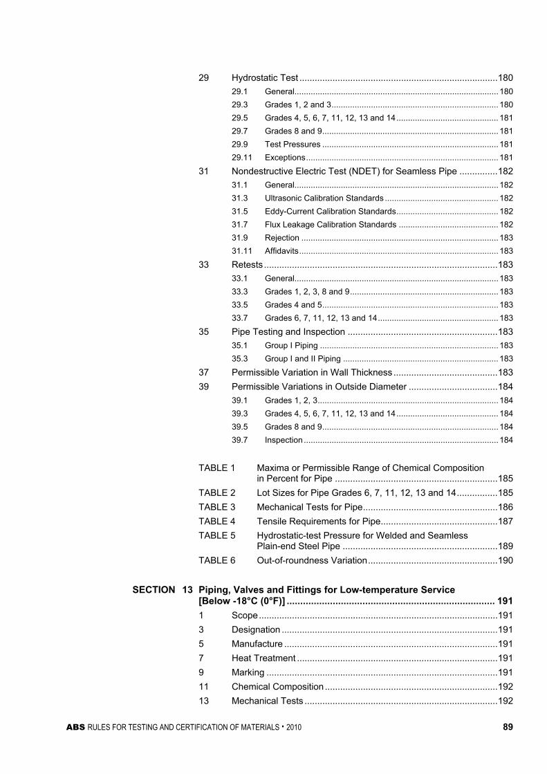
ABS RULES FOR TESTING AND CERTIFICATION OF MATERIALS . 2010 89
29 Hydrostatic Test ..............................................................................180 29.1 General........................................................................................180 29.3 Grades 1, 2 and 3........................................................................ 180 29.5 Grades 4, 5, 6, 7, 11, 12, 13 and 14............................................ 181 29.7 Grades 8 and 9............................................................................ 181 29.9 Test Pressures ............................................................................ 181 29.11 Exceptions................................................................................... 181
31 Nondestructive Electric Test (NDET) for Seamless Pipe ...............182 31.1 General........................................................................................182 31.3 Ultrasonic Calibration Standards ................................................. 182 31.5 Eddy-Current Calibration Standards............................................ 182 31.7 Flux Leakage Calibration Standards ........................................... 182 31.9 Rejection ..................................................................................... 183 31.11 Affidavits...................................................................................... 183
33 Retests ............................................................................................183 33.1 General........................................................................................183 33.3 Grades 1, 2, 3, 8 and 9................................................................ 183 33.5 Grades 4 and 5............................................................................ 183 33.7 Grades 6, 7, 11, 12, 13 and 14.................................................... 183
35 Pipe Testing and Inspection ...........................................................183 35.1 Group I Piping ............................................................................. 183 35.3 Group I and II Piping ................................................................... 183
37 Permissible Variation in Wall Thickness .........................................183 39 Permissible Variations in Outside Diameter ...................................184
39.1 Grades 1, 2, 3..............................................................................184 39.3 Grades 4, 5, 6, 7, 11, 12, 13 and 14............................................ 184 39.5 Grades 8 and 9............................................................................ 184 39.7 Inspection ....................................................................................184
TABLE 1 Maxima or Permissible Range of Chemical Composition
in Percent for Pipe ................................................................185 TABLE 2 Lot Sizes for Pipe Grades 6, 7, 11, 12, 13 and 14................185 TABLE 3 Mechanical Tests for Pipe.....................................................186 TABLE 4 Tensile Requirements for Pipe..............................................187 TABLE 5 Hydrostatic-test Pressure for Welded and Seamless
Plain-end Steel Pipe .............................................................189 TABLE 6 Out-of-roundness Variation...................................................190
SECTION 13 Piping, Valves and Fittings for Low-temperature Service
[Below -18°C (0°F)] ............................................................................. 191 1 Scope..............................................................................................191 3 Designation .....................................................................................191 5 Manufacture ....................................................................................191 7 Heat Treatment ...............................................................................191 9 Marking ...........................................................................................191 11 Chemical Composition ....................................................................192 13 Mechanical Tests ............................................................................192
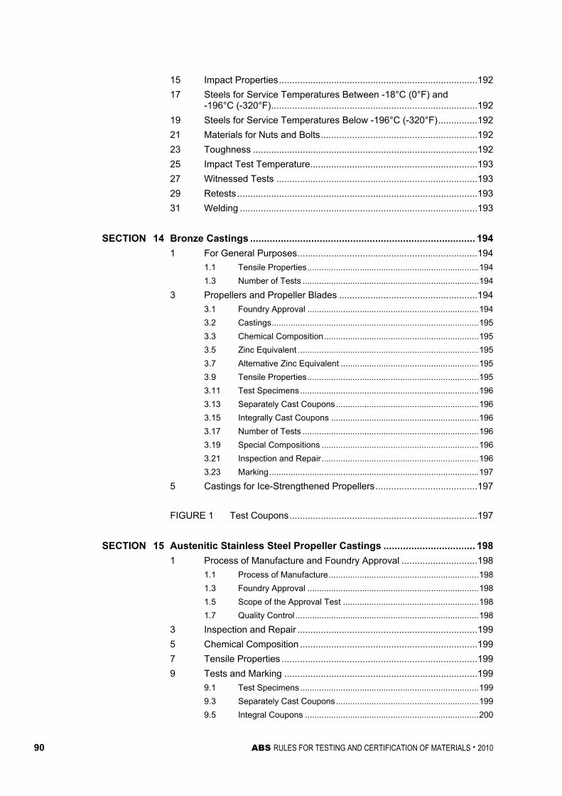
90 ABS RULES FOR TESTING AND CERTIFICATION OF MATERIALS . 2010
15 Impact Properties............................................................................192 17 Steels for Service Temperatures Between -18°C (0°F) and
-196°C (-320°F)...............................................................................192 19 Steels for Service Temperatures Below -196°C (-320°F)...............192 21 Materials for Nuts and Bolts............................................................192 23 Toughness ......................................................................................192 25 Impact Test Temperature................................................................193 27 Witnessed Tests .............................................................................193 29 Retests ............................................................................................193 31 Welding ...........................................................................................193
SECTION 14 Bronze Castings ................................................................................. 194
1 For General Purposes.....................................................................194 1.1 Tensile Properties........................................................................194 1.3 Number of Tests ..........................................................................194
3 Propellers and Propeller Blades .....................................................194 3.1 Foundry Approval ........................................................................194 3.2 Castings.......................................................................................195 3.3 Chemical Composition.................................................................195 3.5 Zinc Equivalent ............................................................................195 3.7 Alternative Zinc Equivalent ..........................................................195 3.9 Tensile Properties........................................................................195 3.11 Test Specimens...........................................................................196 3.13 Separately Cast Coupons............................................................196 3.15 Integrally Cast Coupons ..............................................................196 3.17 Number of Tests ..........................................................................196 3.19 Special Compositions ..................................................................196 3.21 Inspection and Repair..................................................................196 3.23 Marking........................................................................................197
5 Castings for Ice-Strengthened Propellers.......................................197 FIGURE 1 Test Coupons........................................................................197
SECTION 15 Austenitic Stainless Steel Propeller Castings ................................. 198
1 Process of Manufacture and Foundry Approval .............................198 1.1 Process of Manufacture...............................................................198 1.3 Foundry Approval ........................................................................198 1.5 Scope of the Approval Test .........................................................198 1.7 Quality Control .............................................................................198
3 Inspection and Repair .....................................................................199 5 Chemical Composition ....................................................................199 7 Tensile Properties ...........................................................................199 9 Tests and Marking ..........................................................................199
9.1 Test Specimens...........................................................................199 9.3 Separately Cast Coupons............................................................199 9.5 Integral Coupons .........................................................................200

ABS RULES FOR TESTING AND CERTIFICATION OF MATERIALS . 2010 91
9.7 Number of Tests.......................................................................... 200 9.9 Special Compositions.................................................................. 200 9.11 Marking........................................................................................200
11 Castings for Ice-strengthened Propellers .......................................200 SECTION 16 Seamless Copper Piping ................................................................... 201
1 Scope..............................................................................................201 3 General ...........................................................................................201
3.1 Grades C1, C2, C3, C4, C5, C6 and C7...................................... 201 3.3 ASTM Designation ...................................................................... 201
5 Process of Manufacture ..................................................................201 7 Marking ...........................................................................................202
7.1 Manufacturer’s Marking............................................................... 202 7.3 Bureau Markings ......................................................................... 202
9 Chemical Composition ....................................................................202 11 Tension Test ...................................................................................202
11.1 Tension Test Specimens............................................................. 202 11.3 Tensile Properties ....................................................................... 202
13 Expansion Test ...............................................................................202 15 Flattening Test ................................................................................202 17 Hydrostatic Test ..............................................................................202
17.1 Limiting Test Pressures ............................................................... 202 17.3 Affidavits of Tests ........................................................................ 203
19 Number of Tests .............................................................................203 21 Retests ............................................................................................203 23 Permissible Variations in Dimensions.............................................203 TABLE 1 Chemical Composition for Copper Pipe and Tube ...............204 TABLE 2 Tensile Properties for Copper Pipe and Tube ......................204
SECTION 17 Seamless Red-brass Piping .............................................................. 205
1 Process of Manufacture ..................................................................205 3 Marking ...........................................................................................205
3.1 Manufacturer’s Marking............................................................... 205 3.3 Bureau Marking ........................................................................... 205
5 Scope..............................................................................................205 7 Chemical Composition ....................................................................205 9 Expansion Test ...............................................................................206 11 Flattening Test ................................................................................206 13 Mercurous Nitrate Test ...................................................................206 15 Bend Test........................................................................................206 17 Hydrostatic Test ..............................................................................206
17.1 Limiting Test Pressures ............................................................... 206 17.3 Affidavits of Tests ........................................................................ 206

92 ABS RULES FOR TESTING AND CERTIFICATION OF MATERIALS . 2010
19 Number of Tests .............................................................................207 21 Retests ............................................................................................207 23 Permissible Variations in Dimensions.............................................207
SECTION 18 Seamless Copper Tube...................................................................... 208
1 Scope..............................................................................................208 3 General ...........................................................................................208
3.1 Grades CA, CB, CC, CD, CE, CF and CG...................................208 3.3 ASTM Designation.......................................................................208
5 Process of Manufacture ..................................................................208 7 Marking ...........................................................................................209
7.1 Manufacturer’s Marking ...............................................................209 7.3 Bureau Markings..........................................................................209
9 Chemical Composition ....................................................................209 11 Tension Test ...................................................................................209
11.1 Tension Test Specimens .............................................................209 11.3 Tensile Properties........................................................................209
13 Expansion Test ...............................................................................209 15 Flattening Test ................................................................................209 17 Hydrostatic Test ..............................................................................209
17.1 Limiting Test Pressures ...............................................................209 17.3 Affidavits of Tests ........................................................................210
19 Number of Tests .............................................................................210 21 Retests ............................................................................................210 23 Permissible Variations in Dimensions.............................................210
SECTION 19 Condenser and Heat Exchanger Tube.............................................. 211
1 Scope..............................................................................................211 3 General ...........................................................................................211
3.1 Grades CNA and CNB.................................................................211 3.3 ASTM Designation.......................................................................211
5 Process of Manufacture ..................................................................211 5.1 Grade CNA ..................................................................................211 5.3 Grade CNB ..................................................................................211
7 Marking ...........................................................................................212 9 Chemical Composition ....................................................................212
9.1 Chemical Requirements ..............................................................212 9.3 Chemical Analysis Sampling .......................................................212
11 Tension Test ...................................................................................212 11.1 Tension Test Specimens .............................................................212 11.3 Tensile Properties........................................................................212
13 Expansion Test ...............................................................................212 15 Flattening Test ................................................................................212 17 Nondestructive Electric Test (NDET)..............................................213

ABS RULES FOR TESTING AND CERTIFICATION OF MATERIALS . 2010 93
19 Hydrostatic Test ..............................................................................213 19.1 Limiting Test Pressures ............................................................... 213 19.3 Affidavits of Tests ........................................................................ 213
21 Number of Tests .............................................................................214 23 Retests ............................................................................................214 25 Finish...............................................................................................214 27 Dimensions and Tolerances ...........................................................214
27.1 Diameter...................................................................................... 214 27.3 Wall Thickness Tolerances.......................................................... 215 27.5 Length ......................................................................................... 215 27.7 Squareness of Cut....................................................................... 215
TABLE 1 Chemical Composition for Copper Nickel Pipe and Tube ....216 TABLE 2 Tensile Properties for Seamless Copper Nickel Pipe and
Tube ......................................................................................216 SECTION 20 Copper-Nickel Tube and Pipe ........................................................... 217
1 Scope..............................................................................................217 3 General ...........................................................................................217
3.1 Grades CN1 and CN2 ................................................................. 217 3.3 Grades CN3 and CN4 ................................................................. 217 3.5 ASTM Designation ...................................................................... 217
5 Process of Manufacture ..................................................................217 5.1 Grades CN1 and CN2 ................................................................. 217 5.3 Grades CN3 and CN4 ................................................................. 218
7 Marking ...........................................................................................218 9 Chemical Composition ....................................................................218
9.1 Chemical Requirements .............................................................. 218 9.3 Chemical Analysis Sampling ....................................................... 218
11 Tension Test ...................................................................................218 11.1 Tension Test Specimens............................................................. 218 11.3 Seamless Tensile Properties....................................................... 218 11.5 Welded (WO61) Tensile Properties............................................. 218 11.7 Welded (WO50) Tensile Properties............................................. 219
13 Expansion Test ...............................................................................219 13.1 Grades CN1 and CN2 ................................................................. 219 13.3 Grades CN3 and CN4 ................................................................. 219
15 Flattening Test ................................................................................219 17 Nondestructive Examination ...........................................................219
17.1 Nondestructive Electric Test (NDET)........................................... 219 17.3 Radiographic Examination........................................................... 219
19 Hydrostatic Test ..............................................................................220 19.1 Limiting Test Pressures ............................................................... 220 19.3 Affidavits of Tests ........................................................................ 220
21 Number of Tests .............................................................................220 23 Retests ............................................................................................220

94 ABS RULES FOR TESTING AND CERTIFICATION OF MATERIALS . 2010
25 Finish...............................................................................................220 27 Dimensions and Tolerances ...........................................................221
27.1 Diameter ......................................................................................221 27.3 Roundness ..................................................................................221 27.5 Wall Thickness Tolerances..........................................................221 27.7 Length..........................................................................................221 27.9 Squareness of Cut .......................................................................222 27.11 Straightness Tolerances ..............................................................222
SECTION 21 Monel Pipe and Tube.......................................................................... 223
1 Scope..............................................................................................223 3 General ...........................................................................................223
3.1 Grades M1 and M2......................................................................223 3.3 Grades M3 and M4......................................................................223 3.5 ASTM Designation.......................................................................223
5 Process of Manufacture ..................................................................223 5.1 Grades M1 and M2......................................................................223 5.3 Grades M3 and M4......................................................................224
7 Marking ...........................................................................................224 9 Chemical Composition ....................................................................224
9.1 Ladle Analysis .............................................................................224 9.3 Chemical Composition – Check Analysis ....................................224
11 Tension Test ...................................................................................225 11.1 Tension Test Specimens .............................................................225 11.3 Annealed Tensile Properties........................................................225 11.5 Stress Relieved Tensile Properties..............................................225
13 Flattening Test ................................................................................225 15 Flare Test ........................................................................................225 17 Flange Test .....................................................................................225 19 Number of Tests .............................................................................226
19.1 Chemical Analysis .......................................................................226 19.3 Other Tests..................................................................................226
21 Hydrostatic Test ..............................................................................226 21.1 Limiting Test Pressures ...............................................................226 21.3 Exceeding Limiting Test Pressures..............................................227 21.5 Affidavits of Tests ........................................................................227
23 Nondestructive Electric Test (NDET)..............................................227 23.1 General........................................................................................227 23.3 Ultrasonic Calibration Standards .................................................227 23.5 Eddy-Current Calibration Standards ............................................227 23.7 Rejection......................................................................................227 23.9 Affidavits ......................................................................................227
25 Retests ............................................................................................228 27 Finish...............................................................................................228

ABS RULES FOR TESTING AND CERTIFICATION OF MATERIALS . 2010 95
29 Dimensions and Tolerances ...........................................................228 29.1 Diameter...................................................................................... 228 29.3 Wall Thickness – Seamless......................................................... 228 29.5 Wall Thickness – Welded ............................................................ 229 29.7 Cut Ends...................................................................................... 229 29.9 Straightness ................................................................................ 229

96 ABS RULES FOR TESTING AND CERTIFICATION OF MATERIALS . 2010
P A R T S e c t i o n 1 : G e n e r a l R e q u i r e m e n t s
2 C H A P T E R 3 Materials for Machinery, Boilers, Pressure
Vessels, and Piping
S E C T I O N 1 General Requirements
1 Testing and Inspection
1.1 General (2007) All materials subject to test and inspection, intended for use in boilers, pressure vessels, piping and machinery of vessels classed or proposed for classification, are to be verified by the Surveyor in accordance with the following requirements or their equivalent. Materials, test specimens, and testing procedures having characteristics differing from those prescribed herein require special approval for each application of such materials and the physical tests may be modified to suit conditions as approved in connection with the design.
1.3 Test and Test Data 1.3.1 Witnessed Tests
The designation (W) indicates that the Surveyor is to witness the testing unless the plant and product is approved under the Bureau’s Quality Assurance Program.
1.3.2 Manufacturer’s Data The designation (M) indicated that test data is to be provided by the manufacturer without verification by a Surveyor of the procedures used or the results obtained.
1.3.3 Other Tests The designation (A) indicates those tests for which test data is to be provided by the supplier and audited by the Surveyor to verify that the procedures used and random tests witnessed are in compliance with Rule requirements.
See Part 2, Appendix 1 for the complete listing of indicated designations for the various tests called out by Part 2, Chapter 3.
1.5 Rejection of Previously Accepted Material In the event of any material proving unsatisfactory in the process of being worked, it is to be rejected, notwithstanding any previous certificate of satisfactory testing.
1.7 Calibrated Testing Machines (2005) The Surveyor is to be satisfied that the testing machines are maintained in a satisfactory and accurate condition and is to keep a record of the dates and by whom the machines were rechecked or calibrated. All tests are to be carried out to a recognized national or international Standard by competent personnel.
1.9 ASTM References For identification of ASTM references, see 2-1-1/1.13.
Part 2 Rules for Materials and Welding Chapter 3 Materials for Machinery, Boilers, Pressure Vessels and Piping Section 1 General Requirements 2-3-1
ABS RULES FOR TESTING AND CERTIFICATION OF MATERIALS . 2010 97
3 Defects All materials are to be free from cracks, injurious surface flaws, injurious laminations and similar defects. Except as indicated for specific materials, welding or dressing for the purpose of remedying defects is not permitted unless and until sanctioned by the Surveyor. In such cases, where sanction is required for materials to be so treated, the Surveyor may prescribe further probing and necessary heat treatment; then, if found satisfactory, the part treated is to be stamped with the Surveyor’s identification mark and surrounded by a ring of paint.
5 Identification of Materials The manufacturer is to adopt a system of marking ingots, slabs, finished plates, shapes, castings and forgings which will enable the material to be traced to its original heat; and the Surveyor is to be given every facility for so tracing material.
7 Manufacturer’s Certificates
7.1 Form of Certificate Unless requested otherwise, four copies of the certified mill test reports and shipping information (may be separate or combined documents) of all accepted material indicating the grade of steel, heat identification numbers, test results and weight shipped are to be furnished to the Surveyor. One copy of the mill test report is to be endorsed by the Surveyor and forwarded to the Purchaser, and three are to be retained for the use of the Bureau. Before the certified mill test reports and shipping information are distributed to the local Bureau office, the manufacturer is to furnish the Surveyor with a certificate stating that the material has been made by an approved process and that it has satisfactorily withstood the prescribed tests. The following form of certificate will be accepted if printed on each certified mill test report with the name of the firm and initialed by the authorized representative of the manufacturer: “We hereby certify that the material described herein has been made to the applicable specification by the _________ process (state process) and tested in accordance with the requirements of _______________ (the American Bureau of Shipping Rules or state other specification) with satisfactory results.” At the request of manufacturers, consideration may be given to modifications in the form of the certificate, provided it correspondingly indicates compliance with the requirements of the Rules to no less degree than indicated in the foregoing statement.
7.3 Other Certificates Where steel is not produced in the works at which it is rolled or forged, a certificate is to be supplied to the Surveyor stating the process by which it was manufactured, the name of the manufacturer who supplied it and the number of the heat from which it was made. The number of the heat is to be marked on each plate or bar for the purpose of identification.
9 Marking and Retests
9.1 Identification of Test Specimens Where test specimens are required to be selected by the Surveyor, they are not to be detached until stamped with his identification mark; but in no case, except as otherwise specified, are they to be detached until the material has received its final treatment. Satisfactory Bureau-tested material is to be stamped AB, or as specified for a particular material, to indicate compliance with the requirements.
9.3 Defects in Specimens If any test specimen shows defective machining or develops defects, it may be discarded and another specimen substituted, except that for forgings, a retest is not allowed if a defect develops during testing which is caused by rupture, cracks, or flakes in the steel.

Part 2 Rules for Materials and Welding Chapter 3 Materials for Machinery, Boilers, Pressure Vessels and Piping Section 1 General Requirements 2-3-1
98 ABS RULES FOR TESTING AND CERTIFICATION OF MATERIALS . 2010
9.5 Retests (2005) The elongation value is, in principle, valid only if the distance between the fracture and the nearest gauge mark is not less than one-third of the original gauge length. However, the result is valid irrespective of the location of the fracture if the percentage elongation after fracture is equal to or greater than the required value.
Generally, elongation, A5, is determined on a proportional gauge length, dS 565.5 0 = , but may also be given for other specified gauge lengths.
If the material is a ferritic steel of low or medium strength and not cold worked, and the elongation is measured on a non-proportional gauge length, the required elongation, A0, on that gauge length, L0, may after agreement be calculated from the following formula:
40.0
0
050 2
⎟⎟
⎠
⎞
⎜⎜
⎝
⎛=
LS
AA
9.7 Rejected Material In the event that any set of test specimens fails to meet the requirements, the material from which such specimens have been taken are to be rejected and the required markings withheld or obliterated.
11 Standard Test Specimens
11.1 General Test specimens are to be taken longitudinally and of the full thickness or section of material as rolled, except as otherwise specified.
11.3 Test Specimens (2005) Test specimens are to receive no other preparation than that prescribed and are to similarly and simultaneously receive all of the treatment given the material from which they are cut, except as otherwise specified. Straightening of specimens distorted by shearing is to be carried out while the piece is cold. The accuracy of the tensile test machines is to be within ±1% of the load.
11.5 Tension Test Specimens for Plates and Shapes Tension test specimens for rolled plates, shapes and flats are to be cut from the finished material and machined to the form and dimensions shown in 2-3-1/Figure 1, or they may be prepared with both edges parallel throughout their length. Alternatives to the foregoing are indicated under specific materials.
11.7 Tension Test Specimens for Castings (Other than Gray Cast Iron) and Forgings (2006) Tension test specimens for castings (other than gray cast iron) and forgings are to be machined to the form and dimensions shown for the round specimen alternative C in 2-3-1/Figure 1 or in accordance with 2-3-1/Figure 2.
11.9 Tension Test Specimens (for Gray Cast Iron) (2006) Tension test specimens for gray cast iron are, unless otherwise approved, to be machined to the form and dimensions shown in 2-3-1/Figure 3 from test bars cast separately from the casting represented. Such test bars are to be poured from ladles of iron used to pour the castings and under the same sand conditions, and they are to receive the same thermal treatment as the castings they represent.
11.11 Transverse or Flexure Test Specimens for Gray Cast Iron (2006) Transverse or flexure test specimens for gray cast iron are, unless otherwise approved, to be a test bar as cast with a 50 mm (2 in.) diameter and 700 mm (27 in.) length. Such test bars are to be cast under the same conditions as described in 2-3-1/11.9.

Part 2 Rules for Materials and Welding Chapter 3 Materials for Machinery, Boilers, Pressure Vessels and Piping Section 1 General Requirements 2-3-1
ABS RULES FOR TESTING AND CERTIFICATION OF MATERIALS . 2010 99
11.13 Bend Test Specimens for Steel Castings and Forgings (2005) When required, bend test specimens for steel castings and forgings may be machined to 25 mm × 20 mm (1 in. × 0.790 in.) in section. The length is unimportant, provided that it is enough to perform the bending operation.
The edges on the tensile side of the bend test specimens may have the corners rounded to a radius of 1–2 mm (0.040–0.080 in.).
FIGURE 1 Standard Tension Test Specimen (1) (2006)
d a b
Lo
Lc
A
R
= diameter in mm = thickness in mm = width in mm = original gauge length in mm = parallel length in mm = original cross sectional area in mm2 = transition radius in mm
Round Specimen
Flat Specimen
A
A
O
R
R
d
b
a
L
L C
d a b Lo Lc R Flat specimen Alternative A
– t (2) 25 5.65 A Lo + 2 A 25
Flat specimen Alternative B
– t (2) 25 200 225 25
Round specimen Alternative C
14 – – 70 85 10
Notes:
1 Standard specimen in accordance with ASTM E8/E8M or A370 will also be acceptable in conjunction with the corresponding elongation requirements in 2-1-2/Table 2 or 2-1-3/Table 2.
2 t is the full thickness of the material as produced. If the capacity of the testing machine does not allow full thickness specimens to be broken, the thickness may be reduced by machining one surface only.
3 Lo, the proportional gauge length, is to be greater than 20 mm.

Part 2 Rules for Materials and Welding Chapter 3 Materials for Machinery, Boilers, Pressure Vessels and Piping Section 1 General Requirements 2-3-1
100 ABS RULES FOR TESTING AND CERTIFICATION OF MATERIALS . 2010
FIGURE 2 Standard Round Tension Test Specimen with 50 mm (2 in.) Gauge Length (2008)
50 mm ± 0.125 mm(2 in. ± 0.005 in.)
10 mm ± 0.25 mm(0.375 in. ± 0.010 in.)
Reduced Section60 mm (2.25 in.) min.
Radius 10 mm(0.375 in.) min.
Gauge length for measuringelongation after fracture
Note: (2008) The gauge length and fillets are to be as shown, but the ends may be of any shape to fit the holders of the testing machine in such a way that the load is to be axial. The reduced section may have a gradual taper from the ends towards the center, with the ends not more than 0.13 mm (0.005 in.) larger in diameter than the center.
FIGURE 3 Tension Test Specimen Machined from Transverse
or Flexure Test Bars for Gray Cast Iron (2006)
+R = 25
20 mm dia.
13 Definition and Determination of Yield Point and Yield Strength
13.1 Yield Point (2005) The yield point is the first stress in a material, less than the maximum obtainable stress, at which an increase in strain occurs without an increase in stress. The value of stress is measured at the commencement of plastic deformation at yield, or the value of stress measured at the first peak obtained during yielding even when that peak is equal to or less than any subsequent peaks observed during plastic deformation at yield. Yield point may be determined by the halt of the pointer or autographic diagram. The 0.5% total extension under load method will also be considered acceptable.
The test is to be carried out with an elastic stress within the following limits:
Rate of Stressing, N/mm2-s-1 Modulus of Elasticity of the Material (E), N/mm2 Min. Max.
< 150,000 2 20 ≥ 150,000 6 60

Part 2 Rules for Materials and Welding Chapter 3 Materials for Machinery, Boilers, Pressure Vessels and Piping Section 1 General Requirements 2-3-1
ABS RULES FOR TESTING AND CERTIFICATION OF MATERIALS . 2010 101
13.3 Yield Strength (2005) The yield strength is the stress at which a material exhibits a specified limiting deviation from the proportionality of stress to strain. When no well-defined yield phenomenon exists, yield strength is to be determined by the 0.2% (Rp 0.2) offset method. Alternatively, for material whose stress-strain characteristics are well known from previous tests in which stress-strain diagrams were plotted, the 0.5% extension under load method may be used. When agreed upon between the supplier and purchaser for austenitic and duplex stainless steel products, the 1% proof stress (Rp 1) may be determined in addition to Rp 0.2.
The rate of loading is to be as stated in the limits above:
13.5 Tensile Strength (2005) After reaching the yield or proof load, for ductile material, the machine speed during the tensile test is not to exceed that corresponding to a strain rate of 0.008 s-1. For brittle materials, such as gray cast iron, the elastic stress rate is not to exceed 10 N/mm2 per second.
15 Permissible Variations in Dimensions (1994)
15.1 Scope The under tolerance specified below represents the minimum material certification requirements and is to be considered as the lower limit of usual range of variations (plus/minus) from the specified dimension. The responsibility for meeting the specified tolerances rests with the manufacturer who is to maintain a procedure acceptable to the Surveyor.
15.3 Plates (1996) The maximum permissible under thickness tolerance for plates and wide flats for construction of machinery, excluding boilers, pressure vessels and independent tanks for liquefied gases and chemicals (see 2-3-2/1.15), is to be in accordance with the following:
Nominal Thickness, t, in mm (in.) Under Thickness Tolerance in mm. (in.)
5 ≤ t < 8 mm (0.20 ≤ t < 0.32 in.) 0.4 mm (0.016 in.)
8 ≤ t < 15 mm (0.32 ≤ t < 0.59 in.) 0.5 mm (0.02 in.)
15 ≤ t < 25 mm (0.59 ≤ t < 0.98 in.) 0.6 mm (0.024 in.)
25 ≤ t < 40 mm (0.98 ≤ t < 1.57 in.) 0.8 mm (0.032 in.)
t ≥ 40 mm (t ≥ 1.57 in.) 1.0 mm (0.04 in.)
The thickness is to be measured at a distance of 10 mm (0.375 in.) or more from the edge.
The under thickness tolerance for plates and wide flats less than 5 mm (0.20 in.) in thickness will be specially considered.

102 ABS RULES FOR TESTING AND CERTIFICATION OF MATERIALS . 2010
P A R T Section 2:Steel Plates for Machinery, Boilers and Pressure Vessels
2 C H A P T E R 3 Materials for Machinery, Boilers, Pressure
Vessels, and Piping
S E C T I O N 2 Steel Plates for Machinery, Boilers and Pressure Vessels
1 General Requirements for All Grades of Steel Plates for Machinery, Boilers, and Pressure Vessels
1.1 General 1.1.1 Examination at Mills (2008)
The grades of steel covered in 2-3-2/3, 2-3-2/5 and 2-3-2/7 are rolled plates intended for use in machinery, boilers and other pressure vessels. All tests are to be conducted in the presence of the Surveyor at the place of manufacture prior to shipping, unless the plant is approved under the Bureau’s Quality Assurance Program for Rolled Products. The material surfaces will be examined by the Surveyor when specially requested by the purchaser. Plates are to be free from defects and have a workmanlike finish, subject to the conditions given under 2-3-2/1.17.
1.1.2 Alloy Steels or Special Carbon Steels When alloy steels or carbon steels differing from those indicated herein are proposed for any purpose, the purchaser’s specification is to be submitted for approval in connection with the approval of the design for which the material is proposed. Specifications such as ASTM A387 (Grade C or Grade D) or other steels suitable for the intended service will be considered.
1.3 Marking 1.3.1 Plates and Test Specimens
The name or brand of the manufacturer, the letter indicating the grade of steel, the manufacturer’s identification numbers and the letters PV to indicate pressure-vessel quality are to be legibly stamped (except as specified in 2-3-2/1.3.4) on each finished plate in two places, not less than 300 mm (12 in.) from the edges. Plates, the maximum lengthwise and crosswise dimensions of which do not exceed 1800 mm (72 in.), are to have the marking stamped in one place approximately midway between the center and an edge. The manufacturer’s test identification number is to be legibly stamped on each test specimen. All test specimens are to be ring-stamped, match-marked or otherwise suitably identified to the satisfaction of the attending Surveyor before being detached.
1.3.2 Heat-treatment Marking When the heat treatment is to be carried out by the fabricator as covered in 2-3-2/5.5 and 2-3-2/7.5, the letter G is to also be stamped on each plate by the steel producer to indicate that the material is in the unheat-treated (green) condition. After heat treatment at the fabricator’s plant, the letter T is to be stamped following the letter G.

Part 2 Rules for Materials and Welding Chapter 3 Materials for Machinery, Boilers, Pressure Vessels and Piping Section 2 Steel Plates for Machinery, Boilers and Pressure Vessels 2-3-2
ABS RULES FOR TESTING AND CERTIFICATION OF MATERIALS . 2010 103
1.3.3 Bureau Markings The Bureau markings AB, indicating satisfactory compliance with the Rule requirements and other markings as furnished by the Surveyor, are to be stamped on all plates near the marking specified in 2-3-2/1.3.1 to signify that the material has satisfactorily complied with the test prescribed, and that certificates for the material will be furnished to the Surveyor in accordance with 2-3-1/7. For coiled steel which is certified for chemical analysis only, the marking AB without grade designation is to be marked on the outer wrap of each coil shipped.
1.3.4 Thin Plates Plates under 6.4 mm (0.25 in.) in thickness are to be legibly stenciled with the markings specified in 2-3-2/1.3.1 and 2-3-2/1.3.2 instead of stamped.
1.3.5 Special Impact Testing When steel is impact tested in accordance with 2-3-2/9, the grade marking is to be followed by the test temperature in degrees Celsius. A prefix “0” to the test temperature is to indicate a temperature colder than zero degrees Celsius.
1.5 Process of Manufacture The steel is to be made by one or more of the following processes: open-hearth, basic-oxygen or electric-furnace. The steel may be cast in ingots or may be strand (continuous) cast. The ratio of reduction of thickness from strand (continuous) cast slab to finished plate is to be a minimum of 3 to 1 unless specially approved.
1.5.1 Plates Produced from Coils For coiled plate, the manufacturer or processor is to submit supporting data for review and approval to indicate that the manufacturing, processing and testing will provide material which is in compliance with the Rules.
1.7 Chemical Composition 1.7.1 Ladle Analysis
An analysis of each heat of steel is to be made by the manufacturer to determine the percentage of the elements specified. This analysis is to be made from a test sample taken during pouring of the heat. The chemical composition thus determined is to be reported to the Surveyor and is to conform to the requirements as specified for each grade in 2-3-2/3.5, 2-3-2/5.7 or 2-3-2/7.7.
1.7.2 Check Analysis The chemical composition determined by check analysis is to conform to the requirements as specified for each Grade in 2-3-2/3.5, 2-3-2/5.7, and 2-3-2/7.7.
1.9 Test Specimens 1.9.1 Selection of Specimens
One tension test specimen is to be taken from each plate as rolled in such manner that the longitudinal axis of the specimen is transverse to the final direction of rolling of the plate. The tension test specimen is to be taken from a corner of the plate. If the final rolling direction of the plate is parallel to the original longitudinal ingot axis, the tension test specimen is to be taken from the “bottom” end of the plate. If the final direction of rolling of the plate is transverse to the original longitudinal ingot axis, or if the relationship of final rolling direction and original ingot axis is unknown, the tension test specimen may be taken from either end. For plates produced from coils, two tension test specimens are to be made from each coil. One tension test specimen is to be obtained from a location immediately prior to the first plate produced and a second test specimen obtained from the approximate center lap. When required, impact tests are to be obtained adjacent to both tension test coupons and a third coupon is to be obtained immediately after the last plate produced to the qualifying grade or specification.

Part 2 Rules for Materials and Welding Chapter 3 Materials for Machinery, Boilers, Pressure Vessels and Piping Section 2 Steel Plates for Machinery, Boilers and Pressure Vessels 2-3-2
104 ABS RULES FOR TESTING AND CERTIFICATION OF MATERIALS . 2010
1.9.2 Specimens from Plates 19 mm (0.75 in.) and Under in Thickness For plates 19 mm (0.75 in.) and under in thickness, tension test specimens are to be the full thickness of the material and are to be machined to the form and dimensions shown in 2-3-1/Figure 1 or with both edges parallel.
1.9.3 Specimens from Plates Over 19 mm (0.75 in.) Thickness For plates over 19 mm (0.75 in.) in thickness, tension test specimens may be machined to the form and dimensions shown in 2-3-1/Figure 2, and the axis of each such specimen is to be located as nearly as practicable midway between the center and the surface of the plate, or for plates up to 101.6 mm (4 in.) inclusive in thickness, they may be the full thickness of the material and of the form shown in 2-3-1/Figure 1 when adequate testing-machine capacity is available.
1.9.4 Stress Relieving When required, test specimens are to be stress-relieved by gradually and uniformly heating them to 590–650°C (1100–1200°F), holding at temperature for at least 1 hour per 25 mm (1 in.) thickness and cooling in still atmosphere to a temperature not exceeding 315°C (600°F). If applicable, in the case of plates which are to be heat-treated and subsequently stress-relieved, the test specimens for such plates are to, before testing, be stress-relieved following the heat treatment.
1.11 Tensile Properties 1.11.1 Tensile Requirements
The material is to conform to the tensile requirements as specified for each grade in 2-3-2/3.9, 2-3-2/5.11 or 2-3-2/7.11.
1.11.2 Elongation Deduction for Material Under 7.9 mm (0.313 in.) Thick For material under 7.9 mm (0.313 in.) in thickness, a deduction from the specified percentage of elongation in 200 mm (8 in.) of 1.25% is to be made for each decrease of 0.8 mm (0.031 in.) of the specified thickness below 7.9 mm (0.313 in.).
1.11.3 Elongation Deduction for Material Over 88.9 mm (3.50 in.) Thick For material over 88.9 mm (3.50 in.) in thickness, a deduction from the specified percentage of elongation in 50 mm (2 in.) of 0.50% is to be made for each increase of 12.7 mm (0.50 in.) of the specified thickness above 88.9 mm (3.50 in.). This deduction is not to exceed 3%.
1.13 Retests 1.13.1 For All Thicknesses
When the result of any of the physical tests specified for any of the material does not conform to the requirements, two additional specimens may, at the request of the manufacturer, be taken from the same plate and tested in the manner specified, but in such case, both of the specimens are to conform to the requirements (see 2-3-1/9.5).
1.13.2 For Heat-treated Material (2008) If any heat-treated material fails to meet the mechanical requirements, the material may be reheat-treated, and all physical tests are to be repeated. Where plates are specially ordered requiring surface inspection, the Surveyor is to reexamine the plate surfaces following any additional heat treatment.
1.15 Thickness Variation No plate is to vary more than 0.25 mm (0.01 in.) or 6% under the thickness specified, whichever is the lesser (See 4-4-1A1/1.7).
1.17 Finish Except when ordered for riveted construction, plates may be conditioned by the manufacturer, for the removal of surface defects on either surface by grinding, provided the ground area is well faired and grinding does not reduce the thickness of the plate below the permissible minimum thickness.

Part 2 Rules for Materials and Welding Chapter 3 Materials for Machinery, Boilers, Pressure Vessels and Piping Section 2 Steel Plates for Machinery, Boilers and Pressure Vessels 2-3-2
ABS RULES FOR TESTING AND CERTIFICATION OF MATERIALS . 2010 105
1.19 Weldability All of the grades covered in 2-3-2/3, 2-3-2/5 and 2-3-2/7 are intended for fusion welding, but welding technique is of fundamental importance and the welding procedure is to be in accordance with approved methods. See Part 2, Chapter 4.
3 Steel Plates for Intermediate-temperature Service
3.1 Scope Three grades of low and intermediate-tensile-strength carbon-steel plates designated MA, MB, and MC are covered.
3.3 General The various grades are in substantial agreement with ASTM designations as follows.
ASTM – A285 Grades A, B, C
ABS – Grades MA, MB, MC
The maximum thickness of these grades is to be 50.8 mm (2.0 in.).
3.5 Chemical Composition The steel is to conform to the following requirements as to chemical composition.
Grade MA Grade MB Grade MC Carbon, max., % 0.17 0.22 0.28 Manganese, max., % 0.90 0.90 0.90 Phosphorus, max., % 0.035 0.035 0.035 Sulfur, max., % 0.045 0.045 0.045 Copper*, when Copper Steel is specified Ladle Analysis 0.20/0.35 0.20/0.35 0.20/0.35 Check Analysis 0.18/0.37 0.18/0.37 0.18/0.37
Note: See 2-3-2/1.7.
* When specified, the maximum incidental copper content is to be 0.25%.
3.7 Specimen Preparation Test specimens are to be prepared for testing from material in its rolled condition.
3.9 Tensile Properties The material is to conform to the following requirements as to tensile properties.
Grade MA Grade MB Grade MC Tensile Strength N/mm2 (kgf/mm2) (psi) 310–450
(31.5–46) (45000–65000)
345–485 (35–49)
(50000–70000)
380–515 (39–53)
(55000–75000) Yield Strength, min., N/mm2 (kgf/mm2, psi) 165
(17, 24000) 185
(19, 27000) 205
(21, 30000) Elongation in 200 mm (8 in.) min., %* 27 25 23 Elongation in 50 mm (2 in.) min., % 30 28 27
* See 2-3-2/1.11.2 and 2-3-2/1.11.3.

Part 2 Rules for Materials and Welding Chapter 3 Materials for Machinery, Boilers, Pressure Vessels and Piping Section 2 Steel Plates for Machinery, Boilers and Pressure Vessels 2-3-2
106 ABS RULES FOR TESTING AND CERTIFICATION OF MATERIALS . 2010
5 Steel Plates for Intermediate- and Higher-temperature Service
5.1 Scope Seven grades of steel plates designated MD, ME, MF, MG, H, I and J are covered. Grades MD, ME, MF and MG cover intermediate and higher-tensile-strength ranges in carbon-silicon steel plates; Grades H, I and J cover three high-tensile-strength ranges in carbon-molybdenum steel plates.
5.3 General The various grades are in substantial agreement with ASTM designations as follows:
ASTM – A515 Grades 55, 60, 65, 70 ABS – Grades MD, ME, MF, MG
ASTM – A204 Grades A, B, C ABS – Grades H, I, J
Plates are limited in thickness as follows: Grade MD to 304.8 mm (12.0 in.); Grades ME, MF and MG to 203.2 mm (8.0 in.); Grades H and I to 152.4 mm (6.0 in.) and Grade J to 101.6 mm (4 in.).
5.5 Heat Treatment 5.5.1 Treatment
Plates of Grades MD, ME, MF and MG over 50.8 mm (2.0 in.) and Grades H, I and J over 38.1 mm (1.5 in.) in thickness are to be treated either by normalizing or heating uniformly for hot forming. If the required treatment is to be obtained in conjunction with the hot-forming operation, the temperature to which the plates are heated for hot forming is to be equivalent to and is not to significantly exceed the normalizing temperature. If this treatment is not done at the rolling mill, the testing is to be carried out in accordance with 2-3-2/5.5.3.
5.5.2 Heat-treatment Instructions on Orders Orders to the plate manufacturer or the fabricator are to specify when plates are to be heat-treated and any special requirement that the test specimens be stress-relieved, so that proper provision may be made for the heat treatment of the test specimens. The purchaser is to also indicate in the orders to the mill whether the rolling mill or the fabricator is to perform the required heat treatment of the plates.
5.5.3 Responsibility for Heat Treatment When a fabricator is equipped and elects to perform the required normalizing or fabricates by hot forming as provided in 2-3-2/5.5.1, the plates are to be accepted on the basis of tests made at the plate manufacturer’s plant on specimens heat-treated in accordance with the purchaser’s order requirements. If the heat-treatment temperatures are not indicated on the purchase order, the plate manufacturer is to heat-treat the specimens under conditions considered appropriate to meet the test requirements. The plate manufacturer is to inform the fabricator of the procedure followed in treating the specimens at the mill for guidance in treating the plates. When the plates are to be normalized at the plate manufacturer’s plant, the mechanical properties are to be determined on specimens simultaneously treated with the plates.
5.7 Chemical Composition The steel is to conform to the requirements of 2-3-2/Table 1 as to chemical composition.
5.9 Test Specimens 5.9.1 Plates Not Requiring Heat Treatment
For plates not requiring heat treatment (see 2-3-2/5.5.1), the test specimens are to be prepared for testing from the material in its rolled condition. When Grades H, I and J plates are to be used in a boiler or pressure vessel which is to be stress-relieved, the test specimens for Grades H, I and J are to be stress-relieved. See 2-3-2/1.9.

Part 2 Rules for Materials and Welding Chapter 3 Materials for Machinery, Boilers, Pressure Vessels and Piping Section 2 Steel Plates for Machinery, Boilers and Pressure Vessels 2-3-2
ABS RULES FOR TESTING AND CERTIFICATION OF MATERIALS . 2010 107
5.9.2 Plates Requiring Heat Treatment For plates requiring heat treatment (see 2-3-2/5.5.1), the test specimens are to be prepared from the material in its heat-treated condition, or from full-thickness samples similarly and simultaneously treated. When Grades H, I and J plates are to be used in a boiler or pressure vessel which is to be stress-relieved, the test specimens for Grades H, I and J are to be stress-relieved following the heat treatment. See 2-3-2/1.9 and 2-3-2/5.5.
5.11 Tensile Properties The material is to conform to the requirements of 2-3-2/Table 2 as to tensile properties.
7 Steel Plates for Intermediate- and Lower-temperature Service
7.1 Scope Four grades of carbon-manganese-silicon steel plates made to fine-grain practice in four tensile-strength ranges designated K, L, M, N are covered.
7.3 General The various grades are in substantial agreement with ASTM designations, as follows.
ASTM – A516 Grades 55, 60, 65, 70
ABS – Grades K, L, M, N
Plates are limited in thickness, as follows: Grade K to 304.8 mm (12.0 in.); Grades L, M and N to 203.2 mm (8.0 in.).
Materials for Liquefied Gas Carriers are to comply with Section 5C-8-6.
7.5 Heat Treatment 7.5.1 Grain Refinement
Plates over 38.1 mm (1.5 in.) are to be heat-treated to produce grain refinement either by normalizing or heating uniformly for hot forming. If the required treatment is to be obtained in conjunction with hot forming, the temperature to which the plates are heated for hot forming is to be equivalent to and is not to exceed significantly the normalizing temperature. If this treatment is not done at the rolling mill, the testing is to be carried out in accordance with 2-3-2/7.5.3. When improved notch toughness is required for plates 38 mm (1.5 in.) and under in thickness, heat treatment is to be specified as above.
7.5.2 Heat-treatment Instructions on Orders Orders to the plate manufacturer or the fabricator are to specify when plates are to be heat-treated for grain refinement, and any special requirements that the test specimens be stress-relieved, so that proper provision may be made for the heat treatment of the test specimens. The purchaser is also to indicate in the orders to the mill whether the rolling mill or the fabricator is to perform the required heat treatment of the plates.
7.5.3 Responsibility for Heat Treatment When a fabricator is equipped and elects to perform the required normalizing or fabricates by hot forming as provided in 2-3-2/7.5.1, the plates are to be accepted on the basis of tests made at the plate manufacturer’s plant on specimens heat-treated in accordance with the purchaser’s order requirements. If the heat-treatment temperatures are not indicated on the purchase order, the plate manufacturer is to heat-treat the specimens under conditions considered appropriate for grain refinement, and to meet the test requirements. The plate manufacturer is to inform the fabricator of the procedure followed in treating the specimens at the mill for guidance in treating the plates. When the plates are to be normalized at the plate manufacturer’s plant, the mechanical properties are to be determined on specimens simultaneously treated with the plates.
Part 2 Rules for Materials and Welding Chapter 3 Materials for Machinery, Boilers, Pressure Vessels and Piping Section 2 Steel Plates for Machinery, Boilers and Pressure Vessels 2-3-2
108 ABS RULES FOR TESTING AND CERTIFICATION OF MATERIALS . 2010
7.7 Chemical Composition The steel is to conform to the requirements of 2-3-2/Table 3 as to chemical composition.
7.9 Test Specimens 7.9.1 Plates 38.1 mm (1.5 in.) and Under in Thickness
For plates 38.1 mm (1.5 in.) and under in thickness, not requiring heat treatment, the test specimens are to be prepared for testing from the material in its rolled condition.
7.9.2 Plates Requiring Heat Treatment For plates 38.1 mm (1.5 in.) and under in thickness, requiring heat treatment (see 2-3-2/7.5.1), or for plates over 38.1 mm (1.5 in.) in thickness, the test specimens are to be prepared from the material in its heat-treated condition, or from full-thickness samples similarly and simultaneously treated.
7.11 Tensile Properties The material is to conform to the requirements of 2-3-2/Table 4 as to tensile properties.
9 Materials for Low Temperature Service [Below -18°C (0°F)] Materials intended for service temperatures of below -18°C (0°F) may be provided in accordance with those requirements listed in 2-1-4/9. Other special low temperature materials, when the Charpy V-notch impact tests are conducted at 5°C (10°F) below minimum design temperature in accordance with 2-1-4/5.1 and meet the applicable requirements of 2-1-2/11 and 5C-8-6/Table 2 (ABS) may also be accepted. Such tests are not required for austenitic stainless steels or aluminum alloys such as type 5083.

Part 2 Rules for Materials and Welding Chapter 3 Materials for Machinery, Boilers, Pressure Vessels and Piping Section 2 Steel Plates for Machinery, Boilers and Pressure Vessels 2-3-2
ABS RULES FOR TESTING AND CERTIFICATION OF MATERIALS . 2010 109
TABLE 1 Chemical Composition for Plate Grades MD, ME, MF, MG, H, I, J
Note See also 2-3-2/1.7 MD ME MF MG H I J Carbon, max., %: For plates 25.4 mm (1.0 in.) and under in thickness
0.20 0.24 0.28 0.31 0.18 0.20 0.23
For plates over 25.4 mm (1.0 in.) to 50.8 mm (2.0 in.) incl., in thickness
0.22 0.27 0.31 0.33 0.21 0.23 0.26
For plates over 50.8 mm (2.0 in.) to 101.6 mm (4.0 in.) incl., in thickness
0.24 0.29 0.33 0.35 0.23 0.25 0.28
For plates over 101.6 mm (4.0 in.) to 203.2 mm (8.0 in.) incl., in thickness
0.26 0.31 0.33 0.35 0.25 0.27
For plates over 203.2 mm (8.0 in.) to 304.8 mm (12.0 in.) incl., in thickness
0.28
Manganese, max., % 0.90 0.90 0.90 0.90 0.90 0.90 0.90 Phosphorous max., % 0.035 0.035 0.035 0.035 0.035 0.035 0.035 Sulphur, max., % 0.04 0.04 0.04 0.04 0.04 0.04 0.04 Silicon, %: Ladle analysis 0.15-0.30 0.15-0.30 0.15-0.30 0.15-0.30 0.15-0.30 0.15-0.30 0.15-0.30 Check analysis 0.13-0.33 0.13-0.33 0.13-0.33 0.13-0.33 0.13-0.32 0.13-0.32 0.13-0.32 Molybdenum, %: Ladle analysis 0.45-0.60 0.45-0.60 0.45-0.60 Check analysis 0.41-0.64 0.41-0.64 0.41-0.64
TABLE 2 Tensile Properties for Plate Grades MD, ME, MF, MG, H, I, J
A characteristic of certain types of alloy steels is a local, disproportionate increase in the degree of necking down or contraction of the specimens under tension tests, resulting in a decrease in the percentage of elongation as the gauge length is increased. The effect is not so pronounced in the thicker plates.
MD ME MF MG H I J Tensile Strength,
N/mm2 380-515 415-550 450-585 485-620 450-585 485-620 515-655 kgf/mm2 39-53 42-56 46-60 49-63 46-60 49-63 53-67 psi 55000-75000 60000-80000 65000-85000 70000-90000 65000-85000 70000-90000 75000-95000
Yield Strength, min., N/mm2 205 220 240 260 255 275 295 kgf/mm2 21 22.5 24.5 27 26 28 30.5 psi 30000 32000 35000 38000 37000 40000 43000
Elongation in 200 mm, (8 in.), min., % 23 (a) 21 (a) 19 (a) 17 (a) 19 (a,d) 17 (a,d) 16 (a,d) Elongation in 50 mm, (2 in.) min., % (c) 27 (b) 25 (b) 23 (b) 21 (b) 23 (b) 21 (b) 20 (b)
Notes a See 2-3-2/1.11.2
b See 2-3-2/1.11.3
c When specimen shown in 2-3-1/Figure 2 is used.
d For plates over 6.4 mm (0.25 in.) to 19.1 mm (0.75 in.) inclusive, in thickness, if the percentage of elongation of a 200 mm (8 in.) gauge-length test specimen falls not more than 3% below the amount specified, the elongation is to be considered satisfactory, provided the percentage of elongation in 50 mm (2 in.) across the break is not less than 25%.

Part 2 Rules for Materials and Welding Chapter 3 Materials for Machinery, Boilers, Pressure Vessels and Piping Section 2 Steel Plates for Machinery, Boilers and Pressure Vessels 2-3-2
110 ABS RULES FOR TESTING AND CERTIFICATION OF MATERIALS . 2010
TABLE 3 Chemical Composition for Plate Grades K, L, M, N
Note See also 2-3-2/1.7 K L M N Carbon, max., %: For plates 12.7 mm (0.50 in.) and under in thickness 0.18 0.21 0.24 0.27 Over 12.7 mm (0.50 in.) to 50.8 mm (2.0 in.) incl. 0.20 0.23 0.26 0.28 Over 50.8 mm (2.0 in.) to 101.6 mm (4.0 in.) incl. 0.22 0.25 0.28 0.30 Over 101.6 mm (4.0 in.) to 203.2 mm (8.0 in.) incl. 0.24 0.27 0.29 0.31 Over 203.2 mm (8.0 in.) to 304.8 mm (12.0 in.) incl. 0.26 Manganese, %: For plates 12.7 mm (0.50 in.) and under in thickness
Ladle 0.60/0.90 0.60/0.90 0.85/1.20 0.85/1.20 Check 0.56/0.94 0.56/0.94 0.80/1.25 0.80/1.25
Over 12.7 mm (0.50 in.) to 304.8 mm (12.0 in.) incl Ladle 0.60/1.20 0.85/1.20 0.85/1.20 0.85/1.20 Check 0.56/1.25 0.80/1.25 0.80/1.25 0.80/1.25
Phosphorus, max., % 0.035 0.035 0.035 0.035 Sulphur, max., % 0.04 0.04 0.04 0.04 Silicon, %:
Ladle 0.15/0.30 0.15/0.30 0.15/0.30 0.15/0.30 Check 0.13/0.33 0.13/0.33 0.13/0.33 0.13/0.33
TABLE 4 Tensile Properties for Plate Grades K, L, M, N
K L M N Tensile Strength,
N/mm2 380-515 415-550 450-585 485-620 kgf/mm2 39 to 53 42 to 56 46 to 60 49 to 63 psi 55000-75000 60000-80000 65000-85000 70000-90000
Yield Strength, min., N/mm2 205 220 240 260 kgf/mm2 21 22.5 24.5 27 psi 30000 32000 35000 38000
Elongation in 200 mm, (8 in.), min., % 23 (a) 21 (a) 19 (a) 17 (a) Elongation in 50 mm, (2 in.), min., % (c) 27 (b) 25 (b) 23 (b) 21 (b)
Notes: a See 2-3-2/1.11.2
b See 2-3-2/1.11.3
c When specimen shown in 2-3-1/Figure 2 is used.

ABS RULES FOR TESTING AND CERTIFICATION OF MATERIALS . 2010 111
P A R T S e c t i o n 3 : S e a m l e s s F o r g e d - s t e e l D r u m s
2 C H A P T E R 3 Materials for Machinery, Boilers, Pressure
Vessels, and Piping
S E C T I O N 3 Seamless Forged-steel Drums
Note: In substantial agreement with ASTM A266 as to physical properties for Classes 1 and 3.
1 Tests and Inspections In the event that any seamless forged-steel drums are presented for survey after special approval for each specific application, they are to be tested and surveyed in general accordance with the applicable procedures given for steel forgings. One tension test is to be taken from each end of the forging midway between the inner and outer surfaces of the wall in a tangential direction, the two specimens being taken from opposite sides of the drum. Grade A material is to have the following minimum properties, tensile strength 415 N/mm2 (42 kgf/mm2, 60,000 psi), yield strength 205 N/mm2 (21 kgf/mm2, 30,000 psi), elongation 23% in a 50 mm (2 in.) gauge length; Grade B material is to have the following minimum properties, tensile strength 515 N/mm2 (53 kgf/mm2, 75,000 psi), yield strength 260 N/mm2 (26.5 kgf/mm2, 37,500 psi), elongation 19% in a 50 mm (2 in.) gauge length.
3 Heat Treatment Except as specified herein, tests for acceptance are to be made after final treatment of the forgings. When the ends of drums are closed in by reforging after machining, the drums may be treated and tested prior to reforging. After reforging, the whole of the forging is to be simultaneously re-treated. If the original treatment was annealing, the re-anneal is to be above the transformation range, but not above the temperature of the first anneal. If the original treatment was normalizing and tempering, the re-treatment is to be identical with the original.

112 ABS RULES FOR TESTING AND CERTIFICATION OF MATERIALS . 2010
P A R T S e c t i o n 4 : S e a m l e s s - s t e e l P r e s s u r e V e s s e l s
2 C H A P T E R 3 Materials for Machinery, Boilers, Pressure
Vessels, and Piping
S E C T I O N 4 Seamless-steel Pressure Vessels
1 General The material for the manufacture of and the finished seamless pressure vessels are to be free from seams, cracks or other defects. Test specimens are to be cut from each cylinder before the necking-down process, stamped with the identification mark of the Surveyor and is to receive all heat treatments simultaneously with the cylinders.
3 Tension Test A standard test specimen cut either longitudinally or circumferentially from each cylinder is to show the material to have a minimum tensile strength of 415 N/mm2 (42 kgf/mm2, 60,000 psi), maximum yield point of 70% of the tensile strength and a minimum elongation of 10% in 200 mm (8 in.).
5 Flattening Test A ring 200 mm (8 in.) long is to be cut from each cylinder and is to stand being flattened without signs of fracture until the outside distance over the parallel sides is not greater than six times the thickness of the material.
7 Hydrostatic Test Each cylinder is to be subjected to a hydrostatic pressure of not less than one and one-half times the working pressure while submerged in a water jacket for a period of at least thirty seconds. The permanent volumetric expansion is not to exceed 5% of the total volumetric expansion at the prescribed test pressure. This test is to be made without previously subjecting the cylinder to any pressure in excess of one-third of the working pressure.
9 Inspection All cylinders are to be properly annealed and be free from dirt and scale. Before necking-down, the Surveyor is to examine the cylinders carefully for defects and gauge the cylinder walls to ascertain that the thickness of the material is in accordance with the approved plan.
11 Marking Upon satisfactory compliance with the above requirements, the cylinders will be stamped AB with the identification mark of the Surveyor, the serial number, hydrostatic pressure and the date of acceptance.

ABS RULES FOR TESTING AND CERTIFICATION OF MATERIALS . 2010 113
P A R T S e c t i o n 5 : B o i l e r a n d S u p e r h e a t e r T u b e s
2 C H A P T E R 3 Materials for Machinery, Boilers, Pressure
Vessels, and Piping
S E C T I O N 5 Boiler and Superheater Tubes
1 Scope (1998) The following specifications cover thirteen grades of boiler and superheater tubes designated D, F, G, H, J, K, L, M, N, O, P, R, and S.
3 General
3.1 Grades D and F Grades D and F cover electric-resistance-welded tubes made of carbon steel and intended for boiler tubes, boiler flues, superheater flues and safe ends. Grade F tubes are not suitable for safe-ending by forge-welding.
3.3 Grade G Grade G covers electric-resistance-welded, steel boiler and superheater tubes intended for high-pressure service.
3.5 Grade H Grade H covers seamless carbon-steel boiler tubes and superheater tubes intended for high-pressure service.
3.7 Grade J Grade J covers seamless medium carbon-steel boiler tubes and superheater tubes, boiler flues, including safe ends, arch and stay tubes. Grade J tubes are not suitable for safe-ending by forge-welding.
3.9 Grades K, L and M Grades K, L and M cover seamless carbon-molybdenum alloy-steel boiler and superheater tubes.
3.11 Grades N, O and P Grades N, O and P cover seamless chromium-molybdenum alloy-steel boiler and superheater tubes.
3.13 Grades R and S (1998) Grades R and S cover seamless austenitic stainless steel superheater tubes.
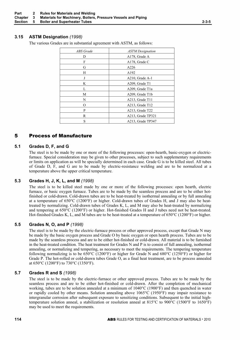
Part 2 Rules for Materials and Welding Chapter 3 Materials for Machinery, Boilers, Pressure Vessels and Piping Section 5 Boiler and Superheater Tubes 2-3-5
114 ABS RULES FOR TESTING AND CERTIFICATION OF MATERIALS . 2010
3.15 ASTM Designation (1998) The various Grades are in substantial agreement with ASTM, as follows:
ABS Grade ASTM Designation D A178, Grade A F A178, Grade C G A226 H A192 J A210, Grade A-1 K A209, Grade T1 L A209, Grade T1a M A209, Grade T1b N A213, Grade T11 O A213, Grade T12 P A213, Grade T22 R A213, Grade TP321 S A213, Grade TP347
5 Process of Manufacture
5.1 Grades D, F, and G The steel is to be made by one or more of the following processes: open-hearth, basic-oxygen or electric-furnace. Special consideration may be given to other processes, subject to such supplementary requirements or limits on application as will be specially determined in each case. Grade G is to be killed steel. All tubes of Grade D, F, and G are to be made by electric-resistance welding and are to be normalized at a temperature above the upper critical temperature.
5.3 Grades H, J, K, L, and M (1998) The steel is to be killed steel made by one or more of the following processes: open hearth, electric furnace, or basic oxygen furnace. Tubes are to be made by the seamless process and are to be either hot-finished or cold-drawn. Cold-drawn tubes are to be heat-treated by isothermal annealing or by full annealing at a temperature of 650°C (1200°F) or higher. Cold-drawn tubes of Grades H, and J may also be heat-treated by normalizing. Cold-drawn tubes of Grades K, L, and M may also be heat-treated by normalizing and tempering at 650°C (1200°F) or higher. Hot-finished Grades H and J tubes need not be heat-treated. Hot-finished Grades K, L, and M tubes are to be heat-treated at a temperature of 650°C (1200°F) or higher.
5.5 Grades N, O, and P (1998) The steel is to be made by the electric-furnace process or other approved process, except that Grade N may be made by the basic oxygen process and Grade O by basic oxygen or open hearth process. Tubes are to be made by the seamless process and are to be either hot-finished or cold-drawn. All material is to be furnished in the heat-treated condition. The heat treatment for Grades N and P is to consist of full annealing, isothermal annealing, or normalizing and tempering, as necessary to meet the requirements. The tempering temperature following normalizing is to be 650°C (1200°F) or higher for Grade N and 680°C (1250°F) or higher for Grade P. The hot-rolled or cold-drawn tubes Grade O, as a final heat treatment, are to be process annealed at 650°C (1200°F) to 730°C (1350°F).
5.7 Grades R and S (1998) The steel is to be made by the electric-furnace or other approved process. Tubes are to be made by the seamless process and are to be either hot-finished or cold-drawn. After the completion of mechanical working, tubes are to be solution annealed at a minimum of 1040°C (1900°F) and then quenched in water or rapidly cooled by other means. Solution annealing above 1065°C (1950°F) may impair resistance to intergranular corrosion after subsequent exposure to sensitizing conditions. Subsequent to the initial high-temperature solution anneal, a stabilization or resolution anneal at 815°C to 900°C (1500°F to 1650°F) may be used to meet the requirements.
Part 2 Rules for Materials and Welding Chapter 3 Materials for Machinery, Boilers, Pressure Vessels and Piping Section 5 Boiler and Superheater Tubes 2-3-5
ABS RULES FOR TESTING AND CERTIFICATION OF MATERIALS . 2010 115
7 Marking (1998) Identification markings are to be legibly stenciled on each tube 31.8 mm (1.25 in.) in outside diameter or over, provided the length is not under 900 mm (3 ft). For Grades R and S tubes, the marking fluid, ID tags and securing wire are not to contain any harmful metal or metal salt such as zinc, lead or copper, which cause corrosive attack upon heating. For tubes less than 31.8 mm (1.25 in.) in outside diameter and all tubes less than 900 mm (3 ft) in length, the required markings are to be marked on a tag securely attached to the bundle or box in which the tubes are shipped. The markings are to include: the name or brand of the manufacturer; either the ABS grade or the ASTM designation and grade for the material from which the tube is made; the hydrostatic test pressure or the letters NDET; whether electric-resistance-welded or seamless, hot-finished or cold-drawn; also the Bureau markings as furnished by the Surveyor and indicating satisfactory compliance with the Rule requirements. The markings are to be arranged as follows:
• The name or brand of the manufacturer
• The ABS grade or ASTM designation and type or grade
• The test pressure or the letters NDET
• The method of forming (i.e., seamless hot-finished or cold-drawn or electric-resistance-welded)
• The ABS markings from the Surveyor
9 Chemical Composition – Ladle Analysis An analysis of each heat is to be made to determine the percentages of the elements specified. The chemical composition thus determined is to be reported to the Surveyor and is to conform to the requirements of 2-3-5/Table 1.
11 Check Analysis
11.1 General (1998) A check analysis is required for Grades K, L, M, N, O, P, R, and S. Check analysis for other grades may also be made where required by the purchaser. The check analysis is to be in accordance with the following requirements and the chemical composition is to conform to the requirements in 2-3-5/Table 1.
11.3 Samples Samples for check analysis are to be taken by drilling several points around each tube selected for analysis or, when taken from the billet, they are to be obtained by drilling parallel to the axis at any point midway between the outside and center of the piece, or the samples may be taken as prescribed in ASTM E59 (Method of Sampling Steel for Determination of Chemical Composition).
11.5 Grades D, F, G, and H For these Grades, the check analysis is to be made by the supplier from one tube per heat or from one tube per lot. Note A lot consists of 250 tubes for sizes 76.2 mm (3.0 in.) and under or 100 tubes for sizes over 76.2 mm (3.0 in.) prior
to cutting length.
11.7 Grades J, K, L, M, N, O, P, R, and S (1998) For these Grades, check analysis is to be made by the supplier from one tube or billet per heat.
11.9 Retests for Seamless Tubes (1998) If the original test for check analysis for Grades H, J, K, L, M, N, O, P, R, or S tubes fails, retests of two additional billets or tubes are to be made. Both retests for the elements in question are to meet the requirements; otherwise, all remaining material in the heat or lot is to be rejected or, at the option of the supplier, each billet or tube may be individually tested for acceptance.

Part 2 Rules for Materials and Welding Chapter 3 Materials for Machinery, Boilers, Pressure Vessels and Piping Section 5 Boiler and Superheater Tubes 2-3-5
116 ABS RULES FOR TESTING AND CERTIFICATION OF MATERIALS . 2010
11.11 Retests for Electric-resistance-welded Tubes If the original test for check analysis for Grades D, F, or G tubes fails, retests of two additional lengths of flat-rolled stock or tubes are to be made. Both retests, for the elements in question, are to meet the requirements; otherwise all remaining material in the heat or lot is to be rejected or, at the option of the supplier, each length of flat-rolled stock or tube may be individually tested for acceptance.
13 Mechanical Tests Required
The type and number of mechanical tests are to be in accordance with 2-3-5/Table 2. For a description and requirements of each test, see 2-3-5/17 through and including 2-3-5/33. For retests see 2-3-5/35.
15 Test Specimens
15.1 Selection of Specimens (1998) Test specimens required for the flattening, flanging, flaring, tension, crushing and reverse flattening tests are to be taken from the ends of drawn tubes after any heat treatment and straightening, but prior to upsetting, swaging, expanding, or other forming operations, or being cut to length. They are to be smooth on the ends and free from burrs and defects.
15.3 Tension Test Specimens If desirable and practicable, tension tests may be made on full sections of the tubes up to the capacity of the testing machine. For larger-size tubes, the tension test specimen is to consist of a strip cut longitudinally from the tube not flattened between gauge marks. The sides of this specimen are to be parallel between gauge marks; the width, irrespective of the thickness, is to be 25 mm (1 in.); the gauge length is to be 50 mm (2 in.).
15.5 Testing Temperature All specimens are to be tested at room temperature.
17 Tensile Properties The material is to conform to the requirements as to tensile properties in the grades specified in 2-3-5/Table 3.
19 Flattening Test
19.1 Seamless and Electric-resistance-welded Tubes (1998) For all Grades of tubing, a section of tube, not less than 65 mm (2.5 in.) in length for seamless and not less than 100 mm (4 in.) in length for welded, is to be flattened cold between parallel plates in two steps. During the first step, which is a test for ductility, no cracks or breaks on the inside, outside or end surfaces of seamless tubes, or on the inside or outside surfaces of electric-resistance-welded tubes is to occur until the distance between the plates is less than the value H obtained from the following equation:
H = (1 + e)t/(e + t/D) where
H = distance between flattening plates, in mm (in.)
t = specified wall thickness of tube, in mm (in.)
D = specified outside diameter of tube, in mm (in.)
e = deformation per unit length, constant for a given grade as follows.
= 0.09 for Grades D, G, H, R, and S
= 0.08 for Grades K, L, M, N, O, and P
= 0.07 for Grades F and J

Part 2 Rules for Materials and Welding Chapter 3 Materials for Machinery, Boilers, Pressure Vessels and Piping Section 5 Boiler and Superheater Tubes 2-3-5
ABS RULES FOR TESTING AND CERTIFICATION OF MATERIALS . 2010 117
During the second step, which is a test for soundness, the flattening is to be continued until the specimen breaks or the opposite walls of the tube meet. Evidence of laminated or unsound material, or of incomplete weld that is revealed during the entire flattening test is to be cause for rejection. Superficial ruptures as a result of surface imperfections are not to be cause for rejection.
19.3 Electric-resistance-welded Tubes In the case of Grades D, F, and G tubes, the weld is to be placed 90 degrees from the line of direction of the applied force.
21 Reverse Flattening Test For Grades D, F, and G tubes, a section 100 mm (4 in.) in length is to be taken from every 460 m (1500 ft) of finished welded tubing and it is to be split longitudinally 90 degrees on each side of the weld and the sample opened and flattened with the weld at the point of maximum bend. There is to be no evidence of cracks or lack of penetration or overlaps resulting from flash removal in the weld.
23 Flange Test For Grades D, F, and G tubes, a section of tube is to be capable of having a flange turned over at a right angle to the body of the tube without cracking or developing defects. The width of the flange is not to be less than the following.
Width of Flange Outside Diameter of Tube mm (in.) D, G F
Over 19.1 mm (0.75 in.) to 63.5 mm (2.50 in.) incl.
15% of outside diameter 75% of that required for Grades D and G
Over 63.5 mm (2.5 in.) to 95.3 mm (3.75 in.) incl.
121/2 % of outside diameter
Over 95.3 mm (3.75 in.) 10% of outside diameter
25 Flaring Test (1998) For Grades H, J, K, L, M, N, O, P, R, and S tubes, a section of tube approximately 100 mm (4 in.) in length is to stand being flared with a tool having a 60-degree included angle until the tube at the mouth of the flare has been expanded to the following percentages, without cracking or developing defects.
Minimum Expansion of Inside Diameter, % Ratio of Inside Diameter to Outside Diameter* H, J, K, L, M, R, S N, O, P
0.9 21 15 0.8 22 17 0.7 25 19 0.6 30 23 0.5 39 28 0.4 51 38 0.3 68 50
* In determining the ratio of inside diameter to outside diameter, the inside diameter is to be defined as the actual mean inside diameter of the material to be tested.

Part 2 Rules for Materials and Welding Chapter 3 Materials for Machinery, Boilers, Pressure Vessels and Piping Section 5 Boiler and Superheater Tubes 2-3-5
118 ABS RULES FOR TESTING AND CERTIFICATION OF MATERIALS . 2010
27 Crush Test For Grade D tubes, when required by the Surveyor, crushing tests are to be made on sections of tube 65 mm (2.5 in.) in length which are to stand crushing longitudinally, without cracking, splitting or opening at the weld, as shown in the following table. For tubing less than 25.4 mm (1.0 in.) in outside diameter, the length of the specimen is to be 21/2 times the outside diameter of the tube. Slight surface checks are not to be cause for rejection.
Wall Thickness Height of Section After Crushing 3.43 mm (0.135 in.) and under 19.1 mm (0.75 in.) or until
outside folds are in contact Over 3.43 mm (0.135 in.) 31.8 mm (1.25 in.)
29 Hardness Tests
29.1 Type of Test (1998) Hardness tests are to be made on Grades G, H, J, K, L, M, N, O, P, R, and S tubes. For tubes 5.1 mm (0.2 in.) and over in wall thickness, the Brinell hardness test is to be used and on tubes having wall thicknesses from 5.1 mm (0.2 in.) to 9.5 mm (0.375 in.) exclusive, a 10 mm ball with a 1,500 kg load, or a 5 mm ball with a 750 kg load may be used, at the option of the manufacturer. For tubes less than 5.1 mm (0.2 in.) in wall thickness, the Rockwell hardness test is to be used, except that for tubes with wall thickness less than 1.65 mm (0.065 in.) no hardness tests are required. In making the Brinell and Rockwell hardness tests, reference should be made to the Standard Methods and Definitions for the Mechanical Testing of Steel Products ASTM 370.
29.3 Brinell Hardness Test The Brinell hardness test may be made on the outside of the tube near the end or on the outside of a specimen cut from the tube, at the option of the manufacturer.
29.5 Rockwell Hardness Test The Rockwell hardness test is to be made on the inside of a specimen cut from the tube.
29.7 Tubes with Formed Ends For tubes furnished with upset, swaged, or otherwise formed ends, the hardness test is to be made as prescribed in 2-3-5/29.1 on the outside of the tube near the end after the forming operation and heat treatment.
29.9 Maximum Permissible Hardness (1998) The tubes are to have hardness-numbers not exceeding the following values.
Tube Grade Brinell Hardness Number
Tubes 5.1 mm (0.2 in.) and over in wall thickness
Rockwell Hardness Number Tubes less than 5.1 mm (0.2 in.)
in wall thickness G 125 B 72 H 137 B 77 J 143 B 79 K 146 B 80 L 153 B 81 M 137 B 77
N, O, and P 163 B 85 R, S 192 B 90

Part 2 Rules for Materials and Welding Chapter 3 Materials for Machinery, Boilers, Pressure Vessels and Piping Section 5 Boiler and Superheater Tubes 2-3-5
ABS RULES FOR TESTING AND CERTIFICATION OF MATERIALS . 2010 119
31 Hydrostatic Test
31.1 General Each tube is to be hydrostatically tested at the mill or be subjected to a nondestructive electrical test in accordance with 2-3-5/33. The test may be performed prior to upsetting, swaging, expanding, bending or other forming operation. The hydrostatic test pressure is to be determined by the equation given in 2-3-5/31.3, but is not to exceed the following values, except as provided in 2-3-5/31.7.2.
Outside Diam. of Tubes, mm (in.)
Test Pressure, bar (kgf/cm2, psi)
Under 25.4 (1.0 in.) 69 (70.3, 1000) 25.4 (1.0 in.) to 38.1 (1.5 in.), excl. 103 (105, 1500) 38.1 (1.5 in.) to 50.8 (2.0 in.), excl. 140 (140, 2000) 50.8 (2.0 in.) to 76.2 (3.0 in.), excl. 170 (175, 2500) 76.2 (3.0 in.) to 127 (5.0 in.), excl. 240 (245, 3500)
127 (5.0 in.) and over 310 (315, 4500)
31.3 Maximum Hydrostatic Test Pressure
SI Units MKS Units US Units P = 20St/D P = 200St/D P = 2St/D S = PD/20t S = PD/200t S = PD/2t
where
P = hydrostatic test pressure, in bar (kgf/cm2, psi)
S = allowable fiber stress of 110 N/mm2 (11 kgf/mm2, 16,000 psi)
t = specified wall thickness, in mm (in.)
D = specified outside diameter, in mm (in.)
31.5 Duration of Test The test pressure is to be held for a minimum of 5 seconds.
31.7 Alternate Tests 31.7.1
When requested by the purchaser and so stated in the order, tubes are to be tested to one and one-half times the specified working pressure (when one and one-half times the specified working pressure exceeds the test pressure prescribed in 2-3-5/31.1), provided the fiber stress corresponding to those test pressures does not exceed 110 N/mm2 (11 kgf/mm2, 16,000 psi) as calculated in accordance with 2-3-5/31.3.
31.7.2 When requested by the purchaser and so stated in the order, or at the option of the manufacturer, tubes are to be tested at pressures calculated in accordance with 2-3-5/31.1 corresponding to a fiber stress of more than 110 N/mm2 (11 kgf/mm2, 16,000 psi), but not more than 165 N/mm2 (17 kgf/mm2, 24,000 psi).
31.9 Rejection If any tube shows leaks during the hydrostatic test, it is to be rejected.

Part 2 Rules for Materials and Welding Chapter 3 Materials for Machinery, Boilers, Pressure Vessels and Piping Section 5 Boiler and Superheater Tubes 2-3-5
120 ABS RULES FOR TESTING AND CERTIFICATION OF MATERIALS . 2010
33 Nondestructive Electric Test (NDET) (1998)
33.1 General When specified by the purchaser, each ferritic steel tube, Grades D, F, G, H, J, K, L, M, N, O, and P, is to be tested in accordance with ASTM E213, for Ultrasonic Examination of Metal Pipe and Tubing or ASTM E309, for Eddy-Current Examination of Steel Tubular Products Using Magnetic Saturation, ASTM E570, for Flux Leakage Examination of Ferromagnetic Steel Tubular Products, or other approved standard. When specified by the purchaser, each austenitic stainless steel tube, Grades R and S, is to be tested in accordance with ASTM E213, for Ultrasonic Examination of Metal Pipe and Tubing or ASTM E426, for Electromagnetic (Eddy-Current) Examination of Seamless and Welded Tubular Products, Austenitic Stainless Steel and Similar Alloys, or other approved standard. It is the intent of this test to reject tubes containing defects and the Surveyor is to be satisfied that the nondestructive testing procedures are used in a satisfactory manner
33.3 Ultrasonic Calibration Standards Notches on the inside or outside surfaces may be used. The depth of the notch is not to exceed 12.5% of the specified wall thickness of the tube or 0.1 mm (0.004 in.), whichever is greater. The width of the notch is not to exceed two times the depth.
33.5 Eddy-current Calibration Standards In order to accommodate the various types of nondestructive electrical testing equipment and techniques in use, and manufacturing practices employed, any one of the following calibration standards may be used at the option of the producer to establish a minimum sensitivity level for rejection. For welded tubing, they are to be placed in the weld, if visible.
33.5.1 Drilled Hole Three or more holes not larger than 0.785 mm (0.031 in.) in diameter and equally spaced about the pipe circumference and sufficiently separated longitudinally to ensure a separately distinguishable response are to be drilled radially and completely through tube wall, care being taken to avoid distortion of the tube while drilling. Alternatively, one hole may be used, provided that the calibration tube is scanned at a minimum of three locations each 120 degrees apart, or at more frequent scans with smaller angular increments, provided that the entire 360 degrees of the eddy-current coil is checked.
33.5.2 Transverse Tangential Notch Using a round tool or file with a 6.35 mm (0.25 in.) diameter, a notch is to be filed or milled tangential to the surface and transverse to the longitudinal axis of the tube. Said notch is to have a depth not exceeding 12.5% of the nominal wall thickness of the tube or 0.1 mm (0.004 in.), whichever is greater.
33.5.3 Longitudinal Notch A notch 0.785 mm (0.031 in.) or less in width is to be machined in a radial plane parallel to the tube axis on the outside surface of the tube, to have a depth not exceeding 12.5% of the nominal wall thickness of the tube or 0.1 mm (0.004 in.), whichever is greater. The length of the notch is to be compatible with the testing method.
33.7 Flux Leakage Calibration Standards The depth of longitudinal notches on the inside and outside surfaces is not to exceed 12.5% of the specified wall thickness of the tube or 0.1 mm (0.004 in.), whichever is greater. The width of the notch is not to exceed the depth, and the length of the notch is not to exceed 25.4 mm (1.0 in.). Outside and inside surface notches are to be located sufficiently apart to allow distinct identification of the signal from each notch.
33.9 Rejection Tubing producing a signal equal to or greater than the calibration defect is to be subject to rejection.

Part 2 Rules for Materials and Welding Chapter 3 Materials for Machinery, Boilers, Pressure Vessels and Piping Section 5 Boiler and Superheater Tubes 2-3-5
ABS RULES FOR TESTING AND CERTIFICATION OF MATERIALS . 2010 121
33.11 Affidavits When each tube is subjected to an approved nondestructive electrical test as a regular procedure during the process of manufacture, an affidavit covering this test may be accepted by the Surveyor.
35 Retests (1998) For all grades of tubes, if the results of the mechanical tests do not conform to the requirements, retests may be made on additional tubes from the same lot, double the original number specified, each of which is to conform to the requirements. If heat-treated tubes fail to conform to the test requirements, the individual tubes, groups or lots of tubes represented, may be re-heat-treated and resubmitted for retest, as indicated. Only two reheat treatments will be permitted.
37 Finish (2008) Tubes of all grades are to be examined by the Surveyor prior to fabrication or installation, and are to be reasonably straight and have smooth ends free from burrs. At a minimum, the finished tubes are to be visually inspected at the same frequency as that required for the flattening test specified in 2-3-5/Table 2 for the applicable grade. They are to be free from defects and are to have a workmanlike finish. Grade R and S tubes are to be free from scale by pickling or by the use of bright annealing. Minor defects may be removed by grinding provided the wall thicknesses are not decreased beyond the permissible variations in dimensions. Welding repair to any tube is not to be carried out without the purchaser’s approval and is to be to the Surveyor’s satisfaction.
39 Permissible Variations in Dimensions (1998) At a minimum, the finished tubes are to be measured at the same frequency as that required for the flattening test specified in 2-3-5/Table 2 for the applicable grade.
39.1 Wall Thickness The permissible variations in wall thickness for all tubes are based on the ordered thickness and should conform to that given in the applicable ASTM designation for acceptance, but the minimum thickness for all tubes is not to be less than that required by the Rules for a specific application, regardless of such prior acceptance.
39.3 Outside Diameter Variations from the ordered outside diameter are not to exceed the amounts prescribed in 2-3-5/Table 4.

Part 2 Rules for Materials and Welding Chapter 3 Materials for Machinery, Boilers, Pressure Vessels and Piping Section 5 Boiler and Superheater Tubes 2-3-5
122 ABS RULES FOR TESTING AND CERTIFICATION OF MATERIALS . 2010
TABLE 1 Chemical Composition for Tubes (1998) Maxima or Permissible Range of Chemical Composition in %
ABS Grades D F G H J K L M N O P R* S**
Carbon 0.06 to 0.35 0.06 to 0.06 to 0.27 0.10 to 0.15 to 0.14 0.05 to 0.05 to 0.05 to 0.08 0.08 0.18 0.18 0.18 0.20 0.25 0.15 0.15 0.15 Manganese 0.27 to 0.80 0.27 to 0.27 to 0.93 0.30 to 0.30 to 0.30 to 0.30 to 0.30 to 0.30 to 2.00 2.00 0.63 0.63 0.63 0.80 0.80 0.80 0.60 0.60 0.60 Phosphorus 0.035 0.035 0.05 0.035 0.035 0.025 0.025 0.025 0.025 0.025 0.025 0.040 0.040Sulfur 0.035 0.035 0.06 0.035 0.035 0.025 0. 025 0.025 0.025 0.025 0.025 0.030 0.030Silicon 0.25 0.25 0.10 0.10 to 0.10 to 0.10 to 0.50 to 0.50 0.50 0.75 0.75 (min.) 0.50 0.50 0.50 1.00 Chromium 1.00 to 0.80 to 1.90 to 17.0 to 17.0 to 1.50 1.25 2.60 20.0 20.0 Molybdenum 0.44 to 0.44 to 0.44 to 0.44 to 0.44 to 0.87 to 0.65 0.65 0.65 0.65 0.65 1.13 Nickel 9.00 to 9.00 to 13.00 13.00
Note: * Grade R is to have a titanium content of not less than five times the carbon content and not more than 0.60%. ** Grade S is to have a columbium (niobium) plus tantalum content of not less than ten times the carbon content and not
more than 1.00%.

Part 2 Rules for Materials and Welding Chapter 3 Materials for Machinery, Boilers, Pressure Vessels and Piping Section 5 Boiler and Superheater Tubes 2-3-5
ABS RULES FOR TESTING AND CERTIFICATION OF MATERIALS . 2010 123
TABLE 2 Mechanical Tests (1998)
Grade Type of Test Number of Tests D Flattening One test on specimens from each of two tubes from each lot (1) or fraction thereof and
from each 610 m (2000 ft) or fraction thereof of safe-end material. Flanging As for flattening test. Crushing As for flattening test when required by the Surveyor. Reverse Flattening One test per 460 m (1500 ft) of finished welded tubing. Hydrostatic or NDET (3) All tubes. F Flattening One test on specimens from each of two tubes from each lot (1) or fraction thereof. Flanging As for flattening test. Reverse Flattening One test per each 460 m (1500 ft) of finished welded tubing. Tension As for flattening test. Hydrostatic or NDET (3) All tubes. G Flattening One test on specimens from each of two tubes from each lot (1) or fraction thereof. Flanging As for flattening test. Reverse Flattening One test per each 460 m (1500 ft) of finished welded tubing. Hardness One Brinell or Rockwell hardness determination on 5% of the tubes when heat-treated
in a batch-type furnace or 1% of the tubes when heat treated in a continuous furnace, but in no case less than 5 tubes.
Hydrostatic or NDET (3) All tubes. H (1998)
Flattening One test on specimens from each end of two tubes from each lot (1) or fraction thereof but not the same tube used for the flaring test.
Flaring As for flattening test, but not the same tube used for the flattening test. Hardness One Brinell or Rockwell hardness determination on 5% of the tubes when heat-treated
in a batch-type furnace or 1% of the tubes when heat-treated in a continuous furnace, but in no case less than 5 tubes.
Hydrostatic or NDET (3) All tubes. J, K, L, M,
Flattening One test on specimens from each end of one finished tube per lot (2), but not the same tube used for the flaring test.
N, O, P
Flaring One test on specimens from each end of one finished tube per lot (2), but not the same tube used for flattening test.
Tension One test on one specimen from one tube from each lot (2). Hardness One Brinell or Rockwell hardness determination on 5% of the tubes when heat-treated
in a batch-type furnace or 1% of the tubes when heat-treated in a continuous furnace, but in no case less than 5 tubes.
Hydrostatic or NDET (3) All tubes. R, S (1998)
Flattening One test on specimens from each end of one finished tube per lot (2), but not the same tube used for the flaring test.
Flaring One test on specimens from each end of one finished tube per lot (2), but not the same tube used for flattenig test.
Tension One test on one specimen for each lot of 50 tubes or less. One test on one specimen from each of two tubes for lots (4) of more than 50 tubes.
Hardness One Brinell or Rockwell hardness determination on two tubes from each lot (4). Hydrostatic or NDET (3) All tubes.
Notes 1 A lot consists of 250 tubes for sizes 76.2 mm (3.0 in.) and under and of 100 tubes for sizes over 76.2 mm (3.0 in.)
prior to cutting to length.
2 (1998) The term lot, used here, applies to all tubes prior to cutting to length of the same nominal size and wall thickness which are provided from the same heat of steel. When final heat treatment is in a batch-type furnace, a heat-treatment lot is to include only those tubes of the same size and from the same heat which are heat-treated in the same furnace charge. When the final heat treatment is in a continuous furnace, the number of tubes of the same size and from the same heat in a lot is to be determined from the size of the tubes as prescribed below.

Part 2 Rules for Materials and Welding Chapter 3 Materials for Machinery, Boilers, Pressure Vessels and Piping Section 5 Boiler and Superheater Tubes 2-3-5
124 ABS RULES FOR TESTING AND CERTIFICATION OF MATERIALS . 2010
TABLE 2 (continued) Mechanical Tests (1998) Size of Tube Size of Lot
50.8 mm (2.0 in.) and over in outside diameter and 5.1 mm (0.2 in.) and over in wall thickness
Not more than 50 tubes
Less than 50.8 mm (2.0 in.) but over 25.4 mm (1.0 in.) in outside diameter or over 25.4 mm (1.0 in.) in outside diameter and under 5.1 mm (0.2 in.) in wall thickness
Not more than 75 tubes
25.4 mm (1.0 in.) or less in outside diameter Not more than 125 tubes
3 (1998) In lieu of the hydrostatic pressure test, a nondestructive electric test may be used. See 2-3-5/33.
4 (1998) The term lot, used here, applies to all tubes prior to cutting to length of the same nominal size and wall thickness which are produced from the same heat of steel. When final heat treatment is in a batch-type furnace, a heat-treatment lot is to include only those tubes of the same size and from the same heat which are heat-treated in the same furnace charge. When the final heat treatment is in a continuous furnace, a lot is to include all tubes of the same size and heat, heat-treated in the same furnace at the same temperature, time at heat and furnace speed.
TABLE 3 Tensile Properties of Tubes (1998)
Tensile Strength, min. F G*,H* J K L M N,O,P R,S (1998)
N/mm2 415 325 415 380 415 365 415 519 kgf/mm2 42 33 42 39 42 37.5 42 53 psi 60000 47000 60000 55000 60000 53000 600 75000
Yield Strength, min.
N/mm2 255 180 255 205 220 195 205 205 kgf/mm2 26 18.5 26 21 22.5 19.5 21 21 psi 37000 26000 37000 30000 32000 28000 300 30000
Elongation in 50 mm (2 in.), min. % 30 35 30 30 30 30 30 35 Deduction in elongation for each 0.8 mm 1.50 — 1.50 1.50 1.50 1.50 1.50 —
(0.031 in.) decrease in wall thickness below 7.9 mm (0.313 in.) on longitudinal strip tests
* No tensile tests are required for these grades, the data is given for design purposes only.

Part 2 Rules for Materials and Welding Chapter 3 Materials for Machinery, Boilers, Pressure Vessels and Piping Section 5 Boiler and Superheater Tubes 2-3-5
ABS RULES FOR TESTING AND CERTIFICATION OF MATERIALS . 2010 125
TABLE 4 Permissible Variations in Outside Diameter for Tubes (1)
Millimeters
Outside Diameter Variation Including Out-of-roundness
Outside Diameter Over Under Seamless, Hot-finished Tubes:
101.6 and under 0.4 0.8 Over 101.6 to 190.5 inclusive 0.4 1.2 Over 190.5 to 228.6 inclusive 0.4 1.6
Seamless, Cold-drawn Tubes (2) and Welded Tubes: Under 25.4 (3) 0.10 0.10 25.4 to 28.1 inclusive (3) 0.15 0.15 Over 38.1 to 50.8 exclusive (3) 0.20 0.20 50.8 to 63.5 exclusive 0.25 0.25 63.5 to 76.2 exclusive 0.30 0.30 76.2 to 101.6 inclusive 0.38 0.38 Over 101.6 to 190.5 inclusive 0.38 0.63 Over 190.5 to 228.6 inclusive 0.38 1.14
Inches
Outside Diameter Variation Including Out-of-roundness
Outside Diameter Over Under Seamless, Hot-finished Tubes:
4 and under 1/64 1/32 Over 4 to 7.5 inclusive 1/64 3/64 Over 7.5 to 9 inclusive 1/64 1/16
Seamless, Cold-drawn Tubes (2): and Welded Tubes: Under 1 (3) 0.004 0.004 1 to 1.5 inclusive (3) 0.006 0.006 Over 1.5 to 2 exclusive (3) 0.008 0.008 2 to 2.5 exclusive 0.010 0.010 2.5 to 3 exclusive 0.012 0.012 3 to 4 inclusive 0.015 0.015 Over 4 to 7.5 inclusive 0.015 0.025 Over 7.5 to 9 inclusive 0.015 0.045
Notes 1 The permissible variations in outside diameters apply only to the tubes as rolled or drawn and before swaging,
expanding, bending, polishing or other fabricating operations.
2 (1998) Thin wall tubes usually develop significant ovality during final annealing or straightening. Thin wall tubes are those with a wall of 0.5 mm (0.020 in.) or less, those with a specified outside diameter equal to or less than 50.8 mm (2 in.) and with a wall thickness of 2% of the specified outside diameter or less, and those with a specified outside diameter of greater than 50.8 mm (2 in.) and with a wall thickness of 3% of the specified outside diameter or less. The ovality allowance is 2% of the specified outside diameter for tubes over 25.4 mm (1 in.) and is 0.5 mm (0.020 in.) for tubes with the specified outside diameter equal to and less than 25.4 mm (1 in.). In all cases, the average outside diameter must comply with the permissible variation allowed by this table.
3 (1998) Grade R and S austenitic stainless steel tube has an ovality allowance for all sizes less than 50.8 mm (2 in.) outside diameter. The allowance provides that the maximum and minimum diameter at any cross section is not to deviate from the nominal diameter by more than ±0.25 mm (±0.010 in.). In the event of conflict between the permissible variation allowed by this note and note 2, the larger ovality tolerance will apply. In all cases, the average outside diameter must comply with the permissible variation allowed by this table.

126 ABS RULES FOR TESTING AND CERTIFICATION OF MATERIALS . 2010
P A R T S e c t i o n 6 : B o i l e r R i v e t a n d S t a y b o l t S t e e l a n d R i v e t s
2 C H A P T E R 3 Materials for Machinery, Boilers, Pressure
Vessels, and Piping
S E C T I O N 6 Boiler Rivet and Staybolt Steel and Rivets
Note: In substantial agreement with ASTM A31 Boiler Rivet Steel and Rivets.
1 Process of Manufacture (2008) The steel is to be made by one or more of the following processes: open-hearth, basic-oxygen or electric-furnace. All such bars and rivets will be examined at the mills by the Surveyor when specially requested by the purchaser. They are to be free from defects and have a workmanlike finish.
3 Marking and Retests
3.1 Manufacturer’s Markings The bars and rivets, when loaded for shipment, are to be properly separated in bundles or containers marked with the name or brand of the manufacturer, the letter indicating the grade of steel and the heat number of identification.
3.3 Bureau Markings The Bureau markings, indicating satisfactory compliance with the Rule requirements, and as furnished by the Surveyor, are to be marked on the material or on each bundle or container near the marking specified in 2-3-6/3.1.
3.5 Retests When the result of any of the physical tests specified for any of the material does not conform to the requirements, two additional specimens may, at the request of the manufacturer, be taken from the same lot and tested in the manner specified, but in such case, both of the specimens must conform to the requirements. In the case of tension tests, this retest is to be allowed if the percent of elongation obtained is less than required.
5 Tensile Properties The material is to conform to the following requirements as to tensile properties.
Grade A Grade B Tensile Strength N/mm2 (kgf/mm2, psi) 310–380 (31.5–39, 45000–55000) 400–470 (41–48, 58000–68000) Yield Point, min., N/mm2 (kgf/mm2, psi) 155 (16, 23000) 195 (20, 29000) Elongation in 200 mm (8 in.), min., % 27 22

Part 2 Rules for Materials and Welding Chapter 3 Materials for Machinery, Boilers, Pressure Vessels and Piping Section 6 Boiler Rivet and Staybolt Steel and Rivets 2-3-6
ABS RULES FOR TESTING AND CERTIFICATION OF MATERIALS . 2010 127
7 Bending Properties The test specimen for Grade A steel is to stand being bent cold through 180 degrees flat on itself without cracking on the outside of the bent portion. The test specimen for Grade B steel is to stand being bent cold through 180 degrees without cracking on the outside of the bent portion, as follows: for material 19.1 mm (0.75 in.) and under in diameter, around an inside diameter which is equal to one-half the diameter of the specimen; for material over 19.1 mm (0.75 in.) in diameter, around an inside diameter which is equal to the diameter of the specimen.
9 Test Specimens Bend and tension test specimens are to be the full diameter of the bars as rolled and, in the case of rivet bars which have been cold-drawn, the test specimens shall be normalized before testing.
11 Number of Tests Two tension and two cold-bend tests are to be made from each heat.
13 Tests of Finished Rivets
13.1 Bending Properties The rivet shank of Grade A steel is to stand being bent cold through 180 degrees flat on itself without cracking on the outside of the bent portion. The rivet shank of Grade B steel is to stand being bent cold through 180 degrees without cracking on the outside of the bent portion, as follows: for material 19.1 mm (0.75 in.) and under in diameter, around an inside diameter which is equal to the diameter of the shank; for material over 19.1 mm (0.75 in.) in diameter, around an inside diameter which is equal to one and one-half times the diameter of the shank.
13.3 Flattening Tests The rivet head is to stand being flattened, while hot, to a diameter two and one-half times the diameter of the shank without cracking at the edges.
13.5 Number of Tests Three bend and three flattening tests are to be made from each size in each lot of rivets offered for inspection.
128 ABS RULES FOR TESTING AND CERTIFICATION OF MATERIALS . 2010
P A R T S e c t i o n 7 : S t e e l M a c h i n e r y F o r g i n g s
2 C H A P T E R 3 Materials for Machinery, Boilers, Pressure
Vessels, and Piping
S E C T I O N 7 Steel Machinery Forgings
1 Carbon Steel Machinery Forgings (2000)
1.1 Process of Manufacture 1.1.1 General (2005)
The following requirements cover carbon-steel forgings intended to be used in machinery construction. Alternatively, forgings which comply with national or proprietary specifications may be accepted, provided such specifications give reasonable equivalence to these requirements.
Forgings are to be made by a manufacturer approved by the Bureau.
The steel is to be fully killed and is to be manufactured by a process approved by the Bureau. For crankshafts, where grain flow is required in the most favorable direction with regard to the mode of stressing in service, the proposed method of manufacture may require special approval. In such cases, tests may be required to demonstrate that satisfactory microstructure and grain flow are obtained. The shaping of forgings or rolled slabs and billets by thermal cutting, scarfing or arc-air gouging is to be undertaken in accordance with recognized good practice and, unless otherwise approved, is to be carried out before the final heat treatment. Preheating is to be employed when necessitated by the composition and/or thickness of the steel. For certain components, subsequent machining of all thermal cut surfaces may be required.
When two or more forgings are joined by welding to form a composite component, the proposed welding procedure specification is to be submitted for approval.
The plastic deformation is to be such as to ensure soundness, uniformity of structure and satisfactory mechanical properties after heat treatment. The reduction ratio is to be calculated with reference to the average cross-sectional area of the cast material. Where the cast material is initially upset, this reference area may be taken as the average cross-sectional area after this operation.
Unless otherwise approved, the total reduction ratio is to be at least:
• For forgings made from ingots or from forged blooms or billets, 3:1 where L > D and 1.5:1 where L ≤ D.
• For forgings made from rolled products, 4:1 where L > D and 2:1 where L ≤ D.
• For forgings made by upsetting, the length after upsetting is to be not more than one-third of the length before upsetting or, in the case of an initial forging reduction of at least 1.5:1, not more than one-half of the length before upsetting.
• For rolled bars used in lieu of forgings, 6:1.
L and D are the length and diameter, respectively, of the part of the forging under consideration.
A sufficient discard is to be made from each ingot to secure freedom from piping and undue segregation.

Part 2 Rules for Materials and Welding Chapter 3 Materials for Machinery, Boilers, Pressure Vessels and Piping Section 7 Steel Machinery Forgings 2-3-7
ABS RULES FOR TESTING AND CERTIFICATION OF MATERIALS . 2010 129
1.1.2 Chemical Composition (2008) All forgings are to be made from killed steel. An analysis of each heat is to be made to determine the percentages of the elements specified. The chemical composition thus determined is to be reported to the Surveyor and is to conform to the requirements of 2-3-7/Table 1. The carbon content of Grades 2, 3 and 4 is not to exceed 0.23% or carbon equivalent (Ceq) of Grades 2, 3 and 4 is not to exceed 0.41%, unless specially approved, see 2-3-7/Table 1. The carbon content of Grade 4C is not to exceed 0.55%. Welding of Grade 4C is not permitted unless specially approved. Specially approved grades having more than the maximum specified carbon are to have S marked after the grade designation.
Forgings for rudder stocks and pintles are to be of weldable quality.
The chemical composition of each heat is to be determined by the manufacturer on a sample taken preferably during the pouring of the heat. When multiple heats are tapped into a common ladle, the ladle analysis shall apply.
1.1.3 ASTM Designations The grades are in substantial agreement with ASTM as follows:
ABS Grade ASTM Designation 2 A668, Class B 3 A668, Class D 4 A668, Class E
4C A668, Class E
1.3 Marking, Retests and Rejection 1.3.1 Marking (2005)
The manufacturer is to adopt a system of identification which will enable all finished forgings to be traced to the original cast and the Surveyor is to be given full facilities for tracing the forgings when required.
In addition to appropriate identification markings of the manufacturer, Bureau markings, indicating satisfactory compliance with the Rule requirements, and as furnished by the Surveyor, are to be stamped on all forgings in such locations as to be discernable after machining and installation. In addition, Grade 2, Grade 3, Grade 4, and Grade 4C forgings are to be stamped AB/2, AB/3, AB/4 and AB/4C, respectively.
1.3.2 Retests (2005) Test material, sufficient for the required number of tests and for possible retest purposes, is to be provided for each forging. If the results of the mechanical tests for any forging or any lot of forgings do not conform to the requirements specified, two additional test samples representative of the forging or forging batch may be taken in accordance with 2-3-1/9. If satisfactory results are obtained from both of the additional tests, the forging or batch of forgings is acceptable. If one or both retests fail, the forging or batch of forgings is to be rejected. The manufacturer may reheat-treat forgings that have failed to meet test requirements, in accordance with 2-3-7/1.5.6. After reheat-treating, the forgings are to be submitted for all mechanical testing.
1.3.3 Rejection Any forging having injurious discontinuities that are observed prior to or subsequent to acceptance at the manufacturer’s plant is to be subject to rejection.
Part 2 Rules for Materials and Welding Chapter 3 Materials for Machinery, Boilers, Pressure Vessels and Piping Section 7 Steel Machinery Forgings 2-3-7
130 ABS RULES FOR TESTING AND CERTIFICATION OF MATERIALS . 2010
1.5 Heat Treatment 1.5.1 General (2005)
Unless a departure for the following procedures is specifically approved, Grade 2 and 3 forgings are to be annealed, normalized or normalized and tempered. Grade 4 and 4C forgings are to be normalized and tempered or double-normalized and tempered. The furnace is to be of ample proportions to bring the forgings to a uniform temperature.
A sufficient number of thermocouples are to be connected to the furnace charge to measure and record that its temperature is adequately uniform unless the temperature uniformity of the furnace can be verified at regular intervals.
Heat treatment is to be carried out in properly constructed furnaces, which are efficiently maintained with adequate means to control and record temperature. The furnace dimensions are to be such as to allow the whole furnace charge to be uniformly heated to the necessary temperature. In the case of very large forgings, alternative methods of heat treatment will be specially considered. If for any reason a forging is subsequently heated for further hot working, the forging is to be reheat-treated. If a forging is locally reheated or any straightening operation is performed after the final heat treatment, consideration is to be given to a subsequent stress relieving heat treatment. The forge is to maintain records of heat treatment, identifying the furnace used, furnace charge, date, temperature and time at temperature, together with the number and location of thermocouples. The records are to be available to the Surveyor upon request.
1.5.2 Cooling Prior to Heat Treatment After forging and before reheating for heat treatment, the forgings are allowed to cool in a manner to prevent injury and to accomplish transformation. The cooling rate is to be approximately 55°C (100°F) per hour until temperature below 315°C (600°F) is reached.
1.5.3 Annealing The forgings are to be reheated to and held at the proper austenitizing temperature for a sufficient time to effect the desired transformation and then be allowed to cool slowly and evenly in the furnace until the temperature has fallen to about 455°C (850°F) or lower.
1.5.4 Normalizing The forgings are to be reheated to and held at the proper temperature above the transformation range for a sufficient time to effect the desired transformation and then withdrawn from the furnace and allowed to cool in air. Water sprays and air blasts may be specially approved for use to achieve more rapid cooling. The faster cooling rates are to be agreed to by the purchaser.
1.5.5 Tempering (2005) The forgings are to be reheated to and held at the proper temperature, which will be below the transformation range, and are then to be cooled under suitable conditions to 315°C (600°F) or lower. The tempering temperature is not to be less than 550°C (1022°F).
1.5.6 Retreatment The manufacturer may re-heat treat the forging, but not more than three additional times.
1.5.7 Surface Hardening (2005) Where it is intended to surface harden forgings, full details of the proposed procedure and specification are to be submitted for approval. For the purposes of this approval, the manufacturer may be required to demonstrate by test that the proposed procedure gives a uniform surface layer of the required hardness and depth, and that it does not impair the soundness and properties of the steel.
Where induction hardening or nitriding is to be carried out, forgings are to be heat-treated at an appropriate stage to a condition suitable for this subsequent surface hardening.
Where carburizing is to be carried out, forgings are to be heat treated at an appropriate stage (generally, either by full annealing or by normalizing and tempering) to a condition suitable for subsequent machining and carburizing.

Part 2 Rules for Materials and Welding Chapter 3 Materials for Machinery, Boilers, Pressure Vessels and Piping Section 7 Steel Machinery Forgings 2-3-7
ABS RULES FOR TESTING AND CERTIFICATION OF MATERIALS . 2010 131
1.7 Tensile Properties The forging tensile properties are to conform to the requirements of 2-3-7/Table 2.
1.9 Test Specimens 1.9.1 Location and Orientation of Specimens
Mechanical properties are to be determined from test specimens taken from prolongations having a sectional area not less than the body of the forging. Specimens may be taken in a direction parallel to the axis of the forging in the direction in which the metal is most drawn out or may be taken transversely. The axes of longitudinal specimens are to be located at any point midway between the center and the surface of the solid forgings and at any point midway between the inner and outer surfaces of the wall of hollow forgings. The axes of transverse specimens may be located close to the surface of the forgings. In the cases of reduction gear ring forgings, reduction gear pinions and gear forgings, and reduction gear shaft forgings, the test specimen location and orientation are specified in 2-3-7/1.11.1(d), 2-3-7/1.11.1(e) and 2-3-7/1.11.1(f), respectively. Test results from other locations may be specially approved, provided appropriate supporting information is presented, which indicates that the specified location will be in conformity with the specified tensile properties.
1.9.2 Hollow-drilled Specimens In lieu of prolongations, the test specimens may be taken from forgings submitted for each test lot; or if satisfactory to the Surveyor, test specimens may be taken from forgings with a hollow drill.
1.9.3 Very Small Forgings In the cases of very small forgings weighing less than 113 kg (250 lb) each, where the foregoing procedures are impractical, a special forging may be made for the purpose of obtaining test specimens, provided the Surveyor is satisfied that these test specimens are representative of the forgings submitted for test. In such cases, the special forgings should be subjected to the same amount of working and reduction as the forgings represented and should be heat-treated with those forgings.
1.9.4 Identification of Specimens The test specimens are not to be detached from the forgings until the final heat treatment of the forgings has been completed and test specimens have been stamped by the Surveyor for identification. Where the material identification system of the manufacturer is found acceptable to the Bureau and is maintained in that condition through initial and periodical verification by the Bureau, it may be considered in lieu of stamping by the Surveyor before detachment.
1.11 Number and Location of Tests 1.11.1 Tension Test
1.11.1(a) Large Forgings. In the case of large forgings with rough machined weights of 3180 kg (7000 lb) or over, one tension test specimen is to be taken from each end of the forging. In the case of ring and hollow cylindrical forgings, the two tensile test specimens may be taken 180 degrees apart from the same end of the forging.
1.11.1(b) Intermediate-Sized Forgings. In the case of forgings with rough machined weights less than 3180 kg. (7000 lb), except as noted in the following paragraph, at least one tension test specimen is to be taken from each forging.
1.11.1(c) Small Forgings (2005). In the case of small normalized forgings with rough machined weights less than 1000 kg (2200 lb), and quenched and tempered forgings with rough machined weights less than 500 kg (1100 lb) one tension test specimen may be taken from one forging as representative of a lot, provided the forgings in the lot are of a similar size, are of one grade and kind only, are made from the same heat and are heat-treated in the same furnace charge. The maximum lot size for testing purposes is 25 forgings and the total mass of the furnace charge is not to exceed 6000 kg (13200 lb) for normalized forgings and 3000 kg (6600 lb) for quenched and tempered forgings.

Part 2 Rules for Materials and Welding Chapter 3 Materials for Machinery, Boilers, Pressure Vessels and Piping Section 7 Steel Machinery Forgings 2-3-7
132 ABS RULES FOR TESTING AND CERTIFICATION OF MATERIALS . 2010
1.11.1(d) Reduction Gear Ring Forgings. In the case of ring forgings for reduction gears, two tension tests are to be taken 180 degrees apart from a full-size prolongation left on one end of each individual forging or both ends of each multiple forging. Test specimens are to be in a tangential orientation at mid-wall of the ring as close as practical to the end of the rough machined surface of the forging.
1.11.1(e) Reduction Gear Pinion and Gear Forgings. In the case of pinion and gear forgings for reduction gears, the tension test is to be taken in the longitudinal or tangential orientation from a location as close as practical to the mid-radius location of the main body (toothed portion) of solid forgings or the mid-wall of bored forgings. Extending the axial length of the main body (toothed portion) of the forging for a sufficient distance would be an acceptable location for tension specimen removal.
1.11.1(f) Reduction Gear Shaft Forgings. In the case of shaft forgings for reduction gears, the tension test is to be taken in the longitudinal direction at the mid-radius location of a full size prolongation.
1.11.1(g) Carburized Forgings (2006). When forgings are to be carburized, sufficient test material is to be provided for both preliminary tests at the forge and for final tests after completion of carburizing. For this purpose, duplicate sets of test material are to be taken from positions as detailed in 2-3-7/1.9 except that, irrespective of the dimensions or mass of the forging, the tests are required from one position only and, in the case of forgings with integral journals, are to be cut in a longitudinal direction. The test material is to be machined to a diameter of D/4 or 60 mm, whichever is less, where D is the finished diameter of the toothed portion.
For preliminary tests at the forge, one set of test material is to be given a blank carburizing and heat treatment cycle simulating that which subsequently will be applied to the forging. For final acceptance tests, the second set of test material is to be blank carburized and heat treated along with the forgings which they represent.
At the discretion of the forgemaster or gear manufacturer, test samples of larger cross section may be either carburized or blank carburized, but these are to be machined to the required diameter prior to the final quenching and tempering heat treatment.
Alternative procedures for testing of forgings which are to be carburized may be specially agreed with the Bureau.
1.11.2 Hardness Tests 1.11.2(a) Large, Intermediate and Small Sized Forgings. Each forging, except those with rough machined weights of less than 113 kg (250 lbs), is to be hardness tested to meet the following requirements. The variation in hardness of any forging is not to exceed 30 Brinell Hardness numbers.
ABS Grade
Hardness, BHN, Minimum, (10 mm dia. ball, 3000 kg load)
2 120 3 150
4, 4C 170
1.11.2(b) Reduction Gear Forgings. In the case of ring forgings for reduction gears, Brinell hardness tests are to be taken at approximately 1/4 of the radial thickness from the outside diameter and in accordance with the following frequency and locations:
Outside Diameter, cm.(in) Number of Hardness Tests To 102 (40) 1 on each end, 180 degrees apart
102 to 203 (40 to 80) 2 on each end, 180 degrees apart 203 to 305 (80 to 120) 3 on each end, 120 degrees apart
Over 305 (120) 4 on each end, 90 degrees apart

Part 2 Rules for Materials and Welding Chapter 3 Materials for Machinery, Boilers, Pressure Vessels and Piping Section 7 Steel Machinery Forgings 2-3-7
ABS RULES FOR TESTING AND CERTIFICATION OF MATERIALS . 2010 133
1.11.2(c) Reduction Gear Pinion and Gear Forgings. In the case of pinion and gear forgings with diameters 203 mm (8 in) and over, four Brinell hardness tests are to be made on the outside surface of that portion of the forging on which teeth will be cut, two tests being made on each helix 180 degrees apart and the tests on the two Helices are to be 90 degrees apart. On each forging under 203 mm (8 in) in diameter, two Brinell hardness tests are to be made on each helix 180 degrees apart. Hardness tests are to be taken at the quarter-face width of the toothed portion diameter.
1.11.2(d) Disc, Ring and Hollow Forgings. Each forging, except those with rough machined weights of less than 113 kg (250 lbs), is to be hardness tested to meet the requirements of 2-3-7/1.11.2(a). Forgings are to be tested at the approximate mid-radius and 180 degrees apart on each flat surface of the forging; the testing locations on opposite sides are to be offset by 90 degrees.
1.11.2(e) Very Small Forgings. In cases involving very small forgings weighing less than 113 kg (250 lb) each, where the foregoing procedures are impractical, the hardness tests may be made from broken tension test specimens, or on a special forging representing the lot; see 2-3-7/1.9.3.
1.13 Examination (2008) All forgings are to be examined by the Surveyor after the final heat treatment and they are to be found free from defects. Where applicable, this is to include the examination of internal surfaces and bores.
The manufacturer is to verify that all dimensions meet the specified requirements.
When required by the relevant construction Rules, or by the approved procedure for welded composite components, appropriate nondestructive testing is also to be carried out before acceptance and the results are to be reported by the manufacturer. The extent of testing and acceptance criteria are to be agreed with the Bureau. Part 2, Appendix 7 is regarded as an example of an acceptable standard.
In the event of any forging proving defective during subsequent machining or testing, it is to be rejected, notwithstanding any previous certification
1.13.1 Surface Inspection of Tail Shaft Forgings All tail shaft forgings are to be subjected to a nondestructive examination such as magnetic particle, dye penetrant or other nondestructive method. Discontinuities are to be removed to the satisfaction of the Surveyor. (See 4-3-2/3.7.3 of the Rules for Building and Classing Steel Vessels for surface inspection requirements in finished machined condition.)
1.13.2 Ultrasonic Examination of Tail Shaft Forgings Forgings for tail shafts 455 mm (18 in.) and over in finished diameter are to be ultrasonically examined to the satisfaction of the attending Surveyor. Conformity with Appendix 7-A-12, “Guide for Ultrasonic Examination of Carbon Steel Forgings of Tail Shafts” of the ABS Rules for Survey After Construction (Part 7), or equivalent, will be considered to meet this requirement.
1.15 Rectification of Defective Forgings (2010) Defects may be removed by grinding or chipping and grinding, provided that the component dimensions remain acceptable. The resulting grooves are to have a bottom radius of approximately three times the groove depth and are to be blended into the surrounding surface so as to avoid any sharp contours. Complete elimination of the defective material is to be verified by magnetic particle testing or liquid penetrant testing.
Repair welding of forgings may be permitted subject to prior approval by the Bureau. In such cases, full details of the extent and location of the repair, the proposed welding procedure, heat treatment and subsequent inspection procedures are to be submitted for approval.
Before undertaking the repair welding of forgings, the manufacturer is to prove to the satisfaction of the Surveyor that the welders or welding operators are duly qualified for the work intended.
The forging manufacturer is to maintain records of repairs and subsequent inspections that are traceable to each forging repaired. The records are to be presented to the Surveyor on request.

Part 2 Rules for Materials and Welding Chapter 3 Materials for Machinery, Boilers, Pressure Vessels and Piping Section 7 Steel Machinery Forgings 2-3-7
134 ABS RULES FOR TESTING AND CERTIFICATION OF MATERIALS . 2010
1.17 Certification (2005) The manufacturer is to provide the required type of inspection certificate giving the following particulars for each forging or batch of forgings which has been accepted:
i) Purchaser’s name and order number
ii) Description of forgings and steel quality
iii) Identification number
iv) Steelmaking process, cast number and chemical analysis of ladle sample
v) Results of mechanical tests
vi) Results of nondestructive tests, where applicable
vii) Details of heat treatment, including temperature and holding times
viii) Specification
3 Alloy Steel Gear Assembly Forgings (2000)
3.1 Process of Manufacture 3.1.1 General (2005)
The following requirements cover gear and pinion alloy steel forgings intended to be used principally for propulsion units and auxiliary turbines. Typical components include forging rims and blanks for steel gears and pinions, used in shipboard gear assemblies. The steel is to be fully killed and is to be manufactured by a process approved by the Bureau. Alternatively, forgings which comply with national or proprietary specifications may be accepted, provided such specifications give reasonable equivalence to these requirements.
Forgings are to be made by a manufacturer approved by the Bureau.
The shaping of forgings or rolled slabs and billets by thermal cutting, scarfing or arc-air gouging is to be undertaken in accordance with recognized good practice and, unless otherwise approved, is to be carried out before the final heat treatment. Preheating is to be employed when necessitated by the composition and/or thickness of the steel. For certain components, subsequent machining of all thermal cut surfaces may be required.
When two or more forgings are joined by welding to form a composite component, the proposed welding procedure specification is to be submitted for approval.
The plastic deformation is to be such as to ensure soundness, uniformity of structure and satisfactory mechanical properties after heat treatment. The reduction ratio is to be calculated with reference to the average cross-sectional area of the cast material. Where the cast material is initially upset, this reference area may be taken as the average cross-sectional area after this operation.
Unless otherwise approved, the total reduction ratio is to be at least:
• For forgings made from ingots or from forged blooms or billets, 3:1 where L > D and 1.5:1 where L ≤ D.
• For forgings made from rolled products, 4:1 where L > D and 2:1 where L ≤ D.
• For forgings made by upsetting, the length after upsetting is to be not more than one-third of the length before upsetting or, in the case of an initial forging reduction of at least 1.5:1, not more than one-half of the length before upsetting.
• For rolled bars used in lieu of forgings, 6:1.
L and D are the length and diameter, respectively, of the part of the forging under consideration.
A sufficient discard is to be made from each ingot to secure freedom from piping and undue segregation. The forging process is to have ample power to adequately flow the metal within the maximum cross-section of the forging.

Part 2 Rules for Materials and Welding Chapter 3 Materials for Machinery, Boilers, Pressure Vessels and Piping Section 7 Steel Machinery Forgings 2-3-7
ABS RULES FOR TESTING AND CERTIFICATION OF MATERIALS . 2010 135
3.1.2 Chemical Composition (2005) All forgings are to be made from killed steel. An analysis of each heat is to be made to determine the percentages of the elements specified. The chemical composition thus determined is to be reported to the Surveyor and is to conform to the requirements of 2-3-7/Table 3. The analysis is to be carried out with a coupon cast during the pouring of the heat.
3.1.3 ASTM Designations (2009) The grades are in substantial agreement with ASTM, as follows:
ABS Grade ASTM Designation A1 A291 Grade2 A2 A291 Grade 3 A3 A291 Grade 4 A4 A291 Grade 5 A5 A291 Grade 6 A6 A291 Grade 7
3.3 Marking, Retests and Rejection 3.3.1 Marking (2005)
The manufacturer is to adopt a system of identification which will enable all finished forgings to be traced to the original cast and the Surveyor is to be given full facilities for tracing the forgings, when required.
In addition to appropriate identification markings of the manufacturer, Bureau markings, indicating satisfactory compliance with the Rule requirements, and as furnished by the Surveyor, are to be stamped on all forgings in such locations as to be discernable after machining and installation. In addition, Grade A1 through Grade A6 forgings are to be stamped AB/A1, AB/A2, AB/A3, AB/A4, AB/A5, and AB/A6, respectively.
3.3.2 Retests (2005) Test material, sufficient for the required number of tests and for possible retest purposes, is to be provided for each forging. If the results of the mechanical tests for any forging or any lot of forgings do not conform to the requirements specified, two additional test samples representative of the forging or forging batch may be taken in accordance with 2-3-1/9 or 2-1-2/11.7. If satisfactory results are obtained from both of the additional tests, the forging or batch of forgings is acceptable. If one or both retests fail, the forging or batch of forgings is to be rejected. The manufacturer may reheat-treat forgings that have failed to meet test requirements, in accordance with 2-3-7/3.5.7. After reheat-treating, the forgings are to be submitted for all mechanical testing.
3.3.3 Rejection Any forging having injurious discontinuities that are observed prior to or subsequent to acceptance at the manufacturer's plant is to be subject to rejection.
3.5 Heat Treatment 3.5.1 General (2005)
A sufficient number of thermocouples are to be connected to the furnace charge to measure and record that its temperature is adequately uniform, unless the temperature uniformity of the furnace can be verified at regular intervals.
Heat treatment is to be carried out in properly constructed furnaces, which are efficiently maintained with adequate means to control and record temperature. The furnace dimensions are to be such as to allow the whole furnace charge to be uniformly heated to the necessary temperature. In the case of very large forgings, alternative methods of heat treatment will be specially considered. If for any reason a forging is subsequently heated for further hot working, the forging is to be reheat-treated. If a forging is locally reheated or any straightening operation is performed after the final heat treatment consideration is to be given to a subsequent stress relieving heat treatment.

Part 2 Rules for Materials and Welding Chapter 3 Materials for Machinery, Boilers, Pressure Vessels and Piping Section 7 Steel Machinery Forgings 2-3-7
136 ABS RULES FOR TESTING AND CERTIFICATION OF MATERIALS . 2010
The forge is to maintain records of heat treatment, identifying the furnace used, furnace charge, date, temperature and time at temperature, together with the number and location of thermocouples. The records are to be available to the Surveyor upon request.
The required heat treatment for each forging grade is as follows:
Required Heat Treatment and Minimum Tempering Temperature
Grade
Heat Treatment
Temperature, in °C (°F)
A1 Quench + Temper 620 (1150) A2 Quench + Temper 580 (1075) A3 Quench + Temper 580 (1075) A4 Quench + Temper 565 (1050) A5 Quench + Temper 565 (1050) A6 Quench + Temper 565 (1050)
Alternative heat treatment procedures may be specially approved with due consideration given to the section thickness and the intended function of the forged component. The furnace is to be of ample proportions to bring the forgings to a uniform temperature.
3.5.2 Cooling Prior to Heat Treatment After forging and before reheating for heat treatment, the forgings are allowed to cool in a manner to prevent injury and to accomplish transformation. The cooling rate is to be approximately 55°C (100°F) per hour until a temperature below 315°C (600°F) is reached.
3.5.3 Annealing The forgings are to be reheated to and held at the proper austenitizing temperature for a sufficient time to effect the desired transformation and then be allowed to cool slowly and evenly in the furnace until the temperature has fallen to about 455°C (850°F) or lower.
3.5.4 Normalizing The forgings are to be reheated to and held at the proper temperature above the transformation range for a sufficient time to effect the desired transformation and then withdrawn from the furnace and allowed to cool in air.
3.5.5 Tempering The forgings are to be reheated to and held at the proper temperature, which is to be below the transformation range but above the minimum temperature in 2-3-7/3.5.1, and are then to be cooled at a rate not exceeding 100°F (55°C) per hour until a temperature below 315°C (600°F) is reached.
3.5.6 Stress Relieving (2008) Where heat treatment for mechanical properties is carried out before final machining, the forgings are to be stress relieved after machining at a temperature 28°C (50°F) to 55°C (100°F) below the previous tempering temperature, but in no case less than 540°C (1000°F). The cooling rate is not to exceed 55°C (100°F) per hour until temperature below 315°C (600°F) is reached.
3.5.7 Retreatment The manufacturer may re-heat treat the forging, but not more than three additional times.

Part 2 Rules for Materials and Welding Chapter 3 Materials for Machinery, Boilers, Pressure Vessels and Piping Section 7 Steel Machinery Forgings 2-3-7
ABS RULES FOR TESTING AND CERTIFICATION OF MATERIALS . 2010 137
3.7 Mechanical Properties 3.7.1 Tensile Properties
The forging tensile properties are to conform to the requirements of 2-3-7/Table 4.
3.7.2 Hardness Each forging, except those with rough machined weights of less than 113 kg (250 lbs), is to be hardness tested to meet the following requirements.
Hardness, BHN, ABS Grade (10 mm dia. ball, 3000 kg load)
A1 201 to 241 A2 223 to 262 A3 248 to 293 A4 285 to 331 A5 302 to 352 A6 341 to 415
3.9 Test Specimens 3.9.1 Location and Orientation of Specimens
Mechanical properties are to be determined from tensile test specimens taken from prolongations having a sectional area not less than the body of the forging. The tensile test specimens may be taken in a direction parallel to the axis of the forging in the direction in which the metal is most drawn out or tangential to that direction, as indicated by the ductility requirements in 2-3-7/Table 4. The axes of the longitudinal specimens are to be located at any point 32 mm (1.25 in) below the surface of the forging. The axes of the tangential specimens are to be located as near to the surface of the forging as practicable. In the cases of reduction gear ring forgings, reduction gear pinions and gear forgings, and reduction gear shaft forgings, the test specimen location and orientation are specified in 2-3-7/3.9.3(d), 2-3-7/3.9.3(e) and 2-3-7/3.9.3(f), respectively.
3.9.2 Identification of Specimens The test specimens are not to be detached from the forgings until the final heat treatment of the forgings has been completed and test specimens have been stamped by the Surveyor for identification. Where the material identification system of the manufacturer is found acceptable to the Bureau and is maintained in that condition through initial and periodical verification by the Bureau, it may be considered in lieu of stamping by the Surveyor before detachment.
3.9.3 Tension Tests 3.9.3(a) Large Forgings. In the case of large forgings with rough machined weights of 3180 kg (7000 lb) or over, one tension test is to be taken from each end of the forging. In the case of ring and hollow cylindrical forgings, the tests may be taken 180 degrees apart from the same end of the forging.
3.9.3(b) Intermediate-Sized Forgings. In the case of forgings with rough machined weights less than 3180 kg. (7000 lb), except as noted in the following paragraph, at least one tension test is to be taken from each forging.
3.9.3(c) Small Forgings (2005). In the case of small normalized forgings with rough machined weights less than 1000 kg (2200 lb) and quenched and tempered forgings with rough machined weights less than 500 kg (1100 lb), one tension test specimen may be taken from one forging as representative of a lot, provided the forgings in the lot are of a similar size, are of one grade and kind only, are made from the same heat and are heat-treated in the same furnace charge. The maximum lot size for testing purposes is 25 forgings and the total mass of the furnace charge is not to exceed 6000 kg (13200 lb) for normalized forgings and 3000 kg (6600 lb) for quenched and tempered forgings.

Part 2 Rules for Materials and Welding Chapter 3 Materials for Machinery, Boilers, Pressure Vessels and Piping Section 7 Steel Machinery Forgings 2-3-7
138 ABS RULES FOR TESTING AND CERTIFICATION OF MATERIALS . 2010
3.9.3(d) Reduction Gear Ring Forgings. In the case of ring forgings for reduction gears, two tension tests are to be taken 180 degrees apart from a full-size prolongation left on one end of each individual forging or both ends of each multiple forging. Test specimens are to be in a tangential orientation as close as practical to the end of the rough machined surface of the forging.
3.9.3(e) Reduction Gear Pinion and Gear Forgings. In the case of pinion and gear forgings for reduction gears, the tests are to be taken in the longitudinal or tangential orientation. Extending the axial length of the main body (toothed portion) of the forging for a sufficient distance would be an acceptable location for test specimen removal.
3.9.3(f) Reduction Gear Shaft Forgings. In the case of shaft forgings for reduction gears, the tests are to be taken in the longitudinal direction from a full size prolongation.
3.9.3(g) Carburized Forgings (2006). When forgings are to be carburized, sufficient test material is to be provided for both preliminary tests at the forge and for final tests after completion of carburizing. For this purpose, duplicate sets of test material are to be taken from positions as detailed in 2-3-7/1.9 except that, irrespective of the dimensions or mass of the forging, the tests are required from one position only and, in the case of forgings with integral journals, are to be cut in a longitudinal direction. The test material is to be machined to a diameter of D/4 or 60 mm, whichever is less, where D is the finished diameter of the toothed portion.
For preliminary tests at the forge, one set of test material is to be given a blank carburizing and heat treatment cycle simulating that which subsequently will be applied to the forging. For final acceptance tests, the second set of test material is to be blank carburized and heat treated along with the forgings which they represent.
At the discretion of the forgemaster or gear manufacturer, test samples of larger cross section may be either carburized or blank carburized, but these are to be machined to the required diameter prior to the final quenching and tempering heat treatment.
Alternative procedures for testing of forgings which are to be carburized may be specially agreed with the Bureau.
3.9.4 Hardness 3.9.4(a) Large, Intermediate and Small Sized Forgings. Each forging except those with rough machined weights of less than 113 kg (250 lbs) is to be hardness tested.
3.9.4(b) Reduction Gear Forgings. In the case of ring forgings for reduction gears, Brinell hardness tests are to be taken at approximately 1/4 of the radial thickness from the outside diameter and in accordance with the following frequency and locations:
Outside Diameter, cm.(in) Number of Hardness Tests To 102 (40) 1 on each end, 180 degrees apart
102 to 203 (40 to 80) 2 on each end, 180 degrees apart 203 to 305 (80 to 120) 3 on each end, 120 degrees apart
Over 305 (120) 4 on each end, 90 degrees apart
3.9.4(c) Reduction Gear Pinion and Gear Forgings. In the case of pinion and gear forgings with diameters 203 mm (8 in) and over, four Brinell hardness tests are to be made on the outside surface of that portion of the forging on which teeth will be cut, two tests being made on each helix 180 degrees apart and the tests on the two helices are to be 90 degrees apart. On each forging under 203 mm (8 in) in diameter, two Brinell hardness tests are to be made on each helix 180 degrees apart. Hardness tests are to be taken at the quarter-face width of the toothed portion diameter.
3.9.4(d) Reduction Gear Shaft Forgings. In the case of shaft forgings for reduction gears, two hardness tests at each end, spaced at 180 degrees apart, are to be taken.

Part 2 Rules for Materials and Welding Chapter 3 Materials for Machinery, Boilers, Pressure Vessels and Piping Section 7 Steel Machinery Forgings 2-3-7
ABS RULES FOR TESTING AND CERTIFICATION OF MATERIALS . 2010 139
3.11 Examination (2008) After final heat treatment, all forgings are to be examined in accordance with 2-3-7/1.13 by the Surveyor and found free from defects. The finish is to be free of cracks, seams, laps, cold shuts, laminations, shrinkage and burst indications.
3.13 Rectification of Defective Forgings (2005) Rectification of defects is to be carried out in accordance with 2-3-7/1.15.
3.15 Certification (2005) The manufacturer is to provide the required type of inspection certificate, in accordance with 2-3-7/1.17.
5 Alloy Steel Shaft and Stock Forgings (2000)
5.1 Process of Manufacture 5.1.1 General (2005)
The following requirements cover shaft and stock alloy steel forgings intended to be used principally for propulsion units and stock type applications. Typical components include tail shafts, intermediate shafts, thrust shafts, other torsional shafts, sleeves, couplings, propeller nuts, rudder stocks and canard stocks, used in shipboard units. The steel is to be fully killed and is to be manufactured by a process approved by the Bureau. Alternatively, forgings which comply with national or proprietary specifications may be accepted, provided such specifications give reasonable equivalence to these requirements.
Forgings are to be made by a manufacturer approved by the Bureau.
The shaping of forgings or rolled slabs and billets by thermal cutting, scarfing or arc-air gouging is to be undertaken in accordance with recognized good practice and, unless otherwise approved, is to be carried out before the final heat treatment. Preheating is to be employed when necessitated by the composition and/or thickness of the steel. For certain components, subsequent machining of all thermal cut surfaces may be required.
When two or more forgings are joined by welding to form a composite component, the proposed welding procedure specification is to be submitted for approval.
The plastic deformation is to be such as to ensure soundness, uniformity of structure and satisfactory mechanical properties after heat treatment. The reduction ratio is to be calculated with reference to the average cross-sectional area of the cast material. Where the cast material is initially upset, this reference area may be taken as the average cross-sectional area after this operation
Unless otherwise approved, the total reduction ratio is to be at least:
• For forgings made from ingots or from forged blooms or billets, 3:1 where L > D and 1.5:1 where L ≤ D.
• For forgings made from rolled products, 4:1 where L > D and 2:1 where L ≤ D.
• For forgings made by upsetting, the length after upsetting is to be not more than one-third of the length before upsetting or, in the case of an initial forging reduction of at least 1.5:1, not more than one-half of the length before upsetting.
• For rolled bars used in lieu of forgings, 6:1.
L and D are the length and diameter, respectively, of the part of the forging under consideration.
A sufficient discard is to be made from each ingot to secure freedom from piping and undue segregation.

Part 2 Rules for Materials and Welding Chapter 3 Materials for Machinery, Boilers, Pressure Vessels and Piping Section 7 Steel Machinery Forgings 2-3-7
140 ABS RULES FOR TESTING AND CERTIFICATION OF MATERIALS . 2010
5.1.2 Chemical Composition (2005) All forgings are to be made from killed steel. An analysis of each heat is to be made to determine the percentages of the elements specified. The chemical composition thus determined is to be reported to the Surveyor and is to conform to the requirements of 2-3-7/Table 5. The analysis is to be carried out with a coupon cast during the pouring of the heat.
5.1.3 Product Analysis The forgings are to be subjected to a product chemical analysis and meet the requirements of 2-3-7/Table 5, as modified by the product variation requirements specified in A778, General Requirements for Steel Forgings.
5.1.4 ASTM Designations The grades are in substantial agreement with ASTM, as follows:
ABS Grade ASTM Designation A7 A470 Class 2 A8 A470 Class 4 A9 A470 Class 6 A10 A470 Class 7
5.3 Marking, Retests and Rejection 5.3.1 Marking (2005)
The manufacturer is to adopt a system of identification which will enable all finished forgings to be traced to the original cast and the Surveyor is to be given full facilities for tracing the forgings, when required.
In addition to appropriate identification markings of the manufacturer, Bureau markings, indicating satisfactory compliance with the Rule requirements, and as furnished by the Surveyor, are to be stamped on all forgings in such locations as to be discernable after machining and installation. In addition, Grade A7 through Grade A10 forgings are to be stamped AB/A7, AB/A8, AB/A9 and AB/A10, respectively.
5.3.2 Retests (2005) Test material, sufficient for the required number of tests and for possible retest purposes, is to be provided for each forging. If the results of the mechanical tests for any forging or any lot of forgings do not conform to the requirements specified, two additional test samples representative of the forging or forging batch may be taken in accordance with 2-3-1/9 or 2-1-2/11.7. If satisfactory results are obtained from both of the additional tests, the forging or batch of forgings is acceptable. If one or both retests fail, the forging or batch of forgings is to be rejected. The manufacturer may reheat-treat forgings that have failed to meet test requirements, in accordance with 2-3-7/5.5.7. After reheat-treating, the forgings are to be submitted for all mechanical testing.
5.3.3 Rejection Any forging having injurious discontinuities that are observed prior to or subsequent to acceptance at the manufacturer’s plant is to be subject to rejection.

Part 2 Rules for Materials and Welding Chapter 3 Materials for Machinery, Boilers, Pressure Vessels and Piping Section 7 Steel Machinery Forgings 2-3-7
ABS RULES FOR TESTING AND CERTIFICATION OF MATERIALS . 2010 141
5.5 Heat Treatment 5.5.1 General (2005)
A sufficient number of thermocouples are to be connected to the furnace charge to measure and record that its temperature is adequately uniform, unless the temperature uniformity of the furnace can be verified at regular intervals.
Heat treatment is to be carried out in properly constructed furnaces which are efficiently maintained with adequate means to control and record temperature. The furnace dimensions are to be such as to allow the whole furnace charge to be uniformly heated to the necessary temperature. In the case of very large forgings, alternative methods of heat treatment will be specially considered. If for any reason a forging is subsequently heated for further hot working, the forging is to be reheat-treated. If a forging is locally reheated or any straightening operation is performed after the final heat treatment, consideration is to be given to a subsequent stress relieving heat treatment.
The forge is to maintain records of heat treatment, identifying the furnace used, furnace charge, date, temperature and time at temperature, together with the number and location of thermocouples. The records are to be available to the Surveyor upon request.
The required heat treatment for each forging grade is as follows:
Required Heat Treatment and Minimum Tempering Temperature
Grade
Heat Treatment
Temperature, in °C (°F)
A7 Double Normalize + Temper 580 (1075) A8 Double Normalize + Temper 580 (1075) A9 Normalize, Quench + Temper 580 (1075)
A10 Normalize, Quench + Temper 580 (1075)
Alternative heat treatment procedures may be specially approved with due consideration given to the section thickness and the intended function of the forged component. The furnace is to be of ample proportions to bring the forgings to a uniform temperature.
5.5.2 Cooling Prior to Heat Treatment After forging and before reheating for heat treatment, forgings are allowed to cool in a manner to prevent injury and to accomplish transformation. The cooling rate is to be approximately 55°C (100°F) per hour until a temperature below 315°C (600°F) is reached.
5.5.3 Annealing Forgings are to be reheated to and held at the proper austenitizing temperature for a sufficient time to effect the desired transformation and then be allowed to cool slowly and evenly in the furnace until the temperature has fallen to about 455°C (850°F) or lower.
5.5.4 Normalizing Forgings are to be reheated to and held at the proper temperature above the transformation range for a sufficient time to effect the desired transformation and then withdrawn from the furnace and allowed to cool in air. Water sprays and air blasts may be specially approved for use with Grade A7 and A8 forgings to achieve more rapid cooling. The faster cooling rates are to be agreed to by the purchaser.
5.5.5 Tempering Forgings are to be reheated to and held at the proper temperature, which is to be below the transformation range but above the minimum temperature in 2-3-7/5.5.1, and are then to be cooled at a rate not exceeding 100°F (55°C) per hour until a temperature below 315°C (600°F) is reached.

Part 2 Rules for Materials and Welding Chapter 3 Materials for Machinery, Boilers, Pressure Vessels and Piping Section 7 Steel Machinery Forgings 2-3-7
142 ABS RULES FOR TESTING AND CERTIFICATION OF MATERIALS . 2010
5.5.6 Stress Relieving Where heat treatment for mechanical properties is carried out before final machining, the forgings are to be stress relieved at a temperature not more than 55°C (100°F) below the previous tempering temperature, but in no case less than 550°C (1025°F). The cooling rate is not to exceed 55°C (100°F) per hour until a temperature below 315°C (600°F) is reached. Stress relieving may be used to augment tempering, in order to make final adjustments to the mechanical properties. If the stress relief temperature is within 14°C (25°F) of the final tempering temperature or higher for quenched and tempered steel, mechanical tests are to be made to assure that these temperatures have not adversely affected the mechanical properties of the steel.
5.5.7 Retreatment The manufacturer may re-heat treat the forging, but not more than three additional times.
5.7 Mechanical Properties 5.7.1 Tensile Properties
The forging tensile properties are to conform to the requirements of 2-3-7/Table 6.
5.7.2 Hardness Each forging, except those with rough machined weights of less than 113 kg (250 lbs), is to be hardness tested to meet the following requirements. The variation in hardness of any forging is not to exceed 30 Brinell Hardness numbers.
Hardness, BHN, ABS Grade (10 mm dia. ball, 3000 kg load)
A7 163 to 207 A8 223 to 262 A9 223 to 262
A10 248 to 293
5.7.3 Charpy Impact (2005) Charpy V-notch impact testing is not required for applications where the service design temperature is 0°C (32°F) and above.
5.7.4 Thermal Stability Test (2005) The thermal stability test is not required for applications where the service design temperature is 0°C (32°F) and above.
5.9 Test Specimens 5.9.1 Location and Orientation of Specimens
Mechanical properties are to be determined from tensile test specimens taken from prolongations having a sectional area not less than the body of the forging. The tensile test specimens may be taken in a direction parallel to the axis of the forging in the direction in which the metal is most drawn out or may be taken in a radial direction, as indicated by the ductility requirements in 2-3-7/Table 4. The axes of the specimens are to be located at any point midway between the center and the surface of the solid forgings and at any point midway between the inner and outer surfaces of the wall of hollow forgings. In the cases of sleeves, couplings and nut forgings, the test specimen location and orientation are specified in 2-3-7/5.9.3(d).
5.9.2 Identification of Specimens The test specimens are not to be detached from the forgings until the final heat treatment of the forgings has been completed and test specimens have been stamped by the Surveyor for identification. Where the material identification system of the manufacturer is found acceptable to the Bureau and is maintained in that condition through initial and periodical verification by the Bureau, it may be considered in lieu of stamping by the Surveyor before detachment.
Part 2 Rules for Materials and Welding Chapter 3 Materials for Machinery, Boilers, Pressure Vessels and Piping Section 7 Steel Machinery Forgings 2-3-7
ABS RULES FOR TESTING AND CERTIFICATION OF MATERIALS . 2010 143
5.9.3 Tension Tests 5.9.3(a) Large Forgings. In the case of large forgings with rough machined weights of 3180 kg (7000 lb) or over, one tension test is to be taken from each end of the forging. In the case of ring and hollow cylindrical forgings, the tests may be taken 180 degrees apart from the same end of the forging.
5.9.3(b) Intermediate-Sized Forgings. In the case of forgings with rough machined weights less than 3180 kg. (7000 lb), except as noted in the following paragraph, at least one tension test is to be taken from each forging.
5.9.3(c) Small Forgings (2005). In the case of small normalized forgings with rough machined weights less than 1000 kg (2200 lb) and quenched and tempered forgings with rough machined weights less than 500 kg (1100 lb), one tension test specimen may be taken from one forging as representative of a lot, provided the forgings in the lot are of a similar size, are of one grade and kind only, are made from the same heat and are heat-treated in the same furnace charge. The maximum lot size for testing purposes is 25 forgings and the total mass of the furnace charge is not to exceed 6000 kg (13200 lb) for normalized forgings and 3000 kg (6600 lb) for quenched and tempered forgings.
5.9.3(d) Sleeves, Couplings and Nut Forgings. In the case of ring-type or cylinder-type forgings for use as sleeves, coupling or nuts, the tension test is to be taken from a full-size prolongation left on one end of each individual forging. Test specimens are to be in a longitudinal orientation at mid-wall of the ring or cylinder as close as practical to the end of the rough machined surface of the forging.
5.9.4 Hardness 5.9.4(a) Large, Intermediate and Small Sized Forgings. Each forging, except those with rough machined weights of less than 113 kg (250 lbs), is to be hardness tested to meet the requirements of 2-3-7/5.7.2. The forging is to be tested at locations 180 degrees apart on each end.
5.9.4(b) Sleeves, Couplings and Nut Forgings. In the case of ring-type or cylinder-type forgings for use as sleeves, coupling or nuts, Brinell hardness tests are to be taken at approximately 1/4 of the radial thickness from the outside diameter and in accordance with the following frequency and locations:
Outside Diameter, cm.(in) Number of Hardness Tests To 102 (40) 1 on each end, 180 degrees apart 102 to 203 (40 to 80) 2 on each end, 180 degrees apart
5.11 Examination (2008) After final heat treatment, all forgings are to be examined, in accordance with 2-3-7/1.13, by the Surveyor and found free from defects. The finish is to be free of cracks, seams, laps, cold shuts, laminations, shrinkage and burst indications.
5.11.1 Surface Inspection of Tail Shaft Forgings All tail shaft forgings are to be subjected to a nondestructive examination such as magnetic particle, dye penetrant or other nondestructive method. Discontinuities are to be removed to the satisfaction of the Surveyor. (See 4-3-2/3.7.3 of the ABS Rules for Building and Classing Steel Vessels for surface inspection requirements in finished machined condition.)
5.11.2 Ultrasonic Examination of Tail Shaft Forgings Forgings for tail shafts 455 mm (18 in) and over in finished diameter are to be ultrasonically examined to the satisfaction of the attending Surveyor. Conformity with Appendix 7-A-12, “Guide for Ultrasonic Examination of Carbon Steel Forgings of Tail Shafts” of the ABS Rules for Survey After Construction (Part 7), or equivalent, will be considered to meet this requirement.

Part 2 Rules for Materials and Welding Chapter 3 Materials for Machinery, Boilers, Pressure Vessels and Piping Section 7 Steel Machinery Forgings 2-3-7
144 ABS RULES FOR TESTING AND CERTIFICATION OF MATERIALS . 2010
5.13 Rectification of Defective Forgings (2005) Rectification of defects is to be carried out in accordance with 2-3-7/1.15.
5.15 Certification (2005) The manufacturer is to provide the required type of inspection certificate, in accordance with 2-3-7/1.17.
7 General Shipboard Alloy Steel Forgings (2000)
7.1 Process of Manufacture 7.1.1 General (2005)
The following requirements cover alloy steel forgings intended to be used for general shipboard applications. The steel is to be fully killed and is to be manufactured by a process approved by the Bureau. Alternatively, forgings which comply with national or proprietary specifications may be accepted, provided such specifications give reasonable equivalence to these requirements.
Forgings are to be made by a manufacturer approved by the Bureau.
The shaping of forgings or rolled slabs and billets by flame cutting, scarfing or arc-air gouging is to be undertaken in accordance with recognized good practice and, unless otherwise approved, is to be carried out before the final heat treatment. Preheating is to be employed when necessitated by the composition and/or thickness of the steel. For certain components, subsequent machining of all flame cut surfaces may be required.
When two or more forgings are joined by welding to form a composite component, the proposed welding procedure specification is to be submitted for approval.
The plastic deformation is to be such as to ensure soundness, uniformity of structure and satisfactory mechanical properties after heat treatment. The reduction ratio is to be calculated with reference to the average cross-sectional area of the cast material. Where the cast material is initially upset, this reference area may be taken as the average cross-sectional area after this operation.
Unless otherwise approved, the total reduction ratio is to be at least:
• For forgings made from ingots or from forged blooms or billets, 3:1 where L > D and 1.5:1 where L ≤ D.
• For forgings made from rolled products, 4:1 where L > D and 2:1 where L ≤ D.
• For forgings made by upsetting, the length after upsetting is to be not more than one-third of the length before upsetting or, in the case of an initial forging reduction of at least 1.5:1, not more than one-half of the length before upsetting.
• For rolled bars used in lieu of forgings, 6:1.
L and D are the length and diameter, respectively, of the part of the forging under consideration.
A sufficient discard is to be made from each ingot to secure freedom from piping and undue segregation. The forging process is to have ample power to adequately flow the metal within the maximum cross-section of the forging.
7.1.2 Chemical Composition (2005) All forgings are to be made from killed steel. An analysis of each heat is to be made to determine the percentages of the elements specified. The chemical composition thus determined is to be reported to the Surveyor and is to conform to the requirements of 2-3-7/Table 7. The analysis is to be carried out with a coupon cast during the pouring of the heat.
Part 2 Rules for Materials and Welding Chapter 3 Materials for Machinery, Boilers, Pressure Vessels and Piping Section 7 Steel Machinery Forgings 2-3-7
ABS RULES FOR TESTING AND CERTIFICATION OF MATERIALS . 2010 145
7.1.3 ASTM Designations The grades are in substantial agreement with ASTM, as follows:
ABS Grade ASTM Designation A11 A668 Class J A12 A668 Class K A13 A668 Class L A14 A668 Class M A15 A668 Class N
7.3 Marking, Retests and Rejection 7.3.1 Marking (2005)
The manufacturer is to adopt a system of identification which will enable all finished forgings to be traced to the original cast and the Surveyor is to be given full facilities for tracing the forgings, when required.
In addition to appropriate identification markings of the manufacturer, Bureau markings, indicating satisfactory compliance with the Rule requirements and as furnished by the Surveyor, are to be stamped on all forgings in such locations as to be discernable after machining and installation. In addition, Grade A11 through Grade A15 forgings are to be stamped AB/A11, AB/A12, AB/A13, AB/A14 and AB/A15, respectively.
7.3.2 Retests (2005) Test material, sufficient for the required number of tests and for possible retest purposes, is to be provided for each forging. If the results of the mechanical tests for any forging or any lot of forgings do not conform to the requirements specified, two additional test samples representative of the forging or forging batch may be taken in accordance with 2-3-1/9 or 2-1-2/11.7. If satisfactory results are obtained from both of the additional tests, the forging or batch of forgings is acceptable. If one or both retests fail, the forging or batch of forgings is to be rejected. The manufacturer may reheat-treat forgings that have failed to meet test requirements, in accordance with 2-3-7/7.5.6. After reheat-treating, the forgings are to be submitted for all mechanical testing.
7.3.3 Rejection Any forging having injurious discontinuities that are observed prior to or subsequent to acceptance at the manufacturer’s plant is to be subject to rejection.
7.5 Heat Treatment 7.5.1 General (2005)
A sufficient number of thermocouples are to be connected to the furnace charge to measure and record that its temperature is adequately uniform, unless the temperature uniformity of the furnace can be verified at regular intervals.
Heat treatment is to be carried out in properly constructed furnaces which are efficiently maintained with adequate means to control and record temperature. The furnace dimensions are to be such as to allow the whole furnace charge to be uniformly heated to the necessary temperature. In the case of very large forgings, alternative methods of heat treatment will be specially considered. If for any reason a forging is subsequently heated for further hot working, the forging is to be reheat-treated. If a forging is locally reheated or any straightening operation is performed after the final heat treatment, consideration is to be given to a subsequent stress relieving heat treatment.
The forge is to maintain records of heat treatment, identifying the furnace used, furnace charge, date, temperature and time at temperature, together with the number and location of thermocouples. The records are to be available to the Surveyor upon request.
Unless a departure from the following procedures is specifically approved, Grade A11 forgings are to be normalized and tempered, or normalized, quenched and tempered. Grades A12, A13, A14 and A15 forgings are to be normalized, quenched and tempered. The furnace is to be of ample proportions to bring the forgings to a uniform temperature.

Part 2 Rules for Materials and Welding Chapter 3 Materials for Machinery, Boilers, Pressure Vessels and Piping Section 7 Steel Machinery Forgings 2-3-7
146 ABS RULES FOR TESTING AND CERTIFICATION OF MATERIALS . 2010
7.5.2 Cooling Prior to Heat Treatment After forging and before reheating for heat treatment, forgings are allowed to cool in a manner to prevent injury and to accomplish transformation. The cooling rate is to be approximately 55°C (100°F) per hour until a temperature below 315°C (600°F) is reached.
7.5.3 Annealing Forgings are to be reheated to and held at the proper austenitizing temperature for a sufficient time to effect the desired transformation and then be allowed to cool slowly and evenly in the furnace until the temperature has fallen to about 455°C (850°F) or lower.
7.5.4 Normalizing Forgings are to be reheated to and held at the proper temperature above the transformation range for a sufficient time to effect the desired transformation and then withdrawn from the furnace and allowed to cool in air. Water sprays and air blasts may be specially approved for use to achieve more rapid cooling. The faster cooling rates are to be agreed by the purchaser.
7.5.5 Tempering Forgings are to be reheated to and held at the proper temperature, which will be below the transformation range, and are then to be cooled under suitable conditions to 315°C (600°F) or lower.
7.5.6 Retreatment The manufacturer may re-heat-treat the forging, but not more than three additional times.
7.7 Mechanical Properties 7.7.1 Tensile Properties
The forging tensile properties are to conform to the requirements of 2-3-7/Table 8.
7.7.2 Hardness Each forging, except those with rough machined weights of less than 113 kg (250 lbs), is to be hardness tested to meet the following requirements. The variation in hardness of Grade A11 forgings is not to exceed 40 Brinell Hardness numbers. The variation in hardness of Grades A12 forgings through A15 forgings is not to exceed 50 Brinell Hardness numbers.
Size, Hardness, BHN, ABS Grade in mm (in.) (10 mm dia. ball, 3000 kg load)
A11 ≤ 180 (7) 197 to 255 > 180 (7), ≤ 255 (10) 187 to 235 > 255 (10), ≤ 510 (20) 187 to 255
A12 ≤ 180 (7) 212 to 269 > 180 (7), ≤ 510 (20) 207 to 269
A13 ≤ 100 (4) 255 to 321 > 100 (4), ≤ 180 (7) 235 to 302 > 180 (7), ≤ 510 (20) 223 to 293
A14 ≤ 100 (4) 293 to 352 > 100 (4), ≤ 180 (7) 285 to 341 > 180 (7), ≤ 255 (10) 269 to 331 > 255 (10), ≤ 510 (20) 269 to 341
A15 ≤ 180 (7) 331 to 401 > 180 (7), ≤ 255 (10) 321 to 388 > 255 (10), ≤ 510 (20) 321 to 402

Part 2 Rules for Materials and Welding Chapter 3 Materials for Machinery, Boilers, Pressure Vessels and Piping Section 7 Steel Machinery Forgings 2-3-7
ABS RULES FOR TESTING AND CERTIFICATION OF MATERIALS . 2010 147
7.9 Mechanical Testing 7.9.1 Location and Orientation of Specimens
Mechanical properties are to be determined from tensile test specimens taken from prolongations having a sectional area not less than the body of the forging. The length of the prolongation is to be such that the distance from the test specimen mid-gauge to the end of the prolongation is to be 89 mm (3.5 in) or one-half the forging section thickness or diameter, whichever is less. The tensile test specimens may be taken in a direction parallel to the axis of the forging in the direction in which the metal is most drawn out or tangential to that direction, as indicated by the ductility requirements in 2-3-7/Table 8. The axes of the specimens are to be located at any point midway between the center and the surface of the solid forgings and at any point midway between the inner and outer surfaces of the wall of hollow forgings.
7.9.2 Hollow-drilled Specimens In lieu of prolongations, the test specimens may be taken from forgings submitted for each test lot; or if satisfactory to the Surveyor, test specimens may be taken from forgings with a hollow drill.
7.9.3 Very Small Forgings In the cases of very small forgings weighing less than 113 kg (250 lb) each, where the foregoing procedures are impractical, a special forging may be made for the purpose of obtaining test specimens, provided the Surveyor is satisfied that these test specimens are representative of the forgings submitted for test. In such cases, the special forgings should be subjected to the same amount of working and reduction as the forgings represented and should be heat-treated with those forgings.
7.9.4 Identification of Specimens The test specimens are not to be detached from the forgings until the final heat treatment of the forgings has been completed and test specimens have been stamped by the Surveyor for identification. Where the material identification system of the manufacturer is found acceptable to the Bureau and is maintained in that condition through initial and periodical verification by the Bureau, it may be considered in lieu of stamping by the Surveyor before detachment.
7.11 Number and Location of Tests 7.11.1 Tension Tests
7.11.1(a) Large Forgings. In the case of large forgings with rough machined weights of 3180 kg (7000 lb) or over, one tension test is to be taken from each end of the forging. In the case of ring and hollow cylindrical forgings, the tests may be taken 180 degrees apart from the same end of the forging. 7.11.1(b) Intermediate-Sized Forgings. In the case of forgings with rough machined weights less than 3180 kg. (7000 lb), except as noted in the following paragraph, at least one tension test is to be taken from each forging. 7.11.1(c) Small Forgings (2005). In the case of small normalized forgings with rough machined weights less than 1000 kg (2200 lb) and quenched and tempered forgings with rough machined weights less than 500 kg (1100 lb), one tension test specimen may be taken from one forging as representative of a lot, provided the forgings in the lot are of a similar size, are of one grade and kind only, are made from the same heat and are heat-treated in the same furnace charge. The maximum lot size for testing purposes is 25 forgings and the total mass of the furnace charge is not to exceed 6000 kg (13200 lb) for normalized forgings and 3000 kg (6600 lb) for quenched and tempered forgings.
7.11.1(d) Sleeves, Couplings and Nut Forgings. In the case of ring-type or cylinder-type forgings for use as sleeves, coupling or nuts, the tension test is to be taken from a full-size prolongation left on one end of each individual forging. Test specimens are to be in a longitudinal orientation at mid-wall of the ring or cylinder as close as practical to the end of the rough machined surface of the forging.

Part 2 Rules for Materials and Welding Chapter 3 Materials for Machinery, Boilers, Pressure Vessels and Piping Section 7 Steel Machinery Forgings 2-3-7
148 ABS RULES FOR TESTING AND CERTIFICATION OF MATERIALS . 2010
7.11.2 Hardness Tests 7.11.2(a) Large, Intermediate and Small Sized Forgings. Each forging, except those with rough machined weights of less than 113 kg (250 lbs), is to be hardness tested to meet the requirements of 2-3-7/7.7.2. Forgings are to be tested at locations 180 degrees apart on each end. 7.11.2(b) Discs, Rings and Hollow Forgings. Each forging except, those with rough machined weights of less than 113 kg (250 lbs), is to be hardness tested to meet the requirements of 2-3-7/7.7.2. Forgings are to be tested at the approximate mid-radius and 180 degrees apart on each flat surface of the forging; the testing locations on opposite sides are to be offset by 90 degrees. 7.11.2(c) Very Small Forgings. In cases involving very small forgings weighing less than 113 kg (250 lb) each, where the foregoing procedures are impractical, the hardness tests may be made from broken tension test specimens, or on a special forging representing the lot; see 2-3-7/7.9.3.
7.13 Examination (2008) After final heat treatment, all forgings are to be examined, in accordance with 2-3-7/1.13, by the Surveyor and found free from defects. The finish is to be free of scale, cracks, seams, laps, fins, cold shuts, laminations, nicks, gouges, pipe, shrinkage, porosity and burst indications.
7.15 Rectification of Defective Forgings (2005) Rectification of defects is to be carried out in accordance with 2-3.-/1.15.
7.17 Certification (2005) The manufacturer is to provide the required type of inspection certificate, in accordance with 2-3-7/1.17.

Part 2 Rules for Materials and Welding Chapter 3 Materials for Machinery, Boilers, Pressure Vessels and Piping Section 7 Steel Machinery Forgings 2-3-7
ABS RULES FOR TESTING AND CERTIFICATION OF MATERIALS . 2010 149
TABLE 1 Chemical Composition Requirements
for Carbon Steel Machinery Forgings (1), in percent (2008) Element Grade 2 Grade 3 Grade 4 Grade 4C Carbon 0.23 (2) 0.23 (2) 0.23 (2) 0.36 to 0.55
Manganese 0.30–1.35 0.30–1.35 0.30–1.35 0.30–1.35
Silicon (3) 0.10–0.45 0.10–0.45 0.10–0.45 0.10–0.45 Sulfur 0.035 0.035 0.035 0.035
Phosphorus 0.035 0.035 0.035 0.035
Note: 1 Single values are maxima, unless noted.
2 The carbon content may be increased above this level, provided that the carbon equivalent (Ceq) is not more than 0.41 %, calculated using the following formula:
Ceq = C + 6
Mn + 5
V MoCr ++ + 15
Cu Ni + (%)
3 Silicon minimum is applicable if the steel is silicon killed.
TABLE 2 Tensile Property Requirements (1)
for Carbon-steel Machinery Forgings (2008) Longitudinal (4) Tangential (4)
Elongation (5),in percent
Elongation (5),in percent
Gauge Length Gauge Length
Grade Size, in mm (in)
Tensile Strength (2) in N/mm2
(kgf/mm2, ksi)
Yield Strength (3)
in N/mm2 (kgf/mm2, ksi)
4d 5d
RA, in percent
4d 5d
RA, in percent
≤ 300 (12) 415 (42, 60) 205 (21, 30) 25 23 38 2
> 300 (12) 415 (42, 60) 205 (21, 30) 24 22 36 20 18 29
≤ 200 (8) 515 (53, 75) 260 (26.5, 37.5) 24 22 40
> 200 (8) ≤ 300 (12)
515 (53, 75) 260 (26.5, 37.5) 22 20 35
> 300 (12) ≤ 500 (20)
515 (53, 75) 260 (26.5, 37.5) 20 18 32
3
> 500 (20) 515 (53, 75) 260 (26.5, 37.5) 19 17 30
18 16 28
4, 4C 570 (58.5, 83) 295 (30.5, 43) 20 18 35 17 16 27
Notes: 1 All tensile property requirements are minima, unless indicated.
2 In the case of large forgings requiring two tension tests, the range of tensile strength is not to exceed 70 N/mm2 (7 kgf/mm2, 10000 psi).
3 Yield strength is determined by the 0.2% offset method.
4 When tangential specimens are taken from wheels, rings, rims, discs, etc. in which the major final hot working is in the tangential direction, the tension test results are to meet the requirements for longitudinal specimens.
5 Elongation gauge length is 50 mm (2 in.); see 2-3-1/Figure 2.
RA = Reduction of Area

Part 2 Rules for Materials and Welding Chapter 3 Materials for Machinery, Boilers, Pressure Vessels and Piping Section 7 Steel Machinery Forgings 2-3-7
150 ABS RULES FOR TESTING AND CERTIFICATION OF MATERIALS . 2010
TABLE 3 Chemical Composition Requirements
for Alloy Steel Gear Assembly Forgings (1), in percent Element Grade A1 Grade A2 Grades
A3, A4, A5 and A6 Carbon 0.50 0.45 0.35 to 0.50 Manganese 0.40 to 0.90 0.40 to 0.90 0.40 to 0.90 Silicon (2) 0.35 0.35 0.35 Sulfur 0.040 0.040 0.040 Phosphorus 0.040 0.040 0.040 Nickel Note 3 0.50 1.65 min. Chromium Note 3 1.25 0.60 min. Molybdenum Note 3 0.15 min. 0.20 to 0.60 Copper 0.35 0.35 0.35 Vanadium 0.10 0.50 0.10
Notes: 1 Single values are maxima, unless noted.
2 If the steel is vacuum-carbon deoxidized, the silicon content is to be 0.10 maximum.
3 The nickel, chromium and molybdenum contents are to be specially approved.

Part 2 Rules for Materials and Welding Chapter 3 Materials for Machinery, Boilers, Pressure Vessels and Piping Section 7 Steel Machinery Forgings 2-3-7
ABS RULES FOR TESTING AND CERTIFICATION OF MATERIALS . 2010 151
TABLE 4 Tensile Property Requirements
for Alloy Steel Gear Assembly Forgings (1) (2008) Longitudinal Tangential
Elongation (3),in percent
Elongation (3),in percent
Gauge Length Gauge Length
Grade
Diameter,in mm (in)
Tensile Strength,in N/mm2
(kgf/mm2, ksi)
Yield Strength (2), in N/mm2
(kgf/mm2, ksi) 4d 5d
RA, in
percent 4d 5d RA,
in percent
≤ 255 (10) 655 (67, 95) 485 (49, 70) 20 18 45 18 16 35
> 255 (10)≤ 510 (20)
655 (67, 95) 485 (49, 70) 20 18 45 19 16 34 A1
> 510 (20) 655 (67, 95) 485 (49, 70) 18 16 38 16 15 30
≤ 255 (10) 725 (74, 105) 550 (56, 80) 19 17 45 17 16 34
> 255 (10)≤ 510 (20)
725 (74, 105) 550 (56, 80) 19 17 45 16 15 32 A2
> 510 (20) 725 (74, 105) 550 (56, 80) 18 16 38 14 13 30
≤ 255 (10) 825 (84, 120) 655 (67, 95) 16 15 40 13 12 32
> 255 (10)≤ 510 (20)
825 (84, 120) 655 (67, 95) 14 13 35 12 11 30 A3
> 510 (20) 795 (81, 115) 620 (63, 90) 13 12 33 10 9 25
≤ 255 (10) 965 (98, 140) 795 (81, 115) 16 15 40 14 13 35
> 255 (10)≤ 510 (20)
930 (95, 135) 760 (77, 110) 14 13 35 12 11 30 A4
> 510 (20) 895 (91, 130) 725 (74, 105) 12 11 30 10 9 25
≤ 255 (10) 1000 (102, 145) 825 (84, 120) 15 14 40 13 12 35
> 255 (10)≤ 510 (20)
965 (98, 140) 795 (81, 115) 14 13 35 12 11 30 A5
> 510 (20) 930 (95, 135) 760 (77, 110) 12 11 30 10 9 25
≤ 255 (10) 1170 (120, 170) 965 (98, 140) 14 13 35 12 11 30
> 255 (10)≤ 510 (20)
1140 (116, 165) 930 (95, 135) 12 11 30 10 9 25 A6
> 510 (20) 1105 (112, 160) 895 (91, 130) 10 9 25 10 9 25
Notes: 1 All tensile property requirements are minima, unless indicated.
2 Yield strength is determined by the 0.2% offset method.
3 Elongation gauge length is 50 mm (2 in.); see 2-3-1/Figure 2.
RA = Reduction of Area

Part 2 Rules for Materials and Welding Chapter 3 Materials for Machinery, Boilers, Pressure Vessels and Piping Section 7 Steel Machinery Forgings 2-3-7
152 ABS RULES FOR TESTING AND CERTIFICATION OF MATERIALS . 2010
TABLE 5 Chemical Composition Requirements
for Alloy Steel Shaft and Stock Forgings (1), in percent Element Grade A7 Grade A8 Grades A9 and A10
Carbon 0.25 0.28 0.28 Manganese 0.20 to 0.60 0.20 to 0.60 0.20 to 0.60
Silicon 0.15 to 0.30 (2) 0.15 to 0.30 (2) 0.10 (3) Sulfur 0.015 0.015 0.015 Phosphorus 0.012 0.012 0.012 Nickel 2.50 min. 2.50 min. 3.25 to 4.00 Chromium 0.75 0.75 1.25 to 2.00 Molybdenum 0.25 min. 0.25 min. 0.25 to 0.60 Vanadium 0.03 min. 0.03 min. 0.05 to 0.15 Antimony Note 4 Note 4 Note 4
Notes: 1 Single values are maxima, unless noted.
2 If the steel is vacuum-carbon deoxidized, the silicon content is to be 0.10 maximum.
3 If the steel is vacuum arc remelted, the silicon content range may be 0.15% to 0.30%.
4 The antimony content is to be reported for information.
TABLE 6 Tensile Property Requirements
for Alloy Steel Shaft and Stock Forgings (1) (2008) Longitudinal Radial
Elongation (4),in percent
Elongation (4), in percent
Gauge Length Gauge Length
Grade Tensile Strength, in N/mm2
(kgf/mm2, ksi)
Yield Strength (2), in N/mm2
(kgf/mm2, ksi)
Yield Strength (3),in N/mm2
(kgf/mm2, ksi)
4d 5d
RA, in
percent
4d 5d
RA, in
percent
A7 550 (56, 80) 415 (42, 60) 380 (39, 55) 22 20 50 20 18 50 A8 725 (74, 105) 620 (63, 90) 585 (60, 85) 17 16 45 16 15 40 A9 725 (74, 105) to
860 (88, 125) 620 (63, 90) 585 (60, 85) 18 16 52 17 16 50
A10 825 (84, 120) to 930 (95, 135)
690 (70, 100) 655 (67, 95) 18 16 52 17 16 50
Notes: 1 All tensile property requirements are minima, unless indicated.
2 Yield strength is determined by the 0.2% offset method.
3 Yield strength is determined by the 0.02% offset method.
4 Elongation gauge length is 50 mm (2 in.); see 2-3-1/Figure 2.
RA = Reduction of Area
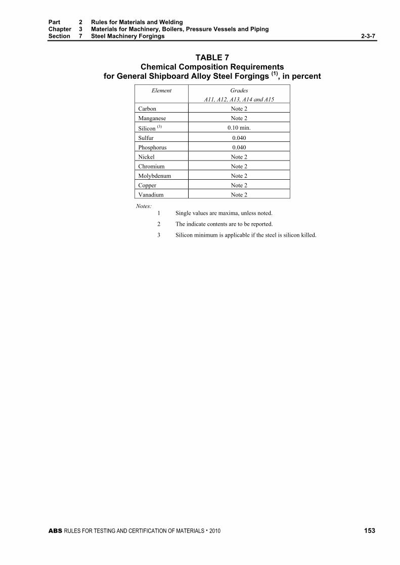
Part 2 Rules for Materials and Welding Chapter 3 Materials for Machinery, Boilers, Pressure Vessels and Piping Section 7 Steel Machinery Forgings 2-3-7
ABS RULES FOR TESTING AND CERTIFICATION OF MATERIALS . 2010 153
TABLE 7 Chemical Composition Requirements
for General Shipboard Alloy Steel Forgings (1), in percent Element Grades
A11, A12, A13, A14 and A15 Carbon Note 2
Manganese Note 2
Silicon (3) 0.10 min.
Sulfur 0.040 Phosphorus 0.040 Nickel Note 2 Chromium Note 2 Molybdenum Note 2 Copper Note 2 Vanadium Note 2
Notes: 1 Single values are maxima, unless noted.
2 The indicate contents are to be reported.
3 Silicon minimum is applicable if the steel is silicon killed.

Part 2 Rules for Materials and Welding Chapter 3 Materials for Machinery, Boilers, Pressure Vessels and Piping Section 7 Steel Machinery Forgings 2-3-7
154 ABS RULES FOR TESTING AND CERTIFICATION OF MATERIALS . 2010
TABLE 8 Tensile Property Requirements
for General Shipboard Alloy Steel Forgings (1) (2008) Longitudinal Tangential
Elongation (3),in percent
Elongation (3), in percent
Gauge Length Gauge Length
Grade Size, in mm (in)
Tensile Strength, in N/mm2
(kgf/mm2, ksi)
Yield Strength (2), in N/mm2
(kgf/mm2, ksi)
4d 5d
RA, in
percent
4d 5d
RA, in
percent
≤ 180 (7) 655 (67, 95) 485 (49, 70) 20 18 50 18 16 40
> 180 (7) ≤ 255 (10)
620 (63, 90) 450 (46, 65) 20 18 50 18 16 40 A11
> 255 (10) ≤ 510 (20)
620 (63, 90) 450 (46, 65) 18 16 48 16 15 40
≤ 180 (7) 725 (74, 105) 550 (56, 80) 20 18 50 18 16 40
> 180 (7) ≤ 255 (10)
690 (70, 100) 515 (53, 75) 19 17 50 17 16 40
A12
> 255 (10) ≤ 510 (20)
690 (70, 100) 515 (53, 75) 18 16 48 16 15 40
≤ 100 (4) 860 (88, 125) 725 (74, 105) 16 15 50 14 13 40
> 100 (4) ≤ 180 (7)
795 (81, 115) 655 (67, 95) 16 15 45 14 13 35
> 180 (7) ≤ 255 (10)
760 (77, 110) 585 (60, 85) 16 15 45 14 13 35
A13
> 255 (10) ≤ 510 (20)
760 (77, 110) 585 (60, 85) 14 13 40 12 11 30
≤ 100 (4) 1000 (102, 145) 825 (84, 120) 15 14 45 13 12 35
> 100 (4) ≤ 180 (7)
965 (98, 140) 795 (81, 115) 14 13 40 12 11 30
> 180 (7) ≤ 255 (10)
930 (95, 135) 760 (77, 110) 13 12 40 12 11 30
A14
> 255 (10) ≤ 510 (20)
930 (95, 135) 760 (77, 110) 12 11 38 11 10 30
≤ 100 (4) 1170 (120, 170) 965 (98, 140) 13 12 40 11 10 30
> 100 (4) ≤ 180 (7)
1140 (116, 165) 930 (95, 135) 12 11 35 11 10 30
> 180 (7) ≤ 255 (10)
1105 (112, 160) 895 (91, 130) 11 10 35 10 9 28
A15
> 255 (10) ≤ 510 (20)
1105 (112, 160) 895 (91, 130) 11 10 35 10 9 28
Notes: 1 All tensile property requirements are minima, unless indicated.
2 Yield strength is determined by the 0.2% offset method.
3 Elongation gauge length is 50 mm (2 in.); see 2-3-1/Figure 2.
RA = Reduction of Area

ABS RULES FOR TESTING AND CERTIFICATION OF MATERIALS . 2010 155
P A R T S e c t i o n 8 : H o t - r o l l e d S t e e l B a r s f o r M a c h i n e r y
2 C H A P T E R 3 Materials for Machinery, Boilers, Pressure
Vessels, and Piping
S E C T I O N 8 Hot-rolled Steel Bars for Machinery
1 Hot-rolled Steel Bars Hot-rolled steel bars up to and including 305 mm (12 in.) diameter, presented for inspection after special approval for each specific application, are to be made by one or more of the following processes: open-hearth, basic-oxygen, electric-furnace or such other process as may be approved. Hot-rolled bars used in lieu of carbon-steel forgings (see Section 2-3-7) are to be fully killed, heat treated in accordance with 2-3-7/1.5, and the cross-sectional area of the unmachined finished bar is not to exceed one-sixth of the cross-sectional area of the ingot. In addition, hot-rolled bars used in lieu of forgings for tail shafts are to meet the nondestructive examination requirements of 2-3-7/1.13.1. The tensile properties are to meet the requirements of 2-3-7/1.7 for the proposed application.
3 Number of Tests Four tension tests are to be taken from each lot of material exceeding 907 kg (2000 lb) in weight. When the weight of a lot is 907 kg (2000 lb) or less, two tension tests may be taken. In any case, only one tension test will be required from any one bar. A lot is to consist of bars from the same heat; if the bars are heat-treated, then a lot is to consist of bars from the same heat which have been heat-treated in the same furnace charge. If the bars in a lot differ 9.5 mm (0.375 in.) or more in diameter, the test specimens taken are to be representative of the greatest and least diameter bar.

156 ABS RULES FOR TESTING AND CERTIFICATION OF MATERIALS . 2010
P A R T Section 9: Steel Castings for Machinery, Boilers and Pressure Vessels
2 C H A P T E R 3 Materials for Machinery, Boilers, Pressure
Vessels, and Piping
S E C T I O N 9 Steel Castings for Machinery, Boilers and Pressure Vessels
1 General
1.1 Process of Manufacture (2005) The following requirements cover carbon-steel castings intended to be used in machinery, boiler and pressure-vessel construction, such as crankshafts, turbine casings and bedplates. For other applications, additional requirements may be necessary, especially when the castings are intended for service at low temperatures. Castings which comply with national or proprietary specifications may also be accepted, provided such specifications give reasonable equivalence to these requirements. None of the above preclude the use of alloy steels in accordance with the permissibility expressed in 2-3-1/1. The steel is to be manufactured by a process approved by the Bureau.
Castings are to be made by a manufacturer approved by the Bureau. The Surveyor is permitted at any time to monitor important aspects of casting production, including mold preparation and chaplet positioning; pouring times and temperatures; mold breakout; repairs; heat treatment and inspection.
Thermal cutting, scarfing or arc-air gouging to remove surplus metal is to be undertaken in accordance with recognized good practice and is to be carried out before the final heat treatment. Preheating is to be employed when necessitated by the chemical composition and/or thickness of the castings. If necessary, the affected areas are to be either machined or ground smooth.
When two or more castings are joined by welding to form a composite component, the proposed welding procedure is to be submitted for approval and welding is to be carried out to the satisfaction of the attending Surveyor.
Sulfur and phosphorous contents are to be less than 0.040% and silicon less than 0.60%.
For welded construction, the maximum carbon content is to be 0.23%.
1.3 ASTM Designations (2005) The various Grades are in substantial agreement with ASTM, as follows and, in addition, the requirements of this Section apply:
ABS Grade ASTM Designation 1 A27, Grade 60–30 2 A27, Grade 70–36 3 A216, Grade WCA 4 A216, Grade WCB

Part 2 Rules for Materials and Welding Chapter 3 Materials for Machinery, Boilers, Pressure Vessels and Piping Section 9 Steel Castings for Machinery, Boilers and Pressure Vessels 2-3-9
ABS RULES FOR TESTING AND CERTIFICATION OF MATERIALS . 2010 157
3 Marking and Retests
3.1 Marking (2005) The manufacturer is to adopt a system of identification which will enable all finished castings to be traced to the original cast and the Surveyor is to be given full facilities for tracing the castings when required.
The manufacturer’s name or identification mark and pattern number is to be cast on all castings, except those of such small size as to make this type of marking impracticable. The Bureau markings, indicating satisfactory compliance with the Rule requirements, and as furnished by the Surveyor is to be stamped on all castings accepted in such location as to be discernible after machining and installation. Grade 1, 2, 3 and 4 castings are to be stamped AB/1, AB/2, AB/3 and AB/4, respectively. In addition, identification numbers of the heats used for pouring the castings are to be stamped on all castings individually weighing 227 kg (500 lb) or more.
3.3 Retests (2005) If the results of the physical tests for any casting or any lot of castings do not conform to the requirements specified, the manufacturer may reheat-treat castings or lots of castings that have failed to meet test requirements. Two additional test samples representative of the casting or casting batch may be taken. If satisfactory results are obtained from both of the additional tests, the casting or batch of castings is acceptable. If one or both retests fail, the casting or batch of castings is to be rejected.
5 Heat Treatment (2005) Except in cases specifically approved otherwise, all castings are to be either fully annealed, normalized or normalized and tempered in a furnace of ample proportions to bring the whole casting to uniform temperature above the transformation range on the annealing or normalizing cycle. The furnaces are to be maintained and have adequate means for control and recording temperature. Castings are to be held soaking at the proper temperature for at least a length of time equivalent to one hour per 25.5 mm (1 in.) of thickness of the heaviest member. No annealed casting is to be removed from the furnace until the temperature of the entire furnace charge has fallen to or below a temperature of 455°C (850°F). A sufficient number of thermocouples are to be connected to the furnace charge to measure and record that its temperature is adequately uniform, unless the temperature uniformity of the furnace can be verified at regular intervals. Tempering is to be carried out at a temperature of not less than 550°C (1022°F).
Local heating or cooling and bending and straightening of annealed castings are not permitted, except with the express sanction of the Surveyor.
The foundry is to maintain records of heat treatment, identifying the furnace used, furnace charge, date, temperature and time at temperature, together with the number and location of thermocouples. The records are to be available to the Surveyor upon request.
7 Tensile Properties (2008) Steel castings are to conform to the following requirements as to tensile properties.
Elongation Min., %
Gauge Length
ABS
Grade
Tensile Strength,
Min., N/mm2 (kgf/mm2, psi)
Yield Point/ Yield Strength, Min., N/mm2
(kgf/mm2, psi)
4d 5d
Reduction of Area
Min%
1 415 (42, 60000) 205 (21.0, 30000) 24 22 35 2 485 (49, 70000) 250 (25.5, 36000) 22 20 30 3 415 (42, 60000) 205 (21.0, 30000) 24 22 35 4 485 (49, 70000) 250 (25.5, 36000) 22 20 35

Part 2 Rules for Materials and Welding Chapter 3 Materials for Machinery, Boilers, Pressure Vessels and Piping Section 9 Steel Castings for Machinery, Boilers and Pressure Vessels 2-3-9
158 ABS RULES FOR TESTING AND CERTIFICATION OF MATERIALS . 2010
9 Application
9.1 General and High-temperature Applications Any of the above grades may be used for miscellaneous applications. Grade 3 or Grade 4 castings are to be used for boiler mountings, valves, fittings and for pressure parts of boilers and other pressure vessels where the temperature does not exceed 427°C (800°F). See 4-6-2/3.1.2 of the ABS Rules for Building and Classing Steel Vessels.
9.3 Propeller and Forging Applications Any of the above grades may be used for propellers and for castings which have been approved to take the place of forgings.
9.5 Alloy Steels or Special Carbon Steels When alloy steels or carbon steels differing from the requirements of 2-3-9/7 are proposed for any purpose, the purchaser’s specification shall be submitted for approval in connection with the approval of the design for which the material is proposed. Specifications such as ASTM A356 or A217 Grades WC1, WC6, or WC9, or other steels suitable for the intended service will be considered.
11 Test Specimens
11.1 Material Coupons (2005) Test material, sufficient for the required number of tests and for possible retest purposes, is to be provided for each casting. The physical properties are to be determined from test specimens prepared from coupons which, except as specified in 2-3-9/11.3, are to be cast integral with the casting to be inspected. When this is impracticable, the coupons may be cast with and gated to the casting and are to have a thickness of not less than 30 mm (1.2 in.). In either case, these coupons are not to be detached until the heat treatment of the castings has been completed, nor until the coupons have been stamped by the Surveyor for identification. Where the material identification system of the manufacturer is found acceptable to the Bureau and is maintained in that condition through initial and periodical verification by the Bureau, it may be considered in lieu of stamping by the Surveyor before detachment.
Where the casting finished mass exceeds 10,000 kg (22,000 lb) or is of complex design, two test samples are to be provided. Where large castings are made from two or more casts which are not from the same pour, two or more test samples are to be provided, corresponding to the number of casts involved. The samples are to be integrally cast at locations as widely separated as possible.
11.3 Separately Cast Coupons In the case of small castings having an estimated weight of less than 907 kg (2000 lb), each of the coupons may be cast separately, provided the Surveyor is furnished an affidavit by the manufacturer stating that the separately cast coupons were cast from the same heat as the castings represented and that they were heat-treated with the castings.
13 Number of Tests
13.1 Machinery Castings (2005) At least one tension test is to be made from each heat in each heat-treatment charge, except where two or more samples are required as indicated in 2-3-9/11.1. If the manufacturer’s quality-control procedure includes satisfactory automatic chart recording of temperature and time, then one tension test from each heat for castings subject to the same heat-treating procedure may be allowed at the discretion of the attending Surveyor.
13.3 Steel Propeller Castings One tension test is to be made from each blade of a built-up propeller, and for solid propellers there is to be one tension test from each of two opposite blades when the propeller is over 2130 mm (7 ft) in diameter and one tension test from one of the blades when the diameter of the propeller is 2130 mm (7 ft) or smaller.

Part 2 Rules for Materials and Welding Chapter 3 Materials for Machinery, Boilers, Pressure Vessels and Piping Section 9 Steel Castings for Machinery, Boilers and Pressure Vessels 2-3-9
ABS RULES FOR TESTING AND CERTIFICATION OF MATERIALS . 2010 159
15 Inspection and Repair
15.1 General (2008) All castings are to be examined by the Surveyor after final heat treatment and thorough cleaning to ensure that the castings are free from defects. Where applicable internal surfaces are to be inspected, surfaces are not to be hammered or peened or treated in any way which may obscure defects.
In the event of a casting proving to be defective during subsequent machining or testing, it is to be rejected, notwithstanding any previous certification.
The manufacturer is to verify that all dimensions meet the specified requirements. The Surveyor is to spot check key dimensions to confirm the manufacturer’s recorded dimensions.
When required by the relevant construction Rules, castings are to be pressure tested before final acceptance. The tests are to be carried out in the presence and to the satisfaction of the attending Surveyor.
15.3 Minor Defects (2006) Defects are to be considered minor when the cavity prepared for welding has a depth not greater than 20% of the actual wall thickness, but in no case greater than 25 mm (1 in.), and has no lineal dimension greater than four times the wall thickness nor greater than 150 mm (6 in.). Shallow grooves or depressions resulting from the removal of defects may be accepted, provided that they will cause no appreciable reduction in the strength of the casting. The resulting grooves or depressions are to be subsequently ground smooth and complete elimination of the defective material is to be verified by MT or PT. Repairs of minor defects where welding is required are to be treated as weld repairs and repaired in accordance with an approved procedure. Minor defects in critical locations are to be treated as, and repaired in the same manner as, major defects.
15.5 Major Defects Defects other than minor defects with dimensions greater than those given in 2-3-9/15.3 above, may, with the Surveyor’s approval, be repaired by welding using an approved procedure.
15.7 Welded Repair (2010) After it has been agreed that a casting can be repaired by welding, full details of the extent and location of the repair, the proposed welding procedure, heat treatment and subsequent inspection procedures are to be submitted for approval.
Before undertaking the repair welding of castings, the manufacturer is to prove to the satisfaction of the Surveyor that the welders or welding operators are duly qualified for the work intended.
Removal of defects and weld repair are to be carried out in accordance with a recognized standard. See Part 2, Appendix 6. The defects are to be removed to sound metal, and before welding, the excavation is to be investigated by suitable approved, nondestructive examination methods to ensure that the defect has been removed. In the case of repair of major defects, welding is not permitted on unheat-treated castings. Corrective welding is to be associated with the use of preheat.
15.9 Postweld-repair Heat Treatment (2005) All welded repairs of defects are to be given a suitable postweld heat treatment, as indicated in 2-3-9/5, or subject to the prior agreement of the materials department consideration may be given to the acceptance of a local stress relieving heat treatment at a temperature of not less than 550°C (1022°F). The heat treatment employed will be dependant on the chemical composition of the casting, the casting and dimensions, and the position of the repairs.
On completion of heat treatment, the weld repairs and adjacent material are to be ground smooth and examined by magnetic particle or liquid penetrant testing. Supplementary examination by ultrasonics or radiography may also be required, depending on the dimensions and nature of the original defect. Satisfactory results are to be obtained from all forms of nondestructive testing used.
The manufacturer is to maintain full records detailing the extent and location of minor and major repairs made to each casting and details of weld procedures and heat treatments applied. These records are to be available to the Surveyor and copies provided on request.

Part 2 Rules for Materials and Welding Chapter 3 Materials for Machinery, Boilers, Pressure Vessels and Piping Section 9 Steel Castings for Machinery, Boilers and Pressure Vessels 2-3-9
160 ABS RULES FOR TESTING AND CERTIFICATION OF MATERIALS . 2010
15.11 Crankshaft Castings (2005) The foregoing provisions may not apply in their entirety to the repair of crankshaft castings. In the case of repair of crankshaft castings, the applicable procedures and extent of repairs will be specially considered. All castings for crankshafts are to be suitably preheated prior to welding.
17 Castings for Ice-strengthened Propellers Castings for ice-strengthened propellers are to comply with 2-3-14/5.
19 Nondestructive Testing (2005) When required by the relevant construction Rules or by the approved procedure for welded components, appropriate nondestructive testing is also to be carried out before acceptance and the results are to be reported by the manufacturer. The extent of testing and acceptance criteria are to be agreed with the Bureau. Part 2, Appendix 6 is regarded as an example of an acceptable standard. Additional NDE is to be considered at chaplet locations and areas of expected defects.
21 Certification (2005) The manufacturer is to provide the required type of inspection certificate giving the following particulars for each casting or batch of castings which has been accepted:
i) Purchaser’s name and order number
ii) Description of forgings and steel quality
iii) Identification number
iv) Steelmaking process, cast number and chemical analysis of ladle sample
v) Results of mechanical tests
vi) Results of nondestructive tests, where applicable
vii) Details of heat treatment, including temperature and holding times.
viii) Where applicable, test pressure.
ix) Specification

ABS RULES FOR TESTING AND CERTIFICATION OF MATERIALS . 2010 161
P A R T S e c t i o n 1 0 : D u c t i l e ( N o d u l a r ) I r o n C a s t i n g s
2 C H A P T E R 3 Materials for Machinery, Boilers, Pressure
Vessels, and Piping
S E C T I O N 10 Ductile (Nodular) Iron Castings (2006)
1 Scope
1.1 Important spheroidal or nodular graphite iron castings, as defined in the relevant construction Rules, are to be manufactured and tested in accordance with the requirements of this Section.
1.3 These requirements are applicable only to castings where the design and acceptance tests are related to mechanical properties at ambient temperature. For other applications additional requirements may be necessary, especially when the castings are intended for service at low or elevated temperatures.
1.5 Alternatively, castings which comply with national or proprietary specifications may be accepted provided such specifications give reasonable equivalence to these requirements or otherwise are specially approved or required by the Bureau.
1.7 Where small castings are produced in large quantities, the manufacturer may employ alternative procedures for testing and inspection subject to the approval of the Bureau.
3 Manufacture
3.1 (2008) All important castings (i.e., castings that are required to be certified per 4-2-1/Table 1) are to be made at foundries where the manufacturer has demonstrated to the satisfaction of the Bureau that the necessary manufacturing and testing facilities are available and are supervised by qualified personnel.
3.3 Suitable mechanical methods are to be employed for the removal of surplus material from castings. Thermal cutting processes are not acceptable, except as a preliminary operation to mechanical methods.
3.5 Where castings of the same type are regularly produced in quantity, the manufacturer is to make tests necessary to prove the quality of the prototype castings and is also to make periodical examinations to verify the continued efficiency of the manufacturing technique. The Surveyor is to be given the opportunity to witness these tests.

Part 2 Rules for Materials and Welding Chapter 3 Materials for Machinery, Boilers, Pressure Vessels and Piping Section 10 Ductile (Nodular) Iron Castings 2-3-10
162 ABS RULES FOR TESTING AND CERTIFICATION OF MATERIALS . 2010
5 Quality of Casting Castings are to be free from surface or internal defects which would prove detrimental to their proper application in service. The surface finish is to be in accordance with good practice and any specific requirements of the approved design.
7 Chemical Composition The chemical composition of the iron used is left to the discretion of the manufacturer, who is to ensure that it is suitable to obtain the mechanical properties specified for the castings. The chemical composition of the ladle samples is to be reported to the Bureau.
9 Heat Treatment
9.1 Except as required by 2-3-10/9.3, castings may be supplied in either the as cast or heat-treated condition.
9.3 For applications such as high temperature service or where dimensional stability is important, it may be required that castings be given a suitable tempering or stress relieving heat treatment. This is to be carried out after any refining heat treatment and before machining The materials in 2-3-10/Table 2 are to undergo a ferritizing heat treatment.
9.5 Where it is proposed to locally harden the surfaces of a casting, full details of the proposed procedure and specification are to be submitted for approval.
11 Mechanical Tests
11.1 Test material, sufficient for the required tests and for possible re-test purposes, is to be provided for each casting or batch of castings.
11.3 The test samples are generally to be one of the standard types detailed in 2-3-10/Figures 1, 2 and 3 with a thickness of 25 mm (1.0 in.). Test samples of other dimensions to 2-3-10/Figures 1, 2 and 3 may, however, be specially required for some components.

Part 2 Rules for Materials and Welding Chapter 3 Materials for Machinery, Boilers, Pressure Vessels and Piping Section 10 Ductile (Nodular) Iron Castings 2-3-10
ABS RULES FOR TESTING AND CERTIFICATION OF MATERIALS . 2010 163
FIGURE 1 Type A Test Samples (U-type) v z
y
x
u
Rs
3° taper
Dimensions – mm (in.) Standard Sample Alternative Samples when Specially Required u 25 (1.0) 12 (0.5) 50 (2.0) 75 (3.0) v 55 (2.2) 40 (1.6) 90 (3.5) 125 (5.0) x 40 (1.6) 30 (1.2) 60 (2.4) 65 (2.6) y 100 (4.0) 80 (3.2) 150 (6.0) 165 (6.5) z To suit testing machine
Rs Approximately 5 mm (0.20 in.)
FIGURE 2 Type B Test Samples (Double U-type)
v z
y
x
u
Rs
3° taper
uu
Dimensions – mm (in.) Standard Sample u 25 (1.0) v 90 (3.5) x 40 (1.6) y 100 (4.0) z To suit testing machine
Rs Approximately 5 mm (0.20 in.)

Part 2 Rules for Materials and Welding Chapter 3 Materials for Machinery, Boilers, Pressure Vessels and Piping Section 10 Ductile (Nodular) Iron Castings 2-3-10
164 ABS RULES FOR TESTING AND CERTIFICATION OF MATERIALS . 2010
FIGURE 3 Type C Test Samples (Y-type) v z
y
x
u
Dimensions – mm (in.) Standard Sample Alternative Samples when Specially Required u 25 (1.0) 12 (0.5) 50 (2.0) 75 (3.0) v 55 (2.2) 40 (1.6) 100 (4.0) 125 (5.0) x 40 (1.6) 25 (1.0) 50 (2.4) 65 (2.6) y 140 (5.5) 135 (5.5) 150 (6.0) 175 (7.0) z To suit testing machine
Min. thickness of mold surrounding test sample
40 (1.6) 40 (1.6) 80 (3.2) 80 (3.2)
11.5 At least one test sample is to be provided for each casting and, unless otherwise required, may be either gated to the casting or separately cast. Alternatively, test material of other suitable dimensions may be provided integral with the casting.
11.7 For large castings where more than one ladle of treated metal is used, additional test samples are to be provided so as to be representative of each ladle used.
11.9 As an alternative to 2-3-10/11.3, a batch testing procedure may be adopted for castings with a fettled mass of 1,000 kg (2,200 lb) or less. All castings in a batch are to be of similar type and dimensions, and cast from the same ladle of treated metal. One separately cast test sample is to be provided for each multiple of 2,000 kg (4,400 lb) of fettled castings in the batch.
11.11 Where separately cast test samples are used, they are to be cast in molds made from the same type of material as used for the castings and are to be taken towards the end of pouring of the castings. The samples are not to be stripped from the molds until the temperature is below 500°C (930°F).
11.13 All test samples are to be suitably marked to identify them with the castings which they represent.
11.15 Where castings are supplied in the heat treated condition, the test samples are to be heat treated together with the castings which they represent.

Part 2 Rules for Materials and Welding Chapter 3 Materials for Machinery, Boilers, Pressure Vessels and Piping Section 10 Ductile (Nodular) Iron Castings 2-3-10
ABS RULES FOR TESTING AND CERTIFICATION OF MATERIALS . 2010 165
11.17 One tensile specimen is to be prepared from each test sample and is to be machined to the dimensions given in 2-3-1/Figure 2. Note that for nodular cast iron with an elongation less than 10%, the radius R ≥ 20 mm (0.8 in.).
11.19 All tensile tests are to be carried out using test procedures in accordance with Section 2-3-1. Unless otherwise agreed, all tests are to be carried out in the presence of the Surveyor.
11.21 Impact tests may additionally be required. In such cases a set of three specimens of an agreed type is to be prepared from each sample. Where Charpy V-notch test specimens are used, the dimensions and testing procedures are to be in accordance with 2-1-1/Figure 3.
13 Mechanical Properties
13.1 2-3-10/Tables 1 and 2 give the minimum requirement for 0.2% proof stress and elongation corresponding to different strength levels. Typical Brinell hardness values are also given in 2-3-10/Table 1 and are intended for information purposes only.
13.3 Castings may be supplied to any specified minimum tensile strength selected within the general limits detailed in 2-3-10/Table 1, and any additional requirements of the relevant construction Rules.
13.5 Unless otherwise agreed, only the tensile strength and elongation need to be determined. The results of all tensile tests are to comply with the appropriate requirements of 2-3-10/Table 1.
13.7 When the tensile test fails to meet the requirements, two further tests may be made from the same piece. If both these additional tests are satisfactory, the item and/or batch (as applicable) is acceptable. If one or both of these tests fail, the item and/or batch is to be rejected.
The additional tests detailed above are to be taken preferably from material taken adjacent to the original tests, but alternatively from another test position or sample representative of the item/batch.
TABLE 1 Mechanical Properties for Spheroidal or Nodular Cast Iron
Specified minimum Tensile strength,
N/mm2 (ksi)
0.2% proof stress, N/mm2 (ksi)
Elongation on 5.65 oS (%) min
Typical hardness (Brinell)
Typical structure of matrix
370 (54) 230 (33) 17 120-180 Ferrite 400 (58) 250 (36) 12 140-200 Ferrite 500 (73) 320 (46) 7 170-240 Ferrite/Pearlite 600 (87) 370 (54) 3 190-270 Ferrite/Pearlite 700 (102) 420 (61) 2 230-300 Pearlite 800 (116) 480 (70) 2 250-350 Pearlite or
tempered structure

Part 2 Rules for Materials and Welding Chapter 3 Materials for Machinery, Boilers, Pressure Vessels and Piping Section 10 Ductile (Nodular) Iron Castings 2-3-10
166 ABS RULES FOR TESTING AND CERTIFICATION OF MATERIALS . 2010
TABLE 2 Mechanical Properties for Spheroidal or Nodular Cast Iron
with Additional Charpy Requirements
Impact energy test min values (3) Specified minimum Tensile strength,
N/mm2 (ksi)
0.2% proof stress, N/mm2 (ksi)
Elongation on 5.65 oS (%) min
Typical hardness (Brinell) Test temp. Ave Joules
Typical structure of
matrix 350 (51) 220 (32) 22 (2) 110-170 +20 17 (14) Ferrite 400 (58) 250 (36) 18 (2) 140-200 +20 14 (11) Ferrite
Notes for tables 1 and 2: 1 Intermediate values for mechanical properties may be obtained by interpolation
2 In the case of integrally cast samples, the elongation may be 2 percentage points less.
3 The average value measured on three Charpy V-notch specimens. One result may be below the average value but not less than the minimum shown in parentheses.
15 Inspection
15.1 All castings are to be cleaned and adequately prepared for examination. The surfaces are not to be hammered, peened or treated in any way which may obscure defects.
15.3 All castings are to be visually examined by the Surveyor including, where applicable, the examination of internal surfaces. Unless otherwise agreed, the verification of dimensions is the responsibility of the manufacturer
15.5 Supplementary examination of castings by suitable nondestructive test procedures is generally not required unless otherwise stated on the approved plan or in circumstances where there is reason to suspect the soundness of the casting.
15.7 When required by the relevant construction Rules, castings are to be pressure tested before final acceptance.
15.9 In the event of any casting proving defective during subsequent machining or testing is to be rejected notwithstanding any previous certification.
15.11 Cast crankshafts are to be subjected to a magnetic particle inspection. Crack like indications are not allowed.
17 Metallographic Examination
17.1 For crankshafts, a metallograpic examination is to be carried out.
17.3 When required, a representative sample from each ladle of treated metal is to be prepared for metallograpghic examination. These samples may be taken from the tensile test specimens but alternative arrangements for the provisions of the samples may be adopted provided that they are taken from the ladle towards the end of the casting period.
Part 2 Rules for Materials and Welding Chapter 3 Materials for Machinery, Boilers, Pressure Vessels and Piping Section 10 Ductile (Nodular) Iron Castings 2-3-10
ABS RULES FOR TESTING AND CERTIFICATION OF MATERIALS . 2010 167
17.5 Examination of the samples is to show that at least 90% of the graphite is in a dispersed spheroidal or nodular form. Details of typical matrix structures are given in 2-3-10/Table 1 and are intended for information purposes only.
19 Rectification of Defective Castings
19.1 At the discretion of the Surveyor, small surface blemishes may be removed by local grinding.
19.3 Subject to approval, castings containing local porosity may be rectified by impregnation with suitable plastic filler.
19.5 Repairs by welding are generally not permitted.
21 Identification of Castings
21.1 The manufacturer is to adopt a system of identification, which will enable all finished castings to be traced to the original ladle of treated metal and the Surveyor is to be given full facilities for tracing the castings when required.
21.3 Before acceptance, all castings, which have been tested and inspected with satisfactory results are to be clearly marked by the manufacturer with the following details:
i) Grade of cast iron
ii) Identification number or other marking enabling the full history of the casting to be traced.
iii) Manufacturer’s name or trademark.
iv) Date of final inspection.
v) ABS office, initials or symbol.
vi) Personal stamp of Surveyor responsible for inspection
vii) Test pressure, if applicable
21.5 Where small castings are manufactured in large numbers, modified arrangements for identification may be specially agreed with the Surveyor.

Part 2 Rules for Materials and Welding Chapter 3 Materials for Machinery, Boilers, Pressure Vessels and Piping Section 10 Ductile (Nodular) Iron Castings 2-3-10
168 ABS RULES FOR TESTING AND CERTIFICATION OF MATERIALS . 2010
23 Certification
23.1 The manufacturer is to provide the Surveyor with a test certificate or shipping statement giving the following particulars for each casing or batch of castings which has been accepted:
i) Purchaser’s name and order number
ii) Description of castings and quality of cast iron
iii) Identification number
iv) Results of mechanical tests
v) Where applicable, general details of heat treatment
vi) Where specifically required, the chemical analysis of the ladle samples
vii) Where applicable, test pressure

ABS RULES FOR TESTING AND CERTIFICATION OF MATERIALS . 2010 169
P A R T S e c t i o n 1 1 : G r a y - i r o n C a s t i n g s
2 C H A P T E R 3 Materials for Machinery, Boilers, Pressure
Vessels, and Piping
S E C T I O N 11 Gray-iron Castings (2006)
1 Scope
1.1 Gray iron castings, as defined in the relevant construction rules, are to be manufactured and tested in accordance with the requirements of this Section.
1.3 Alternatively, castings which comply with national or proprietary specifications may be accepted, provided such specifications give reasonable equivalence to these requirements or otherwise are specially approved or required by the Bureau.
1.5 Where small castings are produced in large quantities, the manufacturer may adopt alternative procedures for testing and inspection subject to the approval of the Bureau.
3 Process of Manufacture
3.1 (2008) Gray iron castings are to be made at foundries where the manufacturer has demonstrated to the satisfaction of the Bureau that the necessary manufacturing and testing facilities are available and are supervised by qualified personnel.
3.3 Suitable mechanical methods are to be employed for the removal of surplus material from castings. Thermal cutting processes are not acceptable, except as a preliminary operation to mechanical methods.
3.5 Where castings of the same type are regularly produced in quantity, the manufacturer is to carry out tests necessary to prove the quality of the prototype castings and is also to make periodical examinations to verify the continued efficiency of the manufacturing technique. The Surveyor is to be given the opportunity to witness these tests.
5 Quality of Castings Castings are to be free from surface or internal defects, which would prove detrimental to their proper application in service. The surface finish is to be in accordance with good practice and any specific requirements of the approved design.
Part 2 Rules for Materials and Welding Chapter 3 Materials for Machinery, Boilers, Pressure Vessels and Piping Section 11 Gray-iron Castings 2-3-11
170 ABS RULES FOR TESTING AND CERTIFICATION OF MATERIALS . 2010
7 Chemical Composition The chemical composition of the iron used is left to the discretion of the manufacturer, who is to ensure that it is suitable to obtain mechanical properties specified for the castings. The composition of ladle sample is to be reported to the Bureau.
9 Heat Treatment
9.1 Except as required for 2-3-11/9.3, castings may be supplied in either the cast or heat treated condition.
9.3 For applications such as high temperature service or when dimensional stability is important, castings may require to be given a suitable tempering or stress relieving heat treatment.
11 Mechanical Tests
11.1 Test material sufficient for the required tests and for possible re-tests is to be provided for each casting or batch of castings.
11.3 Separately cast test samples are to be used unless otherwise agreed between the manufacturer and purchaser, and are to be in the form of round bars 30 mm (1.2 in.) in diameter and of a suitable length. They are to be of cast iron from the same ladle as the castings in molds of the same type of material as the molds for the castings and are not to be stripped from the molds until the metal temperature is below 500°C (930°F). When two or more test samples are cast simultaneously in a single mold, the bars are to be at least 50 mm (2.0 in.) apart.
11.5 Integrally cast samples may be used when a casting is more than 20 mm (0.8 in.) thick and its mass exceeds 200 kg (440 lb), subject to agreement between the manufacturer and the purchaser. The type and location of the sample are to be selected to provide approximately the same cooling conditions as for the casting it represents and also subject to agreement.
11.7 With the exception of 2-3-11/11.13, at least one test sample is to be cast with each batch.
11.9 With the exception of 2-3-11/11.11, a batch consists of the castings poured from a single ladle of metal, provided that they are all of similar type and dimensions. A batch should not normally exceed 2,000 kg (4,400 lbs) of fettled castings and a single casting will constitute a batch if its mass is 2,000 kg (4,400 lbs) or more.
11.11 For large mass casting of the same grade, produced by continuous melting, the batch weight may be taken as the weight of casting produced in two hours of pouring. The pouring rate is not to be accelerated beyond the capacity of the caster.

Part 2 Rules for Materials and Welding Chapter 3 Materials for Machinery, Boilers, Pressure Vessels and Piping Section 11 Gray-iron Castings 2-3-11
ABS RULES FOR TESTING AND CERTIFICATION OF MATERIALS . 2010 171
11.13 If one grade of cast iron is melted in large quantities and production is monitored by systematic checking of the melting process, such as a chill testing, chemical analysis or thermal analysis, test samples may be taken at longer intervals, as agreed by the Surveyor.
11.15 All test samples are to be suitably marked to identify them with the castings which they represent.
11.17 Where castings are supplied in the heat-treated condition, the test samples are to be heat treated together with the castings which they represent. For cast-on-test samples, the sample shall not be removed from the casting until after the heat treatment.
11.19 One tensile test specimen is to be prepared from each test sample. 30 mm (1.2 in.) diameter samples are to be machined to the dimensions given in 2-3-1/Figure 3. Where test samples of other dimensions are specially required, the tensile test specimens are to be machined to agreed dimensions.
11.21 All tensile tests are to be carried out using test procedures in accordance with Section 2-3-1. Unless otherwise agreed, all tests are to be carried out in the presence of the Surveyor.
13 Mechanical Properties
13.1 Tensile Strength 13.1.1
The tensile strength is to be determined, and the results obtained from tests are to comply with the minimum value specified for the castings being supplied. The value selected for the specified minimum tensile strength is not to be less than 200 N/mm2 (29.0 ksi) but subject to any additional requirements of the relevant construction Rules. The fractured surfaces of all tensile test specimens are to be granular and gray in appearance.
13.1.2 When the tensile test fails to meet the requirements, two further tests may be made from the same piece. If both of these additional tests are satisfactory, the item and/or batch (as applicable) is acceptable. If one or both of these tests fail, the item and/or batch is to be rejected.
13.1.3 Higher Strength Castings When higher-strength cast iron is proposed for any purpose, the purchaser’s specifications are to be submitted specially for approval in connection with the approval of the design for which the material is intended.
15 Inspection
15.1 All castings are to be cleaned and adequately prepared for examination. The surfaces are not to be hammered, peened or treated in any way which may obscure defects.
15.3 All castings are to be visually examined by the Surveyor including the examination of internal surfaces where applicable. Unless otherwise agreed, the verification of dimensions is the responsibility of the manufacturer.

Part 2 Rules for Materials and Welding Chapter 3 Materials for Machinery, Boilers, Pressure Vessels and Piping Section 11 Gray-iron Castings 2-3-11
172 ABS RULES FOR TESTING AND CERTIFICATION OF MATERIALS . 2010
15.5 Supplementary examination of castings by suitable nondestructive testing procedures is generally not required unless otherwise stated on the approved plan or in circumstances where there is reason to suspect the soundness of the casting.
15.7 When required by the relevant construction Rules, castings are to be pressure tested before final acceptance.
15.9 In any event of any casting proving defective during subsequent machining or testing, it is to be rejected notwithstanding any previous certification.
17 Rectification of Defective Casting
17.1 At the discretion of the Surveyor, small surface blemishes may be removed by local grinding.
17.3 Subject to approval, castings containing local porosity may be rectified by impregnation with a suitable plastic filler.
17.5 Repairs by welding are generally not permitted. In cases where welding is proposed, full details of the proposed repair are to be submitted for review prior to commencing the repair.
19 Identification of Castings
19.1 The manufacturer is to adopt a system of identification, which will enable all finished castings to be traced to the original ladle of metal. The Surveyor is to be given full facilities for tracing the castings when required.
19.3 Before acceptance, all castings which have been tested and inspected with satisfactory results are to be clearly marked by the manufacturer with the following details:
• Grade of cast iron
• Identification number or other marking enabling the full history of the casting to be traced.
• Manufacturer’s name or trademark.
• Date of final inspection
• ABS office, initials or symbol
• Personal stamp of Surveyor responsible for inspection
• Test pressure, if applicable
19.5 Where small castings are manufactured in large numbers, modified arrangements for identification may be specially agreed with the Surveyor.

Part 2 Rules for Materials and Welding Chapter 3 Materials for Machinery, Boilers, Pressure Vessels and Piping Section 11 Gray-iron Castings 2-3-11
ABS RULES FOR TESTING AND CERTIFICATION OF MATERIALS . 2010 173
21 Certification The manufacturer is to provide the Surveyor with a test certificate or shipping statement giving the following particulars for each casting or batch of castings which has been accepted:
• Purchaser’s name and order number
• Description of castings and quality of cast iron
• Identification number
• Results of mechanical test
• Where applicable, general details of the heat treatment
• Where specifically required, the chemical analysis of ladle samples
• Where applicable, test pressures
174 ABS RULES FOR TESTING AND CERTIFICATION OF MATERIALS . 2010
P A R T S e c t i o n 1 2 : S t e e l P i p i n g
2 C H A P T E R 3 Materials for Machinery, Boilers, Pressure
Vessels, and Piping
S E C T I O N 12 Steel Piping
1 Scope (1998) The following specifications cover thirteen grades of steel pipe designated 1, 2, 3, 4, 5, 6, 7, 8, 9, 11, 12, 13 and 14.
3 General
3.1 Grades 1, 2 and 3 Grades 1, 2 and 3 cover seamless and welded steel pipe. Pipe ordered under these grades is of a nominal (average) wall thickness suitable for welding and suitable for forming operations involving coiling, bending and flanging, subject to the following limitations: Grade 1 furnace-butt-welded pipe is not intended for flanging; when seamless or electric-resistance-welded pipe is required for close-coiling or cold-bending, Grade 2 should be specified; this provision is not intended to prohibit the cold-bending of Grade 3 pipe. When pipe is required for close-coiling, this is to be specified on the order. Electric-resistance-welded Grades 2 and 3 may be furnished either non-expanded or cold-expanded, at the option of the manufacturer. When pipe is cold expanded, the amount of expansion is not to exceed 1.5% of the outside diameter pipe size.
3.3 Grades 4 and 5 Grades 4 and 5 cover seamless carbon-steel pipe for high-temperature service. Pipe ordered to these grades is of a nominal (average) wall thickness and is to be suitable for bending, flanging and similar forming operations. Grade 4 rather than Grade 5 pipe should be used for close-coiling, cold-bending or forge-welding; this provision is not intended to prohibit the cold-bending of Grade 5 pipe.
3.5 Grade 6 Grade 6 covers seamless carbon-molybdenum alloy-steel pipe for high-temperature service. Pipe ordered to this grade is of a nominal (average) wall thickness and is to be suitable for bending, flanging (vanstoning) and similar forming operations, and for fusion-welding.
3.7 Grades 7, 11, 12, 13 and 14 (1998) Grades 7, 11, 12, 13 and 14 cover seamless chromium-molybdenum alloy-steel pipe for high-temperature service. Pipe ordered to these grades is of a nominal (average) wall thickness and is to be suitable for bending, flanging (vanstoning) and similar forming operations, and for fusion-welding.
3.9 Grades 8 and 9 Grades 8 and 9 cover electric-resistance-welded steel pipe 762 mm (30 in.) and under in diameter. Pipe ordered to these grades is of a nominal (average) wall thickness and is intended for conveying liquid, gas or vapor. Only Grade 8 is adapted for flanging and bending; this provision is not intended to prohibit the cold-bending of Grade 9 pipe. The pipe may be furnished either cold-expanded or non-expanded.

Part 2 Rules for Materials and Welding Chapter 3 Materials for Machinery, Boilers, Pressure Vessels and Piping Section 12 Steel Piping 2-3-12
ABS RULES FOR TESTING AND CERTIFICATION OF MATERIALS . 2010 175
3.11 ASTM Designations (2006) The various grades are in substantial agreement with ASTM, as follows:
ABS Grade ASTM Designation 1 A53, Grade A, Furnace-welded 2 A53, Grade A Seamless or Electric-resistance-welded 3 A53, Grade B Seamless or Electric-resistance-welded 4 A106, Grade A 5 A106, Grade B 6 A335, Grade P1 7 A335, Grade P2 8 A135, Grade A 9 A135, Grade B 11 A335, Grade P11 12 A335, Grade P12 13 A335, Grade P22 14 A335, Grade P5
5 Process of Manufacture
5.1 Grades 1, 2 and 3 The steel for welded or seamless steel pipe in these Grades is to be made by one or more of the following processes: open-hearth, basic-oxygen or electric-furnace. Special consideration may be given to other processes, subject to such supplementary requirements or limits on application as are to be specially determined in each case.
5.3 Grades 4 and 5 The steel for seamless steel pipe in these Grades is to be killed steel made by one or more of the following processes: open-hearth, basic-oxygen or electric-furnace. Pipe that is 60.3 mm in outside diameter (2 in. nominal diameter) and over is to be, unless otherwise specified, furnished hot-finished. Hot-finished pipe need not be annealed. Cold-drawn pipe is to be process-annealed after the final cold-draw pass at a temperature of 650°C (1200°F) or higher.
5.5 Grades 6 and 7 The steel for seamless steel pipe in these Grades is to be made by either or both the open-hearth or electric-furnace process or other approved process. A sufficient discard is to be made from each ingot to secure freedom from injurious piping and undue segregation. Pipe that is 60.3 mm in outside diameter (2 in. nominal size) and over is to be, unless otherwise specified, furnished hot-finished, and pipe under 60.3 mm O.D. (2 in. diameter) may be furnished either hot-finished or cold-drawn. The hot-rolled or cold-drawn pipe Grades 6 and 7 as a final heat treatment, are to be stress-relief-annealed at 650°C (1200°F) to 705°C (1300°F). The steel from which Grade 7 pipe is made is to be a coarse-grained steel having a carburized austenitic grain size of 1 to 5 as determined in accordance with the Methods for Estimating the Average Grain Size of Metals (ASTM E112) and its Plate IV, by carburizing at 925°C (1700°F) for 8 hours. The specimen is to be taken from the bloom or billet.
5.7 Grades 8 and 9 The steel for electric-resistance-welded steel pipe in these Grades is to be made by one or more of the following processes: open-hearth, basic-oxygen or electric-furnace.

Part 2 Rules for Materials and Welding Chapter 3 Materials for Machinery, Boilers, Pressure Vessels and Piping Section 12 Steel Piping 2-3-12
176 ABS RULES FOR TESTING AND CERTIFICATION OF MATERIALS . 2010
5.9 Grades 11, 12, 13 and 14 (1998) The steel for seamless alloy steel pipe is to be made by the electric-furnace process or other approved process, except that Grade 12 may be made by the open-hearth process. A sufficient discard is to be made from each ingot to secure freedom from injurious piping and undue segregation. Pipe that is 60.3 mm in outside diameter (2 in. nominal diameter) and over is to be, unless otherwise specified, furnished hot-finished, and pipe under 60.3 mm O.D. (2 in. nominal diameter) may be furnished either hot-finished or cold-drawn. The steel for Grade 12 pipe is to be made by coarse-grain melting practice. Grades 11, 13 and 14 pipe are to be reheated and furnished in the full-annealed, isothermal annealed or normalized and tempered condition; if furnished in the normalized and tempered condition, or if cold drawn pipe is furnished, the temperature for tempering following normalizing or cold drawing is to be 677°C (1250°F) or higher for Grades 13 and 14, and 650°C (1200°F) or higher for Grade 11. The hot-rolled or cold-drawn Grade 12 pipe, as a final heat treatment, is to be given a stress-relieving treatment at 650°C (1200°F) to 705°C (1300°F).
7 Marking (1998) Identification markings are to be legibly stenciled, stamped, or rolled on each length of pipe, except that in the case of small-diameter pipe which is bundled, the required markings are to be placed on a tag securely attached to the bundle. The markings are to be arranged and are to include the following information:
• Name or brand of the manufacturer
• ABS Grade or ASTM Designation and Type or Grade. Heat number or manufacturer’s number by which the heat can be identified (For Grades 6, 7, 11, 12, 13and 14 pipe only)
• Test pressure or the letters NDE
• Method of forming (i.e., butt-welded, lap-welded, electric-resistance-welded or seamless hot-finished or cold-drawn)
• “XS” for extra strong or “XXS” for double-extra strong (when applicable for Grades 1, 2 and 3 pipe only)
• ABS markings by the Surveyor
9 Chemical Composition The material for pipe is to conform to the applicable requirements as to chemical composition shown in 2-3-12/Table 1.
11 Ladle Analysis (1998) For Grades 4, 5, 6, 7, 8, 9, 11, 12, 13 and 14, the manufacturer is to submit a report showing the ladle analysis of each heat of steel from which the pipe has been made and the chemical composition is to conform to the requirements specified in 2-3-12/9. In lieu of a report of the ladle analysis, a report of check analysis as provided for in 2-3-12/13 will be acceptable.
13 Check Analysis
13.1 General A check analysis may be made where so specified by the purchaser. The chemical composition thus determined is to conform to the requirements specified in 2-3-12/9. If check analyses are made, they are to be in accordance with the following requirements.
13.3 Samples Samples for check analysis are to be taken by drilling several points around each pipe selected for analysis or when taken from the billet they are to be obtained by drilling parallel to the billet axis at a point midway between the outside and center or when taken from a broken tension test specimen, they are to be taken so as to represent the entire cross section of the specimen.

Part 2 Rules for Materials and Welding Chapter 3 Materials for Machinery, Boilers, Pressure Vessels and Piping Section 12 Steel Piping 2-3-12
ABS RULES FOR TESTING AND CERTIFICATION OF MATERIALS . 2010 177
13.5 Grades 1, 2 and 3 For these grades, analyses of two pipes from each lot of 500 lengths or fraction thereof are to be made.
13.7 Grades 4 and 5 For these grades, analyses of two pipes from each lot of 400 lengths or fraction thereof, of each size and heat 60.3 mm O.D. (2 in. nominal diameter) up to, but not including 168.3 mm O.D. (6 in. nominal diameter), and from each lot of 200 lengths or fraction thereof of each size and heat 168.3 mm O.D. (6 in. nominal diameter) and over, are to be made.
13.9 Grades 6, 7, 11, 12, 13 and 14 (1998) For these grades, analyses of two pipes from each lot and heat, as specified in 2-3-12/Table 2, are to be made.
13.11 Grades 8 and 9 For these grades, analyses of two pipes from each lot of 400 lengths or fraction thereof of each size under 168.3 mm O.D. (6 in. nominal), from each lot of 200 lengths or fraction thereof of each size 168.3 mm O.D. (6 in. nominal diameter) to 508 mm (20 in.) O.D., and from each lot of 100 lengths or fraction thereof of each size over 508 mm (20 in.) O.D. to 762 mm (30 in.) O.D. are to be made. With the Surveyor’s permission, the analysis may be made of the skelp and the number is to be determined in the same manner as when taken from the finished pipe.
13.13 Retests for Grades 1, 2, 3, 4 and 5 If an analysis for these grades does not conform to the requirements specified, analyses are to be made on additional pipes of double the original number from the same lot, each of which is to conform to the requirements specified.
13.15 Retests for Grades 6, 7, 11, 12, 13 and 14 (1998) If a check or ladle analysis for these grades does not conform to the requirements specified, an analysis of each billet or pipe from the same heat or lot may be made, and all billets or pipe conforming to the requirements are to be accepted.
13.17 Retests for Grades 8 and 9 For these grades, if the analysis of either length of pipe or length of skelp does not conform to the requirements, analyses of two additional lengths from the same lot are to be made, each of which is to conform to the requirements specified.
15 Mechanical Tests Required (1998)
The type and number of mechanical tests are to be in accordance with 2-3-12/Table 3. For a description and the requirements of each test, see 2-3-12/17 through and including 2-3-12/29. For retests, see 2-3-12/33.
17 Tension Test Specimens
17.1 Grades 1, 2 and 3 For these grades, tension test specimens are to be cut longitudinally from the end of the pipe and not flattened between gauge marks. The sides of strip specimens are to be parallel between gauge marks; the width is to be 38 mm (1.5 in.) and the gauge length 50 mm (2 in.). If desired, tension test specimens may consist of a full section of pipe. When impracticable to pull a test specimen in full thickness, the tension test specimen shown in 2-3-1/Figure 2 may be used. The transverse-weld tension test specimens from electric-resistance-welded Grade 2 and Grade 3 pipe are to be taken with the weld at the center of the specimen and are to be 38 mm (1.5 in.) wide in the gauge length.
Part 2 Rules for Materials and Welding Chapter 3 Materials for Machinery, Boilers, Pressure Vessels and Piping Section 12 Steel Piping 2-3-12
178 ABS RULES FOR TESTING AND CERTIFICATION OF MATERIALS . 2010
17.3 Grades 4, 5, 6, 7, 11, 12, 13 and 14 (1998) For these grades, the tension test specimens are to be cut longitudinally, but may be cut transversely for pipe 219.1 mm in outside diameter (8 in. nominal diameter) and over.
17.3.1 Longitudinal Tension Test Specimens The longitudinal tension test may be made in full section of the pipe, up to the capacity of the testing machine. For larger sizes, tension test specimens are to consist of strips cut from the pipe; the width of these specimens is to be 38 mm (1.5 in.) and they are to have a gauge length of 50 mm (2 in.). When the pipe-wall thickness is 19.1 mm (0.75 in.) and over, the tension test specimen shown in 2-3-1/Figure 2 may be used. Longitudinal tension test specimens are not to be flattened between gauge marks. The sides of the specimens are to be parallel between gauge marks.
17.3.2 Transverse Tension Test Specimens Transverse tension test specimens may be taken from a ring cut from the pipe or from sections resulting from the flattening tests. Test specimens are to consist of strips cut transversely from the pipe; the width of the specimens is to be 38 mm (1.5 in.) and their gauge length 50 mm (2 in.). When the pipe-wall thickness is 19.1 mm (0.75 in.) and over, the tension test specimen shown in 2-3-1/Figure 2 may be used. Specimens cut from the ring section are to be flattened cold and are to be parallel between gauge marks. Specimens from Grades 6, 7, 11, 12, 13 and 14 pipes are to be flattened cold and heat-treated in the same manner as the pipe. Transverse tension test specimens may be machined off on either or both surfaces to secure uniform thickness.
17.5 Grades 8 and 9 For these grades, the tension test specimens are to be cut longitudinally from the end of the pipe, or by agreement between the manufacturer and the Surveyor, the specimens may be taken from the skelp, at a point approximately 90 degrees from the weld. The specimens are not to be flattened between the gauge marks. Transverse tension test specimens are to be taken across the weld and from the same end of the pipe as the longitudinal test specimens. The sides of each strip specimen are to be parallel between gauge marks; the width is to be 38 mm (1.5 in.) and the gauge length 50 mm (2 in.). When impracticable to pull a test specimen in full thickness, the tension test specimen shown 2-3-1/Figure 2 may be used.
19 Bend and Flattening Test Specimens
Test specimens for the bend and flattening tests are to consist of sections cut from a pipe and the specimens for flattening tests are to be smooth on the ends and free from burrs, except when made on crop ends.
21 Testing Temperature
All test specimens are to be tested at room temperature.
23 Tensile Properties
The material is to conform to the applicable requirements as to tensile properties shown in 2-3-12/Table 4.
25 Bend Test
25.1 General This test is required for Grades 1, 2, 3, 4 and 5 pipe having outside diameters of 60.3 mm (2 in. nominal diameter) and under, except that double-extra-strong pipe over 42.2 mm in outside diameter (1.25 in. nominal diameter) need not be subjected to a bend test.

Part 2 Rules for Materials and Welding Chapter 3 Materials for Machinery, Boilers, Pressure Vessels and Piping Section 12 Steel Piping 2-3-12
ABS RULES FOR TESTING AND CERTIFICATION OF MATERIALS . 2010 179
25.3 Details of Test A sufficient length of pipe is to stand being bent cold around a cylindrical mandrel without developing cracks at any portion or without opening the weld. The requirements for bending angle, mandrel diameter, and pipe diameter are tabulated below.
Pipe Grade
Bending Angle in degrees
Ratio of Mandrel Diameter to Nominal Pipe Diameter
1, 2, 3, 4, 5 90 12 1, 2, 3, 4, 5 for close-coiling 180 8
27 Flattening Test
27.1 General Flattening tests are to be made for all Grades of pipe, except Grades 1, 2 and 3 double extra strong and Grades 1, 2, 3, 4 and 5 in sizes 60.3 mm in outside diameter (2 in. nominal diameter) and under. The test is to consist of flattening cold a section of pipe between parallel plates.
27.3 Furnace-welded Pipe For Grade 1 furnace-welded pipe, the test section is not to be less than 100 mm (4 in.) in length and the weld is to be located 45 degrees from the line of direction of the applied force. The test is to be made in three steps.
27.3.1 Test Step No. 1 During the first step, which is a test for quality of the weld, no cracks or breaks on the inside, outside or end surfaces are to occur until the distance between the plates is less than three-fourths of the original outside diameter.
27.3.2 Test Step No. 2 During the second step, which is a test for ductility exclusive of the weld, the flattening is to be continued and no cracks or breaks on the inside, outside or end surfaces are to occur until the distance between the plates is less than 60% of the original outside diameter for butt-welded pipe.
27.3.3 Test Step No. 3 During the third step, which is a test for soundness, the flattening is to be continued until the test specimen breaks or the opposite walls of the pipe meet. Evidence of laminated or unsound material or of incomplete weld that is revealed during the entire flattening test is to be cause for rejection. Superficial ruptures as a result of surface imperfections are not to be cause for rejection.
27.5 Electric-resistance-welded Pipe For electric-resistance-welded pipe of Grades 2, 3, 8 and 9 the crop ends, at least 100 mm (4 in.) in length, cut from each end of each single length of pipe are to be flattened and the tests from each end are to be made alternately with the welds at 0 degrees and 90 degrees from the line of direction of force. When produced in multiple lengths, flattening tests are required from each end of each multiple length or coil with the weld at 90 degrees from the line of direction of force. In addition, tests are to be made on two intermediate rings cut from each multiple length or coil with the weld at 0 degrees from the line of direction of force. The test is to be made in three steps.
27.5.1 Test Step No. 1 During the first step, which is a test for ductility of the weld, no cracks or breaks on the inside or outside surfaces are to occur until the distance between the plates is less than two-thirds of the original outside diameter of the pipe.
Part 2 Rules for Materials and Welding Chapter 3 Materials for Machinery, Boilers, Pressure Vessels and Piping Section 12 Steel Piping 2-3-12
180 ABS RULES FOR TESTING AND CERTIFICATION OF MATERIALS . 2010
27.5.2 Test Step No. 2 During the second step, which is a test for ductility exclusive of the weld, the flattening is to be continued and no cracks or breaks on the inside or outside surfaces, elsewhere than in the weld, are to occur until the distance between the plates is less than one-third of the original outside diameter of the pipe.
27.5.3 Test Step No. 3 During the third step, which is a test for soundness, the flattening is to be continued until the test specimen breaks or the opposite walls of the pipe meet. Evidence of laminated, burned or unsound material or of an incomplete weld that is revealed during the entire flattening test is to be cause for rejection. Superficial ruptures as a result of surface imperfections are not to be cause for rejection.
27.7 Seamless Pipe (1998) For seamless pipe of Grades 2, 3, 4, 5, 6, 7, 11, 12, 13 and 14, the test section is not to be less than 63.5 mm (2.5 in.) in length. The test is to be made in two steps.
27.7.1 Test Step No. 1 During the first step, which is a test for ductility, no cracks or breaks on the inside or outside or end surfaces are to occur until the distance between the plates is less than the value of H obtained from the following equation:
H = (1 + e)t/(e + t/D)
where
H = distance between flattening plates, in mm (in.)
t = specified wall thickness of pipe, in mm (in.)
D = specified outside diameter of pipe, in mm (in.)
e = deformation per unit length, constant for a given Grade as follows.
= 0.09 for Grade 2
= 0.08 for Grades 4, 6, 7, 11, 12, 13 and 14
= 0.07 for Grades 3 and 5
27.7.2 Test Step No. 2 During the second step, which is a test for soundness, the flattening is to be continued until the specimen breaks or the opposite walls of the pipe meet. Evidence of laminated, burned or unsound material that is revealed during the entire flattening test is to be cause for rejection.
29 Hydrostatic Test
29.1 General (1998) Except when intended for structural use, such as stanchions, each length of pipe of all grades is to be hydrostatically tested at the mill in accordance with the following requirements, or when specified by the purchaser, seamless pipe is to be subjected to a nondestructive electrical test in accordance with 2-3-12/31. When each pipe is hydrostatically tested as a regular procedure during the process of manufacture, an affidavit covering this test may be accepted by the Surveyor.
29.3 Grades 1, 2 and 3 (1999) For these grades, each pipe is to withstand an internal hydrostatic pressure as shown in 2-3-12/Table 5. This does not prohibit testing at a higher pressure, but the maximum fiber stress produced by the test is not to exceed 90% of the minimum specified yield strength of the material. Welded pipe that is 60.3 mm O.D. (2 in. nominal diameter) and larger is to be jarred near one end while under test pressure. The hydrostatic pressure is to be maintained for not less than 5 seconds for all sizes of seamless and electric-welded pipe.

Part 2 Rules for Materials and Welding Chapter 3 Materials for Machinery, Boilers, Pressure Vessels and Piping Section 12 Steel Piping 2-3-12
ABS RULES FOR TESTING AND CERTIFICATION OF MATERIALS . 2010 181
29.5 Grades 4, 5, 6, 7, 11, 12, 13 and 14 (1999) For these grades, each pipe is to withstand an internal hydrostatic test pressure which will produce in the pipe wall a stress of not less than 60% of the minimum specified yield point at room temperature. This pressure is to be determined by the equation given in 2-3-12/29.9. The hydrostatic test pressure determined by the equation is to be rounded to the nearest 5 bar (5 kgf/cm2, 50 psi) for pressures below 70 bar (70 kgf/cm2, 1000 psi) and to the nearest 10 bar (10 kgf/cm2, 100 psi) for pressures 70 bar (70 kgf/cm2, 1000 psi) and above. Regardless of the pipe wall stress determined by the equation in 2-3-12/29.9, the minimum hydrostatic test pressure required to satisfy this requirement need not exceed 170 bar (170 kgf/cm2, 2500 psi) for sizes 88.9 mm O.D. (3 in. nominal diameter) and under, or 190 bar (190 kgf/cm2, 2800 psi) for all sizes over 88.9 mm O.D. (3 in. nominal diameter). This does not prohibit testing at a higher pressure, but the maximum fiber stress produced by the test is not to exceed 90% of the minimum specified yield strength of the material. The hydrostatic pressure is to be maintained for not less than 5 seconds.
29.7 Grades 8 and 9 For these grades, each pipe is to withstand an internal hydrostatic test pressure calculated from the equation given in 2-3-12/29.9. The maximum test pressure is not to exceed 172 bar (176 kgf/cm2, 2500 psi). For pipe with a wall thickness greater than 3.9 mm (0.154 in.), the pipe is to be jarred near both ends with a 1 kg (2 lb.) hammer or its equivalent while under the test pressure. The hydrostatic pressure is to be maintained for not less than 5 seconds.
29.9 Test Pressures (1999) The test pressures for applicable grades are to be determined by the following equation.
P = KSt/D
where
K = 20 (200, 2)
P = maximum hydrostatic-test pressure, in bar (kgf/cm2, psi)
t = specified thickness of pipe wall, in mm (in.)
D = specified outside diameter of pipe, in mm (in.)
S = permissible fiber stress
= 0.60 times the specified yield point, in N/mm2 (kgf/mm2 or psi), for ABS Grades 4, 5, 6, 7, 11, 12, 13 and 14
= 110 N/mm2 (11 kgf/mm2, 16000 psi) to 125 N/mm2 (12.5 kgf/mm2, 18000 psi), but in no case is the stress produced to exceed 80% of the specified yield point for ABS Grade 8
= 140 N/mm2 (14 kgf/mm2, 20000 psi) to 150 N/mm2 (15.5 kgf/mm2, 22000 psi), but in no case is the stress produced to exceed 80% of the specified yield point for ABS Grade 9
29.11 Exceptions (1999) The maximum test pressure for special service pipes, such as diesel engine high pressure fuel injection piping, will be specially considered. The manufacturer is to submit the proposed maximum test pressure along with technical justification and manufacturing control process for the piping. The justification is to include pipe fiber stress analysis and substantiating prototype test results.

Part 2 Rules for Materials and Welding Chapter 3 Materials for Machinery, Boilers, Pressure Vessels and Piping Section 12 Steel Piping 2-3-12
182 ABS RULES FOR TESTING AND CERTIFICATION OF MATERIALS . 2010
31 Nondestructive Electric Test (NDET) for Seamless Pipe (1998)
31.1 General When specified by the purchaser, seamless pipe is to be tested in accordance with ASTM E213, for Ultrasonic Examination of Metal Pipe and Tubing, ASTM E309, for Eddy-Current Examination of Steel Tubular Products Using Magnetic Saturation, ASTM E570, for Flux Leakage Examination of Ferromagnetic Steel Tubular Products, or other approved standard. It is the intent of this test to reject tubes containing defects and the Surveyor is to be satisfied that the nondestructive testing procedures are used in a satisfactory manner
31.3 Ultrasonic Calibration Standards Notches on the inside or outside surfaces may be used. The depth of the notch is not to exceed 12.5% of the specified wall thickness of the pipe or 0.1 mm (0.004 in.), whichever is greater. The width of the notch is not to exceed two times the depth.
31.5 Eddy-Current Calibration Standards In order to accommodate the various types of nondestructive electrical testing equipment and techniques in use and manufacturing practices employed, any one of the following calibration standards may be used at the option of the producer to establish a minimum sensitivity level for rejection.
31.5.1 Drilled Hole Three or four holes equally spaced about the pipe circumference and sufficiently separated longitudinally to ensure a separately distinguishable response are to be drilled radially and completely through the pipe wall, care being taken to avoid distortion of the pipe wall while drilling. The diameter of the holes is to be as follows:
Calibration Pipe Diameter in mm (inch)
Hole Diameter in mm (inch)
under 12.5 (0.5) 1 (0.039) 12.5 (0.5) to 31.8 (1.25), excl. 1.4 (0.055) 31.8 (1.25) to 50 (2.0), excl. 1.8 (0.071) 50 (2.0) to 125 (5.0), excl. 2.2 (0.087)
125 (5.0) and over 2.7 (0.106)
31.5.2 Transverse Tangential Notch Using a round file or tool with a 6.35 mm (0.25 in.) diameter, a notch is to be filed or milled tangential to the surface and transverse to the longitudinal axis of the pipe. Said notch is to have a depth not exceeding 12.5% of the nominal wall thickness of the pipe or 0.1 mm (0.004 in.), whichever is greater.
31.5.3 Longitudinal Notch A notch 0.785 mm. (0.031 in.) or less in width is to be machined in a radial plane parallel to the pipe axis on the outside surface of the tube to a depth not exceeding 12.5% of the nominal wall thickness of the pipe or 0.1 mm (0.004 in.), whichever is greater. The length of the notch is to be compatible with the testing method.
31.7 Flux Leakage Calibration Standards The depth of longitudinal notches on the inside and outside surfaces is not to exceed 12.5% of the specified wall thickness of the pipe or 0.1 mm (0.004 in.), whichever is greater. The width of the notch is not to exceed the depth, and the length of the notch is not to exceed 25.4 mm (1.0 in.). Outside and inside surface notches are to be located sufficiently apart to allow distinct identification of the signal from each notch.

Part 2 Rules for Materials and Welding Chapter 3 Materials for Machinery, Boilers, Pressure Vessels and Piping Section 12 Steel Piping 2-3-12
ABS RULES FOR TESTING AND CERTIFICATION OF MATERIALS . 2010 183
31.9 Rejection Tubing producing a signal equal to or greater than the calibration defect is to be subject to rejection.
31.11 Affidavits When each tube is subjected to an approved nondestructive electric test as a regular procedure during the process of manufacture, an affidavit covering this test may be accepted by the Surveyor.
33 Retests
33.1 General (1998) For all grades of pipe, if the results of the mechanical tests of any lot do not conform to the requirements, retests may be made on additional pipe of double the original number from the same lot, each of which is to conform to the requirements specified.
33.3 Grades 1, 2, 3, 8 and 9 For these grades, should any section fail when flattening tests are made on the crop ends of each length of welded pipe, other pieces from the length may be cut until satisfactory tests are obtained, otherwise, the length is to be rejected.
33.5 Grades 4 and 5 For these grades, should a crop end of a finished pipe fail in the flattening test, one retest may be made from the failed end. The pipe may be normalized either before or after the first test, but the pipe is to be subjected to only two normalizing treatments.
33.7 Grades 6, 7, 11, 12, 13 and 14 (1998) For these grades, should individual lengths of pipe selected to represent any lot fail to conform to the mechanical requirements, the lot may be reheat-treated and resubmitted for test, except that any individual lengths which meet the test requirements before re-treating will be accepted.
35 Pipe Testing and Inspection
35.1 Group I Piping (2008) Pipes intended for use in Group I piping systems (Class I and Class II, see 4-6-1/3, Rules for Building and Classing Steel Vessels) are to be tested, preferably at the mill, to the satisfaction of the Surveyor. The material surfaces will be examined by the Surveyor when specially requested by the purchaser. See also 4-6-7/3.5.1 of the Rules for Building and Classing Steel Vessels.
35.3 Group I and II Piping (1998) The pipes are to be reasonably straight, free from defects, and have a workmanlike finish. At a minimum, the finished pipe is to be visually inspected at the same frequency as that required for the tension test specified in 2-3-12/Table 3 for the applicable grade. Welding repair to the pipe is not to be carried out without the purchaser’s approval and is to be the Surveyor’s satisfaction.
37 Permissible Variation in Wall Thickness (1998) The permissible variations in wall thickness for all pipe are based on the ordered thickness and are to conform to that given in the applicable ASTM designation for acceptance, but the minimum thickness for all pipe is not to be less than that required by the Rules for a specific application regardless of such prior acceptance. At a minimum, the finished pipe is to be measured at the same frequency as that required for the tension test specified in 2-3-12/Table 3 for the applicable grade.

Part 2 Rules for Materials and Welding Chapter 3 Materials for Machinery, Boilers, Pressure Vessels and Piping Section 12 Steel Piping 2-3-12
184 ABS RULES FOR TESTING AND CERTIFICATION OF MATERIALS . 2010
39 Permissible Variations in Outside Diameter
39.1 Grades 1, 2, 3 For pipe of these grades 48.3 mm O.D. (1.5 in. nominal diameter) and under, the outside diameter at any point is not to vary more than 0.4 mm (0.016 in.) over nor more than 0.8 mm (0.131 in.) under the specified diameter. For pipe 60.3 mm O.D. (2 in. nominal diameter) and over, the outside diameter is not to vary more than plus or minus 1% from the specified diameter.
39.3 Grades 4, 5, 6, 7, 11, 12, 13 and 14 (1998) For these grades, variation in outside diameter from that specified is not to exceed the amount prescribed in 2-3-12/Table 6.
39.5 Grades 8 and 9 For these grades, the outside diameter is not to vary more than plus or minus 1% from the nominal diameter specified.
39.7 Inspection (1998) At a minimum, the finished pipe is to be measured at the same frequency as that required for the tension test specified in 2-3-12/Table 3 for the applicable grade.
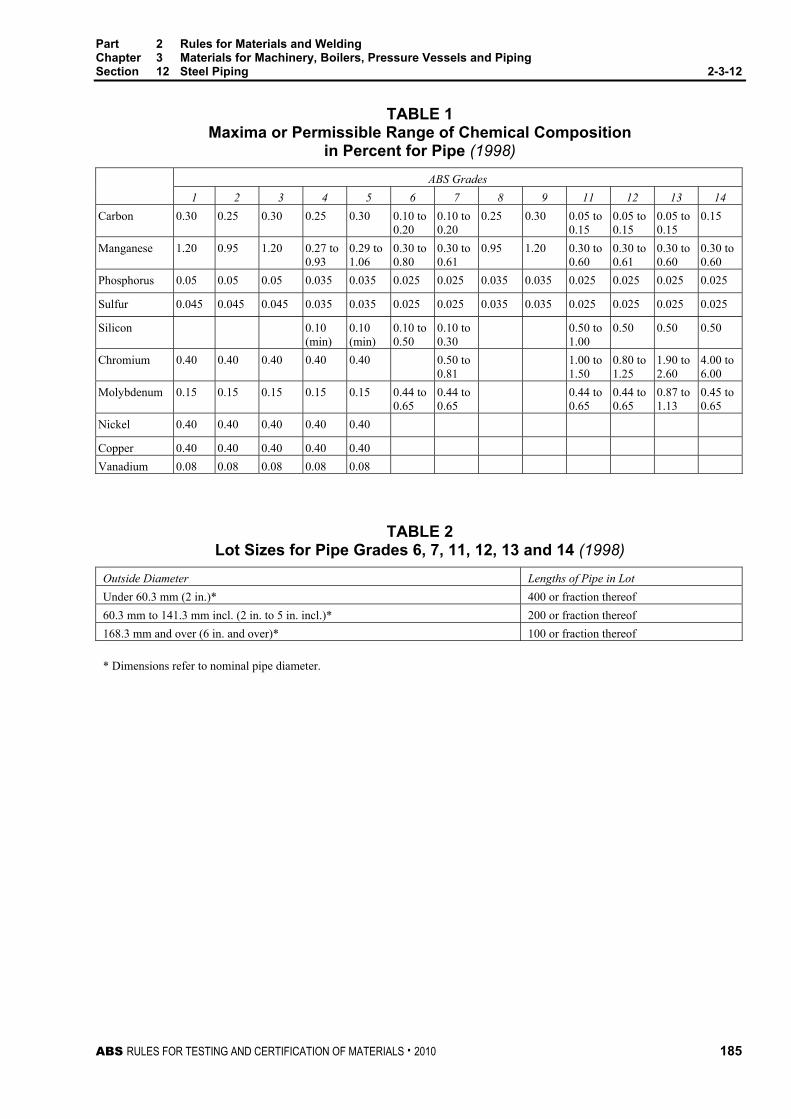
Part 2 Rules for Materials and Welding Chapter 3 Materials for Machinery, Boilers, Pressure Vessels and Piping Section 12 Steel Piping 2-3-12
ABS RULES FOR TESTING AND CERTIFICATION OF MATERIALS . 2010 185
TABLE 1 Maxima or Permissible Range of Chemical Composition
in Percent for Pipe (1998) ABS Grades 1 2 3 4 5 6 7 8 9 11 12 13 14
Carbon 0.30 0.25 0.30 0.25 0.30 0.10 to 0.20
0.10 to 0.20
0.25 0.30 0.05 to 0.15
0.05 to 0.15
0.05 to 0.15
0.15
Manganese 1.20 0.95 1.20 0.27 to 0.93
0.29 to 1.06
0.30 to 0.80
0.30 to 0.61
0.95 1.20 0.30 to 0.60
0.30 to 0.61
0.30 to 0.60
0.30 to 0.60
Phosphorus 0.05 0.05 0.05 0.035 0.035 0.025 0.025 0.035 0.035 0.025 0.025 0.025 0.025
Sulfur 0.045 0.045 0.045 0.035 0.035 0.025 0.025 0.035 0.035 0.025 0.025 0.025 0.025
Silicon 0.10 (min)
0.10 (min)
0.10 to 0.50
0.10 to 0.30
0.50 to 1.00
0.50 0.50 0.50
Chromium 0.40 0.40 0.40 0.40 0.40 0.50 to 0.81
1.00 to 1.50
0.80 to 1.25
1.90 to 2.60
4.00 to 6.00
Molybdenum 0.15 0.15 0.15 0.15 0.15 0.44 to 0.65
0.44 to 0.65
0.44 to 0.65
0.44 to 0.65
0.87 to 1.13
0.45 to 0.65
Nickel 0.40 0.40 0.40 0.40 0.40
Copper 0.40 0.40 0.40 0.40 0.40 Vanadium 0.08 0.08 0.08 0.08 0.08
TABLE 2 Lot Sizes for Pipe Grades 6, 7, 11, 12, 13 and 14 (1998)
Outside Diameter Lengths of Pipe in Lot Under 60.3 mm (2 in.)* 400 or fraction thereof 60.3 mm to 141.3 mm incl. (2 in. to 5 in. incl.)* 200 or fraction thereof 168.3 mm and over (6 in. and over)* 100 or fraction thereof * Dimensions refer to nominal pipe diameter.

Part 2 Rules for Materials and Welding Chapter 3 Materials for Machinery, Boilers, Pressure Vessels and Piping Section 12 Steel Piping 2-3-12
186 ABS RULES FOR TESTING AND CERTIFICATION OF MATERIALS . 2010
TABLE 3 Mechanical Tests for Pipe (1998)
Grade Type of Test Number of Tests 1, 2, 3 Tension (Longitudinal) One test on one length of pipe from each lot of 500 lengths or fraction thereof of each size. Transverse Weld
Tension (1) As for tension test, only for electric-resistance-welded pipe 219.1 mm in outside diameter (8 in. nominal diameter) and over.
Bend (1) As for tension test, only for pipe 60.3 mm in outside diameter (2 in. nominal diameter) and under, except not required for double-extra- strong-pipe over 42.2 mm in outside diameter (1-1/4 in. nominal diameter). As for tension test except: 1 Not required for pipe 60.3 mm in outside diameter (2 in. nominal diameter) and under. 2 Not required for double-extra strong pipe. 3 In the case of welded pipe ordered for flanging and electric-resistance-welded pipe, the crop ends cut from each length are to be subjected to this test.
Flattening
4 (1998) When pipe is produced in multiple lengths, tests are required on the crop ends from the front and back ends of each coil and on two tests are required on the crop ends from the intermediate rings representing each coil.
Hydrostatic (1) All pipes. 4, 5 Tension
(Longitudinal or Transverse (5))
One test on one length of pipe from each lot (2) of 400 lengths or fraction thereof of each size under 168.3 mm in outside diameter (6 in. Nominal diameter) and one test on one length of pipe from each lot of 200 lengths or fraction thereof of each size 168.3 mm in outside diameter (6 in. nominal diameter) and over.
Bend (1) One test on one length of pipe from each lot (2) of 400 lengths or fraction thereof of each size 60.3 mm in outside diameter (2 in. nominal diameter) and under, except not required for double-extra-strong pipe over 42.2 mm in outside diameter (1-1/4 in. nominal diameter.)
Flattening As for tension test, only for pipe over 60.3 mm in outside diameter (2 in. diameter). Hydrostatic (1) All pipes. 6, 7, 11, 12, 13, 14 (1998)
Tension (Longitudinal or Transverse (5))
One test on 5% of the pipe in a lot (3). For the pipe heat-treated in a batch-type furnace, at least one pipe from each heat-treated lot (3). For pipe heat-treated by continuous process, at least two pipes from each heat-treated lot(3) are to be tested.
Flattening As for tension test. Hydrostatic (1) All pipes. 8, 9 Tension
(Longitudinal) One test on one length of pipe from each of 400 lengths or fraction thereof of each size 168.3 mm in outside diameter (6 in. nominal diameter) and one test on one length of pipe from each lot of 200 lengths or fraction thereof of each size from 168.3 mm in outside diameter (6 in. nominal diameter) to and including 508 mm (20 in.) in outside diameter and one test on one length of pipe from each lot of 100 length or fraction thereof of each size over 508 mm (20 in.) in outside diameters.(4)
Transverse (1) Weld Tension
As for tension test, only for pipe 168.3 mm in outside diameter (6 in. nominal diameter) and over.(4)
Flattening One test on each of both crop ends cut from each length of pipe. When pipe is produced in multiple lengths, tests are required on the crop ends from the front and back ends of each coil and on two intermediate rings representing each coil.
Hydrostatic (1) All pipes.
Notes 1 Pipes intended for structural use, such as stanchions, need not be subjected to this test.
2 A lot, in this case, consists of all pipe of the same size and wall thickness from any one heat.
3 The term “lot” used here applies to all pipe of the same nominal size and wall thickness which is produced from the same heat of steel and subjected to the same finishing heat treatment in a continuous furnace. When the final heat treatment is in a batch-type furnace, the lot is to include only that pipe which is heat-treated in the same furnace charge. When no heat treatment is performed following the forming operations, the lot is to include hot-rolled material only or cold-drawn material only.
4 When taken from the skelp, the number of tests is to be determined in the same manner as when taken from finished pipe.
5 The transverse tension test may not be made on pipe under 219.1 mm in outside diameter (8 inch nominal diameter).

Part 2 Rules for Materials and Welding Chapter 3 Materials for Machinery, Boilers, Pressure Vessels and Piping Section 12 Steel Piping 2-3-12
ABS RULES FOR TESTING AND CERTIFICATION OF MATERIALS . 2010 187
TABLE 4 Tensile Requirements for Pipe (1998)
SI Units & MKS Units ABS Grades 1 2 (c) 3 (c) 4 5 6
and 7
8 (b) 9 (b) 11, 12, 13, 14
(1998)
310 330 415 330 415 380 330 415 415 Tensile Strength, min. N/mm2
(kgf/mm2) (31.5) (33.7) (42) (33.7) (42) (39) (33.7) (42) (42)
170 205 240 205 240 205 205 240 205
Yield Strength, min. N/mm2
(kgf/mm2) (17.5) (21) (24.5) (21) (24.5) (21) (21) (24.5) (21)
Elongation in 200 mm, min., % 20 (a)
Elongation in 50 mm. min., percent. Basic minimum elongation for walls 7.9 mm and over, strip tests, and for all small sizes tested in full section.
25 16.5 20 20 Transverse Longitudinal 35 30 35 30 30 35 30 30
When standard round 50 mm gauge length test specimen is used.
20 12 14 14 Transverse Longitudinal 30 28 22 28 22 22 22
Deduction in elongation for each 0.8 mm decrease in wall thickness below 7.9 mm for strip test.
1.25 1.00 1.00 1.00 Transverse Longitudinal 1.75 1.50 1.75 1.50 1.50 1.75 1.50 1.50
Notes a Gauge distances for measuring elongation on pipe of 26.7 mm O.D. and smaller are to be as
follows:
O.D. Gauge Length 26.7 mm and 21.3 mm 150 mm 17.1 mm and 13.7 mm 100 mm
103 mm 50 mm
b The test specimen taken across the weld is to show a tensile strength not less than the minimum specified for the grade pipe ordered. This test will not be required for pipe under 168.3 mm in outside diameter.
c The test specimen taken across the weld is to show a tensile strength not less than the minimum specified for the grade of pipe ordered. This test will not be required for pipe under 219.1 mm in outside diameter.

Part 2 Rules for Materials and Welding Chapter 3 Materials for Machinery, Boilers, Pressure Vessels and Piping Section 12 Steel Piping 2-3-12
188 ABS RULES FOR TESTING AND CERTIFICATION OF MATERIALS . 2010
TABLE 4 (continued) Tensile Requirements for Pipe (1998)
US Units ABS Grades 1 2 (c) 3 (c) 4 5 6
and 7
8 (b) 9 (b) 11, 12, 13, 14
(1998) 45000 48000 60000 48000 60000 55000 48000 60000 60000 Tensile Strength,
min., psi
25000 30000 35000 30000 35000 30000 30000 35000 30000 Yield Strength, min. psi
20 (a) Elongation in 8 in., min., %
Elongation in 2 in. min., percent. Basic minimum elongation for walls 5/16 in. and over, strip tests, and for all small sizes tested in full section.
25 16.5 20 20 Transverse Longitudinal 35 30 35 30 30 35 30 30
When standard round 2 in. gauge length test specimen is used.
20 12 14 14 Transverse Longitudinal 30 28 22 28 22 22 22
Deduction in elongation for each 1/32 in. decrease in wall thickness below 5/16 in. for strip test.
1.25 1.00 1.00 1.00 Transverse Longitudinal 1.75 1.50 1.75 1.50 1.50 1.75 1.50 1.50
Notes a Gauge distances for measuring elongation on pipe of nominal sizes 3/4 in. and smaller are to be
as follows:
Nominal Size Gauge Length 3/4 in. and 1/2 in. 6 in. 3/8 in. and 1/4 in. 4 in.
1/8 in. 2 in.
b The test specimen taken across the weld is to show a tensile strength not less than the minimum specified for the grade pipe ordered. This test will not be required for pipe under 6 in. in nominal diameter.
c The test specimen taken across the weld is to show a tensile strength not less than the minimum specified for the grade of pipe ordered. This test will not be required for pipe under 8 in. in nominal diameter.

Part 2 Rules for Materials and Welding Chapter 3 Materials for Machinery, Boilers, Pressure Vessels and Piping Section 12 Steel Piping 2-3-12
ABS RULES FOR TESTING AND CERTIFICATION OF MATERIALS . 2010 189
TABLE 5 Hydrostatic-test Pressure for Welded and Seamless Plain-end Steel Pipe SI Units Pressure in bars
Standard Weight
Extra-strong
Double Extra-strong
Outside Diameter, mm Grade Grade Grade Grade Grade Grade Grade Grade Grade 1 2 3 1 2 3 1 2 3 10.3 to 33.4 48 48 48 59 59 59 69 69 69 42.2 and 48.3 69 69 76 90 103 110 97 124 131 60.3 69 159 172 90 172 172 97 172 172 73.0 69 172 172 90 172 172 97 172 172 88.9 69 152 172 90 172 172 172 172 101.6 83 138 165 117 193 193 114.3 83 131 152 117 186 193 193 193 141.3 117 131 165 193 193 193 168.3 103 124 159 186 193 193 219.1 90 110 145 165 193 193 273.1 83 97 117 138 193 193 323.9 76 83 97 110 193 193 355.6 66 76 90 103 406.4 59 69 76 90 457.2 52 62 69 83 508.0 48 55 62 69 609.6 38 45 52 62
MKS Units Pressure in kgf/cm2
Standard Weight
Extra-strong
Double Extra-strong
Outside Diameter, mm Grade Grade Grade Grade Grade Grade Grade Grade Grade 1 2 3 1 2 3 1 2 3 10.3 to 33.4 49.2 49.2 49.2 59.8 59.8 59.8 70.3 70. 3 70.3 42.2 and 48.3 70.3 70.3 77.3 91.3 103 112 98.4 124 134 60.3 70.3 162 176 91.4 176 176 98.4 176 176 73.0 70.3 176 176 91.4 176 176 98.4 176 176 88.9 70.3 155 176 91.4 176 176 176 176 101.6 84.4 141 169 120 197 197 114.3 84.4 136 155 120 190 190 197 197 141.3 120 136 169 197 197 197 168.3 105 127 162 190 197 197 219.1 91.4 112 148 169 197 197 273.1 84.4 98.4 120 141 197 197 323.9 77.3 84.4 98.4 112 197 197 355.6 66.8 77.3 91.4 105 406.4 59.8 70.3 77.3 91.4 457.2 52.7 63.3 70.3 84.4 508.0 49.2 56.2 63.3 70.3 609.6 38.7 45.7 52.7 63.3

Part 2 Rules for Materials and Welding Chapter 3 Materials for Machinery, Boilers, Pressure Vessels and Piping Section 12 Steel Piping 2-3-12
190 ABS RULES FOR TESTING AND CERTIFICATION OF MATERIALS . 2010
TABLE 5 (continued) Hydrostatic-test Pressure for Welded and Seamless Plain-end Steel Pipe US Units Pressure in psi IPS Size, in.
Standard Weight
Extra-strong
Double Extra-strong
Grade Grade Grade Grade Grade Grade Grade Grade Grade 1 2 3 1 2 3 1 2 3 1/8 to 1 700 700 700 850 850 850 1000 1000 1000 11/4 and 11/2 1000 1000 1100 1300 1500 1600 1400 1800 1900 2 1000 2300 2500 1300 2500 2500 1400 2500 2500 21/2 1000 2500 2500 1300 2500 2500 1400 2500 2500 3 1000 2200 2500 1300 2500 2500 2500 2500 31/2 1200 2000 2400 1700 2800 2800 4 1200 1900 2200 1700 2700 2800 2800 2800 5 1700 1900 2400 2800 2800 2800 6 1500 1800 2300 2700 2800 2800 8 1300 1600 2100 2400 2800 2800 10 1200 1400 1700 2000 2800 2800 12 1100 1200 1400 1600 2800 2800 14 950 1100 1300 1500 16 850 1000 1100 1300 18 750 900 1000 1200 20 700 800 900 1000 24 550 650 750 900
TABLE 6 Out-of-roundness Variation (1998)
Millimeters Out-of-roundness Variation Pipe Outside Diameter Over Under 10.3 to 48.3 incl. 0.38 0.79 Over 48.3 to 114.3 incl. 0.79 0.79 Over 114.3 to 219.1 incl. 1.57 0.79 Over 219.1 to 457.2 incl. 2.36 0.79 Over 457.2 to 660.4 incl. 3.17 0.79 Over 660.4 to 863.6 incl. (1998) 4.0 0.8 Over 863.6 to 1219.2 incl. (1998) 4.8 0.8
Inches Out-of-roundness Variation Nominal Pipe Size Over Under 1/8 to 11/2 incl. 1/64 (0.015) 1/32 (0.031) Over 11/2 to 4 incl. 1/32 (0.031) 1/32 (0.031) Over 4 to 8 incl. 1/16 (0.062) 1/32 (0.031) Over 8 to 18 incl. 3/32 (0.093) 1/32 (0.031) Over 18 to 26 incl. 1/8 (0.125) 1/32 (0.031) Over 26 to 34 incl. (1998) 5/32 (0.156) 1/32 (0.031) Over 34 to 48 incl. (1998) 3/16 (0.187) 1/32 (0.031)
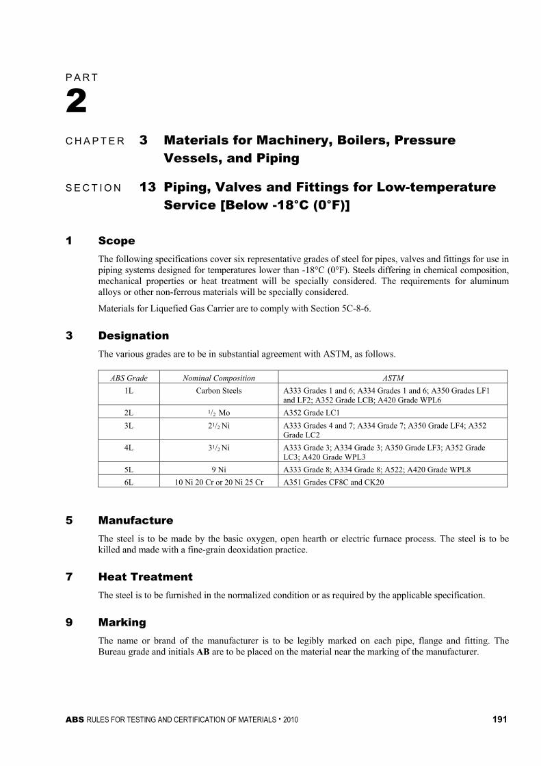
ABS RULES FOR TESTING AND CERTIFICATION OF MATERIALS . 2010 191
P A R T Section 13:Piping, Valves and Fittings for Low-temperature Service [Below -18°C (0°F)]
2 C H A P T E R 3 Materials for Machinery, Boilers, Pressure
Vessels, and Piping
S E C T I O N 13 Piping, Valves and Fittings for Low-temperature Service [Below -18°C (0°F)]
1 Scope The following specifications cover six representative grades of steel for pipes, valves and fittings for use in piping systems designed for temperatures lower than -18°C (0°F). Steels differing in chemical composition, mechanical properties or heat treatment will be specially considered. The requirements for aluminum alloys or other non-ferrous materials will be specially considered.
Materials for Liquefied Gas Carrier are to comply with Section 5C-8-6.
3 Designation The various grades are to be in substantial agreement with ASTM, as follows.
ABS Grade Nominal Composition ASTM 1L Carbon Steels A333 Grades 1 and 6; A334 Grades 1 and 6; A350 Grades LF1
and LF2; A352 Grade LCB; A420 Grade WPL6 2L 1/2 Mo A352 Grade LC1 3L 21/2 Ni A333 Grades 4 and 7; A334 Grade 7; A350 Grade LF4; A352
Grade LC2 4L 31/2 Ni A333 Grade 3; A334 Grade 3; A350 Grade LF3; A352 Grade
LC3; A420 Grade WPL3 5L 9 Ni A333 Grade 8; A334 Grade 8; A522; A420 Grade WPL8 6L 10 Ni 20 Cr or 20 Ni 25 Cr A351 Grades CF8C and CK20
5 Manufacture The steel is to be made by the basic oxygen, open hearth or electric furnace process. The steel is to be killed and made with a fine-grain deoxidation practice.
7 Heat Treatment The steel is to be furnished in the normalized condition or as required by the applicable specification.
9 Marking The name or brand of the manufacturer is to be legibly marked on each pipe, flange and fitting. The Bureau grade and initials AB are to be placed on the material near the marking of the manufacturer.

Part 2 Rules for Materials and Welding Chapter 3 Materials for Machinery, Boilers, Pressure Vessels and Piping Section 13 Piping, Valves and Fittings for Low-temperature Service 2-3-13
192 ABS RULES FOR TESTING AND CERTIFICATION OF MATERIALS . 2010
11 Chemical Composition The materials selected from 2-3-13/3 are to conform to the chemical requirements given in the ASTM designation indicated, except as modified by 2-3-13/5 or otherwise specially approved.
13 Mechanical Tests The materials selected from 2-3-13/3 are to be tested in accordance with the requirements of the applicable ASTM designation as to tension test, hydrostatic test, flattening test, etc., unless otherwise specially approved.
15 Impact Properties The materials selected from 2-3-13/3 are to conform to the toughness requirements of 2-3-13/23.
17 Steels for Service Temperatures Between -18°C (0°F) and -196°C (-320°F) The following grades may be used for the minimum design service temperature indicated.
Grade Minimum Design Service Temperature °C (°F) 1L -34 (-30) 2L -46 (-50) 3L -73 (-100) 4L -101 (-150)
5L & 6L -196 (-320)
19 Steels for Service Temperatures Below -196°C (-320°F) Steels intended for service temperatures below -196°C (-320°F) are to be austenitic stainless steels. The chemical composition, heat treatment and tensile properties of these materials are to be submitted for each application.
21 Materials for Nuts and Bolts Ferritic-alloy nuts and bolts conforming to ASTM A194 Grade 4 and A320 L43 may be used where system service temperatures are not below -101°C (-150°F). Austenitic-alloy nuts and bolts conforming to ASTM A194 Grades 8T and 8F and A320 Grades B8T, B8F and B8M may be used where the design service temperature is not below -196°C (-320°F).
23 Toughness Low temperature notch toughness is to be determined by impact testing using Charpy V-notch specimens. Testing is to consist of at least three longitudinally oriented specimens from each lot. Lot size is as defined in the applicable ASTM designation, except that at least one set of impact tests is to be made from each heat in each heat treatment charge. The energies absorbed by each set of impact specimens for Grades 1L and 2L is to conform to the requirements specified below.
Specimen Size Minimum Average Minimum-One Specimen mm J (kgf-m, ft-lbf) J (kgf-m, ft-lbf)
10 × 10 27.0 (2.8, 20) 18.5 (1.9, 13.5) 10 × 7.5 22.5 (2.3, 16.5) 15.0 (1.5, 11) 10 × 5.0 18.5 (1.9, 13.5) 12.0 (1.2, 9) 10 × 2.5 13.5 (1.4, 10) 9.0 (0.9, 6.5)

Part 2 Rules for Materials and Welding Chapter 3 Materials for Machinery, Boilers, Pressure Vessels and Piping Section 13 Piping, Valves and Fittings for Low-temperature Service 2-3-13
ABS RULES FOR TESTING AND CERTIFICATION OF MATERIALS . 2010 193
The Charpy impact requirements for Grades 3L, 4L and 5L are 125% of the values shown above. Charpy impact tests are not required for Grade 6L. Where material thicknesses are such that the quarter size impact specimen cannot be obtained, the requirements for toughness testing will be specially considered.
25 Impact Test Temperature Materials selected from 2-3-13/3 are not to be used at temperatures lower than those indicated in 2-3-13/17 and are to be tested at temperatures at least 5.5°C (10°F) below the minimum design service temperature. Where the test temperature is determined to be below -196°C (-320°F), testing may be conducted at -196°C (-320°F).
27 Witnessed Tests (2006) Piping intended for temperature below -18°C (0°F) is to be tested in the presence of the Surveyor. Materials intended for fabrication of valves fittings and piping are to be tested by the manufacturers and, upon request, the test results are to be submitted to the Bureau.
For vessels intended to carry Liquefied Gases in Bulk, see 5C-8-6/1.3.
29 Retests When the material fails to meet the minimum impact requirements of 2-3-13/23 by an amount not exceeding 15%, retests are permitted in accordance with 2-1-2/11.7.
31 Welding Weld procedure is to be approved in accordance with the requirements of 2-4-3/5.3. See also 2-4-2/9.9.

194 ABS RULES FOR TESTING AND CERTIFICATION OF MATERIALS . 2010
P A R T S e c t i o n 1 4 : B r o n z e C a s t i n g s
2 C H A P T E R 3 Materials for Machinery, Boilers, Pressure
Vessels, and Piping
S E C T I O N 14 Bronze Castings
1 For General Purposes
1.1 Tensile Properties The castings are to be free from injurious defects. The material is to have the following tensile properties.
Type
Tensile Strength Minimum, N/mm2 (kgf/mm2, psi)
Elongation in 50 mm (2 in.) Minimum percent
Stamping
1 205 (21, 30000) 15 AB/1
1.3 Number of Tests At least one tension test is to be made from each melt and the tension test specimen is to be machined to the dimensions shown in 2-3-1/Figure 2.
3 Propellers and Propeller Blades
3.1 Foundry Approval (2006) 3.1.1 Approval
All propellers and propeller components are to be cast by Bureau-approved foundries. For this purpose, the foundries are to demonstrate that they have available the necessary facilities and skilled personnel to enable proper manufacture of propellers which will satisfy these Rules.
3.1.2 Scope of the Approval Test The following aspects of manufacture are to be taken into account:
• Casting types and sizes
• Material specifications
• Repair procedures
• Ladle capacities
• Manufacturing practices and procedures for melting and pouring, molding, heat treatment, welding repairs, hot and cold straightening, destructive and nondestructive testing methods and equipment, and chemical and metallographic capabilities.
Cast coupons of the propeller materials involved are to be tested in order to verify that composition and mechanical properties comply with these Rules.
3.1.3 Quality Control In addition, information as to the company’s facilities and organization, especially as they relate to quality control, is also required to be presented, including certification in accordance with national or international standards, such as ISO standards.

Part 2 Rules for Materials and Welding Chapter 3 Materials for Machinery, Boilers, Pressure Vessels and Piping Section 14 Bronze Castings 2-3-14
ABS RULES FOR TESTING AND CERTIFICATION OF MATERIALS . 2010 195
3.2 Castings The castings are to be free from defects.
3.3 Chemical Composition The chemical composition in % is to conform to an approved specification, four of which are listed in the table below as representative of bronze alloys currently used for propellers and propeller blades. See also 2-3-14/3.19. The samples for chemical analysis may be taken from test coupons or representative castings.
Type 2
Mn Bronze
Type 3 Ni-Mn Bronze
Type 4 Ni-Al
Bronze
Type 5 Mn-Ni-Al
Bronze Copper 55–60 53.5–57 78 min 71 min Tin 1.00 max 1.00 max — — Lead 0.40 max 0.20 max 0.03 max 0.03 max Iron 0.4–2.0 1.0–2.5 3.0–5.0 2.0–4.0 Manganese 1.5 max 2.5–4.0 3.5 max 11.0–14.0 Aluminum 0.5–1.5 2.0 max 8.5–11.0 7.0–8.5 Nickel 0.5 max 2.5–4.0 3.0–5.5 1.5–3.0 Silicon — — — 0.10 max Zinc Remainder Remainder — — Total Others — — 0.50 max 0.50 max
3.5 Zinc Equivalent The chemical composition of Type 2 and Type 3 alloys are to be so controlled that the zinc equivalent, based on the following equation, does not exceed 45.0%.
% zinc equivalent = 100 − ⎟⎠⎞
⎜⎝⎛
+×
Acopper
100%100
where A is the algebraic sum of the following zinc replacement factors:
Tin = +1.0 × % Sn
Iron = -0.1 × % Fe
Aluminum = +5.0 × % Al
Lead = 0.0
Manganese = -0.5 × % Mn
Nickel = -2.3 × % Ni
3.7 Alternative Zinc Equivalent When the alpha content of a specimen taken from the end of the acceptance test bar is determined by microscopic measurement to be 20% or more, the foregoing ‘‘zinc equivalent’’ requirement will be waived.
3.9 Tensile Properties (2008) The material represented by the test specimens machined from separately cast test coupons is to conform to the following minimum tensile properties.

Part 2 Rules for Materials and Welding Chapter 3 Materials for Machinery, Boilers, Pressure Vessels and Piping Section 14 Bronze Castings 2-3-14
196 ABS RULES FOR TESTING AND CERTIFICATION OF MATERIALS . 2010
Tensile Properties of Separately Cast Test Coupons (1,2) Elongation (4) Min. percent
Tensile Strength Yield Strength (3)
Gauge Length Type N/mm2 (kgf/mm2, psi) N/mm2 (kgf/mm2, psi) 4d 5d
2 450 (46, 65,000) 175 (18, 25,000) 20 18 3 515 (53, 75,000) 220 (22.5, 32,000) 18 16 4 590 (60, 86,000) 245 (25, 36,000) 16 15 5 630 (64, 91,000) 275 (28, 40,000) 20 18
Notes 1 These properties are generally not representative of the tensile properties of the propeller casting itself, which
could be substantially lower than that of a separately cast test coupon.
2 The tensile requirements of integral-cast test coupons are to be specially approved.
3 Yield strength is to be determined in accordance with 2-3-1/13.3.
4 See 2-3-1/Figure 2.
3.11 Test Specimens (2008) The test-coupon casting from which the tensile test specimen is machined is to be of an approved form. The tensile test specimen is to be machined to the dimensions shown in 2-3-1/Figure 1 (Round Specimen Alternative C). The test coupons may be separately cast or integral with the casting.
3.13 Separately Cast Coupons (1996) Separately cast test coupons, as shown in 2-3-14/Figure 1 (test coupon according to the broken line may also be accepted) or in accordance with a recognized national standard, are to be poured from the same ladles of metal used to pour the castings, and into molds of the same material as used for the casting. In cases where more than one ladle of metal is required for a casting, a test coupon is to be provided for each ladle. Satisfactory evidence is to be furnished the Surveyor to identify the test coupons as representing the material to be tested.
3.15 Integrally Cast Coupons Integrally cast coupons are to be furnished as coupons cast on the surfaces of the castings.
3.17 Number of Tests One tension test is to be made for each casting when integrally cast test coupons are provided and one tension test is to be made from each ladle when separately cast test coupons are provided. The test results are to comply with the requirements prescribed in 2-3-14/3.9.
3.19 Special Compositions It is recognized that other bronze alloys have been developed and proven by tests and service experience to be satisfactory. When propeller materials not meeting the chemical compositions in 2-3-14/3.3 are proposed, specifications are to be submitted for approval in connection with the approval of the design for which the material is intended.
3.21 Inspection and Repair The entire surface of the finished propeller is to be visually examined. A liquid penetrant examination of critical areas is to be made on all propellers over 2 m (78 in.) in diameter. In addition, liquid penetrant examination is to be conducted on all suspect areas. All inspections and repairs are to be to the satisfaction of the Surveyor. Conformity with Appendix 7-A-10, “Guidance Manual for Bronze and Stainless Steel Propeller Castings” of the ABS Rules for Survey After Construction (Part 7), will be considered to meet requirements for the inspection and repair of propeller castings.

Part 2 Rules for Materials and Welding Chapter 3 Materials for Machinery, Boilers, Pressure Vessels and Piping Section 14 Bronze Castings 2-3-14
ABS RULES FOR TESTING AND CERTIFICATION OF MATERIALS . 2010 197
FIGURE 1 Test Coupons (1996)
L
B
H
T
D
H = 100 mm (4 in.) B = 50 mm (2 in.) L > 150 mm (3 in.) T = 15 mm (0.59 in.) D = 25 mm (1 in.)
3.23 Marking The manufacturer’s name and other appropriate identification markings are to be stamped on each propeller or propeller blade in such location as to be discernible after finishing and assembly. In addition, Type 2, 3, 4 and 5 castings are to be stamped AB/2, AB/3, AB/4 or AB/5, respectively, to indicate satisfactory compliance with Rule requirements. Bronze alloys produced to specifications other than those covered herein in accordance with the permissibility expressed in 2-3-14/3.19 are to be stamped AB/S and with the applicable specification number.
5 Castings for Ice-Strengthened Propellers Castings for ice-strengthened propellers are to meet the requirements for bronze, carbon, alloy, or stainless steel propeller alloy, as applicable, and the following additional requirements.
Ice Strengthening Class Additional Requirements All ice classes except ice class D0 Minimum Charpy V-Notch absorbed energy
20.5 J (2.1 kgf-m, 15 ft-lbs) at -10°C (14°F) 19% minimum elongation in 5D

198 ABS RULES FOR TESTING AND CERTIFICATION OF MATERIALS . 2010
P A R T S e c t i o n 1 5 : A u s t e n i t i c S t a i n l e s s S t e e l P r o p e l l e r C a s t i n g s
2 C H A P T E R 3 Materials for Machinery, Boilers, Pressure
Vessels, and Piping
S E C T I O N 15 Austenitic Stainless Steel Propeller Castings
Note: In substantial agreement with ASTM A-743, Grade CF-3
1 Process of Manufacture and Foundry Approval (2006)
1.1 Process of Manufacture The following requirements cover austenitic stainless steel castings intended to be used for propellers and propeller blades. The stainless steel is to be melted by the electric arc or electric induction process, or other process as may be approved.
1.3 Foundry Approval Stainless steel propellers and propeller components, including grade CF-3 and other grades, as indicated in 7-A-10/3 of the ABS Rules for Survey After Construction (Part 7), are to be cast by Bureau-approved foundries. For this purpose, foundries are to demonstrate that they have available the necessary facilities and skilled personnel to enable proper manufacture of propellers which will satisfy these Rules.
1.5 Scope of the Approval Test The following aspects of manufacture are to be taken into account:
• Casting types and sizes
• Material specifications
• Repair procedures
• Ladle capacities
• Manufacturing practices and procedures for: Melting and pouring, molding, heat treatment, welding repairs, hot and cold straightening, destructive and nondestructive testing methods and equipment, and chemical and metallographic capabilities.
Cast coupons of the propeller materials involved are to be tested in order to verify that composition and mechanical properties comply with these Rules.
1.7 Quality Control In addition, information as to the company’s facilities and organization, especially as they relate to quality control, is required to be presented, including certification in accordance with national or international organizations standards, such as ISO standards.

Part 2 Rules for Materials and Welding Chapter 3 Materials for Machinery, Boilers, Pressure Vessels and Piping Section 15 Austenitic Stainless Steel Propeller Castings 2-3-15
ABS RULES FOR TESTING AND CERTIFICATION OF MATERIALS . 2010 199
3 Inspection and Repair The entire surface of the finished propeller is to be visually examined. A liquid penetrant examination of critical areas is to be made. In addition, all suspect areas should be examined by the liquid penetrant method. The surfaces of all propellers are to be suitably protected from the corrosive effects of industrial environments until fitted on the vessel. All inspections and repairs are to be to the satisfaction of the Surveyor. Conformity with Appendix 7-A-10, “Guidance Manual for Bronze and Stainless Steel Propeller Castings” of the ABS Rules for Survey After Construction (Part 7), will be considered to meet requirements for the inspection and repair of propeller castings.
5 Chemical Composition An analysis of each heat is to be made by the manufacturer from a test sample that is representative of the heat and that is taken during the pouring of the heat. The chemical composition in % thus determined is to conform to the requirements specified below.
Carbon max.* 0.03 Manganese max. 1.50 Silicon max. 2.00 Phosphorus max. 0.04 Sulfur max. 0.04 Chromium 17.0–21.0 Nickel 8.0–12.0
* A carbon content up to and including 0.0345% is considered to meet the 0.03 maximum requirement.
7 Tensile Properties The metal represented by the test specimens is to conform to the following minimum tensile properties.
Tensile Strength N/mm2 Yield Strength N/mm2 Elongation in Grade (kgf/mm2, psi) (kgf/mm2, psi) 50 mm (2 in.) % CF-3 485 (49, 70,000) 205 (21, 30,000) 35
9 Tests and Marking
9.1 Test Specimens The test-coupon casting from which the tension test specimen is machined is to be of an approved form. The tension test specimen is to be machined to the dimensions shown in 2-3-1/Figure 2. The test coupons may be separately or integrally cast.
9.3 Separately Cast Coupons (2006) Separately cast test coupons are to be poured from the same ladles of metal used to pour the castings, and into molds of the same material as used for the casting. Test coupons are to be heat treated with the castings represented. In cases where more than one ladle of metal is required for a casting, a test coupon is to be provided for each ladle. Satisfactory evidence is to be furnished the Surveyor to identify the test coupons as representing the material to be tested.

Part 2 Rules for Materials and Welding Chapter 3 Materials for Machinery, Boilers, Pressure Vessels and Piping Section 15 Austenitic Stainless Steel Propeller Castings 2-3-15
200 ABS RULES FOR TESTING AND CERTIFICATION OF MATERIALS . 2010
9.5 Integral Coupons (2006) Integral test coupons are to be furnished as coupons attached to the hub or on the blade. Where possible, test bars attached on blades are to be located in an area between 0.5 to 0.6R, where R is the radius of the propeller. Test bars are not to be detached from the casting until final heat treatment has been carried out. Removal is to be by non-thermal means.
9.7 Number of Tests One tension test is to be made for each casting when integrally cast test coupons are provided, and one tension test is to be made from each ladle when separately cast test coupons are provided. The test results are to comply with the requirements prescribed in 2-3-15/7.
9.9 Special Compositions It is recognized that other alloys have been developed and proven by tests and service experience to be satisfactory. When propeller materials not meeting the chemical compositions in 2-3-15/5 are proposed, specifications are to be submitted for approval in connection with the approval of the design for which the material is intended.
9.11 Marking The manufacturer’s name and other appropriate identification markings are to be stamped on each propeller or propeller blade in such location as to be discernible after finishing and assembly. In addition, Grade CF-3 castings are to be stamped AB/CF–3 to indicate satisfactory compliance with Rule requirements. Alloys produced to specifications other than those covered herein in accordance with the permissibility expressed in 2-3-15/9.9 are to be stamped AB/S, and with the applicable specification number.
11 Castings for Ice-strengthened Propellers Castings for ice-strengthened propellers are to comply with 2-3-14/5.

ABS RULES FOR TESTING AND CERTIFICATION OF MATERIALS . 2010 201
P A R T S e c t i o n 1 6 : S e a m l e s s C o p p e r P i p i n g
2 C H A P T E R 3 Materials for Machinery, Boilers, Pressure
Vessels, and Piping
S E C T I O N 16 Seamless Copper Piping (1998)
Note: In substantial agreement with ASTM B42.
1 Scope The following specifications cover seven grades of seamless copper pipe designated C1, C2, C3, C4, C5, C6 and C7.
3 General
3.1 Grades C1, C2, C3, C4, C5, C6 and C7 These grades cover seamless copper pipe intended for boiler feed-water lines, plumbing, and other similar service. Pipe ordered in all standard pipe sizes, both regular and extra strong, under these grades is considered suitable for welding and brazing.
3.3 ASTM Designation These grades are in substantial agreement with ASTM, as follows:
ABS Grade ASTM Designation C1 UNS C10100 C2 B42, UNS C10200 C3 B42, UNS C10300 C4 B42, UNS C10800 C5 B42, UNS C12000 C6 B42, UNS C12200 C7 UNS C14200
5 Process of Manufacture (2009) The material is to be produced by either hot or cold working operations, or both. It is to be finished, unless otherwise specified, by such cold working and annealing or heat treatment as may be necessary to meet the properties specified. All pipe is to be normally furnished in the drawn-temper condition, (H55). Hard-drawn temper (H80) may be furnished also. When pipe is required for bending, the pipe is to be furnished with a proper bending temper, or annealed temper (061). All pipes for working pressures over 10 bar (10.5 kgf/cm2, 150 psi) are to be tested and inspected at the mills to the satisfaction of the Surveyor. The pipes are examined by the Surveyor when requested by the purchaser. The pipe is to be commercially round and is to be free from defects that interfere with normal applications.

Part 2 Rules for Materials and Welding Chapter 3 Materials for Machinery, Boilers, Pressure Vessels and Piping Section 16 Seamless Copper Piping 2-3-16
202 ABS RULES FOR TESTING AND CERTIFICATION OF MATERIALS . 2010
7 Marking
7.1 Manufacturer’s Marking The name or brand of the manufacturer, the designation B42, and the test pressure are to be legibly marked by stamping or stenciling on each length of pipe. On small-diameter pipe, which is bundled, this information may be marked on a tag securely attached to each bundle.
7.3 Bureau Markings The Bureau markings, indicating satisfactory compliance with the Rule requirements, and as furnished by the Surveyor, are to be placed on the material near the markings specified in 2-3-16/7.1.
9 Chemical Composition The material is to conform to the applicable requirements as to chemical composition as shown in 2-3-16/Table 1.
11 Tension Test
11.1 Tension Test Specimens Tensile test specimens are to be a full section of the pipe. For larger sizes, tension test specimens are to consist of longitudinal strips cut from the pipe in accordance with ASTM E8.
11.3 Tensile Properties The material is to conform to the applicable requirements as to tensile properties shown in 2-3-16/Table 2.
13 Expansion Test Specimens selected for test, after annealing, are to withstand an expansion of 25% of the outside diameter when expanded by a tapered pin having a 60-degree included angle. The expanded tube is to show no cracking or rupture visible to the unaided eye.
15 Flattening Test As an alternate to the expansion test for pipe over 114.3 mm outside diameter (4 in. nominal size) in the annealed condition, a section 100 mm (4 in.) in length is to be cut from the end of one of the lengths for a flattening test. This 100 mm (4 in.) specimen is to be flattened so that a gauge set at three times the wall thickness will pass over the pipe freely throughout the flattened part. The pipe so tested is to develop no cracks or defects visible to the unaided eye as a result of this test. In making the flattening test, the specimens are to be slowly flattened by one stroke of the press.
17 Hydrostatic Test
17.1 Limiting Test Pressures Each length of the pipe is to stand, without showing weakness or defects, an internal hydrostatic pressure sufficient to subject the material to a fiber stress of 41 N/mm2 (4.22 kgf/mm2, 6000 psi), determined by the following equation. No pipe is to be tested beyond a hydrostatic pressure of 69 bar (70.3 kgf/cm2, 1000 psi) unless so specified. At the option of the manufacturer, annealed pipe with wall thickness up to 2.11 mm (0.083 in.) inclusive may be tested in the hard-drawn condition prior to annealing.
P = KSt/(D − 0.8t)

Part 2 Rules for Materials and Welding Chapter 3 Materials for Machinery, Boilers, Pressure Vessels and Piping Section 16 Seamless Copper Piping 2-3-16
ABS RULES FOR TESTING AND CERTIFICATION OF MATERIALS . 2010 203
where
P = pressure in bar (kgf/cm2, psi)
S = allowable unit stress of the material, 41 N/mm2 (4.22 kgf/mm2, 6000 psi)
t = thickness of pipe wall, in mm (in.)
D = outside diameter of the pipe, in mm (in.)
K = 20 (200, 2)
17.3 Affidavits of Tests Where each pipe is hydrostatically tested as a regular procedure during the process of manufacture, an affidavit covering this test may be accepted by the Surveyor.
19 Number of Tests The lot is to consist of pipe of the same size and temper. The lot size is to be 2270 kg (5000 lb) or a fraction thereof for pipe up to 48.3 mm O.D. (1.5 in. nominal size) incl.; 4550 kg (10,000 lb) or a fraction thereof for pipe over 48.3 mm O.D. (1.5 in. nominal size) to 114.3 mm O.D. (4 in. nominal size) incl., 18,150 kg (40,000 lb) or a fraction thereof for pipe over 114.3 mm O.D. (4 in. nominal size). Sample pieces are to be taken for test purposes from each lot as follows:
Number of Pieces in Lot Number of Sample Pieces to Be Taken 1 to 50 1
51 to 200 2 201 to 1500 3 Over 1500 0.2% of total number of pieces in the lot, but not to exceed 10 sample pieces
Chemical analyses, where required, tensile tests, expansion tests, flattening tests, bend tests, where required, dimensional examinations and visual examinations are to be made on each of the sample pieces selected for test. Each length of pipe is to be subjected to the hydrostatic test specified in 2-3-16/17.
21 Retests If the results of the test on one of the specimens, made to determine the mechanical properties, fails to meet the requirements, this test is to be repeated on each of two additional specimens taken from different pieces and the results of both of these tests is to comply with the requirements. Failure of more than one specimen to meet the requirements for a particular property is to be cause for rejection of the entire lot.
23 Permissible Variations in Dimensions The permissible variations in wall thickness and diameter are based on the ordered thickness and are to conform to that given in the applicable ASTM designation for acceptance, but the minimum thickness for all pipe is not to be less than that required by the Rules for a specific application, regardless of such prior acceptance.

Part 2 Rules for Materials and Welding Chapter 3 Materials for Machinery, Boilers, Pressure Vessels and Piping Section 16 Seamless Copper Piping 2-3-16
204 ABS RULES FOR TESTING AND CERTIFICATION OF MATERIALS . 2010
TABLE 1 Chemical Composition for Copper Pipe and Tube (1998)
Pipe Grade
Tube Grade
Minimum Copper*, %
Phosphorus, %
Arsenic, %
Maximum Oxygen, ppm
C1 CA 99.99 — — — C2 CB 99.5 — — 10 C3 CC 99.95** 0.001 to 0.005 — — C4 CD 99.95** 0.005 to 0.012 — — C5 CE 99.90 0.004 to 0.012 — — C6 CF 99.9 0.015 to 0.040 — — C7 CG 99.40 0.015 to 0.040 0.15-0.50 —
Notes: * Including silver.
** Total of copper, silver and phosphorus.
TABLE 2 Tensile Properties for Copper Pipe and Tube (1998)
Temper Designation Tensile Strength, min Yield Strength*, min. Standard Former N/mm2 (kgf/mm2, ksi) N/mm2 (kgf/mm2, ksi) 061/060 annealed 205 (21,30) 62 (6,9)**
H55 light drawn 250 (25,36) 205 (21,30) H80 hard drawn 310 (32,45) 275 (28,40)
Notes: * At 0.5% extension under load.
** Light straightening operation is permitted.

ABS RULES FOR TESTING AND CERTIFICATION OF MATERIALS . 2010 205
P A R T S e c t i o n 1 7 : S e a m l e s s R e d - b r a s s P i p i n g
2 C H A P T E R 3 Materials for Machinery, Boilers, Pressure
Vessels, and Piping
S E C T I O N 17 Seamless Red-brass Piping
Note: In substantial agreement with ASTM B43.
1 Process of Manufacture (2009) The material is to be produced by either hot or cold working operations, or both. It is to be finished, unless otherwise specified, by such cold working and annealing or heat treatment as may be necessary to meet the properties specified. All pipe is normally to be furnished in the annealed condition. The degree of anneal is to be sufficient to show complete recrystallization and to enable the pipe to meet the test requirements prescribed in these specifications. The pipe may be furnished in the drawn-temper condition instead of the annealed condition if so specified by the purchaser. All pipes for working pressures over 10 bar (10.5 kgf/cm2, 150 psi) are to be tested and inspected at the mills to the satisfaction of the Surveyor. The pipes are examined by the Surveyor when requested by the purchaser. The pipe is to be commercially round and is to be free from defects that interfere with normal applications.
3 Marking
3.1 Manufacturer’s Marking The name or brand of the manufacturer, the designation B43, and the test pressure is to be legibly marked by stamping or stenciling on each length of pipe. On small-diameter pipe, which is bundled, this information may be marked on a tag securely attached to each bundle.
3.3 Bureau Marking The Bureau markings, indicating satisfactory compliance with the Rule requirements, and as furnished by the Surveyor, are to be marked on the material near the markings specified in 2-3-17/3.1.
5 Scope These specifications cover seamless red-brass pipe in all standard sizes, both regular and extra strong.
7 Chemical Composition The material is to conform to the following requirements as to chemical composition.
Copper 84.00% to 86.00% Lead 0.06% max. Iron 0.05% max. Zinc remainder Total other elements 0.15%
Analysis is regularly to be made only for the elements specifically mentioned in this table. If, however, the presence of other elements is suspected or indicated in the course of routine analysis, further analysis is to be made to determine that the total of these other elements is not in excess of the limit specified.

Part 2 Rules for Materials and Welding Chapter 3 Materials for Machinery, Boilers, Pressure Vessels and Piping Section 17 Seamless Red-brass Piping 2-3-17
206 ABS RULES FOR TESTING AND CERTIFICATION OF MATERIALS . 2010
9 Expansion Test Specimens selected for test, after annealing, are to withstand an expansion of 25% of the inside diameter, without cracking, when expanded by a tapered pin having a 60-degree included angle. The expanded tube is to show no cracking or rupture visible to the unaided eye.
11 Flattening Test As an alternate to the expansion test for pipe over 114.3 mm outside diameter (4 in. nominal size) in the annealed condition, a section 100 mm (4 in.) in length is to be cut from the end of one of the lengths for a flattening test. This 100 mm (4 in.) specimen is to be flattened so that a gauge set at three times the wall thickness will pass over the pipe freely through the flattened part. The pipe so tested is to develop no cracks or defects visible to the unaided eye as a result of this test. In making the flattening test, the elements are to be slowly flattened by one stroke of the press.
13 Mercurous Nitrate Test A test specimen 150 mm (6 in.) in length is to be taken from each pipe selected for test and, after proper cleaning, is to withstand, without cracking, an immersion of 30 minutes in an aqueous mercurous nitrate solution containing 10 grams of mercurous nitrate and 10 milliliters of nitric acid (specific gravity 1.42) per liter of solution. Immediately after removal from the solution, the specimen is to be wiped free of excess mercury and examined for cracks.
15 Bend Test In the case of pipe required for bending, annealed full sections of the pipe are to stand being bent cold through an angle of 180 degrees around a pin, the diameter of which is one and one-half times the inside diameter of the pipe, without cracking on the outside of the bent portion. This test is to apply only to sizes 50.8 mm (2 in.) and under in outside diameter.
17 Hydrostatic Test
17.1 Limiting Test Pressures Each length of the pipe is to stand, without showing weakness or defects, an internal hydrostatic pressure sufficient to subject the material to a fiber stress of 48 N/mm2 (4.92 kgf/mm2, 7000 psi), determined by the following equation. No pipe is to be tested beyond a hydrostatic pressure of 69 bar (70.3 kgf/cm2, 1000 psi) unless so specified.
P = KSt/(D − 0.8t)
where
P = pressure, in bar (kgf/cm2, psi)
S = allowable unit stress of the material, 48 N/mm2 (4.92 kgf/mm2, 7000 psi)
t = thickness of pipe wall, in mm (in.)
D = outside diameter of the pipe, in mm (in.)
K = 20 (200, 2)
17.3 Affidavits of Tests Where each pipe is hydrostatically tested as a regular procedure during the process of manufacture, an affidavit covering this test may be accepted by the Surveyor.

Part 2 Rules for Materials and Welding Chapter 3 Materials for Machinery, Boilers, Pressure Vessels and Piping Section 17 Seamless Red-brass Piping 2-3-17
ABS RULES FOR TESTING AND CERTIFICATION OF MATERIALS . 2010 207
19 Number of Tests The lot is to consist of pipe of the same size and temper. The lot size is to be 2270 kg (5000 lb) or a fraction thereof for pipe up to 48.3 mm O.D. (1.5 in. nominal size) incl., 4540 kg (10,000 lb) or a fraction thereof for pipe over 48.3 mm O.D. (1.5 in. nominal size) to 114.3 mm O.D. incl. (4 in. nominal size), 18,150 kg (40,000 lb) or a fraction thereof for pipe over 114.3 mm O.D. (4 in. nominal size). Sample pieces are to be taken for test purposes from each lot as follows.
Number of Pieces in Lot Number of Sample Pieces to Be Taken 1 to 50 1
51 to 200 2 701 to 1500 3 over 1500 0.2% of total number of pieces in the lot, but not to exceed 10 sample pieces
Expansion, flattening and bend tests, where required, are to be made on each of the sample pieces selected for test. Each length of pipe is to be subjected to the hydrostatic test specified in 2-3-17/17.1.
21 Retests If the results of the test on one of the specimens, made to determine the physical properties, fails to meet the requirements, this test is to be repeated on each of two additional specimens taken from different pieces and the results of both of these tests are to comply with the requirements. Failure of more than one specimen to meet the requirements for a particular property is to be cause for rejection of the entire lot.
23 Permissible Variations in Dimensions The permissible variations in wall thicknesses are based on the ordered thicknesses and is to conform to that given in the applicable ASTM designation for acceptance, but the minimum thickness for all pipe is not to be less than that required by the Rules for a specific application, regardless of such prior acceptance.

208 ABS RULES FOR TESTING AND CERTIFICATION OF MATERIALS . 2010
P A R T S e c t i o n 1 8 : S e a m l e s s C o p p e r T u b e
2 C H A P T E R 3 Materials for Machinery, Boilers, Pressure
Vessels, and Piping
S E C T I O N 18 Seamless Copper Tube (1998)
Note: In substantial agreement with ASTM B75.
1 Scope The following specifications cover seven grades of seamless copper tube designated CA, CB, CC, CD, CE, CF and CG.
3 General
3.1 Grades CA, CB, CC, CD, CE, CF and CG These grades cover seamless copper tube intended for boiler feedwater lines, plumbing, and general engineering applications. Tube is to be ordered to outer diameter and wall thickness specified by the purchaser and approved for the application. Tube ordered under these grades are considered suitable for welding and brazing. Seamless round copper tube in standard pipe sizes and schedules is considered to be pipe and is covered by Section 2-3-16.
3.3 ASTM Designation The grades are in substantial agreement with ASTM, as follows:
ABS Grade ASTM Designation CA B75, UNS C10100 CB B75, UNS C10200 CC B75, UNS C10300 CD B75, UNS C10800 CE B75, UNS C12000 CF B75, UNS C12200 CG B75, UNS C14200
5 Process of Manufacture (2009) The material is to be produced by either hot or cold working operations, or both. It is to be finished, unless otherwise specified, by such cold working and annealing or heat treatment as may be necessary to meet the properties specified. All tube is to be normally furnished in the drawn-temper condition, (H55). Hard-drawn temper (H80) may be furnished also. When tube is required for bending, the tube is to be furnished with a proper bending temper, or annealed temper (O60). All tubes for working pressures over 10 bar (10.5 kgf/cm2, 150 psi) are to be tested and inspected at the mills to the satisfaction of the Surveyor. The pipes are examined by the Surveyor when requested by the purchaser. The tube is to be commercially round and is to be free from defects that interfere with normal applications.

Part 2 Rules for Materials and Welding Chapter 3 Materials for Machinery, Boilers, Pressure Vessels and Piping Section 18 Seamless Copper Tube 2-3-18
ABS RULES FOR TESTING AND CERTIFICATION OF MATERIALS . 2010 209
7 Marking
7.1 Manufacturer’s Marking The name or brand of the manufacturer, the designation B75, and the test pressure are to be legibly marked by stamping or stenciled on each length of tube. On small-diameter tube, which is bundled, this information may be marked on a tag securely attached to each bundle.
7.3 Bureau Markings The Bureau markings, indicating satisfactory compliance with the Rule requirements, and as furnished by the Surveyor, are to be placed on the material near the markings specified in 2-3-18/7.1.
9 Chemical Composition
The material is to conform to the applicable requirements as to chemical composition as shown in 2-3-16/Table 1.
11 Tension Test
11.1 Tension Test Specimens Tensile test specimens are to be a full section of the tube. For larger sizes, tension test specimens are to consist of longitudinal strips cut from the tube in accordance with ASTM E8.
11.3 Tensile Properties The material is to conform to the applicable requirements as to tensile properties shown in 2-3-16/Table 2.
13 Expansion Test Note: This test is required for tubes manufactured in the annealed temper.
Specimens selected for test, after annealing, are to withstand an expansion of the outside diameter when expanded by a tapered pin having a 60-degree included angle to 30 percent for tube over 19.0 mm (3/4 in.) in outside diameter and to 40 percent for smaller sized tube. The expanded tube is to show no cracking or rupture visible to the unaided eye.
15 Flattening Test
As an alternate to the expansion test for tube over 114.3 mm outside diameter (4 in. nominal size) in the annealed condition, a section 100 mm (4 in.) in length is to be cut from the end of one of the lengths for a flattening test. This 100 mm (4 in.) specimen is to be flattened so that a gauge set at three times the wall thickness will pass over the pipe freely throughout the flattened part. The tube so tested is to develop no cracks or defects visible to the unaided eye as a result of this test. In making the flattening test, the specimens are to be slowly flattened by one stroke of the press.
17 Hydrostatic Test
17.1 Limiting Test Pressures Each length of the tube is to stand, without showing weakness or defects, an internal hydrostatic pressure sufficient to subject the material to a fiber stress of 41 N/mm2 (4.22 kgf/mm2, 6000 psi), determined by the following equation. No pipe is to be tested beyond a hydrostatic pressure of 69 bar (70.3 kgf/cm2, 1000 psi) unless so specified. At the option of the manufacturer, annealed tube with wall thickness up to 2.11 mm (0.083 in.) inclusive may be tested in the hard-drawn condition prior to annealing.
P = KSt/(D − 0.8t)

Part 2 Rules for Materials and Welding Chapter 3 Materials for Machinery, Boilers, Pressure Vessels and Piping Section 18 Seamless Copper Tube 2-3-18
210 ABS RULES FOR TESTING AND CERTIFICATION OF MATERIALS . 2010
where
P = pressure, in bar (kgf/cm2, psi)
S = allowable unit stress of the material, 41 N/mm2 (4.22 kgf/mm2, 6000 psi)
t = thickness of pipe wall, in mm (in.)
D = outside diameter of the pipe, in mm (in.)
K = 20 (200, 2)
17.3 Affidavits of Tests Where each tube is hydrostatically tested as a regular procedure during process of manufacture, an affidavit covering this test may be accepted by the Surveyor.
19 Number of Tests The lot is to consist of tubes of the same size and temper. The lot size is to be 4540 kg (10,000 lb) or a fraction thereof. Sample pieces are to be taken for test purposes at random from each lot, as follows:
Number of Pieces in Lot Number of Sample Pieces to be Taken 1 to 50 1
51 to 200 2 201 to 1500 3 over 1500 0.2% of total number of pieces in the lot, but not to exceed 10 sample pieces
Chemical analyses, where required, tensile tests, expansion tests, flattening tests, bend tests, where required, dimensional examinations and visual examinations are to be made on each of the sample pieces selected for test. Each length of pipe is to be subjected to the hydrostatic test specified in 2-3-18/19.
21 Retests If the results of the test on one of the specimens, made to determine the mechanical properties, fails to meet the requirements, this test is to be repeated on each of two additional specimens taken from different pieces and the results of both of these tests is to comply with the requirements. Failure of more than one specimen to meet the requirements for a particular property is to be cause for rejection of the entire lot.
23 Permissible Variations in Dimensions The permissible variations in wall thickness and diameter are based on the ordered thickness and are to conform to that given in the applicable ASTM for acceptance, but the minimum thickness for all pipe is not to be less than that required by the Rules for a specific application, regardless of any prior acceptance.

ABS RULES FOR TESTING AND CERTIFICATION OF MATERIALS . 2010 211
P A R T S e c t i o n 1 9 : C o n d e n s e r a n d H e a t E x c h a n g e r T u b e
2 C H A P T E R 3 Materials for Machinery, Boilers, Pressure
Vessels, and Piping
S E C T I O N 19 Condenser and Heat Exchanger Tube (1998)
Note: In substantial agreement with ASTM B111.
1 Scope The following specifications covers two grades of seamless copper-nickel tube designated CNA and CNB.
3 General
3.1 Grades CNA and CNB Grades CNA, and CNB cover seamless copper-nickel tube intended for use in condensers, evaporators and heat exchanger which may use sea water as the cooling medium. Tube ordered under these grades is considered suitable for welding, and suitable for forming operations involving coiling, bending, flaring and tube rolling. Tube is to be ordered to outer diameter and wall thickness specified by the purchaser and approved for the application.
3.3 ASTM Designation The grades are in substantial agreement with ASTM, as follows:
ABS Grade ASTM Designation CNA B111, UNS C70600 CNB B111, UNS C71500
5 Process of Manufacture
5.1 Grade CNA Grade CNA tube is to be cold worked to the specified size. The tube may be supplied either in the annealed temper (O61) or in the light drawn temper (H55).
5.3 Grade CNB Grade CNB tube is to be cold worked to the specified size. The tube may be supplied either in the annealed temper (O61) or in the drawn and stress relieved temper (HR50).
All grades of tube shall be round, straight, clean, smooth and free from harmful defects and deleterious films in the bore.

Part 2 Rules for Materials and Welding Chapter 3 Materials for Machinery, Boilers, Pressure Vessels and Piping Section 19 Condenser and Heat Exchanger Tube 2-3-19
212 ABS RULES FOR TESTING AND CERTIFICATION OF MATERIALS . 2010
7 Marking Identification markings are to be legibly stenciled, or suitably marked on each length of tube, except that in the case of smaller-diameter tube which is bundled, the required markings are to be placed on a tag securely attached to the bundle. The markings are to be arranged and are to include the following information:
• Name or brand of the manufacturer
• ABS Grade or ASTM Designation and Grade
• Temper number
• Tube diameter
• Wall thickness
• Test Pressure or the letters NDET
• ABS markings by the Surveyor
9 Chemical Composition
9.1 Chemical Requirements The material is to conform to the applicable requirements as to chemical composition as shown in 2-3-19/Table 1.
9.3 Chemical Analysis Sampling Samples may be taken at the time the metal is cast or may be taken from semi-finished product, or from finished product in accordance with sampling in 2-3-19/21.
11 Tension Test
11.1 Tension Test Specimens Tensile test specimens are to be a full section of the tube. For larger sizes, tension test specimens are to consist of longitudinal strips cut from the tube in accordance with ASTM E8, for Tension Testing of Metallic Materials.
11.3 Tensile Properties The material is to conform to the applicable requirements as to tensile properties shown in 2-3-19/Table 2.
13 Expansion Test Specimens selected for testing in accordance with ASTM B153, for Expansion (Pin Test) of Copper and Copper-Alloy Pipe and Tubing, are to withstand an expansion of the outside diameter to 30 percent for annealed temper (O61) tube and to 20 percent for drawn temper (H55 or HR50) tube. The expanded tube is to show no cracking or rupture visible to the unaided eye.
15 Flattening Test The specimen selected for testing is to be at least 450 mm (18 in.) in length, and is to be flattened so that a gauge set at three times the wall thickness will pass over the tube freely throughout the flattened part. The tube so tested is to develop no cracks or defects visible to the unaided eye as a result of this test. In making the flattening test, the specimens are to be slowly flattened by one stroke of the press. Specimens not initially in the annealed temper (O61) are to be annealed prior to flattening.

Part 2 Rules for Materials and Welding Chapter 3 Materials for Machinery, Boilers, Pressure Vessels and Piping Section 19 Condenser and Heat Exchanger Tube 2-3-19
ABS RULES FOR TESTING AND CERTIFICATION OF MATERIALS . 2010 213
17 Nondestructive Electric Test (NDET) All tubes are to be eddy-current tested in accordance with ASTM E243, for Electromagnetic (Eddy-Current) Examination of Copper and Copper-Alloy Tubes or, alternatively, when specified, may be hydrostatically tested in accordance with 2-3-19/19. A calibration reference standard is to be made from a length of tube of the same type, wall thickness, and outside diameter as that to be tested. The standard is to have transverse notches or drilled holes in accordance with the dimensions shown. Tubing producing a signal equal to or greater than the calibration defect is to be rejected.
Diameter of Drilled Hole
Tube OD, in mm (inch) Diameter, in mm (inch) 6.0 (0.25) ≤ OD ≤ 19.0 (0.75) 0.635 (0.025)
19.0 (0.75) < OD ≤ 25.4 (1.0) 0.785 (0.031)
25.4 (1.0) < OD ≤ 31.8 (1.25) 0.915 (0.036)
31.8 (1.25) < OD ≤ 38.1 (1.5) 1.07 (0.042)
38.1 (1.5) < OD ≤ 44.4 (1.75) 1.17 (0.046)
44.4 (1.75) < OD ≤ 50.8 (2.0) 1.32 (0.052)
Notch Depth
Tube OD, in mm (inch) Tube Wall 6.4 (0.25) ≤ 19.1 (0.75) < 31.8 (1.25) < Thickness, in mm (inch) ≤ 19.1 (0.75) ≤ 31.8 (1.25) ≤ 80 (3.125)
0.43 (0.17) < T < 0.8 (0.032) 0.127 (0.005) 0.152 (0.006) 0.179 (0.007) 0.80 (0.032) < T < 1.24 (0.049) 0.152 (0.006) 0.152 (0.006) 0.191 (0.0075) 1.24 (0.049) < T < 2.10 (0.083) 0.179 (0.007) 0.191 (0.0075) 0.216 (0.008) 2.10 (0.083) < T < 2.77 (0.109) 0.191 (0.0075) 0.216 (0.0085) 0.241 (0.0095) 2.77 (0.109) < T < 3.05 (0.120) 0.229 (0.009) 0.229 (0.009) 0.279 (0.011)
19 Hydrostatic Test
19.1 Limiting Test Pressures As an alternate to the eddy-current test, hydrostatic testing may be performed. Each tube that is tested is to stand, without showing evidence of leakage, an internal hydrostatic pressure sufficient to subject the material to a fiber stress of 48 N/mm2 (4.92 kgf/mm2, 7000 psi), determined by the following equation for thin hollow cylinders under tension. The tube is not to be tested at a hydrostatic pressure of over 69 bar (70.3 kgf/cm2, 1000 psi) unless so specified.
P = KSt/(D − 0.8t)
where
P = pressure in bar (kgf/cm2, psi)
S = allowable unit stress of the material, 48 N/mm2 (4.92 kgf/mm2, 7000 psi)
t = thickness of pipe wall, in mm (in.)
D = outside diameter of the pipe, in mm (in.)
K = 20 (200, 2)
19.3 Affidavits of Tests Where each tube is hydrostatically tested as a regular procedure during the process of manufacture, an affidavit covering this test may be accepted by the Surveyor.

Part 2 Rules for Materials and Welding Chapter 3 Materials for Machinery, Boilers, Pressure Vessels and Piping Section 19 Condenser and Heat Exchanger Tube 2-3-19
214 ABS RULES FOR TESTING AND CERTIFICATION OF MATERIALS . 2010
21 Number of Tests The lot is to consist of tubes of the same size and temper. The lot size is to be 4540 kg (10,000 lb) or a fraction thereof. Sample pieces are to be taken for test purposes at random from each lot, as follows:
Number of Pieces in Lot Number of Sample Pieces to be Taken 1 to 50 1
51 to 200 2 201 to 1500 3 over 1500 0.2% of total number of pieces in the lot, but not to exceed 10 sample pieces
Chemical analyses, where required, tensile tests, expansion tests, flattening tests, dimensional examinations and visual examinations are to be made on each of the sample pieces selected for test. Each length of pipe is to be subjected to the eddy-current test or the hydrostatic test.
23 Retests If the results of the test on one of the specimens, made to determine the mechanical properties, fails to meet the requirements, this test is to be repeated on each of two additional specimens taken from different pieces and the results of both of these tests is to comply with the requirements. Failure of more than one specimen to meet the requirements for a particular property is to be cause for rejection of the entire lot.
25 Finish Tubes selected for testing are to be examined for finish and workmanship. Tubes are to be free from cracks, injurious surface flaws, and similar defects to the extent determinable by visual or NDET examination. Tubes are to be clean and free of any foreign material that would render the tubes unfit for the intended use. Cut ends of tubes are to be deburred.
27 Dimensions and Tolerances Tubes selected for testing are to be measured and examined for dimensions and tolerances.
27.1 Diameter The tube outside diameter is to not vary from the specified values by more than the amounts shown.
Diameter Tolerances, mm (inches)
Wall Thickness, mm (inch) 0.51 (0.020) to 1.24 and Over Outside Diameter,
mm (inch) 0.71 (0.028*) 0.81 (0.032) 0.89 (0.035) 1.07 (0.042) (0.049) and Over Up to 12.5, incl. 0.076 0.064 0.064 0.064 0.064 Up to (0.500), incl. (0.003) (0.0025) (0.0025) (0.0025) (0.0025) Over 12.5-19.0, incl. 0.102 0.102 0.102 0.089 0.076 Over (0.500-0.740), incl. (0.0040) (0.004) (0.004) (0.0035) (0.003) Over 19.0-25.4, incl 0.152 0.152 0.127 0.114 0.102 Over (0.740-1,000), incl. (0.0060) (0.006) (0.005) (0.0045) (0.004) Over 25.4-31.8, incl. … 0.229 0.203 0.152 0.114 Over (1.000-1.250), incl … (0.009) (0.008) (0.006) (0.0045) Over 31.8-35.0, incl. … … … 0.203 0.127 Over (1.250-1.375), incl … … … (0.008) (0.005) Over 35.0-50.8, incl. … … … … 0.152 Over (1.375-2.000), incl. … … … … (0.006)
* Tolerances in this column are applicable to light and drawn tempers only. Tolerances for annealed tempers are to be as agreed upon between the manufacturer and the purchaser.
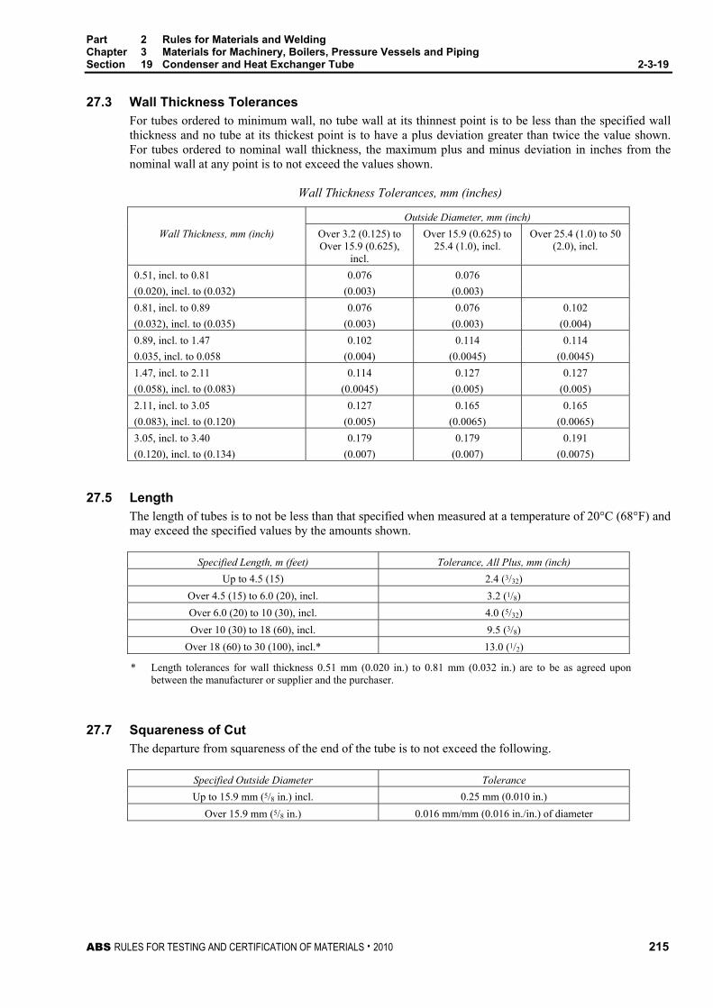
Part 2 Rules for Materials and Welding Chapter 3 Materials for Machinery, Boilers, Pressure Vessels and Piping Section 19 Condenser and Heat Exchanger Tube 2-3-19
ABS RULES FOR TESTING AND CERTIFICATION OF MATERIALS . 2010 215
27.3 Wall Thickness Tolerances For tubes ordered to minimum wall, no tube wall at its thinnest point is to be less than the specified wall thickness and no tube at its thickest point is to have a plus deviation greater than twice the value shown. For tubes ordered to nominal wall thickness, the maximum plus and minus deviation in inches from the nominal wall at any point is to not exceed the values shown.
Wall Thickness Tolerances, mm (inches)
Outside Diameter, mm (inch) Wall Thickness, mm (inch) Over 3.2 (0.125) to
Over 15.9 (0.625), incl.
Over 15.9 (0.625) to 25.4 (1.0), incl.
Over 25.4 (1.0) to 50 (2.0), incl.
0.51, incl. to 0.81 0.076 0.076 (0.020), incl. to (0.032) (0.003) (0.003) 0.81, incl. to 0.89 0.076 0.076 0.102 (0.032), incl. to (0.035) (0.003) (0.003) (0.004) 0.89, incl. to 1.47 0.102 0.114 0.114 0.035, incl. to 0.058 (0.004) (0.0045) (0.0045) 1.47, incl. to 2.11 0.114 0.127 0.127 (0.058), incl. to (0.083) (0.0045) (0.005) (0.005) 2.11, incl. to 3.05 0.127 0.165 0.165 (0.083), incl. to (0.120) (0.005) (0.0065) (0.0065) 3.05, incl. to 3.40 0.179 0.179 0.191 (0.120), incl. to (0.134) (0.007) (0.007) (0.0075)
27.5 Length The length of tubes is to not be less than that specified when measured at a temperature of 20°C (68°F) and may exceed the specified values by the amounts shown.
Specified Length, m (feet) Tolerance, All Plus, mm (inch) Up to 4.5 (15) 2.4 (3/32)
Over 4.5 (15) to 6.0 (20), incl. 3.2 (1/8) Over 6.0 (20) to 10 (30), incl. 4.0 (5/32) Over 10 (30) to 18 (60), incl. 9.5 (3/8)
Over 18 (60) to 30 (100), incl.* 13.0 (1/2)
* Length tolerances for wall thickness 0.51 mm (0.020 in.) to 0.81 mm (0.032 in.) are to be as agreed upon between the manufacturer or supplier and the purchaser.
27.7 Squareness of Cut The departure from squareness of the end of the tube is to not exceed the following.
Specified Outside Diameter Tolerance Up to 15.9 mm (5/8 in.) incl. 0.25 mm (0.010 in.)
Over 15.9 mm (5/8 in.) 0.016 mm/mm (0.016 in./in.) of diameter

Part 2 Rules for Materials and Welding Chapter 3 Materials for Machinery, Boilers, Pressure Vessels and Piping Section 19 Condenser and Heat Exchanger Tube 2-3-19
216 ABS RULES FOR TESTING AND CERTIFICATION OF MATERIALS . 2010
TABLE 1 Chemical Composition for Copper Nickel Pipe and Tube (1998)
Element
Grade CNA Grade CN1 Grade CN3
Grade CNB Grade CN2 Grade CN4
Copper Remainder Remainder Nickel + Cobalt 9.0 to 11.0 29.0 to 33.0 Iron 1.0 to 1.8 0.40 to 1.0 Managnese 1.0 1.0 Zinc 0.50 0.50 Lead 0.02 0.02 Carbon 0.05 0.05 Sulfur 0.02 0.02 Phosphorus 0.02 0.02
Single values are maximum
TABLE 2 Tensile Properties for Seamless Copper Nickel Pipe and Tube (1998)
Grade
Temper Designation
Tensile Strength, min. N/mm2 (kgf/mm2, ksi)
Yield Strength, min. N/mm2 (kgf/mm2, ksi)
Elongation, min. percent
CNA 061 275 (28,40) 105 (11,15) — CNA H55 310 (32,45) 240 (25,35) — CNB 061 360 (36,52) 125 (13,18) — CNB HR50 495 (51,72) 345 (35,50) 12*; 15**
Notes: * For wall thickness 1.21 mm (0.048 in.) and less.
** For wall thickness over 1.21 mm (0.048 in.).

ABS RULES FOR TESTING AND CERTIFICATION OF MATERIALS . 2010 217
P A R T S e c t i o n 2 0 : C o p p e r - N i c k e l T u b e a n d P i p e
2 C H A P T E R 3 Materials for Machinery, Boilers, Pressure
Vessels, and Piping
S E C T I O N 20 Copper-Nickel Tube and Pipe (1998)
Note: In substantial agreement with ASTM B466 and B467.
1 Scope This specification covers four grades of seamless and welded copper-nickel tube and pipe designated CN1, CN2, CN3 and CN4.
3 General
3.1 Grades CN1 and CN2 Grades CN1 and CN2 cover seamless copper-nickel tube and pipe intended for use in general engineering applications requiring seawater corrosion resistance. Tube and pipe ordered under these grades are considered suitable for welding, and suitable for forming operations involving bending, flaring and flanging. Tube is to be ordered to outer diameter and wall thickness specified by the purchaser and approved for the application.
3.3 Grades CN3 and CN4 Grades CN3 and CN4 cover welded copper-nickel pipe intended for use in general engineering applications requiring seawater corrosion resistance. Pipe ordered under these grades are considered suitable for welding, and suitable for forming operations involving bending, flaring and flanging.
3.5 ASTM Designation These grades are in substantial agreement with ASTM as follows:
ABS Grade ASTM Designation CN1 B466, UNS C70600 CN2 B466, UNS C71500 CN3 B467, UNS C70600 CN4 B467, UNS C71500
5 Process of Manufacture The material is to be produced by either hot or cold working operations, or both. The tubing is to be finished, unless otherwise specified, by such cold working or annealing or heat treatment as may be necessary to meet the properties for either annealed or light drawn material. The light drawn properties apply only to grades CN1 and CN3.
5.1 Grades CN1 and CN2 Grade CN1 may be supplied in either annealed (O60) or light drawn (H55) tempers. Grade CN2 may be supplied in only annealed (O60) temper.

Part 2 Rules for Materials and Welding Chapter 3 Materials for Machinery, Boilers, Pressure Vessels and Piping Section 20 Copper Nickel Tube and Pipe 2-3-20
218 ABS RULES FOR TESTING AND CERTIFICATION OF MATERIALS . 2010
5.3 Grades CN3 and CN4 Grade CN3 may be supplied in either the welded from annealed skelp temper (WM50), or the welded and fully finished as annealed temper (WO61). Grade CN4 may be supplied in the welded and fully finished as annealed temper (WO61). The internal and external flash is to be removed by scarfing and there is to be no crevice in the weld seam visible to the unaided eye.
7 Marking Identification markings are to be legibly stenciled, or suitably marked on each length of tubular, except that in the case of small-diameter tubular which is bundled, the required markings are to be placed on a tag securely attached to the bundle. The markings are to be arranged and are to include the following information:
• Name or brand of the manufacturer
• ABS Grade or ASTM Designation and Grade
• Temper number
• Diameter
• Wall thickness or Pipe Schedule
• Test Pressure or the letters NDET
• ABS markings by the Surveyor
9 Chemical Composition
9.1 Chemical Requirements The material is to conform to the chemical requirements specified in 2-3-19/Table 1.
9.3 Chemical Analysis Sampling Samples may be taken at the time the metal is cast or may be taken from semi-furnished product, or from finished product in accordance with sampling in 2-3-20/21.
11 Tension Test
11.1 Tension Test Specimens Tensile test specimens are to be a full section of the tube. For larger sizes, tension test specimens are to consist of longitudinal strips cut from the tube in accordance with ASTM E8, for Tension Testing of Metallic Materials.
11.3 Seamless Tensile Properties Seamless material is to conform to the applicable requirements as to tensile properties shown.
Temper Number
Temper
Grade
Tensile Strength, min. N/mm2 (kgf/mm2, ksi)
Yield Strength, min. N/mm2 (kgf/mm2, ksi)
060 Soft anneal CN1 260 (27, 38) 90 (9, 13) CN2 360 (37, 52) 125 (13, 18)
H55 Light Drawn CN1 310 (32, 45) 240 (25, 35)
11.5 Welded (WO61) Tensile Properties Welded and fully finished pipe furnished in the annealed temper (WO61) is to conform to the applicable requirements as to the tensile properties shown.

Part 2 Rules for Materials and Welding Chapter 3 Materials for Machinery, Boilers, Pressure Vessels and Piping Section 20 Copper Nickel Tube and Pipe 2-3-20
ABS RULES FOR TESTING AND CERTIFICATION OF MATERIALS . 2010 219
Grade
Outside Diameter, mm (inch)
Tensile Strength min. N/mm2 (kgf/mm2, ksi)
Yield Strength, min. N/mm2 (kgf/mm2, ksi)
Elongation percent
CN3 Up to 114 (4.5), incl. 275 (28, 40) 105 (11, 15) 25.0 over 114 (4.5) 260 (27, 38) 90 (9, 13) 25.0
CN4 Up to 114 (4.5), incl. 345 (35, 50) 140 (14, 20) 30.0 over 114 (4.5) 310 (32, 45) 105 (11, 15) 30.0
11.7 Welded (WO50) Tensile Properties As-welded pipe fabricated from annealed strip (WO50) is to conform to the applicable requirements as to the tensile properties shown.
Grade
Outside Diameter, mm (inch)
Tensile Strength, min. N/mm2 (kgf/mm2, ksi)
Yield Strength, min. N/mm2 (kgf/mm2, ksi)
CN3 up to 114 (4.5), incl. 310 (32, 45) 205 (21, 30)
13 Expansion Test Note: This test is required for tubes manufactured in the annealed temper.
13.1 Grades CN1 and CN2 Annealed specimens selected for testing in accordance with ASTM B153, for Expansion (Pin Test) of Copper and Copper-Alloy Pipe and Tubing, are to withstand an expansion of the outside diameter to 30 percent. The expanded specimen is to show no cracking or rupture visible to the unaided eye.
13.3 Grades CN3 and CN4 Annealed specimens selected for testing in accordance with ASTM B153, for Expansion (Pin Test) of Copper and Copper-Alloy Pipe and Tubing, are to withstand an expansion of the outside diameter to 30 percent. As welded specimens are to withstand an expansion of the outside diameter to 20 percent when similarly tested. The expanded specimen is to show no cracking or rupture visible to the unaided eye.
15 Flattening Test
As an alternate to the expansion test for seamless material over 100 mm (4 in.) in diameter and in the annealed condition, a flattening test may be carried out. This specimen selected for testing is to be at least 450 mm (18 in.) in length, and is to be flattened so that a gauge set at three times the wall thickness will pass over the tube freely throughout the flattened part. The tube so tested is to develop no cracks or defects visible to the unaided eye as a result of this test. In making the flattening test, the specimens are to be slowly flattened by one stroke of the press. Specimens not initially in the annealed temper (O60) are to be annealed prior to flattening.
17 Nondestructive Examination
17.1 Nondestructive Electric Test (NDET) All tubes are to be eddy-current tested in accordance with ASTM E243, for Electromagnetic (Eddy-Current) Examination of Copper and Copper-Alloy Tubes or, alternatively, when specified, may be hydrostatically tested in accordance with 2-3-19/19. A calibration reference standard is to be made from a length tube of the same type, wall thickness and outside diameter as that to be tested. The standard is to have transverse notches of depth that when rounded to 0.25 mm (0.001 in.) represents 22 percent of the wall thickness. The notch depth tolerance is to be 0.013 mm (0.0005 in.). Tubulars producing a signal equal to or greater than the calibration defect are to be rejected.
17.3 Radiographic Examination When specified, the welds of Grades CN3 and CN4 are to be examined by radiography.
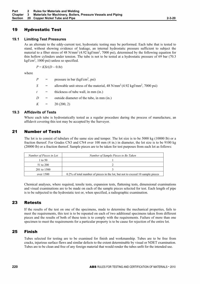
Part 2 Rules for Materials and Welding Chapter 3 Materials for Machinery, Boilers, Pressure Vessels and Piping Section 20 Copper Nickel Tube and Pipe 2-3-20
220 ABS RULES FOR TESTING AND CERTIFICATION OF MATERIALS . 2010
19 Hydrostatic Test
19.1 Limiting Test Pressures As an alternate to the eddy-current test, hydrostatic testing may be performed. Each tube that is tested to stand, without showing evidence of leakage, an internal hydrostatic pressure sufficient to subject the material to a fiber stress of 48 N/mm2 (4.92 kgf/mm2, 7000 psi), determined by the following equation for thin hollow cylinders under tension. The tube is not to be tested at a hydrostatic pressure of 69 bar (70.3 kgf/cm2, 1000 psi) unless so specified.
P = KSt/(D − 0.8t)
where
P = pressure in bar (kgf/cm2, psi)
S = allowable unit stress of the material, 48 N/mm2 (4.92 kgf/mm2, 7000 psi)
t = thickness of tube wall, in mm (in.)
D = outside diameter of the tube, in mm (in.)
K = 20 (200, 2)
19.3 Affidavits of Tests Where each tube is hydrostatically tested as a regular procedure during the process of manufacture, an affidavit covering this test may be accepted by the Surveyor.
21 Number of Tests The lot is to consist of tubulars of the same size and temper. The lot size is to be 5000 kg (10000 lb) or a fraction thereof. For Grades CN3 and CN4 over 100 mm (4 in.) in diameter, the lot size is to be 9100 kg (20000 lb) or a fraction thereof. Sample pieces are to be taken for test purposes from each lot as follows:
Number of Pieces in Lot Number of Sample Pieces to Be Taken 1 to 50 1
51 to 200 2 201 to 1500 3 over 1500 0.2% of total number of pieces in the lot, but not to exceed 10 sample pieces
Chemical analyses, where required, tensile tests, expansion tests, flattening tests, dimensional examinations and visual examinations are to be made on each of the sample pieces selected for test. Each length of pipe is to be subjected to the hydrostatic test or, when specified, a radiographic examination.
23 Retests If the results of the test on one of the specimens, made to determine the mechanical properties, fails to meet the requirements, this test is to be repeated on each of two additional specimens taken from different pieces and the results of both of these tests is to comply with the requirements. Failure of more than one specimen to meet the requirements for a particular property is to be cause for rejection of the entire lot.
25 Finish Tubes selected for testing are to be examined for finish and workmanship. Tubes are to be free from cracks, injurious surface flaws and similar defects to the extent determinable by visual or NDET examination. Tubes are to be clean and free of any foreign material that would render the tubes unfit for the intended use.

Part 2 Rules for Materials and Welding Chapter 3 Materials for Machinery, Boilers, Pressure Vessels and Piping Section 20 Copper Nickel Tube and Pipe 2-3-20
ABS RULES FOR TESTING AND CERTIFICATION OF MATERIALS . 2010 221
27 Dimensions and Tolerances Each sample selected for testing is to be examined for dimensions and tolerances.
27.1 Diameter The tubular outside diameter is to not vary from the specified values by more than the amounts shown. When all minus diameter tolerances or all plus diameter tolerances are specified, the tolerances shown may be doubled.
Average Diameter Specified Diameter
mm (inch) Tolerance,
Plus and Minus, mm (inch) Up to 15.9 (5/8), incl. 0.064 (0.0025)
Over 15.9 (5/8) to 25.4 (1.0), incl. 0.076 (0.003)
Over 25.4 (1.0) to 50 (2.0), incl. 0.102 (0.004) Over 50 (2.0) to 76 (3.0), incl. 0.127 (0.005) Over 76 (3.0) to 100 (4.0) incl. 0.152 (0.006) Over 100 (4.0) to 125 (5.0), incl. 0.203 (0.008) Over 125 (5.0) to 150 (6.0), incl. 0.229 (0.009) Over 150 (6.0) to 200 (8.0), incl. 0.254 (0.010) Over 200 (8.0) to 255 (10.0), incl. 0.330 (0.013) Over 255 (10.0) to 305 (12.0), incl. 0.381 (0.015) Over 305 (12.0) 0.5%
27.3 Roundness The difference between the major diameter and the minor diameter as determined at any one cross section is not the following.
Roundness Grade t/D (2) Tolerance Percent (3)
CN1 (1) and CN2 (1) 0.01 to 0.03, incl. 1.5 Over 0.03 to 0.05, incl. 1.0 Over 0.05 to 0.10, incl. 0.8* Over 0.10 0.7*
CN3 and CN4 All ratios 3.0
1 Drawn, unannealed straight lengths, wall thickness not less than 0.41 mm (0.016 in.)
2 Ration of wall thickness to outside diameter
3 Percent of outside diameter, to nearest 0.025 mm (0.001 in.)
* Or 0.051 mm (0.002 in.) whichever is greater
27.5 Wall Thickness Tolerances The permissible variations in wall thickness for all tubulars are based upon the ordered thickness and are to conform to that given in the applicable ASTM designation for acceptance.
27.7 Length The length of tubulars is to not be less than that specified when measured at a temperature of 20°C (68°F) and may exceed specified values by the amounts shown. The tolerance for stock lengths and for specific lengths with ends is 25.4 mm (1.0 in.).

Part 2 Rules for Materials and Welding Chapter 3 Materials for Machinery, Boilers, Pressure Vessels and Piping Section 20 Copper Nickel Tube and Pipe 2-3-20
222 ABS RULES FOR TESTING AND CERTIFICATION OF MATERIALS . 2010
Length Tolerance, mm (inch) Applicable Only to Full-Length Pieces
Grades CN1 and CN2
Specified Lengths ≤ 25 mm (1 in.) > 25.4 mm (1 in.) < 100 mm (4 in.) > 100 mm (4 in.)
Grades CN3 CN4
Up to 150 mm (6 in.), incl. 0.8 (1/32) 1.5 (1/16) — 1.5 (1/16) Over 150 to 600 mm (6 in. to 2 ft), incl.
1.5 (1/16) 2.5 (3/32) 3.0 (1/8) 2.5 (3/32)
Over 600 to 2000 mm (2 to 6 ft), incl.
2.5 (3/32) 3.0 (1/8) 6.0 (1/4) 3.0 (1/8)
Over 2000 to 4000 mm (6 to 14 ft), incl.
6.0 (1/4) 6.0 (1/4) 6.0 (1/4) 6.0 (1/4)
Over 4000 mm (14 ft) 12.0 (1/2) 12.0 (1/2) 12.0 (1/2) 12.0 (1/2)
27.9 Squareness of Cut The departure from squareness of the end of the tube is to not exceed the following:
Specified Outside Diameter Tolerance Up to 15.9 mm (5/8 in.) incl. of CN1 and CN2 0.25 mm (0.010 in.)
All diameters of CN3 and CN4. 0.016 mm/mm (0.016 in./in.) of diameter
27.11 Straightness Tolerances For seamless tubulars of any drawn temper, 6.0 mm (0.25 in.) to 100 mm (3.5 in.) in outside diameter, inclusive, but not for redrawn, extruded or annealed tubulars, the straightness tolerances are as shown.
Maximum Curvature
Length, mm (feet) (Depth of Arc), mm (inch) Over 1000 to 2000 (3 to 6), incl. 5.0 (3/16) Over 2000 to 2500 (6 to 8), incl. 8.0 (5/16) Over 2500 to 3000 (8 to 10), incl. 12.0 (1/2)
For lengths greater than 3000 mm (10 ft), the maximum curvature is to not exceed 12.5 mm (1/2 in.) in any 3000 mm (10 ft) portion of the total length.

ABS RULES FOR TESTING AND CERTIFICATION OF MATERIALS . 2010 223
P A R T S e c t i o n 2 1 : M o n e l P i p e a n d T u b e
2 C H A P T E R 3 Materials for Machinery, Boilers, Pressure
Vessels, and Piping
S E C T I O N 21 Monel Pipe and Tube (1999)
1 Scope This specification covers four grades of seamless and welded nickel-copper (Monel) pipe and tube, designated M1, M2, M3, and M4.
3 General
3.1 Grades M1 and M2 Grades M1 and M2 cover cold-worked, seamless nickel-copper pipe and pipe intended for use in general engineering applications requiring superior seawater corrosion resistance. Pipe and tube ordered under these grades are considered suitable for welding, and suitable for forming operations involving bending, flaring and flanging. Pipe is to be ordered to ANSI B36.19. Tube is to be ordered to an outer diameter and a nominal or minimum wall thickness specified by the purchaser and approved for the application.
3.3 Grades M3 and M4 Grades M3 and M4 cover welded, cold-worked nickel-copper pipe and pipe intended for use in general engineering applications requiring superior seawater corrosion resistance. Pipe and tube ordered under these grades are considered suitable for welding, and suitable for forming operations involving bending, flaring and flanging. Pipe is to be ordered to ANSI B36.19. Tube is to be ordered to an outer diameter and a nominal or minimum wall thickness specified by the purchaser and approved for the application.
3.5 ASTM Designation The grades are in substantial agreement with ASTM, as follows:
ABS Grade Heat Treatment ASTM Designation Product Form M1 Annealed B165, UNS N04400 Seamless Pipe and Tube M2 Stress Relieved B165, UNS N04400 Seamless Pipe and Tube M3 Annealed B730, UNS N04400 Welded Pipe and Tube M4 Stress Relieved B730, UNS N04400 Welded Pipe and Tube
5 Process of Manufacture
5.1 Grades M1 and M2 These grades are to be finished by cold-working in order to assure that acceptable corrosion resistance in the weld area and base metal will be developed during heat treatment. These grades of pipe and tube are to be supplied in the annealed, Grade M1 or stress-relieved, Grade M2 condition.

Part 2 Rules for Materials and Welding Chapter 3 Materials for Machinery, Boilers, Pressure Vessels and Piping Section 21 Monel Pipe and Tube 2-3-21
224 ABS RULES FOR TESTING AND CERTIFICATION OF MATERIALS . 2010
5.3 Grades M3 and M4 These grades are to be made from flat-rolled material by an automatic welding process with no addition of filler metal. After welding but before heat treatment, the pipe and tube are to be cold worked in order to assure that acceptable corrosion resistance in the weld area and base metal will be developed during heat treatment. Heat treatment is to consist of annealing, as Grade M3, or stress-relieving, as Grade M4. Welded pipe and tube are to be furnished with a scale-free finish. When bright annealing is used, descaling is not necessary.
7 Marking Identification markings are to be legibly stenciled, or marked on each length of pipe and tube. The marking fluid is not to be harmful to the pipe and tube and is not to rub off or smear in normal handling. The fluid is not to be affected by solvents used in subsequent cleaning and preservation operations, but is to be readily removed by hot alkaline solution. In the case of small-diameter tube or pipe with an outside diameter less than 19.0 mm (3/4 in.) which is bundled or boxed, the required markings are to be placed on a tag securely attached to the bundle or box, or on the box. The markings are to be arranged and are to include the following information:
• Name or brand of the manufacturer
• ABS Grade or ASTM Specification and Grade
• UNS Alloy Number
• Heat number or manufacturer’s number by which the heat can be identified
• Temper designation
• Tube diameter/NPS Designation
• Wall thickness (specify minimum or nominal)/NPS schedule
• Test pressure
• NDET if so tested
• ABS markings by Surveyor
9 Chemical Composition
9.1 Ladle Analysis The material is to conform to the chemical requirements specified below.
Element Content* , in percent Nickel 63.0 min. Copper 28.0 to 34.0 Iron 2.5 Manganese 2.0 Carbon 0.3 Silicon 0.5 Sulfur 0.024
* Single values are maxima, unless noted.
9.3 Chemical Composition – Check Analysis A check analysis may be made where so specified by the purchaser. The chemical composition thus determined is to conform to the requirements specified in 2-3-21/9.1, as modified by the product analysis tolerances of the relevant ASTM specification.

Part 2 Rules for Materials and Welding Chapter 3 Materials for Machinery, Boilers, Pressure Vessels and Piping Section 21 Monel Pipe and Tube 2-3-21
ABS RULES FOR TESTING AND CERTIFICATION OF MATERIALS . 2010 225
11 Tension Test
11.1 Tension Test Specimens Tensile test specimens are to be a full section of the pipe or tube. For larger sizes, tension test specimens are to consist of longitudinal strips cut from the pipe or tube in accordance with ASTM E8, for Tension Testing of Metallic Materials.
11.3 Annealed Tensile Properties Annealed pipe and tube, Grades M1 and M3, is to conform to the applicable requirements as to the tensile properties shown.
Outside Diameter in mm (in.)
Tensile Strength, min in N/mm2 (ksi)
0.2% Offset Yield Strength, min
in N/mm2 (ksi)
Percent Elongation, min,
in 50 mm (2 in.), or 4 D 127 mm (5 in.) and less 480 (70) 195 (28) 35 Over 127 mm (5 in.) 480 (70) 170 (25) 35
11.5 Stress Relieved Tensile Properties Stress relieved pipe and tube, Grades M2 and M4, is to conform to the applicable requirements as to the tensile properties shown.
Tensile Strength, min in N/mm2 (ksi)
0.2% Offset Yield Strength, min
in N/mm2 (ksi)
Percent Elongation, min,
in 50 mm (2 in.), or 4 D 585 (85) 380 (55) 15
13 Flattening Test Test specimens taken from samples of welded pipe and tube, Grades M3 or M4, having lengths not less than three times the specified outside diameter or 102 mm (4 in.), whichever is longer, are to be flattened under a load applied gradually at room temperature until the distance between the platens is not greater than five times the wall thickness. The weld is to be positioned 90 degrees from the direction of the applied flattening force. The flattened specimen is to show no cracking, breaks or ruptures on any surface when viewed with the unaided eye.
15 Flare Test Grades M1 and M3 pipe and tube 76 mm (3 in.) or less in specified outside diameter are to be subjected to a flare test. The flare test specimen is to be expanded by means of an expanding tool having an included angle of 60 degrees until the specified outside diameter has been increased by 30 percent. The expanded specimen is to show no cracking or rupture visible to the unaided eye.
17 Flange Test Test specimens taken from samples of welded pipe and tube, Grade M4, having lengths not less than three times the specified outside diameter or 102 mm (4 in.), whichever is longer, are to be flanged at a right angle to the tube until the width of the flange is not less than 15 percent the diameter of the tube. The flanged specimen is to show no cracking, breaks or ruptures on any surface when viewed with the unaided eye.
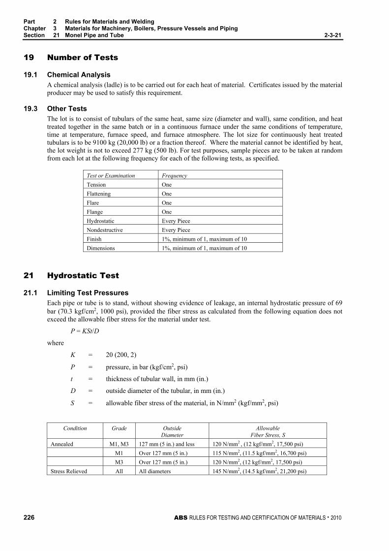
Part 2 Rules for Materials and Welding Chapter 3 Materials for Machinery, Boilers, Pressure Vessels and Piping Section 21 Monel Pipe and Tube 2-3-21
226 ABS RULES FOR TESTING AND CERTIFICATION OF MATERIALS . 2010
19 Number of Tests
19.1 Chemical Analysis A chemical analysis (ladle) is to be carried out for each heat of material. Certificates issued by the material producer may be used to satisfy this requirement.
19.3 Other Tests The lot is to consist of tubulars of the same heat, same size (diameter and wall), same condition, and heat treated together in the same batch or in a continuous furnace under the same conditions of temperature, time at temperature, furnace speed, and furnace atmosphere. The lot size for continuously heat treated tubulars is to be 9100 kg (20,000 lb) or a fraction thereof. Where the material cannot be identified by heat, the lot weight is not to exceed 277 kg (500 lb). For test purposes, sample pieces are to be taken at random from each lot at the following frequency for each of the following tests, as specified.
Test or Examination Frequency Tension One Flattening One Flare One Flange One Hydrostatic Every Piece Nondestructive Every Piece Finish 1%, minimum of 1, maximum of 10 Dimensions 1%, minimum of 1, maximum of 10
21 Hydrostatic Test
21.1 Limiting Test Pressures Each pipe or tube is to stand, without showing evidence of leakage, an internal hydrostatic pressure of 69 bar (70.3 kgf/cm2, 1000 psi), provided the fiber stress as calculated from the following equation does not exceed the allowable fiber stress for the material under test.
P = KSt/D
where
K = 20 (200, 2)
P = pressure, in bar (kgf/cm2, psi)
t = thickness of tubular wall, in mm (in.)
D = outside diameter of the tubular, in mm (in.)
S = allowable fiber stress of the material, in N/mm2 (kgf/mm2, psi)
Condition Grade Outside Diameter
Allowable Fiber Stress, S
Annealed M1, M3 127 mm (5 in.) and less 120 N/mm2 , (12 kgf/mm2, 17,500 psi) M1 Over 127 mm (5 in.) 115 N/mm2, (11.5 kgf/mm2, 16,700 psi) M3 Over 127 mm (5 in.) 120 N/mm2, (12 kgf/mm2, 17,500 psi) Stress Relieved All All diameters 145 N/mm2, (14.5 kgf/mm2, 21,200 psi)

Part 2 Rules for Materials and Welding Chapter 3 Materials for Machinery, Boilers, Pressure Vessels and Piping Section 21 Monel Pipe and Tube 2-3-21
ABS RULES FOR TESTING AND CERTIFICATION OF MATERIALS . 2010 227
21.3 Exceeding Limiting Test Pressures When so agreed, the hydrostatic test pressure may exceed the limits stated in Section 2-3-3 to a maximum of 1.5 times the allowable fiber stress values shown above.
21.5 Affidavits of Tests Where each tube is hydrostatically tested as a regular procedure during process of manufacture, an affidavit covering this test may be accepted by the Surveyor.
23 Nondestructive Electric Test (NDET)
23.1 General When specified by the purchaser, welded pipe or tube is to be tested in accordance with ASTM E213, for Ultrasonic Inspection of Metal Pipe and Tubing, ASTM E571, for Electromagnetic (Eddy-current) Examination of Nickel and Nickel Alloy Tubular Products, or other approved standard. It is the intent of these tests to reject tubes containing defects, and the Surveyor is to be satisfied that the nondestructive testing procedures are used in a satisfactory manner.
23.3 Ultrasonic Calibration Standards Longitudinal notches machined on the outside surface and on the inside surface are to be used. The notch depth is to not exceed 12.5% of the specified wall thickness or 0.004 inch (0.10 mm), whichever is greater. The notch is to be placed in the weld if visible.
23.5 Eddy-Current Calibration Standards In order to accommodate the various types of nondestructive electrical testing equipment and techniques in use, and manufacturing practices employed, any one of the following calibration standards may be used at the option of the producer to establish a minimum sensitivity level for rejection. The holes and notches are to be placed in the weld, if visible.
23.5.1 Drilled Hole A hole not larger than 0.79 mm (0.031 in.) in diameter is to be drilled radially and completely through tube wall, care being taken to avoid distortion of the tube while drilling.
23.5.2 Transverse Tangential Notch Using a round file or tool with a 6.4 mm (0.25 in.) diameter, a notch is to be filed or milled tangential to the surface and transverse to the longitudinal axis of the tube. Said notch is to have a depth not exceeding 12.5% of the nominal wall thickness of the tube or 0.10 mm (0.004 in.), whichever is greater.
23.5.3 Longitudinal Notch A notch 0.79 mm. (0.031 in.) or less in width is to be machined in a radial plane parallel to the tube axis on the outside surface of the tube, to a depth not exceeding 12.5% of the nominal wall thickness of the tube or 0.10 mm (0.004 in.), whichever is greater. The length of the notch is to be compatible with the testing method.
23.7 Rejection Tubulars producing a signal equal to or greater than the calibration defect are to be subject to rejection.
23.9 Affidavits When each tubular is subjected to an approved nondestructive electrical test as a regular procedure during the process of manufacture, an affidavit covering this test may be accepted by the Surveyor.

Part 2 Rules for Materials and Welding Chapter 3 Materials for Machinery, Boilers, Pressure Vessels and Piping Section 21 Monel Pipe and Tube 2-3-21
228 ABS RULES FOR TESTING AND CERTIFICATION OF MATERIALS . 2010
25 Retests If the results of the test on one of the specimens made to determine the mechanical properties, fails to meet the requirements, this test is to be repeated on each of two additional specimens taken from different pieces from same group or lot, and the results of both of these tests are to comply with the requirements. Failure of more than one specimen to meet the requirements for a particular property is to be cause for rejection of the entire lot.
27 Finish Pipe or tube selected for testing is to be examined for finish and workmanship. The samples examined are to be free from cracks, injurious surface flaws and similar defects to the extent determinable by visual or NDET examination. All pipe or tube is to be clean and free of any foreign material that would render the tubulars unfit for the intended use.
29 Dimensions and Tolerances Pipe or tube selected for testing is to be examined and measured for dimensions and tolerances.
29.1 Diameter The outside diameter of pipe and tube, including ovality, is not to exceed the following permissible variations.
Nominal Outside Diameter in mm (in.)
Over and Under Tolerances in mm (in.)
Over 3.2 (0.125) to 16 (5/8), excl. 0.13 (0.005) 16 (5/8) to 38 (11/2), incl. 0.19 (0.0075) Over 38 (11/2) to 76 (3), incl. 0.25 (0.010) Over 76 (3) to 114 (41/2), incl. 0.38 (0.015) Over 114 (41/2) to 152 (6), incl. 0.51(0.020) Over 152 (6) to 168 (65/8), incl. 0.64 (0.025) Over 168 (65/8) to 219 (85/8), incl. 0.79 (0.031)
For pipe and tube having a nominal wall thickness of 3% or less of the nominal outside diameter, the mean outside diameter is to conform to the above permissible variations and individual measurements (including ovality) are to conform to the over and under values, with the values increased by 0.5% of the nominal outside diameter. For pipe and tube over 114 mm (41/2 in.) in outside diameter with a nominal wall thickness greater than 3% of the nominal outside diameter, the mean outside diameter is to conform to the above permissible variations, and individual measurements are not to exceed twice the above permissible variations.
29.3 Wall Thickness – Seamless The wall thickness of seamless pipe and tube is not to exceed the permissible variations shown below for the type (nominal or minimum) of specified wall thickness ordered.
Variation in Thickness of Specified Nominal Wall
Variation in Thickness of Specified Minimum Wall
Nominal Outside Diameter in mm (in.)
Over in percent
Under in percent
Over in percent
Under in percent
Over 10 (0.400) to 16 (5/8), excl. 15.0 15.0 30 0 16 (5/8) to 38 (11/2), incl. 10.0 10.0 22 0 Over 38 (11/2) to 76 (3), incl. 10.0 10.0 22 0 Over 76 (3) to 114 (41/2), incl. 10.0 10.0 22 0 Over 114 (41/2) to 152 (6), incl. 12.5 12.5 28 0 Over 152 (6) to 168 (65/8), incl. 12.5 12.5 28 0 Over 168 (65/8) to 219 (85/8), incl. 12.5 12.5 28 0

Part 2 Rules for Materials and Welding Chapter 3 Materials for Machinery, Boilers, Pressure Vessels and Piping Section 21 Monel Pipe and Tube 2-3-21
ABS RULES FOR TESTING AND CERTIFICATION OF MATERIALS . 2010 229
29.5 Wall Thickness – Welded The wall thickness of welded pipe and tube is not to exceed the permissible variations shown below for the type (nominal or minimum) of specified wall thickness ordered.
Variation in Thickness of Specified Nominal Wall
Variation in Thickness of Specified Minimum Wall
Nominal Outside Diameter in mm (in.)
Over in percent
Under in percent
Over in percent
Under in percent
Over 3.2 (0.125) to 16 (5/8), excl. 15.0 15.0 30 0 16 (5/8) to 38 (11/2), incl. 12.5 12.5 28 0 Over 38 (11/2) to 76 (3), incl. 12.5 12.5 28 0 Over 76 (3) to 114 (41/2), incl. 12.5 12.5 28 0 Over 114 (41/2) to 152 (6), incl. 12.5 12.5 28 0 Over 152 (6) to 168 (65/8), incl. 12.5 12.5 28 0 Over 168 (65/8) to 219 (85/8), incl. 12.5 12.5 28 0
29.7 Cut Ends Ends are to be plain or cut and deburred unless otherwise specified.
29.9 Straightness Pipe and tube are to be reasonably straight and free of bends and kinks.
230 ABS RULES FOR WELDING AND FABRICATION . 2010
P A R T C h a p t e r 4 : W e l d i n g a n d F a b r i c a t i o n
2 Rules for Welding and Fabrication
C H A P T E R 4 Welding and Fabrication
CONTENTS SECTION 1 Hull Construction ............................................................................... 235
1 General ...........................................................................................235 1.1 Hull Welding ................................................................................235 1.3 Plans and Specifications..............................................................235 1.5 Workmanship and Supervision ....................................................235 1.7 Welding Procedures ....................................................................235 1.9 TMCP Plates – Note to Users......................................................235
3 Preparation for Welding ..................................................................236 3.1 Edge Preparation and Fitting .......................................................236 3.3 Alignment.....................................................................................236 3.5 Cleanliness ..................................................................................236 3.7 Tack Welds..................................................................................236 3.9 Run-on and Run-off Tabs ............................................................236 3.11 Stud Welding ...............................................................................236 3.13 Forming .......................................................................................237
5 Production Welding.........................................................................237 5.1 Environment ................................................................................237 5.3 Sequence ....................................................................................237 5.5 Preheat ........................................................................................237 5.7 Low-hydrogen Electrodes or Welding Processes ........................237 5.9 Back Gouging ..............................................................................238 5.11 Peening .......................................................................................238 5.12 Weld Profiling ..............................................................................238 5.13 Fairing and Flame Shrinking........................................................238 5.15 Surface Appearance and Weld Soundness .................................238 5.17 Inspection of Welds .....................................................................238 5.19 Repair Welding ............................................................................239 5.21 Fillet Weld Ends...........................................................................239
7 Butt Welds.......................................................................................239 7.1 Manual Welding Using Covered Electrodes ................................239 7.3 Submerged-arc Welding ..............................................................239 7.5 Gas Metal-arc and Flux Cored-arc Welding.................................240 7.7 Electroslag and Electrogas Welding ............................................240 7.9 Special Welding Processes and Techniques...............................240
ABS RULES FOR WELDING AND FABRICATION . 2010 231
SECTION 2 Boilers, Unfired Pressure Vessels, Piping & Engineering Structures ........................................................................................... 241 1 General Considerations ..................................................................241
1.1 Fabrication................................................................................... 241 1.3 Welding Approval ........................................................................ 241 1.5 Grouping of Welded Structures ................................................... 241 1.7 Weld Repairs to Ductile (Nodular) Iron........................................ 242
3 Plans and Specifications.................................................................242 3.1 Details ......................................................................................... 242 3.3 Base Materials.............................................................................242
5 Workmanship and Supervision .......................................................243 5.1 Construction ................................................................................ 243 5.3 Joint Tolerance............................................................................ 243 5.5 Surfaces of Parts......................................................................... 243 5.7 Out of Roundness ....................................................................... 243
7 Details of Joints...............................................................................244 7.1 Dimensions and Shape ............................................................... 244 7.3 Double-welded Butt Joints........................................................... 244 7.5 Single-welded Butt Joints ............................................................ 244 7.7 Joint Finish ..................................................................................244 7.9 Lap Joints ....................................................................................244 7.11 Head to Shell Attachments .......................................................... 244 7.13 Bending Stresses in Welds.......................................................... 244 7.15 Connections ................................................................................244 7.17 Nozzles........................................................................................ 245 7.19 Limitations ................................................................................... 245
9 Forms of Welded Joints Required ..................................................245 9.1 Boilers and Group I Pressure Vessels......................................... 245 9.3 Group II Pressure Vessels........................................................... 246 9.5 Group I Pipe Welded Joints......................................................... 246 9.7 Group II Pipe Welded Joints........................................................ 247 9.9 Low-temperature Piping Systems [Below -18°C (0°F)]................ 247 9.11 Engineering Structures................................................................ 247
11 Preheat............................................................................................247 11.1 Boilers, Pressure Vessels, and Group I Piping............................ 247 11.3 Group I Pipe Connections ........................................................... 248
13 General Requirements for Postweld Heat Treatment.....................248 13.1 General........................................................................................248 13.3 Heat-treatment Determination ..................................................... 248
15 Fusion-welded Boilers.....................................................................248 15.1 Postweld Heat Treatment ............................................................ 248 15.3 Lower Temperatures – Carbon and Carbon Molybdenum
Steels .......................................................................................... 249 15.5 Heat-treatment Exceptions for Fusion-welded Boilers – ABS
Plate Grades MA, MB, MC, MD, ME, MF, MG, K, L, M, N, Tube Grades D, F, G, H, J and Group I Piping Grades 1, 2, 3, 4, 5, 8, and 9 ................................................................... 249
15.7 Heat-treatment Exceptions for Fusion-welded Boilers – ABS Plate Grades H, I, J, Tube Grades K, L, M, and Group I Piping Grades 6 and 7................................................................. 249

232 ABS RULES FOR WELDING AND FABRICATION . 2010
15.9 Heat Treatment Exceptions for Fusion-welded Boilers – ABS Tube Grades N, O and Group I Pipe Grades 11 and 12..............250
15.11 Heat Treatment Exceptions for Fusion Welded Boilers – ABS Tube Grade P and Group I Pipe Grade 13 ...................................250
15.13 Other Materials ............................................................................251 15.15 Other Welded Connections..........................................................251 15.17 Welded Joints ..............................................................................251
17 Fusion-welded Pressure Vessels....................................................251 17.1 Postweld Heat Treatment ............................................................251 17.3 Heat-treatment Exceptions – ABS Plate Grades MA, MB, MC,
MD, ME, MF, MG, K, L, M, N and Tube Grades D, F, G, H, J .....252 17.5 Heat-treatment Exceptions – ABS Plate Grades H, I, J and
Tube Grades K, L, M ...................................................................252 17.7 Heat-treatment Exceptions – Attachments ..................................252 17.9 Other Materials ............................................................................252 17.11 Welded Connections....................................................................253
19 Pipe Welded Joints and Engineering Structures ............................253 19.1 Group I Pipe Welded Joints .........................................................253 19.3 Group II Pipe Welded Joints ........................................................253 19.5 Group I Engineering Structures ...................................................253 19.7 Group II Engineering Structures ..................................................253 19.9 Low-temperatures Piping Systems [Below -18°C (0°F)] ..............253
21 Postweld Heat-treatment Details ....................................................253 21.1 Boilers and Pressure Vessels......................................................253 21.3 Pipe Connections.........................................................................253 21.5 Other Steels.................................................................................253 21.7 Clad Pressure Vessels ................................................................253 21.9 Opening Connections ..................................................................254 21.11 Seal Welding ...............................................................................254
23 Radiography....................................................................................254 23.1 General........................................................................................254 23.3 Boilers..........................................................................................254 23.5 Other Pressure Vessels...............................................................255 23.7 Group I Pipe Connections............................................................255 23.9 Group II Pipe Connections...........................................................255 23.11 Low Temperature Piping Connections [Below -18°C (0°F)] .........255 23.13 Group I Engineering Structures ...................................................255 23.15 Group II Engineering Structures ..................................................255 23.17 Engine Bedplates.........................................................................256 23.19 Miscellaneous..............................................................................256
25 Hydrostatic Test ..............................................................................256 25.1 Boilers and Pressure Vessels......................................................256 25.3 Piping...........................................................................................256 25.5 Defects ........................................................................................256 25.7 Retest ..........................................................................................256
TABLE 1 Hydrostatic Testing of Piping ................................................256

ABS RULES FOR WELDING AND FABRICATION . 2010 233
FIGURE 1 Head to Shell Attachments ...................................................257 FIGURE 2 Types of Fusion-welded Construction Details ......................260
SECTION 3 Weld Tests .......................................................................................... 263
1 General ...........................................................................................263 1.1 Weld Groups ............................................................................... 263 1.3 Tests ........................................................................................... 263
3 Filler Metals.....................................................................................263 3.1 General........................................................................................263 3.3 Approval Basis ............................................................................ 263
5 Approval of Welding Procedures ....................................................264 5.1 Approved Filler Metals................................................................. 264 5.3 Surveyor’s Acceptance................................................................ 264 5.5 New Procedures and Methods .................................................... 264 5.7 Tests ........................................................................................... 264 5.9 Special Tests............................................................................... 264 5.11 Repair and Cladding of Stern Tube and Tail Shafts .................... 265
7 Workmanship Tests ........................................................................265 7.1 Hull Construction ......................................................................... 265 7.3 Boilers and Group I Pressure Vessels......................................... 265 7.5 Other Pressure Vessels............................................................... 266 7.7 Group I Pipe Connections ........................................................... 266 7.9 Group II Pipe Connections .......................................................... 266 7.11 Group I Engineering Structures ................................................... 266 7.13 Group II Engineering Structures .................................................. 266
9 Radiographic or Ultrasonic Inspection ............................................266 9.1 Hull Construction ......................................................................... 266 9.3 Boilers and Pressure Vessels...................................................... 266
11 Welders...........................................................................................267 11.1 General Requirements ................................................................ 267 11.3 Qualification Tests....................................................................... 267 11.5 Tests Nos. Q1, Q2, Q3, and Q4 .................................................. 267
TABLE 1 Welder Qualification Tests ....................................................268 FIGURE 1 Preparation of Test Plates and Pipes for Weld Tests
Nos. 1 and 2..........................................................................269 FIGURE 2 Typical Arrangement of Test Plates for Workmanship
Tests in Group B1 .................................................................271 FIGURE 3 Test No. 1 – Reduced-section Tension Test for Plate..........272 FIGURE 4 Test No. 1 – Reduced-section Tension Test for Pipe...........273 FIGURE 5 Test No. 2 – Guided Bend Test for Root Bend and Face
Bend (Plate or Pipe)..............................................................274 FIGURE 6 Test No. 2 – Guided Bend Test for Side Bend
(Plate or Pipe) .......................................................................274 FIGURE 7 Guided Bend Test Jig ...........................................................275 FIGURE 8 Test No. 3 – Fillet-weld Test .................................................276

234 ABS RULES FOR WELDING AND FABRICATION . 2010
FIGURE 9 Welder Qualification Test No. Q1 .........................................277 FIGURE 10 Welder Qualification Test No. Q2 .........................................278 FIGURE 11A Welder Qualification Test No. Q3 .........................................279 FIGURE 11B Welder Qualification Test No. Q3 – 6GR..............................280 FIGURE 11C Welder Qualification Test No. Q3R.......................................281 FIGURE 12 Welder Qualification Test No. Q4 .........................................282 FIGURE 13 Orientation and Location of Charpy V-notch Specimens
for Weld and Heat Affected Zone Properties ........................283 SECTION 4 Piping .................................................................................................. 284
1 General ...........................................................................................284 1.1 Application ...................................................................................284 1.3 Pipe Classes................................................................................284 1.5 Materials ......................................................................................284 1.7 Welding Filler Metals ...................................................................285
3 Welding Procedures and Welders ..................................................285 3.1 Welding Procedures ....................................................................285 3.3 Welders and Welding Operators..................................................285
5 Types of Welded Joints...................................................................285 5.1 Full Penetration Butt Joints..........................................................285 5.3 Square-groove Butt Joint .............................................................286 5.5 Fillet-welded Joints ......................................................................286 5.7 Flange Attachment Welds............................................................286 5.9 Branch Connections ....................................................................287 5.11 Tack Welding...............................................................................287 5.13 Brazing ........................................................................................287
7 Preheat............................................................................................287 9 Post-weld Heat Treatment ..............................................................287
9.1 Procedure ....................................................................................287 9.3 Requirement ................................................................................288
11 Nondestructive Examination ...........................................................288 11.1 Visual Examination ......................................................................288 11.3 Butt Weld Joints...........................................................................288 11.5 Fillet Weld Joints..........................................................................289
13 Weld Repair ....................................................................................289 15 Pipe Forming and Bending .............................................................289
15.1 Cold Forming ...............................................................................289 15.3 Hot Forming.................................................................................289
17 Additional Requirements for Low Temperature Piping [Below -10°C (14°F)] .......................................................................290 17.1 Application ...................................................................................290 17.3 Welding Procedure ......................................................................290 17.5 Pipe Joints ...................................................................................290 17.7 Post-weld Heat Treatment ...........................................................290 17.9 Nondestructive Examination ........................................................290
ABS RULES FOR WELDING AND FABRICATION . 2010 235
P A R T S e c t i o n 1 : H u l l C o n s t r u c t i o n
2 C H A P T E R 4 Welding and Fabrication
S E C T I O N 1 Hull Construction
1 General
1.1 Hull Welding Welding in hull construction is to comply with the requirements of this section, unless specially approved otherwise. It is recommended that appropriate permanent markings be applied to the side shell of welded vessels to indicate the location of bulkheads for reference. In all instances welding procedures and filler metals are to produce sound welds having strength and toughness comparable to the base material. For weld design, see Section 3-2-19.
1.3 Plans and Specifications The plans submitted are to clearly indicate the proposed extent of welding to be used in the principal parts of the structure. The welding process, filler metal and joint design are to be shown on the detail drawings or in separate specifications submitted for approval which should distinguish between manual and automatic welding. The shipbuilders are to prepare and file with the Surveyor a planned procedure to be followed in the erection and welding of the important structural members.
1.5 Workmanship and Supervision The Surveyor is to satisfy himself that all welders and welding operators to be employed in the construction of vessels to be classed are properly qualified and are experienced in the work proposed. The Surveyor is also to be satisfied as to the employment of a sufficient number of skilled supervisors to ensure a thorough supervision and control of all welding operations. Inspection of welds employing methods outlined in 2-4-1/5.17 is to be carried out to the satisfaction of the Surveyor.
1.7 Welding Procedures 1.7.1 General
Procedures for the welding of all joints are to be established before construction for the welding processes, types of electrodes, edge preparations, welding techniques, and positions proposed. See 2-4-3/5. Details of proposed welding procedures and sequences may be required to be submitted for review depending on the intended application.
1.7.2 Weld Metal Toughness – Criteria for ABS Grades of Steel (2009) For steels shown in 2-1-2/Table 4 and 2-1-3/Table 4 of these Rules, and 3-1-A3/Table 2 of the ABS Rules for Building and Classing Mobile Offshore Drilling Units, Approved filler metals appropriate to the grades shown in Part 2, Appendix 3 may be used.
1.7.3 Weld Metal Toughness – Criteria for Other Steels Weld metal is to exhibit Charpy V-notch toughness values at least equivalent to transverse base metal requirements (2/3 of the longitudinal base metal requirements).
1.9 TMCP Plates – Note to Users (1996) When considering thermo-mechanically controlled steels for further heating for forming or stress relieving, or for high heat input welding, the attention of the fabricator is drawn to the possible reduction in the mechanical properties. A procedure test using representative material is to be considered.

Part 2 Rules for Materials and Welding Chapter 4 Welding and Fabrication Section 1 Hull Construction 2-4-1
236 ABS RULES FOR WELDING AND FABRICATION . 2010
3 Preparation for Welding
3.1 Edge Preparation and Fitting The edge preparation is to be accurate and uniform and the parts to be welded are to be fitted in accordance with the approved joint detail. All means adopted for correcting improper fitting are to be to the satisfaction of the Surveyor. The Surveyor may accept a welding procedure for build up of each edge that does not exceed one half the thickness of the member or 12.5 mm (0.5 in.), whichever is the lesser. The Surveyor may accept edge build up in excess of the above, up to the full thickness of the member on a case-by-case basis, provided the Surveyor is notified of such cases before the members are welded together. Where plates to be joined differ in thickness and have an offset on either side of more than 3 mm (1/8 in.), a suitable transition taper is to be provided. For the transverse butts in bottom shell, sheer strake, and strength deck plating within the midship portion of the hull, and other joints which may be subject to comparatively high stresses, the transition taper length is to be not less than three times the offset. The transition may be formed by tapering the thicker member or by specifying a weld joint design which will provide the required transition.
3.3 Alignment Means are to be provided for maintaining the parts to be welded in correct position and alignment during the welding operation. In general, strong backs, or other appliances used for this purpose are to be so arranged as to allow for expansion and contraction during production welding. The removal of such items is to be carried out to the satisfaction of the Surveyor.
3.5 Cleanliness All surfaces to be welded are to be free from moisture, grease, loose mill scale, excessive rust or paint. Primer coatings of ordinary thickness, thin coatings of linseed oil, or equivalent coatings may be used, provided it is demonstrated that their use has no adverse effect in the production of satisfactory welds. Slag and scale are to be removed not only from the edges to be welded but also from each pass or layer before the deposition of subsequent passes or layers. Weld joints prepared by arc-air gouging may require additional preparation by grinding or chipping and wire brushing prior to welding to minimize the possibility of excessive carbon on the scarfed surfaces. Compliance with these cleanliness requirements is of prime importance in the welding of higher-strength steels, especially those which are quenched and tempered.
3.7 Tack Welds Tack welds of consistently good quality, made with the same grade of filler metal as intended for production welding and deposited in such a manner as not to interfere with the completion of the final weld, need not be removed, provided they are found upon examination to be thoroughly clean and free from cracks or other defects. Preheat may be necessary prior to tack welding when the materials to be joined are highly restrained. Special consideration is to be given to use the same preheat as specified in the welding procedure when tack welding higher-strength steels, particularly those materials which are quenched and tempered. These same precautions are to be followed when making any permanent welded markings.
3.9 Run-on and Run-off Tabs When used, run-on and run-off tabs are to be designed to minimize the possibility of high-stress concentrations and base-metal and weld-metal cracking.
3.11 Stud Welding The attachment of pins, hangers, studs, and other related items to ordinary and higher-strength hull structural steels or equivalent by stud welding may be approved at the discretion of the Surveyor. Stud welded attachment to quenched and tempered steel is to be specially approved. At the Surveyor’s discretion, trial stud welds may be tested to demonstrate that the base material in way of the stud welds is free from cracking and excessively high hardness. The use of stud welding for structural attachments is subject to special approval and may require special procedure tests appropriate to each application.

Part 2 Rules for Materials and Welding Chapter 4 Welding and Fabrication Section 1 Hull Construction 2-4-1
ABS RULES FOR WELDING AND FABRICATION . 2010 237
3.13 Forming Steel is not to be formed between the upper and lower critical temperatures; forming in the range between 205°C (400°F) and 425°C (800°F) should be avoided. If the forming temperature exceeds 650°C (1200°F) for as-rolled, controlled rolled, thermo-mechanical controlled rolled or normalized steels, or is not at least 28°C (50°F) lower than the tempering temperature for quenched and tempered steels, mechanical tests are to be made to assure that these temperatures have not adversely affected the mechanical properties of the steel. See 2-4-1/1.9.
For applications where toughness is of particular concern (such as Class III in 3-1-2/Table 2), when steel is formed below 650°C (1200°F) beyond 3% strain* on the outer fiber, supporting data is to be provided to the satisfaction of the Surveyor indicating that the impact properties meet minimum requirements after forming. After straining, specimens used in charpy impact tests are to be subjected to an artificial aging treatment of 288°C (550°F) for one (1) hour before testing. Rule steels of 2-1-2/Table 5 and 2-1-3/Table 5 or equivalent steels used for radius gunwales (in accordance with 3-1-2/Table 1) may be cold formed to a minimum radius of 15t without requiring stress relieving or other supporting data.
* Calculated on the basis of % strain = radiusouterthicknessplate65 ×
5 Production Welding
5.1 Environment Proper precautions are to be taken to insure that all welding is done under conditions where the welding site is protected against the deleterious effects of moisture, wind and severe cold.
5.3 Sequence Welding is to be planned to progress symmetrically so that shrinkage on both sides of the structure will be equalized. The ends of frames and stiffeners should be left unattached to the plating at the subassembly stage until connecting welds are made in the intersecting systems of plating, framing and stiffeners at the erection stage. Welds are not to be carried across an unwelded joint or beyond an unwelded joint which terminates at the joint being welded unless specially approved.
5.5 Preheat The use of preheat and interpass temperature control are to be considered when welding higher-strength steels, materials of thick cross-section or materials subject to high restraint. When welding is performed under high humidity conditions or when the temperature of steel is below 0°C (32°F), the base metal is to be preheated to at least 16°C (60°F) or temperature appropriate to the alloy and the thickness, whichever is higher. The control of interpass temperature is to be specially considered when welding quenched and tempered higher-strength steels. When preheat is used, the preheat and interpass temperatures are to be in accordance with the accepted welding procedure and to the satisfaction of the Surveyor. In all cases, preheat and interpass temperature control are to be sufficient to maintain dry surfaces and minimize the possibility of the formation of fractures.
5.7 Low-hydrogen Electrodes or Welding Processes 5.7.1 Welding of Ordinary and Higher Strength Steel
The use of low-hydrogen electrodes or welding processes is recommended for welding all higher-strength steel and may also be considered for ordinary-strength steel weldments subject to high restraint. When using low-hydrogen electrodes or processes, proper precautions are to be taken to ensure that the electrodes, fluxes and gases used for welding are clean and dry.

Part 2 Rules for Materials and Welding Chapter 4 Welding and Fabrication Section 1 Hull Construction 2-4-1
238 ABS RULES FOR WELDING AND FABRICATION . 2010
5.7.2 Welding of Quenched and Tempered Steels Unless approved otherwise, matching strength, low-hydrogen electrodes or welding processes are to be used for welding quenched and tempered steels and overmatching should be generally avoided. When welding quenched and tempered steels to other steels, the weld filler metal selection is to be based on the lower strength base material being joined and low hydrogen practice being comparable to that for the higher strength material. In all cases, filler metal strength is to be no less than that of the lowest strength member of the joint unless approved otherwise. The Surveyor is to be satisfied that the procedures for handling and baking filler metals and fluxes are commensurate with the low-hydrogen practices appropriate to the highest strength steel.
5.9 Back Gouging Except as permitted in 2-4-1/7.3, chipping, grinding, arc-air gouging or other suitable methods are to be employed at the root or underside of the weld to obtain sound metal before applying subsequent beads for all full-penetration welds. When arc-air gouging is employed, a selected technique is to be used so that carbon buildup and burning of the weld or base metal is minimized. Quenched and tempered steels are not to be flame gouged.
5.11 Peening (2010) Peening, when used to correct distortion, is to be effected immediately after depositing and cleaning each weld pass. The use of peening is not recommended for single-pass welds, the root or cover passes on multipass welds, or on the base metal at the edges of the weld except as provided in 2-4-1/5.12 to enhance fatigue life.
5.12 Weld Profiling (2010) For fatigue life enhancement, weld profiling may be carried out (e.g., in critical areas). Welds may be profiled using grinding, TIG dressing, or peening, at weld toes to the satisfaction of the attending Surveyor.
5.13 Fairing and Flame Shrinking Fairing by heating or flame shrinking and other methods of correcting distortion or defective workmanship in fabrication of main strength members within the midship portion of the vessel and other plating which may be subject to high stresses is to be carried out only with the express approval of the Surveyor. These corrective measures are to be kept to an absolute minimum when the higher-strength steels are involved, due to high local stresses and the possible degradation of the mechanical properties of the base material. See 2-4-1/1.9.
5.15 Surface Appearance and Weld Soundness 5.15.1 Surface Appearance
The surfaces of welds are to be visually inspected and are to be regular and uniform with a minimum amount of reinforcement and reasonably free from undercut and overlap. Welds and adjacent base metal are to be free from injurious arc strikes.
5.15.2 Weld Soundness Welds are to be sound, crack free throughout the weld cross section, and fused to the base material to the satisfaction of the attending Surveyor and should generally be considered on the basis of 2-4-1/1.5 “Workmanship and Supervision”, 2-4-1/1.7 “Welding Procedure Qualification”, and 2-4-1/5.17 “Nondestructive Inspection of Welds”.
5.17 Inspection of Welds Inspection of welded joints in important locations is to be carried out by an approved nondestructive test method such as radiographic, ultrasonic, magnetic-particle or dye-penetrant inspection. The Bureau’s separately issued Guide for Nondestructive Inspection of Hull Welds or an approved equivalent standard is to be used in evaluating radiographs and ultrasonic indications. Evaluation of radiographs and ultrasonic indications is one of the factors in assessing shipyard weld quality control. Radiographic or ultrasonic inspection, or both, is to be used when the overall soundness of the weld cross section is to be evaluated.

Part 2 Rules for Materials and Welding Chapter 4 Welding and Fabrication Section 1 Hull Construction 2-4-1
ABS RULES FOR WELDING AND FABRICATION . 2010 239
Magnetic-particle or dye-penetrant inspection or other approved methods are to be used when investigating the outer surface of welds or may be used as a check of intermediate weld passes such as root passes and also to check back-gouged joints prior to depositing subsequent passes. Surface inspection of important tee or corner joints in critical locations, using an approved magnetic particle or dye penetrant method, is to be conducted to the satisfaction of the Surveyor. Extra high-strength steels, [415-690 N/mm2 (42-70 kgf/mm2, 60,000-100,000 psi) minimum yield strength] may be susceptible to delayed cracking. When welding these materials, the final nondestructive testing is to be delayed sufficiently to permit detection of such defects. Weld run-on or run-off tabs may be used where practical and be sectioned for examination. Where a method (such as radiographic or ultrasonic) is selected as the primary nondestructive method of inspection, the acceptance standards of such a method governs. However, if additional inspection by any method should indicate the presence of defects that could jeopardize the integrity of structure, removal and repair of such defects are to be to the satisfaction of the attending Surveyor.
5.19 Repair Welding (2006) Defective welds and other injurious defects, including base metal defects, as determined by visual inspection, nondestructive test methods, or leakage are to be excavated in way of the defects to sound metal and corrected by rewelding, using a suitable repair welding procedure to be consistent with the material being welded. Removal by grinding of minor surface imperfections such as scars, tack welds and arc strikes may be permitted at the discretion of the attending Surveyor. Special precautions, such as the use of preheat, interpass temperature control, and low-hydrogen electrodes, are to be considered when repairing welds in all higher strength steel, ordinary strength steel of thick cross section, or steel subject to high restraint. Materials thicker than approximately 19 mm (3/4 in.) are considered to be of thick cross-section. In all cases, preheat and interpass temperature control are to be sufficient to maintain dry surfaces and minimize the possibility of the formation of fractures.
5.21 Fillet Weld Ends (2010) The ends of fillet welds should be seal welded at terminations of structural members and in way of cut-outs or air, drainage, or lightening holes etc.
7 Butt Welds
7.1 Manual Welding Using Covered Electrodes Manual welding using covered electrodes may be ordinarily employed for butt welds in members not exceeding 6.5 mm (1/4 in.) in thickness without beveling the abutting edges. Members exceeding 6.5 mm (1/4 in.) are to be prepared for welding in a manner acceptable to the Surveyor by using an appropriate edge preparation, root opening and root face (land) to provide for welding from one or both sides. For welds made from both sides, the root of the first side welded is to be removed to sound metal by an approved method before applying subsequent weld passes on the reverse side. Where welding is to be deposited from one side only, using ordinary welding techniques, appropriate backing (either permanent or temporary) is to be provided. The backing is to be fitted so that spacing between the backing and the members to be joined is in accordance with established procedures. Unless specially approved otherwise, splices in permanent backing strips are to be welded with full penetration welds prior to making the primary weld.
7.3 Submerged-arc Welding Submerged-arc welding, using wire-flux combinations for butt welds in members not exceeding 16 mm (5/8 in.) in thickness, may be ordinarily employed without beveling the abutting edges. Members exceeding 16 mm (5/8 in.) are normally to be prepared for welding in a manner acceptable to the Surveyor by using an appropriate edge preparation, root opening and root face (land) to provide for welding from one or both sides. When it is determined that sound welds can be made without back gouging, the provisions of 2-4-1/5.9 are not applicable. Where the metal is to be deposited from one side only, using ordinary welding techniques, backing (either permanent or temporary) is to be provided and the members are to be beveled and fitted in accordance with established procedures.

Part 2 Rules for Materials and Welding Chapter 4 Welding and Fabrication Section 1 Hull Construction 2-4-1
240 ABS RULES FOR WELDING AND FABRICATION . 2010
7.5 Gas Metal-arc and Flux Cored-arc Welding (2005) Semiautomatic or mechanized gas metal-arc welding and flux cored-arc welding using wire-gas combinations and associated processes may be ordinarily employed utilizing the conditions as specified in 2-4-1/7.1, except that specific joint designs may differ between processes.
Short circuit gas metal arc welding (GMAW-S) is to be restricted to welding thickness up to 6.5 mm (1/4 in.) unless specially approved otherwise (see 2-4-3/11.3 for special requirement for welder qualification).
7.7 Electroslag and Electrogas Welding The use of electroslag and electrogas welding processes will be subject to special consideration, depending upon the specific application and the mechanical properties of the resulting welds and heat-affected zones. See 2-4-1/1.9.
7.9 Special Welding Processes and Techniques (2008) Special welding techniques employing any of the basic welding processes mentioned in 2-4-1/7.1 through 2-4-1/7.7 will also be specially considered, depending upon the extent of the variation from the generally accepted technique. Such special techniques include narrow-gap welding, tandem-arc welding and consumable guide electroslag welding. In addition, the use of gas tungsten arc welding will be subject to special consideration, depending upon the application and whether welding is manual or mechanized. Welding processes such as friction stir welding and hybrid laser welding will be specially considered.

ABS RULES FOR WELDING AND FABRICATION . 2010 241
P A R T Section 2: Boilers, Unfired Pressure Vessels, Piping and Engineering Structures
2 C H A P T E R 4 Welding and Fabrication
S E C T I O N 2 Boilers, Unfired Pressure Vessels, Piping & Engineering Structures*
* Note: The piping requirements in this Section are applicable to piping for applications other than for installation on vessels to be built in accordance with the ABS Rules for Building and Classing Steel Vessels (SVR) and the ABS Guide for Building and Classing High Speed Naval Craft (HSNC). For piping for installation on vessels to be built in accordance with the ABS Rules for Building and Classing Steel Vessels (SVR) or the ABS Guide for Building and Classing High Speed Naval Craft (HSNC), see Section 2-4-4.
1 General Considerations
1.1 Fabrication Drums or shells, other pressure parts of boilers, unfired pressure vessels, pipes and pipe connections, and other engineering structures may be fabricated by means of an approved process of fusion welding in accordance with the following requirements, provided they comply in all other respects with the applicable requirements of Part 4, Chapter 4 and Part 4, Chapter 6, respectively.
1.3 Welding Approval (2010) Before undertaking the welding of any structure subject to the requirements of these Rules, a manufacturer is to prove to the satisfaction of the Surveyor that the welding consumables and the process the manufacturer proposes to use have been approved and that welders and welding operators are duly qualified for the work intended. See 2-4-3/3 and 2-4-2/5.
1.5 Grouping of Welded Structures While, in general, all welding and tests are to be executed in accordance with the requirements of this section, the Rules necessarily vary according to the application in each case and the work is therefore divided into the following groups for the purpose of these Rules.
Limitations
Category
Service
Pressure
Temperature
Max. Metal Thickness
(See Note 1) Boilers: All pressure parts. Over 3.4 bar (3.5 kgf/cm2, 50 psi) All None Unfired Pressure Vessels for: a Vapors or Gases Over 41.4 bar (42.2 kgf/cm2, 600 psi) Over 371°C (700°F) None
Boilers and Group I Pressure Vessels
b Liquids Over 41.4 bar (42.2 kgf/cm2, 600 psi) Over 204°C (400°F) None Unfired Pressure Vessels for: a Vapors or Gases 41.4 bar (42.2 kgf/cm2, 600 psi) and under 371°C (700°F)
and under 38.1 mm (1.5 in.)
Group II Pressure Vessels
b Liquids 41.4 bar (42.2 kgf/cm2, 600 psi) and under (See Note 2)
204°C (400°F) and under
38.1 mm (1.5 in.)
Notes 1 The maximum metal thickness does not apply to heads made from a single plate.
2 Pressure limit does not apply to hydraulic pressure at atmospheric temperature.

Part 2 Rules for Materials and Welding Chapter 4 Welding and Fabrication Section 2 Boilers, Unfired Pressure Vessels, Piping and Engineering Structures 2-4-2
242 ABS RULES FOR WELDING AND FABRICATION . 2010
1.5.1 Boilers and Pressure Vessels The group designation of a pressure vessel is determined by the design pressure or temperature or material thickness in accordance with the table above.
1.5.2 Pipe Connections 1.5.2(a) Application – General. Group I, in general, includes all piping intended for working pressures or temperatures in various services, as follows:
Service Pressure bar (kgf/cm2, psi) Temperature °C (°F) Vapor and gas Over 10.3 (10.5, 150) over 343 (650) Water Over 15.5 (15.8, 225) over 177 (350) Lubricating oil Over 15.5 (15.8, 225) over 204 (400) Fuel oil Over 10.3 (10.5, 150) over 66 (150) Hydraulic fluid Over 15.5 (15.8, 225) over 204 (400)
Group II includes all piping intended for working pressures and temperatures at or below those stipulated under Group I, cargo-oil and tank-cleaning piping, and, in addition, such open-ended lines as drains, overflows, vents and boiler escape pipes.
1.5.2(b) Application – Rules for Building and Classing Steel Vessels. For piping intended for vessels to be built in accordance with the Rules for Building and Classing Steel Vessels (SVR), the pipe classes are as defined in 4-6-1/Table 1 of the Rules for Building and Classing Steel Vessels, and the welding and fabrication requirements are to be in accordance with Section 2-4-4 of this Chapter.
1.5.3 Engineering Structures Group I includes turbine casings, valve bodies, manifolds and similar constructions which normally would come under Group I Pressure Vessels with the same requirements for workmanship tests, except that where there is no longitudinal seam, no test plates will be required. See also 4-6-2/5.5. Group I also includes gear elements, gear casings and diesel engine entablatures, frames, bedplates and other load support structures.
Group II includes turbine casings, valve bodies, manifolds and similar constructions which normally would come under Group II Pressure Vessels and are to meet the same requirements, except that where there is no longitudinal seam, no workmanship tests are required; Group II includes also engine frames, base plates and other machinery parts not exposed to internal pressures or direct load support. See also 4-6-2/5.13.
1.7 Weld Repairs to Ductile (Nodular) Iron Weld repairs to ductile (nodular) iron castings are subject to special approval. For applications where reduced strength and ductility are permitted, welds which demonstrate satisfactory tensile strength and soundness in procedure tests may be approved.
3 Plans and Specifications
3.1 Details All details regarding the process and extent of welding proposed for use in the fabrication of the pressure parts of boilers, unfired pressure vessels, piping and engineering structures, together with the types of joints and welds and the proposed method of procedure are to be clearly shown on the plans and specifications submitted for approval.
3.3 Base Materials All base materials used in fusion-welding construction are to conform to the specifications approved for the design in each case and in ordinary carbon steels, the carbon content is not to exceed 0.35% unless specially approved otherwise.

Part 2 Rules for Materials and Welding Chapter 4 Welding and Fabrication Section 2 Boilers, Unfired Pressure Vessels, Piping and Engineering Structures 2-4-2
ABS RULES FOR WELDING AND FABRICATION . 2010 243
5 Workmanship and Supervision
5.1 Construction Construction is to be carried out in accordance with approved plans and in compliance with Rule requirements. Manufacturers, in all cases, are to be responsible for the quality of the work, and where special supervision is required as stipulated in the applicable section of the Rules, the Surveyor is to satisfy himself that procedure and workmanship, as well as the material used, are in accordance with the Rule requirements and approved plans. Inspection of welds is to be carried out to the satisfaction of the Surveyor in accordance with the acceptance criteria of 2-4-3/9.3.
5.3 Joint Tolerance Plates, shapes or pipes which are to be joined by fusion welding are to be accurately cut to size, and where forming is necessary, this should be done by pressure and not by blows. A tapered transition having a length not less than three times the offset between the adjacent surfaces of abutting sections is to be provided at joints between sections that differ in thickness by more than one-fourth the thickness of the thinner section or by 3 mm (1/8 in.), whichever is less. The transition may be formed by any process that will provide a uniform taper. The weld may be partly or entirely in the tapered section or adjacent to it. Alignment of sections at edges to be butt welded are to be such that the maximum offset is not greater than the applicable amount as listed in the following table, where t is the nominal thickness of the thinner section at the joint.
Offset in mm (in.) Direction of Joints in Cylindrical Shells Section Thickness in mm (in.) Longitudinal Circumferential
Up to 12.5 (0.5), incl. 1/4 t 1/4 t Over 12.5 (0.5) to 19 (0.75), incl. 3.2 (1/8 in.) 1/4 t Over 19 (0.75) to 38 (1.5), incl. 3.2 (1/8 in.) 4.8 (3/16 in.) Over 38 (1.5) to 51 (2.0), incl. 3.2 (1/8 in.) 1/8 t Over 51 (2.0) 1/16 t 1/8 t (9.5 (3/8 in.) max.) (19 (3/4 in.) max.)
Note Any offset within the allowable tolerance above should be faired at a 3 to 1 taper over the width of the finished weld or, if necessary, by adding additional weld metal beyond what would otherwise be the edge of the weld.
5.5 Surfaces of Parts The surfaces of parts to be welded are to be cleaned of scale, rust and grease for at least 12.5 mm (0.50 in.) from the welding edge. When it is necessary to deposit metal over a previously welded surface, any scale or slag is to be removed to prevent the inclusion of impurities; if for any reason the welding is stopped, special care is to be taken in restarting to secure thorough fusion.
5.7 Out of Roundness The cylinder or barrel or drum or shell is to be circular at any section within a limit of 1% of the mean diameter, based on the differences between the maximum and minimum mean diameters at any section, and if necessary to meet this requirement, is to be reheated, rerolled or reformed. In fabrications of plates of unequal thickness, the measurements are to be corrected for the plate thickness as they may apply, to determine the diameters at the middle line of the plate thickness.

Part 2 Rules for Materials and Welding Chapter 4 Welding and Fabrication Section 2 Boilers, Unfired Pressure Vessels, Piping and Engineering Structures 2-4-2
244 ABS RULES FOR WELDING AND FABRICATION . 2010
7 Details of Joints
7.1 Dimensions and Shape The dimensions and shape of the edges to be joined are to be such as to insure thorough fusion and complete penetration at the root of the joint.
7.3 Double-welded Butt Joints In this type of joint, the filler metal is deposited from both sides, whether the joint is of the single- or double-grooved type. In manual welding, the reverse side is to be prepared by chipping, grinding or otherwise cleaning out, so as to secure sound metal at the base of the weld metal first deposited, before applying weld metal from the reverse side, unless approved otherwise. The weld reinforcement on each side of the plate is not to exceed the thickness specified in 2-4-2/23.1.1.
7.5 Single-welded Butt Joints This type of joint is a butt joint with the filler metal applied from one side only. A single-welded butt joint may be made the equivalent of a double-welded butt joint by providing means for accomplishing complete penetration and meeting the requirements for weld reinforcement as indicated in 2-4-2/7.3. In the case of boilers, backing strips used at longitudinal welded joints are to be removed.
7.7 Joint Finish Butt joints are to have complete joint penetration and are to be free from overlaps or abrupt ridges or grooves and reasonably free from undercuts. The reinforcements permitted for both double-and single-welded butt joints may be removed upon completion to provide a smooth finish.
7.9 Lap Joints Where lapped joints are permitted, they are to be made with an overlap of the edges not less than four times the thickness of the thinner plate, except as noted in 2-4-2/Figure 1.
7.11 Head to Shell Attachments 7.11.1 Length of Flange
Dished heads other than concaved hemispherical to the pressure which are to be attached by butt-welding, and flanged heads or flanged furnace connections which are to be fillet-welded are to have a length of flange not less than 25 mm (1 in.) for heads or furnace openings not over 610 mm (24 in.) in external diameter and not less than 38 mm (1.5 in.) for heads or furnace openings over 610 mm (24 in.) in diameter. For unfired pressure vessels, see 2-4-2/Figure 1 for details.
7.11.2 Inserted Heads When dished heads are fitted inside or over a shell, they are to have a driving fit before welding.
7.11.3 Connections Acceptable types of fusion-welded connections of heads to shells are illustrated in 2-4-2/Figure 1, subject to the tabulated limitations in 4-4-1A1/Table 1.
7.13 Bending Stresses in Welds The design of a Group I or II welded container is to be such that the weld will not be subjected to direct bending stresses [see 2-4-2/Figure 1(m)]. Corner welds are not to be used unless the plates forming the corner are supported independently of the welds.
7.15 Connections All welding for fusion-welded connections is to be equivalent to that required for the joints of the vessel to which they are attached.

Part 2 Rules for Materials and Welding Chapter 4 Welding and Fabrication Section 2 Boilers, Unfired Pressure Vessels, Piping and Engineering Structures 2-4-2
ABS RULES FOR WELDING AND FABRICATION . 2010 245
7.17 Nozzles Acceptable types of fusion-welded nozzle connections are illustrated in 2-4-2/Figure 2 and are to comply with the following.
7.17.1 2-4-2/Figure 2(a) and (b) Necks abutting the vessel wall are to be attached by a full penetration groove weld.
7.17.2 2-4-2/Figure 2(c) through (h) Necks inserted into or through a hole cut in the vessel wall and without additional reinforcing elements are to be attached by a full penetration groove weld or by two partial penetration welds, one on each face of the vessel wall. These may be any desired combination of fillet, single-bevel and single-J welds.
7.17.3 2-4-2/Figure 2(l), (m), (n), (o) and (p) Inserted type necks having added reinforcement in the form of one or more separate reinforcing plates are to be attached by welds at the outer edge of the reinforcing plate and at the nozzle-neck periphery. The welds attaching the neck to the vessel wall and to the reinforcement plate are to consist of one of the following combinations.
7.17.3(a) Single-bevel or single-J weld in the shell plate, and full penetration groove weld or a single-bevel or single-J weld in each reinforcement plate. See 2-4-2/Figure 2(n) and (p).
7.17.3(b) A full penetration groove weld in the shell plate, and a fillet, single-bevel, or single-J weld or a full penetration groove weld in each reinforcement plate. See 2-4-2/Figure 2(m) and (o).
7.17.3(c) A full penetration groove weld in each reinforcement plate, and a fillet, single-bevel, or single-J weld in the shell plate. See 2-4-2/Figure 2(l).
7.17.4 2-4-2/Figure 2(k), (q), (r), (s) and (t) Nozzles with integral reinforcement in the form of extended necks or saddle type pads are to be attached by a full penetration weld or by means of a fillet weld along the outer edge and a fillet, single-bevel, or single-J weld along the inner edge.
7.17.5 2-4-2/Figure 2(u), (v), (w) and (x) Fittings with internal threads are to be attached by a full penetration groove weld or by two fillet or partial penetration welds, one on each face of the vessel wall. See 2-4-2/Figure 2(u), (v), (w) and (x). Internally threaded fittings not exceeding 89 mm OD (3 in. NPS) may be attached by a fillet groove weld from the outside only. See 2-4-2/Figure 2(w-3).
For all cases, the strength of the welded connection is to be in accordance with the requirements of 4-4-1A1/7.9.3ii).
7.19 Limitations The use of various types of welded construction is subject to the limitations of the group for which it is intended as well as the limitations tabulated in 4-4-1A1/Table 1.
9 Forms of Welded Joints Required
9.1 Boilers and Group I Pressure Vessels Joints are to be in accordance with the following details.
9.1.1 Double-welded All joints are to be of the double-welded butt type, single-or double-grooved, except where a single-welded butt joint is made the equivalent of a double-welded butt joint. See 2-4-2/7.5.
9.1.2 Nozzles and Other Connections Some acceptable types of welded nozzles and other connections to shells, drums and headers are shown in 2-4-2/Figure 2.

Part 2 Rules for Materials and Welding Chapter 4 Welding and Fabrication Section 2 Boilers, Unfired Pressure Vessels, Piping and Engineering Structures 2-4-2
246 ABS RULES FOR WELDING AND FABRICATION . 2010
9.1.3 Closing Plates Closing plates of headers for boilers and superheaters as well as flat heads of other pressure vessels may be attached by welding as indicated in 2-4-2/Figure 1(g) or (h) and 4-4-1A1/ Figure 7.
9.3 Group II Pressure Vessels Joints are to be the same as Group I, except as noted below.
9.3.1 Single-welded Butt joints welded from one side, with or without backing strips, are subject to the tabulated limitations in 4-4-1A1/Table 1. When backing strips are used, they may be left in place or removed.
9.3.2 Full-fillet Lap Double full-fillet lap joints or single full-fillet lap joints, with or without plug welds, when used, are subject to the tabulated limitations in 4-4-1A1/Table 1. See also 2-4-2/Figure 1.
9.5 Group I Pipe Welded Joints Welded joints are to be in accordance with the following.
9.5.1 Pipes Over 89 mm OD (3 in. NPS) Joints for connecting two lengths of pipe or a pipe to a welding fitting, valve or flange are to be of the grooved type. In welding single-welded butt joints, complete penetration at the root is required and is to be demonstrated by the qualification of the procedure used. If complete penetration cannot otherwise be secured, the procedure is to include backing. The depth of weld is to be not less than the minimum thickness permitted by the applicable material specifications for the particular size and thickness of the pipe used.
9.5.2 Pipes 89 mm OD (3 in. NPS) and Below Joints for connecting two lengths of pipe may be made by sleeves fitted over the joint and attached by fillet welds or by using socket-type joints with a fillet weld. For sleeve joints, the inside diameter of the sleeve is not to exceed the outside diameter of the pipe by more than 2.0 mm (0.080 in.). The fit and fillet weld sizes are to be in accordance with an applicable recognized standard (e.g., ANSI B16.11 for socket-type joints, ASTM F682 for sleeve-type joints and ANSI B31.1 for fillet weld sizes). The depth of insertion of the pipe into the sleeve or socket fitting is to be at least 9.5 mm (0.375 in.). A minimum gap of approximately 2.0 mm (0.080 in.) is to be provided between the ends of the pipe for a sleeve joint or between the pipe and socket shoulder for socket-type joints prior to welding. The fittings are to be reasonably centered around the pipe.
9.5.3 Flanges ANSI slip-on flanges may be attached to piping by double-fillet welds for applications with a service rating no higher than ANSI 300 Class, provided the throats of the fillet welds are not less than 0.7 times the thickness of the part to which the flange is attached. For boiler external piping, the use of slip-on flanges is additionally limited to sizes not exceeding 114 mm OD (4 in. NPS) and the throats of fillet welds may be not less than 0.7 times the thickness of the part to which the flange is attached. Slip-on flanges for higher ratings which comply with ASME or other recognized standards will be subject to special consideration.
Socket-type flanges up to and including ANSI 600 Class may be used in piping 89 mm OD (3 in. NPS) or less and up to and including the ANSI 1500 Class in piping 73 mm OD (2.5 in. NPS) pipe size or less.
9.5.4 Backing Backing for grooved joints may be omitted in pipes under 33 mm OD (1 in. NPS). Backing is recommended for welding pipes on shipboard for all sizes 33 mm OD (1 in. NPS) and above when welded with single butt joints.
9.5.5 Welding Welding in pipe lines is to be done in the shop, as far as practicable, and joints made in the installation onboard ship are to be in positions accessible for proper welding.

Part 2 Rules for Materials and Welding Chapter 4 Welding and Fabrication Section 2 Boilers, Unfired Pressure Vessels, Piping and Engineering Structures 2-4-2
ABS RULES FOR WELDING AND FABRICATION . 2010 247
9.7 Group II Pipe Welded Joints The type of welded joints in the construction of piping under this Group is to be similar to those in Group I except for the following modifications. For 2-4-2/9.7.1, 2-4-2/9.7.2 and 2-4-2/9.7.3 below, full penetration welds are required.
9.7.1 Single-groove Single-groove welded-butt joints may be without backing in all sizes if the weld is chipped or ground off flush on the root side.
9.7.2 Backing Backing may also be dispensed with, without grinding the root of the weld, in such services as tank-vent and overflow pipes.
9.7.3 Square-groove Welds Square-groove welds may be used in lieu of the single-V groove weld for tank vent and overflow pipes where the thickness of the pipe does not exceed 4.8 mm (3/16 in.).
9.7.4 Sleeves Sleeves fitted over the joint and attached by fillet welds or socket-type joints with a fillet weld will be acceptable in all sizes. The fit and fillet weld sizes are to be in accordance with an applicable recognized standard (e.g., ANSI B16.11 for socket joints, ASTM F682 for sleeve type joints and ANSI B31.1 for fillet weld sizes.) The depth of insertion and gap are to be as per 2-4-2/9.5.2. The fittings are to be reasonably centered around the pipe.
9.9 Low-temperature Piping Systems [Below -18°C (0°F)] For service temperatures lower than -18°C (0°F), each welding procedure is to be approved in accordance with the requirements of 2-4-3/5 and Part 5C, Chapter 8. All piping systems over 10.3 bar (10.5 kgf/cm2, 150 psi) are to be considered Group I piping systems, except that socket-weld joints, slip-on flanges, single-welded butt joints with backing strips left in place, pipe-joining sleeves and threaded joints are not to be used, except where permitted by Part 5C, Chapter 8.
9.11 Engineering Structures The type of welded joints used in either Group I or II in this class of construction is subject to special consideration in connection with the design in each case
11 Preheat
11.1 Boilers, Pressure Vessels, and Group I Piping When ambient temperatures are below 10°C (50°F), the welded parts of boilers, pressure vessels, and Group I piping are to be preheated prior to welding, so that the parts to be joined by welding will be at a temperature not less than 10°C (50°F). Higher preheat is required for material composition, thicknesses, and carbon content in accordance with the following paragraphs.
11.1.1 General The thicknesses referred to are nominal at the weld for the parts to be joined. Where the qualification procedure specifies a higher preheat, this higher preheat is to be used. Where different materials having different preheat requirements are joined by welding, the higher preheat is to be used. For materials, refer to 2-3-2/1, 2-3-2/3, 2-3-2/5, 2-3-2/7, Section 2-3-5 and Section 2-3-12.
11.1.2 Preheat Temperatures Welds joining pressure parts or attachments to pressure parts are to be preheated to not less than the following temperatures.
11.1.2(a) ABS Plate Grades MA, MB, MC, MD, ME, MF, MG, K, L, M, N, Tube Grades D, F, H, J, and Pipe Grades 1, 2, 3, 4, 5, 8, and 9. to 79°C (175°F) for material which has both specified maximum carbon content in excess of 0.30% and a thickness at the joint in excess of 25.4 mm (1.0 in.).

Part 2 Rules for Materials and Welding Chapter 4 Welding and Fabrication Section 2 Boilers, Unfired Pressure Vessels, Piping and Engineering Structures 2-4-2
248 ABS RULES FOR WELDING AND FABRICATION . 2010
11.1.2(b) ABS Plate Grades H, I, J, Tube Grades K, L, M and Pipe Grades 6 and 7. to 79°C (175°F) for material which has either a specified minimum tensile strength in excess of 485 N/mm2 (49 kgf/mm2, 70,000 psi) or a thickness at the joint in excess of 16.0 mm (0.625 in.).
11.1.2(c) ABS Tube Grades N and O and Piping Grades 11 and 12. to 121°C (250°F) for material which has a thickness at the joint in excess of 12.5 mm (0.5 in.).
11.1.2(d) ABS Tube Grade P and Piping Grade 13. to 149°C (300°F), regardless of thickness.
11.1.2(e) Other Materials. The preheating of other materials will be subject to special consideration.
11.3 Group I Pipe Connections All Group I pipe connections defined in 2-4-2/1.5.2 are to be preheated in accordance with 2-4-2/11.
13 General Requirements for Postweld Heat Treatment
13.1 General Prior to the application of the following requirements, satisfactory weld-procedure qualifications of the procedures to be used are to be performed in accordance with all the essential variables of Section 2-4-3, including conditions of postweld heat treatment or lack of postweld heat treatment and other restrictions as listed in the following paragraphs.
13.3 Heat-treatment Determination Except as otherwise specifically provided for, all welded pressure parts of boilers and all welded pressure vessels or pressure parts are to be given a postweld heat treatment at a temperature not less than that specified in the following paragraphs. Where pressure parts of two different materials are joined by welding, the postweld heat treatment is to be that specified for the material requiring the higher postweld temperature. When nonpressure parts are welded to pressure parts, the postweld-heat-treatment temperature of the pressure part is to control.
15 Fusion-welded Boilers
15.1 Postweld Heat Treatment All boilers of plate, pipe and tube materials listed in 2-3-2/3, 2-3-2/5, 2-3-2/7, Section 2-3-5 and Section 2-3-12 are to be given a post-weld heat treatment after all pads, flanges or nozzles have been welded in place. Postweld heat treatment is to be as follows:
Minimum Holding Time at Normal Temperature for Weld Thickness (Nominal)
Grades Minimum*
Holding Temperature Up to 51 mm (2 in.) Over 51 mm (2 in.) All Plates,
Tubes and Pipes except Grade N, O and P Tubes and Grade 11, 12 and 13 Pipes
593°C (1100°F)
1 hr/25 mm (1 in.) 15 min minimum
2 hr plus 15 min. for each additional
25 mm (1 in.)
Tube Grades N and O and Pipe Grades 11 and 12
593°C (1100°F)
1 hr/25 mm (1 in.) 15 min. minimum
1 hr/25 mm (1 in.) to 127 mm (5 in.) plus
15 min. for each additional 25 mm (1 in.)
Tube Grade P and Pipe Grade 13
677°C (1250°F)
1 hr/25 mm (1 in.) 15 min. minimum
1 hr/25 mm (1 in.) to 127 mm (5 in.) plus
15 min. for each additional 25 mm (1 in.)
* Maximum temperature is to be at least 28°C (50°F) below base material tempering temperature.

Part 2 Rules for Materials and Welding Chapter 4 Welding and Fabrication Section 2 Boilers, Unfired Pressure Vessels, Piping and Engineering Structures 2-4-2
ABS RULES FOR WELDING AND FABRICATION . 2010 249
15.3 Lower Temperatures – Carbon and Carbon Molybdenum Steels When it is impractical to postweld heat-treat materials listed in 2-4-2/15.5 and 2-4-2/15.7 at the temperature specified in 2-4-2/15.1, it is permissible to heat-treat at lower temperatures for longer periods, as follows.
Lower Min. Temp. degrees °C (°F)
Min. Holding Time at Decreased Temp. in hr/25 mm (hr/in.)
566 (1050) 2 538 (1000) 3 510 (950) 5 482 (900) 10
15.5 Heat-treatment Exceptions for Fusion-welded Boilers – ABS Plate Grades MA, MB, MC, MD, ME, MF, MG, K, L, M, N, Tube Grades D, F, G, H, J and Group I Piping Grades 1, 2, 3, 4, 5, 8, and 9 Postweld heat treatment of these materials and other equivalent pipe, plate and tube material is not required under the following conditions:
15.5.1 Circumferential Welds For circumferential welds in pipes, tubes or headers where the pipe, tube or header complies with a nominal wall thickness of 19.1 mm (0.75 in.) or less at the joint.
15.5.2 Fillet Welds For fillet welds, attaching nonpressure parts to pressure parts that have a throat thickness of 12.7 mm (0.50 in.) or less, provided preheat to a minimum temperature of 93°C (200°F) is applied when the thickness of the pressure part exceeds 19.1 mm (0.75 in).
15.5.3 Heat-absorbing Surfaces For welds used to attach extended heat-absorbing surfaces to tubes and insulation attachment pins to pressure parts.
15.5.4 Tubes For tubes or pressure retaining hand hole and inspection plugs or fittings that are secured by physical means (rolling, shoulder construction, machine threads, etc.) and seal welded, provided the seal weld has a throat thickness of 9.5 mm (0.375 in.) or less.
15.5.5 Studs For studs welded to pressure parts for purposes not included in 2-4-2/15.5.3, provided preheat to a minimum temperature of 93°C (200°F) is applied when the thickness of the pressure part exceeds 19.1 mm (0.75 in.).
15.7 Heat-treatment Exceptions for Fusion-welded Boilers – ABS Plate Grades H, I, J, Tube Grades K, L, M, and Group I Piping Grades 6 and 7 Postweld heat treatment of these materials and other equivalent pipe, plate and tube material is not required under the following conditions.
15.7.1 Circumferential Welds For circumferential welds in pipes, tubes or headers where the pipes, tubes or headers comply with both a nominal wall thickness of 16 mm (0.625 in.) or less, and a specified maximum carbon content of not more than 0.25%.
15.7.2 Fillet Welds For fillet welds attaching nonpressure parts having a specified maximum carbon content not more than 0.25% that have a throat thickness of 12.7 mm (0.5 in.) or less, provided preheat to a minimum temperature of 93°C (200°F) is applied when the pressure part exceeds 15.9 mm (0.625 in.).
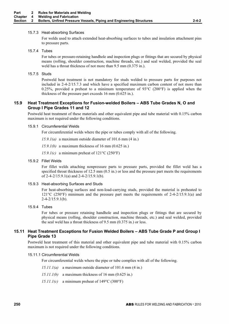
Part 2 Rules for Materials and Welding Chapter 4 Welding and Fabrication Section 2 Boilers, Unfired Pressure Vessels, Piping and Engineering Structures 2-4-2
250 ABS RULES FOR WELDING AND FABRICATION . 2010
15.7.3 Heat-absorbing Surfaces For welds used to attach extended heat-absorbing surfaces to tubes and insulation attachment pins to pressure parts.
15.7.4 Tubes For tubes or pressure-retaining handhole and inspection plugs or fittings that are secured by physical means (rolling, shoulder construction, machine threads, etc.) and seal welded, provided the seal weld has a throat thickness of not more than 9.5 mm (0.375 in.).
15.7.5 Studs Postweld heat treatment is not mandatory for studs welded to pressure parts for purposes not included in 2-4-2/15.7.3 and which have a specified maximum carbon content of not more than 0.25%, provided a preheat to a minimum temperature of 93°C (200°F) is applied when the thickness of the pressure part exceeds 16 mm (0.625 in.).
15.9 Heat Treatment Exceptions for Fusion-welded Boilers – ABS Tube Grades N, O and Group I Pipe Grades 11 and 12 Postweld heat treatment of these materials and other equivalent pipe and tube material with 0.15% carbon maximum is not required under the following conditions.
15.9.1 Circumferential Welds For circumferential welds where the pipe or tubes comply with all of the following.
15.9.1(a) a maximum outside diameter of 101.6 mm (4 in.)
15.9.1(b) a maximum thickness of 16 mm (0.625 in.)
15.9.1(c) a minimum preheat of 121°C (250°F)
15.9.2 Fillet Welds For fillet welds attaching nonpressure parts to pressure parts, provided the fillet weld has a specified throat thickness of 12.5 mm (0.5 in.) or less and the pressure part meets the requirements of 2-4-2/15.9.1(a) and 2-4-2/15.9.1(b).
15.9.3 Heat-absorbing Surfaces and Studs For heat-absorbing surfaces and non-load-carrying studs, provided the material is preheated to 121°C (250°F) minimum and the pressure part meets the requirements of 2-4-2/15.9.1(a) and 2-4-2/15.9.1(b).
15.9.4 Tubes For tubes or pressure retaining handhole and inspection plugs or fittings that are secured by physical means (rolling, shoulder construction, machine threads, etc.) and seal welded, provided the seal weld has a throat thickness of 9.5 mm (0.375 in.) or less.
15.11 Heat Treatment Exceptions for Fusion Welded Boilers – ABS Tube Grade P and Group I Pipe Grade 13 Postweld heat treatment of this material and other equivalent pipe and tube material with 0.15% carbon maximum is not required under the following conditions.
15.11.1 Circumferential Welds For circumferential welds where the pipe or tube complies with all of the following.
15.11.1(a) a maximum outside diameter of 101.6 mm (4 in.)
15.11.1(b) a maximum thickness of 16 mm (0.625 in.)
15.11.1(c) a minimum preheat of 149°C (300°F)

Part 2 Rules for Materials and Welding Chapter 4 Welding and Fabrication Section 2 Boilers, Unfired Pressure Vessels, Piping and Engineering Structures 2-4-2
ABS RULES FOR WELDING AND FABRICATION . 2010 251
15.11.2 Fillet Welds For fillet welds attaching nonpressure parts that have a specified throat thickness of 12.5 mm (0.5 in.) or less, provided the pressure part meets the requirements of 2-4-2/15.11.1(a) and 2-4-2/15.11.1(b).
15.11.3 Heat-absorbing Surfaces and Studs Heat-absorbing surfaces and non-load-carrying studs, provided the material is preheated to 149°C (300°F) and the pressure part meets the requirements of 2-4-2/15.11.1(a) and 2-4-2/15.11.1(b).
15.11.4 Tubes For tubes or pressure retaining handhole and inspection plugs or fittings with a specified maximum chrome content of 6% that are secured by physical means (rolling, shoulder construction, machine threads, etc.) and seal welded, provided the seal weld has a throat thickness of 9.5 mm (0.375 in.) or less.
15.13 Other Materials Postweld heat treatment of other materials for boilerplate and tubes will be subject to special consideration.
15.15 Other Welded Connections Nozzles or other welded attachments for which postweld heat treatment is required may be locally postweld heat-treated by heating a circumferential band around the entire vessel with the welded connection located at the middle of the band. The width of the band is to be at least three times the wall thickness of the vessel wider than the nozzle or other attachment weld, and is to be located in such a manner that the entire band will be heated to the temperature and held for the time specified in 2-4-2/15.1 for post-weld heat treatment.
15.17 Welded Joints In the case of welded joints in pipes, tubes and headers, the width of the heated circumferential band is to be at least three times the width of the widest part of the welding groove, but in no case less than twice the width of the weld reinforcement.
17 Fusion-welded Pressure Vessels
17.1 Postweld Heat Treatment 17.1.1 General
All pressure vessels and pressure-vessel parts are to be given a postweld heat treatment at a temperature not less than that specified in 2-4-2/15.1 and 2-4-2/15.3 when the nominal thickness, including corrosion allowance of any welded joint in the vessel or vessel part exceeds the limits as noted in 2-4-2/17.3 and 2-4-2/17.5. In addition, postweld heat treatment is required for the following.
17.1.1(a) For all independent cargo tanks where required by Part 5C, Chapter 8.
17.1.1(b) For all carbon or carbon manganese steel pressure vessels and independent cargo pressure vessels not covered by 2-4-2/17.1.1(a), when the metal temperature is below -29°C (-20°F).
17.1.1(c) For all pressure vessels and independent cargo pressure vessels, which are fabricated of carbon or carbon manganese steel and intended to carry anhydrous ammonia.
17.1.2 Welded Joints When the welded joint connects parts that are of different thickness, the thickness to be used in applying these requirements is to be the thinner of two adjacent butt-welded plates, including head to shell connections, the thickness of the head or shell plate in nozzle attachment welds, and the thickness of the nozzle neck at the joint in nozzle neck to flange connections, the thickness of the shell in connections to tube sheets, flat heads, covers or similar connections, and the thicker of plate in connections of the type shown in 2-4-2/Figure 1(f).

Part 2 Rules for Materials and Welding Chapter 4 Welding and Fabrication Section 2 Boilers, Unfired Pressure Vessels, Piping and Engineering Structures 2-4-2
252 ABS RULES FOR WELDING AND FABRICATION . 2010
17.3 Heat-treatment Exceptions – ABS Plate Grades MA, MB, MC, MD, ME, MF, MG, K, L, M, N and Tube Grades D, F, G, H, J Postweld heat treatment of these materials is not required under the following conditions.
17.3.1 38.1 mm (1.5 in.) and Under For material up to and including 38.1 mm (1.5 in.) thickness, provided that material over 31.8 mm (1.25 in.) thickness is preheated to a minimum temperature of 93°C (200°F) during welding.
17.3.2 Over 38.1 mm (1.5 in.) For material over 38.1 mm (1.5 in.) thickness, all welded connections and attachments are to be postweld heat-treated except that postweld heat treatment is not required for:
17.3.2(a) Nozzle Connections. Fillet welds with a throat not over 12.7 mm (0.50 in.) and groove welds not over 12.7 mm (0.50 in.) in size that attach nozzle connections having a finished inside diameter not greater than 50.8 mm (2 in.), provided the connections do not form ligaments that require an increase in shell or head thickness, and preheat to a minimum temperature of 93°C (200°F) is applied.
17.3.2(b) Nonpressure Attachments. Fillet welds having a throat not over 12.7 mm (0.5 in.), or groove welds not over 12.7 mm (0.50 in.) in size, used for attaching nonpressure parts to pressure parts, and preheat to a minimum temperature of 93°C (200°F) is applied when the thickness of the pressure part exceeds 19 mm (0.75 in.).
17.5 Heat-treatment Exceptions – ABS Plate Grades H, I, J and Tube Grades K, L, M Postweld heat treatment of these materials is not required under the following conditions.
17.5.1 15.9 mm (0.625 in.) and Under For material up to and including 15.9 mm (0.625 in.) in thickness having a specified maximum carbon content of not more than 0.25%, provided a welding procedure qualification has been made in equal or greater thickness than the production weld.
17.5.2 Over 15.9 mm (0.625 in.) For material over 15.9 mm (0.625 in.) thicknesses, all welded connections and attachments are to be postweld heat-treated, except that postweld treatment is not required for:
17.5.2(a) Nonpressure Attachments. Attaching to pressure parts which have a specified maximum carbon content of not more than 0.25% and nonpressure parts with fillet welds that have a throat thickness of 12.7 mm (0.50 in.) or less, provided preheat to a minimum temperature of 80°C (175°F) is applied.
17.5.2(b) Tube or Pipe Attachments. Circumferential welds in pipes or tubes where the pipes or tubes have both a nominal wall thickness of 12.7 mm (0.50 in.) or less, and a specified maximum carbon content of not more than 0.25%.
17.7 Heat-treatment Exceptions – Attachments On pressure vessels which do not require postweld heat treatment as a whole, connections and other attachments after being attached by fusion welding need not be post-weld heat-treated. See also 2-4-2/21.11 for nozzles or other welded attachments for which postweld heat treatment is not required.
17.9 Other Materials Postweld heat treatment of other materials for boiler plate and tubes will be subject to special consideration.

Part 2 Rules for Materials and Welding Chapter 4 Welding and Fabrication Section 2 Boilers, Unfired Pressure Vessels, Piping and Engineering Structures 2-4-2
ABS RULES FOR WELDING AND FABRICATION . 2010 253
17.11 Welded Connections Nozzles or other welded attachments for which postweld heat treatment is required may be heat-treated by heating a circumferential band around the entire vessel in such a manner that the entire band is to be brought up uniformly to the required temperature and held for the specified time. The circumferential band is to extend around the entire vessel and include the nozzle or welded attachment, and is to extend at least six times the plate thickness beyond the welding which connects the nozzle or other attachment to the vessel. The portion of the vessel outside of the circumferential band is to be protected so that the temperature gradient is not harmful.
19 Pipe Welded Joints and Engineering Structures
19.1 Group I Pipe Welded Joints All Group I Pipe welded joints, defined in 2-4-2/1.5, are to be postweld heat-treated in accordance with 2-4-2/15 or the American National Standard ANSI B31.1.
19.3 Group II Pipe Welded Joints Unless specially required, welded joints in Group II piping need not be postweld heat-treated.
19.5 Group I Engineering Structures All welded structures under this group are to be postweld heat-treated in accordance with the applicable requirements of 2-4-2/17.
19.7 Group II Engineering Structures Postweld heat treatment of structures under this group depends on the type and purpose of the construction, and the matter will be subject to special consideration in connection with the approval of the design.
19.9 Low-temperatures Piping Systems [Below -18°C (0°F)] In general, all piping weldments except socket-weld joints and slip-on flanges, where permitted, are to be postweld heat-treated. Exceptions will be considered for specific materials where it can be shown that postweld heat treatment is unnecessary.
21 Postweld Heat-treatment Details
21.1 Boilers and Pressure Vessels The weldment is to be heated uniformly and slowly to the temperature and time specified in 2-4-2/15.1, and is to be allowed to cool slowly in a still atmosphere to a temperature not exceeding 427°C (800°F). The postweld heat treatment may be done either by heating the complete welded structure as a whole or by heating a complete section containing the parts to be postweld heat-treated. The postweld-heat-treatment temperature is to be controlled by at least two pyrometric instruments to avoid the possibility of error.
21.3 Pipe Connections In the case of welded pipe connections requiring postweld heat treatment, the adjacent pipes or fittings are to be heated in a circumferential band at least three (3) times the width of the widest part of the welding groove but not less than twice the width of the weld reinforcement.
21.5 Other Steels The postweld heat treatment of other steels not specifically covered in Part 2, Chapter 3 will be subject to special consideration.
21.7 Clad Pressure Vessels Postweld heat treatment of vessels or parts of vessels constructed of integrally clad or applied corrosion-resistant lining material will be subject to special consideration.

Part 2 Rules for Materials and Welding Chapter 4 Welding and Fabrication Section 2 Boilers, Unfired Pressure Vessels, Piping and Engineering Structures 2-4-2
254 ABS RULES FOR WELDING AND FABRICATION . 2010
21.9 Opening Connections Welded connections may be added to a vessel after post-weld heat treatment without requiring repostweld heat treatment, provided the following conditions are met.
21.9.1 Size of Weld The inside and outside attachment welds do not exceed 9.5 mm (0.375 in.) throat dimension.
21.9.2 Opening Diameter The diameter of the attachment opening in the vessel shell does not exceed that allowed for an unreinforced opening, or does not exceed 50.8 mm (2 in.), whichever is smaller.
21.9.3 Exception This provision does not apply to those connections so placed as to form ligaments in the shell, the efficiency of which will affect the shell thickness. Such added connections are to be postweld heat-treated.
21.11 Seal Welding Seal welding consisting of a fillet weld under 9.5 mm (0.375 in.) without subsequent stress relieving may be applied to secure tightness of connections where the construction is such that no design stress is placed upon the weld even though the structure itself has to be stress-relieved in accordance with these Rules.
23 Radiography
23.1 General 23.1.1 Welded-joint Preparation
All welded joints to be radiographed are to be prepared as follows: The weld ripples or weld surface irregularities, on both the inside and outside, are to be removed by any suitable mechanical process to such a degree that the resulting radiographic contrast due to any irregularities cannot mask or be confused with the image of any objectionable defect. Also, the weld surface is to merge smoothly into the plate surface. The finished surface of the reinforcement of all butt-welded joints may be flush with the plate or may have a reasonably uniform crown not to exceed the following thickness.
Plate Thickness, in mm (in.) Thickness of Reinforcement, in mm (in.) Up to 12.7 (0.5) incl. 1.6 (1/16)
Over 12.7 (0.5) to 25.4 (1.0) 2.4 (3/32) Over 25.4 (1.0) to 50.8 (2.0) 3.2 (1/8)
Over 50.8 (2.0) 4.0 ( /32)
23.1.2 Radiographic Examination with Backing Strip A single-welded circumferential butt joint with backing strip may be radiographed without removing the backing strip, provided it is not to be removed subsequently and provided the image of the backing strip does not interfere with the interpretation of the resultant radiographs.
23.1.3 Details of Radiographic Search See 2-4-3/9 for further details of radiographic search of finished joints.
23.3 Boilers All circumferential, longitudinal, and head joints are to be examined for their full length by radiography except that parts of boilers fabricated of pipe material, such as drums, shells, downcomers, risers, cross-pipes, headers, and tubes are to be nondestructively examined as required by 2-4-2/23.7.

Part 2 Rules for Materials and Welding Chapter 4 Welding and Fabrication Section 2 Boilers, Unfired Pressure Vessels, Piping and Engineering Structures 2-4-2
ABS RULES FOR WELDING AND FABRICATION . 2010 255
23.5 Other Pressure Vessels 23.5.1 Full Radiography
Double-welded butt joints or their equivalent are to be examined radiographically for their full length under any of the following conditions.
23.5.1(a) Joint Efficiency. Where the design of the vessel or vessel section is based on the use of the joint efficiency tabulated in column (a) of 4-4-1A1/Table 1.
23.5.1(b) Material Used. Complete radiographic examination is required for each butt-welded joint in vessels built of Steel Plate for Boilers and Pressure Vessels ABS Grades, MA, MB, MC, MD, ME, MF, MG, K, L, M and N having a thickness in excess of 31.8 mm (1.25 in.) as well as for ABS Grades H, I and J having a thickness in excess of 19 mm (0.75 in.). Other steels not specifically covered in Part 2, Chapter 3 will be subject to special consideration.
23.5.2 Spot (Random) Radiography All longitudinal and circumferential double-welded butt joints or their equivalent which are not required to be fully radiographed in 2-4-2/23.5.1 are to be examined by spot (random) radiography where the pressure vessel or pressure vessel section is based on the use of the joint efficiency tabulated in column (b) of 4-4-1A1/Table 1. The extent of spot radiography is to compare favorably with accepted practice such as that specified in the ASME Boiler and Pressure Vessel Code and is to be the satisfaction of the Surveyor.
23.7 Group I Pipe Connections (1999) Group I pipe connections are to be radiographically examined according to either of the conditions indicated below, as applicable.
Pipe Size Extent of Radiography (1,2) Wall Thickness > 9.5 mm (3/8 in.) 100% Diameter > 76.1 mm (3.0 in) O.D. 100%
Notes 1 Where radiographic testing is not practicable, such as for fillet welds,
another effective method of nondestructive testing is to be carried out.
2 Where radiographic testing is not required in the above table, alternative nondestructive testing, magnetic particle or penetration methods, may be required by the attending Surveyor when further inspection deems it necessary
23.9 Group II Pipe Connections (1999) Spot (random) radiographic or ultrasonic examination of welded joints with an outer diameter greater than 101.6 mm (4.0 in) may be required by the Surveyor when further inspection deems it necessary.
23.11 Low Temperature Piping Connections [Below -18°C (0°F)] In all carbon and alloy steel piping with a service temperature below -18°C (0°F) and an inside diameter of more than 75 mm (3 in.) or where the wall thickness exceeds 10 mm or 0.375 in., welds made in accordance with this group are to be subjected to 100% radiographic search or to other approved method of test if the former is not practicable. For pipe of smaller diameter or thickness, welds are to be subjected to spot (random) radiographic examination or to other approved methods of test of at least 10% of the welds, to the satisfaction of the Surveyor.
23.13 Group I Engineering Structures Group I Engineering Structures are to meet the same radiographic requirements as Group I Pressure Vessels.
23.15 Group II Engineering Structures Group II Engineering Structures which correspond in service requirements to Group II Pressure Vessels are not required to be subjected to a full or spot (random) radiographic examination of welded joints.
Part 2 Rules for Materials and Welding Chapter 4 Welding and Fabrication Section 2 Boilers, Unfired Pressure Vessels, Piping and Engineering Structures 2-4-2
256 ABS RULES FOR WELDING AND FABRICATION . 2010
23.17 Engine Bedplates Bedplates for main propulsion internal-combustion engines with cylinders 458 mm (18 in.) in diameter and over are to be examined radiographically or ultrasonically in way of principal welds.
23.19 Miscellaneous 23.19.1 Alloy and Clad Pressure Vessels
The radiographic examination of vessels or parts of vessels constructed of alloy, integrally clad or applied corrosion-resistant lining materials, will be subject to special consideration.
23.19.2 Nozzles, Sumps, etc. Butt welds of inserted-type nozzles are to be radiographed when used for attachment to a vessel or vessel section that is required to be radiographed or the joint efficiency tabulated in column (a) of 4-4-1A1/Table 1 is used. Nozzles and manhole attachment welds which are not of the double-welded butt-type need not be radiographed. Joints used in the fabrication of nozzles, sumps, etc. are to be radiographed when intended for installation in a vessel or vessel section that is required to be radiographed or when the joint efficiency tabulated in column (a) of 4-4-1A1/Table 1 is used, except that circumferential-welded butt joints of nozzles and sumps not exceeding 254 mm (10 in.) nominal pipe size or 28.6 mm (1.125 in.) wall thickness need not be radiographed.
25 Hydrostatic Test
25.1 Boilers and Pressure Vessels Hydrostatic tests are to be conducted in accordance with 4-4-1/7.11 and 4-4-1A1/21.
25.3 Piping Hydrostatic tests are to be conducted in accordance with the Table 1 below:
TABLE 1 Hydrostatic Testing of Piping
SVR* SVR<90m* MODU* Class I Class II Class III Group I Group II Group I Group II
4-6-2/7.3 4-6-2/7.3 4-6-2/7.3.1 4-4-2/3 4-4-2/3 6-1-1/13 6-1-1/13 4-6-7/7.7 4-4-2/5.1 6-1-1/21
* Notes SVR – Rules for Building and Classing Steel Vessels SVR<90m – Rules for Building and Classing Steel Vessels Under 90 meters (295 feet) in Length MODU – Rules for Building and Classing Mobile Offshore Drilling Units
For conditions of hydrostatic testing in other Rules and Guides, see the requirements within the relevant Rules or Guides.
25.5 Defects Pinholes, cracks or other defects are to be repaired only by chipping, machining or burning out the defects and rewelding. Boiler drums and vessels requiring stress relieving are to be stress-relieved after any welding repairs have been made.
25.7 Retest After repairs have been made, the drum, vessel or piping is to be again subjected to the hydrostatic test required in 2-4-2/25.1 through 2-4-2/25.3, inclusive.
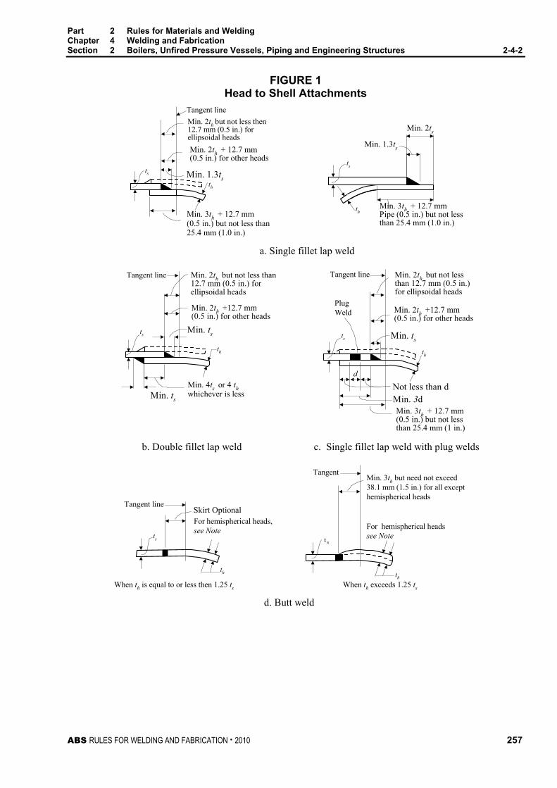
Part 2 Rules for Materials and Welding Chapter 4 Welding and Fabrication Section 2 Boilers, Unfired Pressure Vessels, Piping and Engineering Structures 2-4-2
ABS RULES FOR WELDING AND FABRICATION . 2010 257
FIGURE 1 Head to Shell Attachments
Min. 2th but not less then12.7 mm (0.5 in.) forellipsoidal heads
Tangent line
ts
Min. 2th + 12.7 mm(0.5 in.) for other heads
Min. 1.3tsth
Min. 3th + 12.7 mm(0.5 in.) but not less than25.4 mm (1.0 in.)
thMin. 3th + 12.7 mmPipe (0.5 in.) but not lessthan 25.4 mm (1.0 in.)
Min. 2ts
Min. 1.3ts
ts
a. Single fillet lap weld
Tangent line Min. 2th but not less than12.7 mm (0.5 in.) forellipsoidal heads
Min. 2th +12.7 mm(0.5 in.) for other heads
Min. ts
th
Min. ts
ts
b. Double fillet lap weld
Min. 4ts or 4 thwhichever is less
d
Tangent line Min. 2th but not lessthan 12.7 mm (0.5 in.)for ellipsoidal heads
Min. 2th +12.7 mm(0.5 in.) for other heads
Min. tsts
PlugWeld
Min. 3dNot less than d
Min. 3th + 12.7 mm(0.5 in.) but not lessthan 25.4 mm (1 in.)
c. Single fillet lap weld with plug welds
th
st
d. Butt weld
Tangent line
ts
th
Skirt OptionalFor hemispherical heads,see Note
When th is equal to or less then 1.25 ts
th
TangentMin. 3th but need not exceed38.1 mm (1.5 in.) for all excepthemispherical heads
For hemispherical headssee Note
When th exceeds 1.25 ts

Part 2 Rules for Materials and Welding Chapter 4 Welding and Fabrication Section 2 Boilers, Unfired Pressure Vessels, Piping and Engineering Structures 2-4-2
258 ABS RULES FOR WELDING AND FABRICATION . 2010
FIGURE 1 (continued) Head to Shell Attachments
Min. ts
Min. 3th butneed not exceed38.1 mm (1.50 in.)Tangent Line
Taper Optional
Min. 1.3tsth
ts
e. Single fillet lap weld
th
ts2
2thmin.
2thmin.
ts1
Butt weld and fillet weld if used, are to bedesigned to take shear at 1.5 times the
differential pressure that can exist
ts1 and ts2 may be different
f. Intermediate head
LD.
TangentPoint
Butt Weld
Seal orfillet weldoptional
Need not exceed25.4 mm (150 in.)
15° to 20°
12.7 mm(0.5 in.)
ts
t1
tt1 min = 1.25t or 1.25ts whichever
is the smaller.
g.
ts
t1
t1 min = t or ts whicheveris the greater
t
h.
Min 30°Max 45°
Bevel Optional 2½t max.t min.
tt1
As Desired
1½t min.
Depth of offset = t1Pressure on this side
Avoid sharp break
t or t1 = 15.9 mm (5/8 in.) max.
j. Butt weld with one plate edge offset

Part 2 Rules for Materials and Welding Chapter 4 Welding and Fabrication Section 2 Boilers, Unfired Pressure Vessels, Piping and Engineering Structures 2-4-2
ABS RULES FOR WELDING AND FABRICATION . 2010 259
FIGURE 1 (continued) Head to Shell Attachments
Notpermissible
Preferred method Permissiblefor circumferential
joints only
Tapered oneside only(inside oroutside)
31 1
3 31
k. Butt welding of plates of unequal thickness
m. Example of corner weld subject to bending stress(not permissible)
Note: Dished heads of full hemispherical shape, concave to pressure, intended for butt-welded attachment, need
not have an integral skirt, but where one is provided, the thickness of the skirt is to be at least that required for a seamless shell of the same diameter.

Part 2 Rules for Materials and Welding Chapter 4 Welding and Fabrication Section 2 Boilers, Unfired Pressure Vessels, Piping and Engineering Structures 2-4-2
260 ABS RULES FOR WELDING AND FABRICATION . 2010
FIGURE 2 Types of Fusion-welded Construction Details
Backing strip if used may be removed after welding
tc
a b
tc
c
tc
d
tnt1
t2
t
e-1
t1
tn
t2t
e-2
t
tn
t1
t2
t1 + t2 = 11/4tmin t1 or t2 not less than the smaller of 6.4 mm (1/4 in.) or 0.7tmin
f
tn
t1
t2
t
tc
g
tc
h
tc
Typical flush type nozzles
k
dtw =0.7tmin
tn
t
1/2tmin
l
Weldto shell
t
tn
1/2tmin
tw =0.7tmin
te
tc
m
to padWeld
t
1/2tmin
te
tw =0.7tmin
tc

Part 2 Rules for Materials and Welding Chapter 4 Welding and Fabrication Section 2 Boilers, Unfired Pressure Vessels, Piping and Engineering Structures 2-4-2
ABS RULES FOR WELDING AND FABRICATION . 2010 261
FIGURE 2 (continued) Types of Fusion-welded Construction Details
tn tc
te
t
½tmin
tw =0.7tmin
n
½tmin
tn
tcte
t
o
½tmin
tntc
te
t
te½tmin
tc
tw =0.7tmin
p
13
tn
t
q-1 q-3
t t3
t4
tn
te30°min12.7 mm
(½ in.) min.
6.4 mm(¼ in.) R min.
t3 + t4 ≤ 0.2t but not greater than 6.4 mm (1/4 in.)
45°max
30°max
t1½t min.
te
tn
q-2
19.1 mm(¾ in.) R min.
tn
t
q-4 r-1
tn
30°min
tw = 0.7tmin
t
6.4 mm(¼ in.)
te1½t min.
tn
Less than 30°
½t min.
tw = 0.7tmin
t
6.4 mm(¼ in.)
te = 0
r-2
30° min
tw = 0.7tmin
tn
te
tw = 0.7tmind
t
s
tw = 0.7tmin
te
t
d½t min.
t

Part 2 Rules for Materials and Welding Chapter 4 Welding and Fabrication Section 2 Boilers, Unfired Pressure Vessels, Piping and Engineering Structures 2-4-2
262 ABS RULES FOR WELDING AND FABRICATION . 2010
FIGURE 2 (continued) Types of Fusion-welded Construction Details
Either method of attachment is satisfactory
t1t2
tc
tc
tc
t1
t2
t1
tc
t2
t1 + t2 = 11/4tmin t1 or t2 not less than the smaller of 6.4 mm (1/4 in.) or 0.7tmin
u-1 u-2 v-1 v-2 w-1 w-2 89mm OD (3in. NPS) max
64 mm(¼ in.) min.
tw
w-3
½tmin
tw = 0.7tmin
x
tctn
1.6 mm(1/16 in.)recess
tn but notless than6.4 mm(¼ in.)
tw
y
tn but notless than6.4 mm(¼ in.)
tw
tc
section 1-1
1.6 mm(1/16 in.)recess
z
tc
tn
1
1
Typical Tube Connections
(When used for other than square, round, or oval headers, round off corners)
t = thickness of vessel shell or head, less corrosion allowance, in mm (in.) tn = thickness of nozzle wall, less corrosion allowance, in mm (in.)
te = thickness of reinforcing element, mm (in.)
tw = dimension of partial-penetration attachment welds (fillet, single-bevel, or single-J), measured as shown, mm (in.)
tc = the smaller of 6.4 mm (1/4 in.) or 0.7 tmin. (Inside corner welds may be further limited by a lesser length of projection of the nozzle wall beyond the inside face of the vessel wall.)
tmin = the smaller of 19.1 mm (3/4 in.) or the thickness of either of the parts joined by a fillet, single-bevel, or single-J weld, mm (in.)

ABS RULES FOR WELDING AND FABRICATION . 2010 263
P A R T S e c t i o n 3 : W e l d T e s t s
2 C H A P T E R 4 Welding and Fabrication
S E C T I O N 3 Weld Tests
1 General The steps to be taken in obtaining approval by the Bureau of electrodes and welding procedures for qualifying welders and for demonstrating satisfactory workmanship are given below.
1.1 Weld Groups The various groups of welds are designated by index letters and numbers, by which they are referred to in subsequent paragraphs, as follows.
Hull Construction H All hull structures
Boilers, etc. Group I B1
Unfired Pressure Vessels Group II B2
Piping Group I P1 As defined in 2-4-2/1.5
Piping Group II P2
Engineering Structures Group I E1
Engineering Structures Group II E2
1.3 Tests Details of tests, preparation of specimens and test results required for approval in each application are given in 2-4-3/3 to 2-4-3/9, and 2-4-3/Figure 1 to 2-4-3/Figure 13. Where the position of welding is referred to, the same is to be defined in the American Welding Society definitions.
3 Filler Metals
3.1 General (1997) Filler metals are to be a type suitable to produce sound welds that have strength and toughness comparable to the materials being welded. The Bureau maintains a separately issued list of approved filler metals entitled, “Approved Welding Consumables.” This list indicates the grade and general application for which such filler metals may be employed. It is intended that this list will serve as a useful guide in the selection of suitable filler metals for various welding applications.
3.3 Approval Basis (2005) Filler metals will be approved and listed, subject to tests conducted at a manufacturer’s plant or alternatively, at a location outside of the manufacturer’s plant under the supervision of the manufacturer. Upon satisfactory completion of tests, a certificate will be issued for general approval, indicating, where applicable, the ABS Grade, operating characteristics and limits of application. Test assemblies are to be prepared in the presence of the Surveyor and all tests are to be carried out in the Surveyor’s presence and to the Surveyor’s satisfaction. Procedure and testing are to comply with either of the following standards.

Part 2 Rules for Materials and Welding Chapter 4 Welding and Fabrication Section 3 Weld Tests 2-4-3
264 ABS RULES FOR WELDING AND FABRICATION . 2010
3.3.1 Bureau Standards Approval of filler metals for welding vessels and other engineering structures will be granted upon compliance with the Requirements for the Approval of Filler Metals contained in Part 2, Appendix 2.
3.3.2 Standards of Other Agencies Filler metals will be considered for approval based upon tests conducted to standards established by The American Welding Society or other recognized agencies.
3.3.3 Special Approval Under circumstances where exact specifications have not been established, the Bureau will consider approval on the basis of a filler metal manufacturer’s guaranteed requirements. Qualified approvals will also be considered, with and without classifying as to grade, for special applications with reliance upon procedure tests at a user’s plant.
5 Approval of Welding Procedures
5.1 Approved Filler Metals The type of approved filler metals used on Bureau-classed weldments will depend upon the specific application for which the filler metal is intended. Procedure tests may be required at the discretion of the attending Surveyor to determine the shipyard or fabricator’s capability in the application of the proposed filler metal to the base material. The extent of such tests may vary depending upon the intended application, but generally are to follow those tests outlined in 2-4-3/5.7.
5.3 Surveyor’s Acceptance The Surveyor may, at his discretion, accept a filler metal, welding procedure, or both, in a shipyard or fabricator’s plant where it is established to the Surveyor’s satisfaction that they have been effectively used for similar work under similar conditions.
5.5 New Procedures and Methods Weld tests using procedures and materials similar to those intended for production welding may be required to be prepared by each shipyard or fabricator when new or unusual methods, base metals or filler metals are proposed. All tests are to be made in the presence of the Surveyor and carried out to the Surveyor’s satisfaction.
5.7 Tests (2006) See 2-4-3/Figure 1. Unless otherwise approved, the number of specimens is to be as indicated. The minimum test results required are stated with the following figures.
• Test No. 1 (For butt welds) Reduced-section Tension Test (2-4-3/Figure 3 or 2-4-3/Figure 4). One test assembly for each position involved; two reduced-section tension test specimens taken from each test assembly as shown in 2-4-3/Figure 1.
• Test No. 2 (For butt welds) Guided Bend Test (2-4-3/Figure 5 and 2-4-3/Figure 6). One test assembly for each position involved. For material 19 mm (0.75 in.) thick and under, two face-bend and two root-bend specimens taken from each test assembly as shown in 2-4-3/Figure 1, except that at the option of the fabricator, four side bends may be substituted for material thickness over 9.5 mm (3/8 in.). For material over 19 mm (0.75 in.) thick, four side-bend specimens taken from each test assembly as shown in 2-4-3/Figure 1. The bending jig and test requirements are indicated in 2-4-3/Figure 7.
• Test No. 3 Fillet-weld Test (2-4-3/Figure 8). One specimen made in each position involved.
5.9 Special Tests All weld-metal tension, Charpy V-notch impact, macro-etch or other relevant tests may be required for certain applications, such as higher-strength steels, electroslag welding, one-side welding, etc., and the results submitted for consideration. 2-4-3/Figure 13 defines the location of Charpy V-notch impact tests when heat affected zone tests are required. A Charpy V-notch test is to consist of three specimens per location.

Part 2 Rules for Materials and Welding Chapter 4 Welding and Fabrication Section 3 Weld Tests 2-4-3
ABS RULES FOR WELDING AND FABRICATION . 2010 265
5.11 Repair and Cladding of Stern Tube and Tail Shafts Weld repairs and cladding on stern tube shafts and tail shafts are to be performed in an approved facility.
Approval of welding procedures for the repair or cladding of stern tube shafts and tail shafts is to be in accordance with Appendix 7-A-11 “Guide for Repair and Cladding of Shafts” of the ABS Rules for Survey After Construction (Part 7).
7 Workmanship Tests
7.1 Hull Construction The Surveyor may, when it is considered desirable, require welders to prepare specimens for Fillet-weld Tests (Test No. 3) for the positions involved. Details of the specimen are shown in 2-4-3/Figure 8.
7.3 Boilers and Group I Pressure Vessels 7.3.1 Required Tests
The following tests are to be conducted/performed using equivalent material of the same thickness as the boiler or pressure vessel. The results required are stated with the applicable figures and in 2-4-3/9.3.
• Test No. 1 Reduced-section Tension Test (2-4-3/Figure 3)
• Test No. 2 Guided Bend Test, (2-4-3/Figure 5 or 2-4-3/Figure 6)
• Test No. 3 Radiographic Search of Welds on Finished Joint
7.3.2 Test Exceptions Test Nos. 1 and 2 are not required for cylindrical pressure parts of Boilers and Group I Pressure Vessels constructed of ABS Steel Plate for Boilers and Pressure Vessels Grades A through G inclusive and Grades K through N inclusive whose welded joints are fully examined by radiography.
7.3.3 Attached Test Plates Structures made in accordance with the requirements of Group B1 of materials other than those given in 2-4-3/7.3.2 are to have test plates attached as shown in 2-4-3/Figure 2 to permit the longitudinal joint of the shell and test plates to be welded continuously. The test plate is to be of sufficient length to provide two specimens for each of Tests Nos. 1 and 2 detailed above. One specimen is to be tested; the other specimen is for use in retesting, if necessary.
7.3.4 Separate Test Plates Circumferential joints of a boiler or pressure vessel need not be provided with test plates unless there be no longitudinal welded joint, in which case, test plates are required to be welded separately.
7.3.5 Number of Test Plates Where several drums or vessels of the same design and grade of material are welded in succession, a set of test plates for each linear 61 m (200 ft) of longitudinal joints, or 61 m (200 ft) of circumferential joints where there are no longitudinal joints, will be acceptable, provided the joints are welded by the same operators and the same welding method. Shells having no longitudinal joints may be considered as being of the same design if the plate thicknesses fall within a range of 6.4 mm (0.25 in.) and the shell diameters do not vary by more than 150 mm (6 in.).
7.3.6 Test-plate Heat Treatment and Retests In all cases, the welded test plates are to be treated as to stress relieving, etc., in the same manner as the work which they represent. Should any of the tests fail, one retest is to be made for each failure; and should the retest also fail, the welding represented is to be chipped or gouged out and rewelded and new test plates provided.

Part 2 Rules for Materials and Welding Chapter 4 Welding and Fabrication Section 3 Weld Tests 2-4-3
266 ABS RULES FOR WELDING AND FABRICATION . 2010
7.5 Other Pressure Vessels Workmanship test plates are not required for structures in this Group. Test No. 3 is to be carried out when required in 2-4-2/23.3.
7.7 Group I Pipe Connections In carbon and carbon-molybdenum steel piping for all diameters where the thickness exceeds 9.5 mm (0.375 in.) and other alloy-steel piping 76 mm (3 in.) in diameter and over regardless of thickness, welds made in accordance with the requirements of this group are to be subjected to 100% Radiographic Search - Test No. 3, or to other approved method of test, where the former is not applicable.
7.9 Group II Pipe Connections No workmanship tests are required.
7.11 Group I Engineering Structures Group I Engineering Structures are to meet the same requirements as 2-4-3/7.3, except that where there is no longitudinal joint, no test plates will be required.
7.13 Group II Engineering Structures Welds in structures in this group which correspond in service requirements to Group B2 are to be tested in the same manner as Group B2, except that where there is no longitudinal joint, no tests will be required.
9 Radiographic or Ultrasonic Inspection
9.1 Hull Construction Where radiographic or ultrasonic inspection is required, such testing should be carried out in accordance with the Bureau’s separately issued Guide for Nondestructive Inspection of Hull Welds.
9.3 Boilers and Pressure Vessels 9.3.1 General
When a radiographic search of the finished joint is required, as indicated in 2-4-3/7.3, 2-4-3/7.5, 2-4-3/7.7 and 2-4-3/7.11, the radiographs are to be obtained by means of an approved technique and are to compare favorably with accepted standards.
9.3.2 Acceptability of Welds-Full Radiography In general, sections of weld that are shown by full radiography to have any of the following types of imperfections are to be considered unacceptable and are to be repaired.
9.3.2(a) Incomplete Fusion or Penetration. Any type of crack or zone of incomplete fusion or penetration
9.3.2(b) Elongated Slag Inclusions or Cavities. Any elongated slag inclusion or cavity which has a length greater than the following, where t is the thickness of the thinner plate being welded
6.4 mm (0.25 in.) for t up to 19.1 mm (0.75 in.) 1/3 t for t from 19.1 mm (0.75 in.) to 57.2 mm (2.25 in.)
19.1 mm (0.75 in.) for t over 57.2 mm (2.25 in.)
9.3.2(c) Slag Inclusion in Line. Any group of slag inclusions in line that have an aggregate length greater than t in a length of 12t, except when the distance between the successive imperfections exceeds 6L where L is the length of the longest imperfection in the group
9.3.2(d) Porosity Standards. Porosity in excess of that permitted by accepted porosity standards such as given in the American Society of Mechanical Engineers’ (ASME) Boiler and Pressure Vessel Code.

Part 2 Rules for Materials and Welding Chapter 4 Welding and Fabrication Section 3 Weld Tests 2-4-3
ABS RULES FOR WELDING AND FABRICATION . 2010 267
9.3.3 Acceptability of Welds-Spot (Random) Radiography The inspection of the production welds by spot radiography is to compare favorably with accepted standards and methods, such as given in the ASME Boiler and Pressure Vessel Code.
9.3.4 Survey Report Data In each case, a statement on the extent and the results of the radiographic examination is to accompany the Surveyor’s report. The inspection procedure and technique is to be maintained on file by the manufacturer and is to compare favorably with accepted practice such as that specified in the ASME Boiler and Pressure Vessel Code.
9.3.5 Pipe-joint Exception An approved method of test may be used in lieu of the radiographic inspection of pipe joints, where the latter cannot be applied.
11 Welders
11.1 General Requirements The Surveyor is to be satisfied that the welders are proficient in the type of work which they are called upon to perform, either through requiring any or all of the tests outlined in the following paragraphs or through due consideration of the system of employment, training, apprenticeship, plant testing, inspection, etc., employed.
11.3 Qualification Tests (2010) The tests, if required for qualification in the various positions for different materials and thicknesses, are given in 2-4-3/Table 1. The tests are referred to by Nos. Q1 to Q4 inclusive for which specimens are to be prepared in accordance with 2-4-3/Figure 9 to 2-4-3/Figure 12 respectively, and physically tested if the welder is qualified by this method. Alternatively, upon the request of the employer, the welder may be qualified by use of radiography, except for gas metal arc welding with the short circuit transfer technique for which bend tests are required. Test assemblies for either physical testing or radiographic examination are to be prepared according to material thickness and welding position, as indicated in 2-4-3/Table 1.
As an alternative, welders may be qualified in accordance with a recognized standard. The application of such recognized standard is to be submitted for agreement by the Surveyor.
11.5 Tests Nos. Q1, Q2, Q3, and Q4 Specimens for qualification Tests Nos. Q1, Q2, Q3 and Q4 are to be bent in a bending jig having the profile shown in 2-4-3/Figure 7.
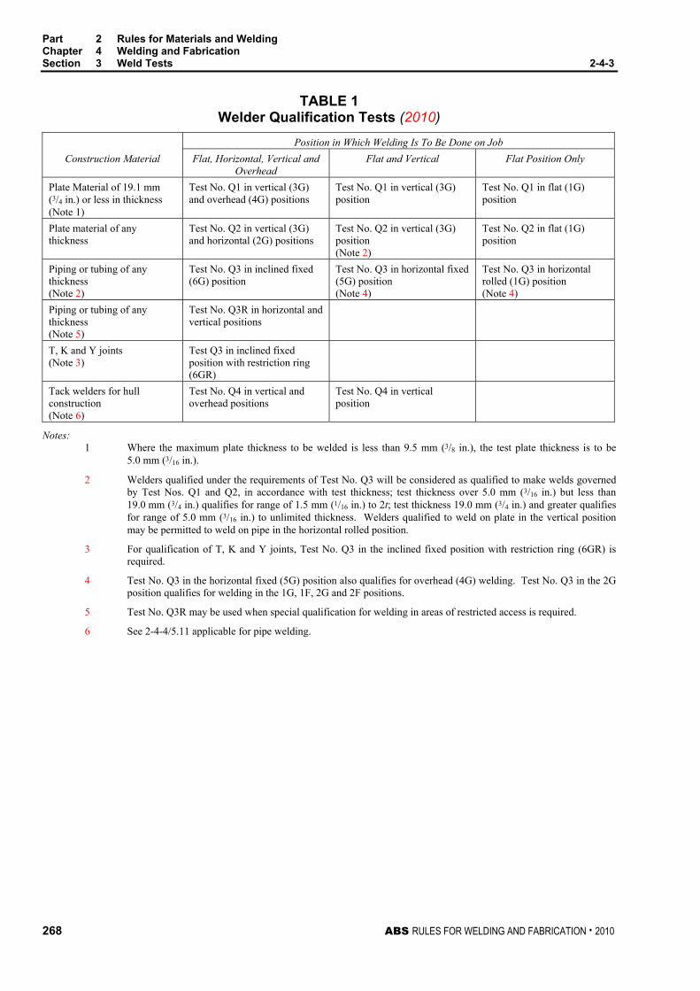
Part 2 Rules for Materials and Welding Chapter 4 Welding and Fabrication Section 3 Weld Tests 2-4-3
268 ABS RULES FOR WELDING AND FABRICATION . 2010
TABLE 1 Welder Qualification Tests (2010)
Position in Which Welding Is To Be Done on Job Construction Material Flat, Horizontal, Vertical and
Overhead Flat and Vertical Flat Position Only
Plate Material of 19.1 mm (3/4 in.) or less in thickness (Note 1)
Test No. Q1 in vertical (3G) and overhead (4G) positions
Test No. Q1 in vertical (3G) position
Test No. Q1 in flat (1G) position
Plate material of any thickness
Test No. Q2 in vertical (3G) and horizontal (2G) positions
Test No. Q2 in vertical (3G) position (Note 2)
Test No. Q2 in flat (1G) position
Piping or tubing of any thickness (Note 2)
Test No. Q3 in inclined fixed (6G) position
Test No. Q3 in horizontal fixed (5G) position (Note 4)
Test No. Q3 in horizontal rolled (1G) position (Note 4)
Piping or tubing of any thickness (Note 5)
Test No. Q3R in horizontal and vertical positions
T, K and Y joints (Note 3)
Test Q3 in inclined fixed position with restriction ring (6GR)
Tack welders for hull construction (Note 6)
Test No. Q4 in vertical and overhead positions
Test No. Q4 in vertical position
Notes: 1 Where the maximum plate thickness to be welded is less than 9.5 mm (3/8 in.), the test plate thickness is to be
5.0 mm (3/16 in.).
2 Welders qualified under the requirements of Test No. Q3 will be considered as qualified to make welds governed by Test Nos. Q1 and Q2, in accordance with test thickness; test thickness over 5.0 mm (3/16 in.) but less than 19.0 mm (3/4 in.) qualifies for range of 1.5 mm (1/16 in.) to 2t; test thickness 19.0 mm (3/4 in.) and greater qualifies for range of 5.0 mm (3/16 in.) to unlimited thickness. Welders qualified to weld on plate in the vertical position may be permitted to weld on pipe in the horizontal rolled position.
3 For qualification of T, K and Y joints, Test No. Q3 in the inclined fixed position with restriction ring (6GR) is required.
4 Test No. Q3 in the horizontal fixed (5G) position also qualifies for overhead (4G) welding. Test No. Q3 in the 2G position qualifies for welding in the 1G, 1F, 2G and 2F positions.
5 Test No. Q3R may be used when special qualification for welding in areas of restricted access is required.
6 See 2-4-4/5.11 applicable for pipe welding.

Part 2 Rules for Materials and Welding Chapter 4 Welding and Fabrication Section 3 Weld Tests 2-4-3
ABS RULES FOR WELDING AND FABRICATION . 2010 269
FIGURE 1 Preparation of Test Plates and Pipes for Weld Tests Nos. 1 and 2
(10in.) min
See2-4-3/Figure 3
1.5t
9.5 mm(3/8 in.)
9.5 mm
t = thickness of plate
See2-4-3/Figure 3
38 mm
9.5 mm(3/8 in)
5° max
5° max
Note: Edge proparation, welding procedure and postweld heat treatment, if any, are to be the same as those for the work represented.
Discard
Face bend
Reduced section
Root bend
Face bend
Root bend
Reduced section
Discard
Reduced section
Discard
Side bend
Side bend
Side bend
Side bendDiscard
Reduced section
For Plate Up To 19.0 mm (3/4 in.) Thick
For Plate Over 19.0 mm (3/4 in.) Thick
250 mm(3/8 in.)
(1 1/2 in.)
About 280 mm (11 in.)
(16 in.) min400 mm
About 280 mm (11 in.)
38 mm(1 1/2 in.)
38 mm(1 1/2 in.)

Part 2 Rules for Materials and Welding Chapter 4 Welding and Fabrication Section 3 Weld Tests 2-4-3
270 ABS RULES FOR WELDING AND FABRICATION . 2010
FIGURE 1 (continued) Preparation of Test Plates and Pipes for Weld Tests Nos. 1 and 2
Side bend
For Pipe Over 19.0 mm (3/4 in.) Thick
t = thickness of pipe
Side bend
Side bend
Reduced section
Reduced section
For Pipe Up To 19.0 mm (3/4 in.) Thick
Face bend
Reduced section
Reduced section
Root bend
Face bend
Root bend
9.5 = mm (3/8 in.)
Note: Edge preparation, welding procedure and postweld heat treatment, if any, are to be the same as those for the work represented.
Side bend

Part 2 Rules for Materials and Welding Chapter 4 Welding and Fabrication Section 3 Weld Tests 2-4-3
ABS RULES FOR WELDING AND FABRICATION . 2010 271
FIGURE 2 Typical Arrangement of Test Plates for Workmanship Tests in Group B1
Test Plate
Boiler or pressurevessel
Welded seam
Tack weldedTestplate(9 in.)
(9 in.)
Length to suit No.of tests required
230 mm
230 mm
Note: Tack weld test plates together and support test assembly so that warping due to welding does not cause
deflection of more than 5 degrees. Should straightening of any test assembly within this limit be necessary to facilitate making test specimens, the test assembly is to be straight-ended after cooling and before any postweld heat treatment.

Part 2 Rules for Materials and Welding Chapter 4 Welding and Fabrication Section 3 Weld Tests 2-4-3
272 ABS RULES FOR WELDING AND FABRICATION . 2010
FIGURE 3 Test No. 1 – Reduced-section Tension Test for Plate
6 mm (¼ in.)
6 mm (¼ in.)6 mm (¼ in.)
50 mm(2 in.) R
Required for all Procedure Qualification and for Workmanship in Group B1 and E1
About 250 mm (10 in.)
Weld
t
W
Notes
1 Both faces of weld are to be machined flush with base metal.
2 For procedure qualification t = 9.5 mm (3/8 in.) for construction materials up to 19.0 mm (3/4 in.). For construction material over 19.0 mm (3/4 in.) t = thickness of material.
3 For workmanship tests t = thickness of construction material.
4 W = approximately 38 mm (1.5 in.) where t is 25.4 mm (1 in.) or less. W = 25.4 mm (1 in.) where t is more than 25.4 mm (1 in.).
5 When the capacity of the available testing machine does not permit testing of the full thickness specimen, two or more thinner than full thickness specimens may be prepared by cutting the full thickness specimen into sections, each of which is to meet the requirements.
Requirements 1 The tensile strength of each specimen, when it breaks in the weld, is not to be less than the minimum
specified tensile strength of the base material.
2 The tensile strength of each specimen, when it breaks in the base metal and the weld shows no signs of failure, is not to be less than 95% of the minimum specified tensile strength of the base material.

Part 2 Rules for Materials and Welding Chapter 4 Welding and Fabrication Section 3 Weld Tests 2-4-3
ABS RULES FOR WELDING AND FABRICATION . 2010 273
FIGURE 4 Test No. 1 – Reduced-section Tension Test for Pipe
Required for all Procedure Qualification and for Workmanship in Group B1 and E1
6mm (¼ in.)
19mm(¾ in.)
6mm (¼ in.)6mm (¼ in.)
50 mm(2 in) R
f
f
About 250 mm (10 in.)
Weld t
Notes
1 Both faces of weld are to be machined flush with base metal. The minimum amount needed to obtain plane parallel faces over 19 mm (3/4 in.) wide reduced section may be machined at the option of the testing facility.
2 For procedure qualification t = 9.5 mm (3/4 in.) for construction materials up to 19.0 mm (3/4 in.). For construction material over 19.0 mm (3/4 in.) t = thickness of material.
3 For workmanship tests t = thickness in material.
4 When the capacity of the available testing machine does not permit testing of the full thickness specimen, two or more thinner than full thickness specimens may be prepared by cutting the full thickness specimen into sections, each of which is to meet the requirements.
Requirements 1 The tensile strength of each specimen, when it breaks in the weld, is not to be less than the minimum
specified tensile strength of the base material.
2 The tensile strength of each specimen, when it breaks in the base metal and the weld shows no signs of failure, is not to be less than 95% of the minimum specified tensile strength of the base material.

Part 2 Rules for Materials and Welding Chapter 4 Welding and Fabrication Section 3 Weld Tests 2-4-3
274 ABS RULES FOR WELDING AND FABRICATION . 2010
FIGURE 5 Test No. 2 – Guided Bend Test for Root Bend and Face Bend
(Plate or Pipe) (2007) Required for Procedure Qualification, Workmanship Tests in Groups B1, B2 , and E1
PLATE PIPE
38 mm(1½ in.)
38 mm(1½ in.)
9.5 mm(3/8 in.)
150 mm (6 in.) 150 mm (6 in.)
Face Bend
Root Bend
T
9.5 mm (3/8 in.)
9.5 mm (3/8 in.)
T
Both faces of weld to be machined flush with base metal.On test assmeblies greater than 9.5 mm (3/8 in.) the opposite side of specimen may bemachined as shown.
Note:
FIGURE 6 Test No. 2 – Guided Bend Test for Side Bend (Plate or Pipe) (1996)
150 mm(6 in.) min
9.5 mm(3/8 in.)
Note Faces of weld to be machined flush with base metal
Full material thickness is to be tested.Where the thickness is over 38 mm(1 1/2 in.) cut the speciman intomultiple strips of approximatley equalwidth between 19 mm (3/4 in.) and38 mm (1 1/2 in.) and test each strip.

Part 2 Rules for Materials and Welding Chapter 4 Welding and Fabrication Section 3 Weld Tests 2-4-3
ABS RULES FOR WELDING AND FABRICATION . 2010 275
FIGURE 7 Guided Bend Test Jig
29 mm(1 1/8 in.)
6 mm(1/4 in.)
50 mm(2 in.)
(3 7/8 in.)
19 mm(3/4 in.)
f
ff
A
B
f f
19 mm(3/4 in.) R
19 m
m (3
/4 in
.)
13 mm(1/2 in .)
Shoulders hardenedand greased
19 mm(3/4 in.)
Root bend Face bend Side bend
As required
171
mm
(6 3
/4 in
.)
114
mm
(4 1
/2 in
.)
133
mm
(5 1
/4 in
.)
190 mm (7 1/2 in.)
230 mm (9 in.)
As required
96 mm
Note
The specimen is to be bent in this jig or in an equivalent guided bend roller jig around a mandrel with the following maximum dimensions proportional to the specimen thickness (t).
A B Ordinary strength steel 2t 3t + 1.6 mm (1/16 in.) Higher strength steel 2.5t 3.5t + 1.6 mm (1/16 in.)
Requirement After bending, the specimen is not to show any cracking or other open defect exceeding 3.2 mm (1/8 in.) on the convex side except at the corners.

Part 2 Rules for Materials and Welding Chapter 4 Welding and Fabrication Section 3 Weld Tests 2-4-3
276 ABS RULES FOR WELDING AND FABRICATION . 2010
FIGURE 8 Test No. 3 – Fillet-weld Test
75 mm(3 in.) min
Bendhere
Single or multiple passweld whichever used
(5 in.) min
t
t250 mm (10 in.) min 127 mm
Notes
1 For procedure qualification t = 9.5 mm (3/8 in.) for construction materials up to 19.0 mm (3/4 in.). For construction material over 19.0 mm (3/4 in.) t = thickness of material.
2 Base and standing web is to be straight and in intimate contact and securely tacked at ends before fillet-weld is made, to insure maximum restraint.
3 The test plate may be flame cut into short sections to facilitate breaking open.
Requirements The fillet is to be of the required contour and size, free from undercutting and overlapping. When broken, as indicated, the fractured surface is to be free from cracks. Visible porosity, incomplete fusion at the root corners and inclusions may be acceptable, provided the total length of these discontinuities is not more than 10% of the total length of the weld.

Part 2 Rules for Materials and Welding Chapter 4 Welding and Fabrication Section 3 Weld Tests 2-4-3
ABS RULES FOR WELDING AND FABRICATION . 2010 277
FIGURE 9 Welder Qualification Test No. Q1
For Plate Material 19.0 mm (3/4 in.) or less
Direction of plate rolling
Discard
Face bend
Root bend
Discard
Diameter of electrodecore wire
9.5mm (3/8 in.)
6mm (1/4 in.) min.25 mm(1 in.)
Warping 5° max.
38 mm(1½in.)
(1½in.)38 mm
(1 1/8 in.)29 mm
29 mm(1 1/8 in.)
250 mm (10 in.)
60°
(6 in.)150 mm
Notes
1 Weld is to be made with the maximum size of electrodes that will be used in production.
2 Thickness of test assembly is to be reduced to 5 mm (3/16 in.) for qualifying construction material less than 9.5 mm (3/8 in.) per Note 1 of 2-4-3/Table 1.
3 Machine reinforcement and backing strap flush. Do not remove any undercutting.
4 Machining is to be done transverse to weld.
5 All specimens are to be machined or sawed from plate.
6 Backing strap is to be contiguous with plates.
7 Joints welded in the vertical position are to be welded upwards.
8 Welding is to be done from one side only.
9 Break edges of specimens to a radius of t/6 maximum.
10 Bend specimens in Guided Bend Test Jig (2-4-3/Figure 7)
11 1 Face Bend and 1 Root Bend required.

Part 2 Rules for Materials and Welding Chapter 4 Welding and Fabrication Section 3 Weld Tests 2-4-3
278 ABS RULES FOR WELDING AND FABRICATION . 2010
FIGURE 10 Welder Qualification Test No. Q2
For Materials Of Any Thickness.
Side bend
Side bend
Discard
Discard
Discard
Direction of plate rolling
f
ff
32 mm(1¼ in.)
45 m
m(1
3/4
in.)
9.5
mm
(3/8
in.)
32 mm(1¼ in.)
Warping 5° max.
9.5 mm (3/8 in.)See Note 1
6 mm (¼ in.) min.38 mm(1½ in.)
19 mm min.( 3/4 in.) min.
250 mm (10 in)
150
mm
(6
in)
Notes
1 When welding in the flat and vertical positions of welding, the groove angle is to be 25 degrees; when welding in the horizontal position, the groove angle is to be 35 degrees and the unbeveled plate is to be located on the top side of the joint.
2 Backing strap is to be contiguous with plates.
3 Each pass of the weld is to be made with the same size of electrodes that will be used in production.
4 Joints welded in the vertical position are to be welded upwards.
5 Welding is to be done from one side only.
6 Machine reinforcement and backing strap flush. Do not remove any undercutting.
7 All specimens are to be machined or sawed from plate.
8 Machining is to be done transverse to weld.
8 Break edges of specimens to a radius of t/6 maximum.
10 Bend Specimen in Guided Bend Test Jig (2-4-3/Figure 7).
11 2 Side Bends required for plate. 4 Side Bends required for pipe.
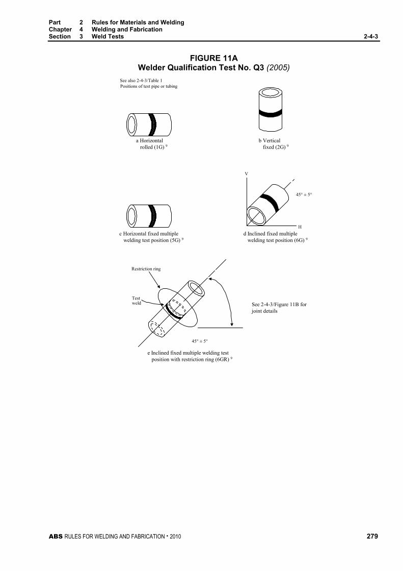
Part 2 Rules for Materials and Welding Chapter 4 Welding and Fabrication Section 3 Weld Tests 2-4-3
ABS RULES FOR WELDING AND FABRICATION . 2010 279
FIGURE 11A Welder Qualification Test No. Q3 (2005)
See also 2-4-3/Table 1Positions of test pipe or tubing
Restriction ring
Testweld
H
V
45° ± 5°
45° ± 5°
a Horizontal rolled (1G) 9
b Vertical fixed (2G) 9
c Horizontal fixed multiple welding test position (5G) 9
d Inclined fixed multiple welding test position (6G) 9
e Inclined fixed multiple welding test position with restriction ring (6GR) 9
See 2-4-3/Figure 11B forjoint details

Part 2 Rules for Materials and Welding Chapter 4 Welding and Fabrication Section 3 Weld Tests 2-4-3
280 ABS RULES FOR WELDING AND FABRICATION . 2010
FIGURE 11B Welder Qualification Test No. Q3 – 6GR
Positions of test pipe or tubing
Restriction ring
12.5mm(1/2in. max.)
37-1/2°
12.5mm(1/2 in. min.)
Macrospecimen(optional)
location of test specimens
38 mm(1 1/2 in.)
45° (Face bend)10
38 mm(1 1/2 in.)
4.8 mm(3/16 in. min.)
150 mm(6 in. min.)
12.5 mm(1/2 in. max.)3.2 mm
(1/8 in.)
12.5 mm(1/2 in. min.)
f Joint detail-restriction ring assembly
1.6 m
m(1/
16 in
.)
315° (Root bend)10 10(Face bend) 225°
10(Root bend) 135°
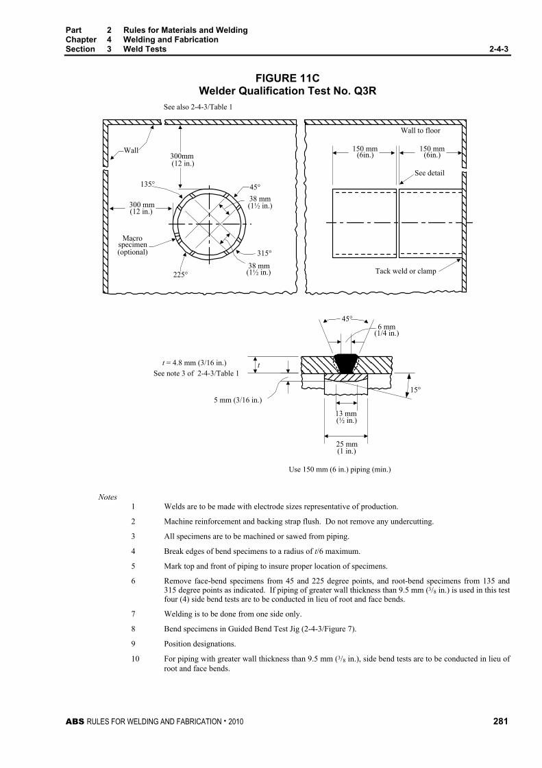
Part 2 Rules for Materials and Welding Chapter 4 Welding and Fabrication Section 3 Weld Tests 2-4-3
ABS RULES FOR WELDING AND FABRICATION . 2010 281
FIGURE 11C Welder Qualification Test No. Q3R
Use 150 mm (6 in.) piping (min.)
See note 3 of 2-4-3/Table 1
See also 2-4-3/Table 1
150 mm(6in.)
t = 4.8 mm (3/16 in.)
5 mm (3/16 in.)
25 mm(1 in.)
(½ in.)13 mm
6 mm
(1½ in.)
(1/4 in.)
15°
(optional)specimen
Macro
225°
300 mm(12 in.)
135°
(12 in.)
38 mm315°
Wall to floor
See detail
Tack weld or clamp
45°38 mm(1½ in.)
Wall
t
300mm
45°
150 mm(6in.)
Notes 1 Welds are to be made with electrode sizes representative of production.
2 Machine reinforcement and backing strap flush. Do not remove any undercutting.
3 All specimens are to be machined or sawed from piping.
4 Break edges of bend specimens to a radius of t/6 maximum.
5 Mark top and front of piping to insure proper location of specimens.
6 Remove face-bend specimens from 45 and 225 degree points, and root-bend specimens from 135 and 315 degree points as indicated. If piping of greater wall thickness than 9.5 mm (3/8 in.) is used in this test four (4) side bend tests are to be conducted in lieu of root and face bends.
7 Welding is to be done from one side only.
8 Bend specimens in Guided Bend Test Jig (2-4-3/Figure 7).
9 Position designations.
10 For piping with greater wall thickness than 9.5 mm (3/8 in.), side bend tests are to be conducted in lieu of root and face bends.

Part 2 Rules for Materials and Welding Chapter 4 Welding and Fabrication Section 3 Weld Tests 2-4-3
282 ABS RULES FOR WELDING AND FABRICATION . 2010
FIGURE 12 Welder Qualification Test No. Q4
Tack Welders for Hull Construction (See 2-4-4/5.11 - applicable for pipe welding.)
Method of rupturing specimen
(1/2 in.)
(1/2 in.)
(2 in.)
12.5 mm(1/2 in.)
Applied force
12.5 mm
100 mm (4 in.)
12.5 mm
100
mm
(4
in)
50 mm
100 mm (4 in)
Notes
1 3.2 mm (1/8 in.) diameter electrodes are to be used to make a 6.4 mm (1/4 in.) maximum size tack weld.
2 Welding in the vertical position is to be welded upwards.
3 The tack weld is to present a reasonably uniform appearance and is to be free of overlap, cracks and excessive undercut. There is to be no visible surface porosity.
4 The fractured surface of the tack weld is to be free of incomplete fusion or porosity larger than 2.4 mm (3/32 in.)

Part 2 Rules for Materials and Welding Chapter 4 Welding and Fabrication Section 3 Weld Tests 2-4-3
ABS RULES FOR WELDING AND FABRICATION . 2010 283
FIGURE 13 Orientation and Location of Charpy V-notch Specimens
for Weld and Heat Affected Zone Properties (2010) 1 2 3 4
NoteSingle vee
Double veeNote
Unbeveled
NoteSpecimen
Specimen
Specimen Lc
1st Welded side
2nd Welded side
Notch location 1 of weld2 Fusion line (weld interface)3 HAZ, 2 mm from fusion line4 HAZ, 5 mm from fusion line
1 mm (0.039 in.) min.
1 mm (0.039 in.) min.
1 mm (0.039 in.) min.
1 2 3 4
Lc
Lc
1 2 3 4
Lc
The largest size Charpy specimens possible for the material thickness are to be machined with the center of the specimen located as near as practicable to a point midway between the surface and the center of the thickness. In all cases, the distance from the surface of the material to the edge of the specimen should be approximately 1 mm (0.039 in.) or greater. For double-vee butt welds, specimens are to be machined closer to the surface of the second welded side.

284 ABS RULES FOR WELDING AND FABRICATION . 2010
P A R T S e c t i o n 4 : P i p i n g
2 C H A P T E R 4 Welding and Fabrication
S E C T I O N 4 Piping (2002)
* Note: This Section is applicable only to piping for installation on vessels to be built in accordance with the ABS Rules for Building and Classing Steel Vessels (SVR) and the ABS Guide for Building and Classing High Speed Naval Craft (HSNC). Piping intended for all other applications is to comply with Section 2-4-2.
1 General
1.1 Application The provisions of this section are intended for welding of steel pipes in systems covered in Part 4, Chapter 6 of the Rules for Building and Classing Steel Vessels, (SVR). Additional provisions, as may be specified for piping systems of specialized carriers in Part 5C of the Rules for Building and Classing Steel Vessels, where applicable, are also to be complied with. Consideration will be given to compliance with a recognized national or international welding standard that is considered equally effective.
1.3 Pipe Classes Pipe classes are as defined in 4-6-1/Table 1, (SVR). Classes I and II pipes are to comply with all the provisions of this Section. Class III pipes are to comply at least with 2-4-4/1.7, 2-4-4/3, 2-4-4/5 and 2-4-4/11.1 of this Section.
1.5 Materials For purpose of determining welding requirements, steel pipe materials are grouped as follows:
Representative Standards (1) Material Group Description
ABS Grade ASTM Grade
C and C/Mn Carbon; carbon manganese
1, 2, 3, 4, 5; 8, 9
A53, A106; A135
0.5 Mo 0.5 Mo/0.5 Cr
Up to 0.5% Molybdenum; 0.5% Molybdenum & 0.5% Chromium
6; 7 A335 P1; A335 P2
1Cr/0.5Mo 1.0 - 1.25% Chromium & 0.5% Molybdenum 11; 12
A335 P11; A335 P12
2.25Cr/1Mo 2.25% Chromium and 1.0% Molybdenum 13 A335 P22
1 Other materials complying with recognized national or international standards are also acceptable.

Part 2 Rules for Materials and Welding Chapter 4 Welding and Fabrication Section 4 Piping 2-4-4
ABS RULES FOR WELDING AND FABRICATION . 2010 285
1.7 Welding Filler Metals All welding filler metals are to be certified by their manufacturers as complying with appropriate recognized national or international standards. Welding filler metals tested, certified and listed by the Bureau in its publication Approved Welding Consumables for meeting such a standard may be used in all cases. See Part 2, Appendix 2 for approval of filler metals. Welding filler metals not so listed may also be accepted provided that:
• They are of the same type as that proven in qualifying the welding procedure; and
• They are of a make acceptable to the surveyor; and
• For welding of Class I piping, representative production test pieces are to be taken to prove the mechanical properties of the weld metal.
3 Welding Procedures and Welders
3.1 Welding Procedures Before proceeding with welding, the responsible fabricator is to prove to the satisfaction of the Surveyor that the intended welding process, welding filler metal, preheat, post weld heat treatment, etc., as applicable, have been qualified for joining the base metal. In general, the intended welding procedure is to be supported by a welding procedure qualification record (PQR) conducted in the presence of the Surveyor. Properly documented PQR, certified by a recognized body may be submitted to the Surveyor for acceptance. The PQR is to be conducted in accordance with a recognized standard, such as the ASME Boiler and Pressure Vessel Code, Section IX. The PQR may be used to support those welding procedures whose welding variables (e.g., base metal thickness, welding current, etc.) are within the ranges defined in the recognized welding standard being used.
3.3 Welders and Welding Operators Before proceeding with welding, the responsible fabricator is to prove to the satisfaction of the Surveyor that the welder or the welding operator is qualified in performing the intended welding procedure. In general, welders and welding operators are to be qualified in accordance with 2-4-3/11 in the presence of the Surveyor. Properly documented welder performance qualification records (WPQ) conducted in accordance with a recognized welding standard being used (such as the ASME Boiler and Pressure Vessel Code, Section IX) and certified by a recognized body may be presented to the Surveyor for acceptance as evidence of qualification. Once deemed qualified, the welder or the welding operator is permitted to perform the welding as qualified, as well as other welding, provided the welding variables (e.g., position, with or without backing, pipe size, etc.) of such welding are within specified ranges defined by the recognized welding standard being used.
5 Types of Welded Joints
5.1 Full Penetration Butt Joints 5.1.1 General
Full penetration butt joints for pipes are to have welds deposited on properly prepared single vee, double vee or other suitable types of grooves, with or without backing rings. The edge preparation and fit-up tolerances are to be as indicated in 2-4-4/5.1.2 and 2-4-4/5.1.3. Joints welded without backing rings are to assure complete root penetration and fusion by employing qualified welding procedures and a qualified welder demonstrating that successful joints can be achieved. All full penetration butt joints in Classes I and II piping systems are subject to radiographic examination or equivalent to the extent as indicated in 2-4-4/11 to assure that complete root penetration is achieved and the welds do not contain unacceptable imperfection.

Part 2 Rules for Materials and Welding Chapter 4 Welding and Fabrication Section 4 Piping 2-4-4
286 ABS RULES FOR WELDING AND FABRICATION . 2010
5.1.2 Edge Preparation Dimensions of the edge-preparation are to be in accordance with recognized standards or that used in the welding procedure qualified by the responsible fabricator. The preparation of the edges shall preferably be carried out by mechanical means. When flame cutting is used, care should be taken to remove the oxide scales and any notch due to irregular cutting by matching grinding or chipping back to sound metal.
5.1.3 Alignment and Fit-up For pipes to be butt-welded, the alignment of the pipes at the prepared edge is to be within the following maximum offsets:
i) Pipes of all diameters and thickness welded with permanently fitted backing ring: 0.5 mm (0.02 in.).
ii) Pipes welded without fitted backing ring:
Nominal pipe size, d
Pipe wall thickness, t
Alignment Tolerance
d ≤ 150 mm (6 in.) or t ≤ 6.0 mm (0.24 in.) lesser of 1.0 mm (0.04 in.) or t/4
150 mm (6 in.) < d ≤ 300 mm (12 in.) or 6.0 mm (0.24 in.) < t
≤ 9.5 mm (0.37 in.) lesser of 1.5 mm (0.06 in.) or t/4
d > 300 mm (12 in.) or t > 9.5 mm (0.37 in.) lesser of 2.0 mm (0.08 in.) or t/4
Where pipes of different thicknesses are to be butt welded, and if the difference in thickness is more than 1/4 thickness of the thinner section or 3 mm (1/8 in.), whichever is less, a taper transition having a length not less than three times the offset between the abutting sections is to be provided at the joint.
5.3 Square-groove Butt Joint Square groove butt joints may be used in Class III piping systems for low pressure systems which are open to atmosphere, such as tank vent and overflow pipes. In general, such joints should not be made on pipes having wall thickness greater than 4.8 mm (3/16 in.).
5.5 Fillet-welded Joints 5.5.1 Socket Welded Joints
Socket welded joints employing sockets complying with recognized standards are to be welded using single fillet weld with leg size not less than 1.1 times the nominal thickness of the pipe. See also 4-6-2/5.5.2 (SVR) for limitation of its use and 4-6-2/Figure 1 (SVR) for fit up details.
5.5.2 Slip-on Welded Sleeves Joints Sleeves meeting dimensional and fit-up requirements in 4-6-2/5.5.3 (SVR) and 4-6-2/Figure 1 (SVR) may be used for joining pipes with limitations as indicated therein. The fillet weld attaching the sleeve to the pipe is to have a leg size not less than 1.1 times the nominal thickness of the pipe.
5.7 Flange Attachment Welds (2009) A weld neck flange is to be welded to the pipe with a full penetration butt weld conforming to 2-4-4/5.1. Slip-on welded flange and socket welded flange are to be attached to pipes with double fillet and single fillet welds respectively. The external fillet weld is to have a leg size not less than 1.1 times the nominal thickness of the pipe or thickness of the hub, whichever is less. For class II and Class III flange joints, the size of the external fillet weld need not exceed 13 mm (0.531 in.) maximum. The internal weld for a slip-on welded flange is to have a leg size not less than the smaller of 6.0 mm (1/4 in.) or the nominal thickness of the pipe.

Part 2 Rules for Materials and Welding Chapter 4 Welding and Fabrication Section 4 Piping 2-4-4
ABS RULES FOR WELDING AND FABRICATION . 2010 287
5.9 Branch Connections Pipe branches made by welding branch pipe to a hole cut in the run pipe are to be designed in accordance with 4-6-2/5.3 (SVR). In general, the attachment weld is to be a full penetration groove weld through the thickness of the run pipe or of the branch pipe, with ample finished fillet weld.
5.11 Tack Welding Tack welds, where used, are to be made with filler metal suitable for the base metal. Tack welds intended to be left in place and form part of the finished weld are to be made by qualified pipe welders using process and filler metal the same as or equivalent to the welding procedure to be used for the first pass. When preheating is required by 2-4-4/7, the same preheating should be applied prior to tack welding.
5.13 Brazing (2005) When brazed pipe joints are tested in tension, the joint strength is not to be less than the tensile strength of the pipe material.
7 Preheat In general, dryness is to be assured before welding; this may be achieved with suitable preheating, as necessary. Where ambient temperatures are below 10°C (50°F), for Classes I and II pipes, the welded parts are to be heated, prior to welding, to at least 10°C (50°F). In addition, preheating is required depending on base metal thickness and chemical composition as indicated in the following table. The values given in the table below are based on the use of low hydrogen processes; consideration is to be given to using higher preheating temperatures when low hydrogen processes are not used. Consideration will be given to alternative preheat requirements based on a recognized standard and welding procedure qualification conducted thereto.
Material Group Thickness of the Thicker Joining Base Metal
Minimum Preheat Temperature
C and C/Mn C + Mn/6 ≤ 0.4 ≥ 20 mm (0.79 in.) 50°C (122°F) C + Mn/6 > 0.4 ≥ 20 mm (0.79 in.) 100°C (212°F) 0.5 Mo 0.5 Mo/0.5 Cr
> 13 mm (0.51 in.) 100°C (212°F)
1Cr/0.5Mo < 13 mm (0.51 in.) 100°C (212°F) ≥ 13 mm (0.51 in.) 150°C (302°F) 2.25Cr/1Mo < 13 mm (0.51 in.) 150°C (302°F) ≥ 13 mm (0.51 in.) 200°C (392°F)
9 Post-weld Heat Treatment
9.1 Procedure Post-weld heat treatments are to be conducted according to a procedure acceptable to the Surveyor. They can be carried out in furnaces or locally. Where conducted locally, the weld is to be heated in a circumferential band around the pipe having a width of at least three times the wall thickness. For fabricated branch connections, the band is to extend at least two times the run pipe wall thickness beyond the branch weld. Suitable temperature and time recording equipment is to be provided.
The welded joint is to be heated slowly and uniformly to a temperature within the range indicated in the table in 2-4-4/9.3 and soaked at this temperature for a period of 1 hour per 25 mm (1 in.) of thickness, with a minimum of half an hour. Thereafter, it is to be cooled slowly and uniformly in the furnace or under insulation to a temperature not more than 400°C and subsequently cooled in a still atmosphere.
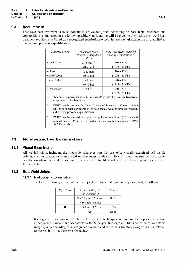
Part 2 Rules for Materials and Welding Chapter 4 Welding and Fabrication Section 4 Piping 2-4-4
288 ABS RULES FOR WELDING AND FABRICATION . 2010
9.3 Requirement Post-weld heat treatment is to be conducted on welded joints depending on base metal thickness and compositions as indicated in the following table. Consideration will be given to alternative post-weld heat treatment requirements based on a recognized standard, provided that such requirements are also applied to the welding procedure qualification.
Material Group Thickness of the Thicker Joining Base
Metal
Post-weld Heat Treatment Soaking Temperature (1)
C and C/Mn ≥ 15 mm (2) (0.59 in.)
550–620°C (1022–1148°F)
0.5Mo 0.5Mo/0.5Cr
≥ 15 mm (0.59 in.)
580–640°C (1076–1184°F)
1 Cr/0.5Mo > 8 mm (0.32 in.)
620–680°C (1148–1256°F)
2.25Cr/1Mo All (3) 650–720°C (1202–1328°F)
1 Maximum temperature is to be at least 20°C (65°F) below the tempering temperature of the base metal.
2 PWHT may be omitted for Class III pipes of thickness ≤ 30 mm (1.2 in.) subject to special consideration of base metal, welding process, preheat, and welding procedure qualification.
3 PWHT may be omitted for pipes having thickness ≤ 8 mm (0.31 in.) and nominal size ≤ 100 mm (4 in.) and with a service temperature of 450°C (842°F) and above.
11 Nondestructive Examination
11.1 Visual Examination All welded joints, including the root side, wherever possible, are to be visually examined. All visible defects, such as cracks, excessive weld reinforcement, undercuts, lack of fusion on surface, incomplete penetration where the inside is accessible, deficient size for fillet welds, etc. are to be repaired, as provided for in 2-4-4/13.
11.3 Butt Weld Joints 11.3.1 Radiographic Examination
11.3.1(a) Extent of Examination. Butt joints are to be radiographically examined, as follows:
Pipe Class Nominal Size, d / wall thickness, t
Extent
I D > 65 mm (2.5 in.) or t > 9.5 mm (3/8 in.)
100%
II d > 90 mm (3.5 in.) 10% III All None
Radiographic examination is to be performed with techniques and by qualified operators meeting a recognized standard and acceptable to the Surveyor. Radiographic films are to be of acceptable image quality according to a recognized standard and are to be submitted, along with interpretation of the results, to the Surveyor for review.
Part 2 Rules for Materials and Welding Chapter 4 Welding and Fabrication Section 4 Piping 2-4-4
ABS RULES FOR WELDING AND FABRICATION . 2010 289
11.3.1(b) Acceptance Criteria. Welds shown by radiography to have any of the following types of imperfections are to be judged unacceptable and are to be repaired, as provided in 2-4-4/13.
i) Any type of crack, or zones of incomplete fusion or penetration.
ii) Any elongated slag inclusion which has length greater than
6.0 mm (1/4 in.) for t ≤ 19.0 mm (3/4 in.),
t/3 for 19.0 mm (3/4 in.) < t ≤ 57.0 mm (21/4 in.)
19.0 mm (3/4 in.) for t > 57.0 mm (21/4 in.)
where t is the thickness of the thinner portion of the weld.
iii) Rounded indications in excess of an acceptance standard, such as ASME Boiler and Pressure Vessel Code, Section VIII, Div. 1.
11.3.1(c) Re-examination. If the radiograph disclosed unacceptable imperfections, the weld is to be repaired and thereafter re-examined by radiography. For Class II pipe joints subjected to 10% radiographic examination only, if unacceptable imperfections were disclosed to such an extent that quality of welds is in doubt, more joints are to be examined at the discretion of the Surveyor.
11.3.2 Ultrasonic Examination Ultrasonic examination may be used in lieu of radiographic examination required by 2-4-4/11.3.1. Such examination technique is to be conducted in accordance with procedures and by qualified operators meeting a recognized standard and acceptable to the Surveyor.
11.5 Fillet Weld Joints In Class I piping, all fillet welds attaching pipes to flanges, sockets, slip-on sleeves, pipe branches, etc. are to be examined by the magnetic particle method or other appropriate nondestructive methods. All surfaces examined and found to have any of the following indications are to be repaired.
• Crack or relevant linear indication (having a length greater than three times the width);
• Relevant rounded indication (circular or elliptical shape with a length equal to or less than three times its width) greater than 5 mm (3/16 in.); or
• Four or more relevant rounded indications in a line separated by 2.0 mm (1/16 in.) or less, edge to edge.
13 Weld Repair Any weld joint imperfection disclosed by examination in 2-4-4/11 and deemed unacceptable is to be removed by mechanical means or thermal gouging processes, after which the joint is to be welded using the appropriate qualified welding procedure by a qualified welder. Preheat and post-weld heat treatment is to be performed as indicated in 2-4-4/7 and 2-4-4/9, as applicable. Upon completion of repair, the repaired weld is to be re-examined by the appropriate technique that disclosed the defect in the original weld.
15 Pipe Forming and Bending
15.1 Cold Forming Where pipe is cold bent to a mean bending radius of less than or equal to four times the outside diameter of the pipe, it is to be subjected to a stress relieving heat treatment at least equivalent to that specified in 2-4-4/9.3, except for C and C/Mn steels with ultimate tensile strength of 410 MPa (42 kgf/mm2, 60,000 psi) or less.
15.3 Hot Forming Hot forming is to be carried out in the temperature range 850–1000°C for all material groups; however, the temperature may decrease to 750°C during the forming process. When hot forming is carried out within this temperature range, no stress relieving heat treatment is required for C, C/Mn, 0.5Mo, 0.5Mo/0.5Cr material groups, while stress relieving heat treatment equivalent to that specified in 2-4-4/9.3 is required for 1Cr/0.5Mo and 2.25Cr/1Mo material groups.
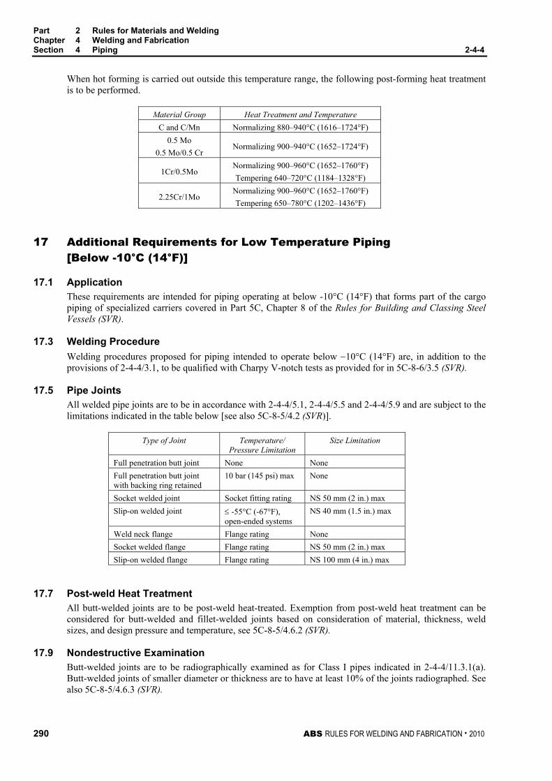
Part 2 Rules for Materials and Welding Chapter 4 Welding and Fabrication Section 4 Piping 2-4-4
290 ABS RULES FOR WELDING AND FABRICATION . 2010
When hot forming is carried out outside this temperature range, the following post-forming heat treatment is to be performed.
Material Group Heat Treatment and Temperature C and C/Mn Normalizing 880–940°C (1616–1724°F)
0.5 Mo 0.5 Mo/0.5 Cr
Normalizing 900–940°C (1652–1724°F)
1Cr/0.5Mo Normalizing 900–960°C (1652–1760°F) Tempering 640–720°C (1184–1328°F)
2.25Cr/1Mo Normalizing 900–960°C (1652–1760°F) Tempering 650–780°C (1202–1436°F)
17 Additional Requirements for Low Temperature Piping [Below -10°C (14°F)]
17.1 Application These requirements are intended for piping operating at below -10°C (14°F) that forms part of the cargo piping of specialized carriers covered in Part 5C, Chapter 8 of the Rules for Building and Classing Steel Vessels (SVR).
17.3 Welding Procedure Welding procedures proposed for piping intended to operate below −10°C (14°F) are, in addition to the provisions of 2-4-4/3.1, to be qualified with Charpy V-notch tests as provided for in 5C-8-6/3.5 (SVR).
17.5 Pipe Joints All welded pipe joints are to be in accordance with 2-4-4/5.1, 2-4-4/5.5 and 2-4-4/5.9 and are subject to the limitations indicated in the table below [see also 5C-8-5/4.2 (SVR)].
Type of Joint Temperature/ Pressure Limitation
Size Limitation
Full penetration butt joint None None Full penetration butt joint with backing ring retained
10 bar (145 psi) max None
Socket welded joint Socket fitting rating NS 50 mm (2 in.) max Slip-on welded joint ≤ -55°C (-67°F),
open-ended systems NS 40 mm (1.5 in.) max
Weld neck flange Flange rating None Socket welded flange Flange rating NS 50 mm (2 in.) max Slip-on welded flange Flange rating NS 100 mm (4 in.) max
17.7 Post-weld Heat Treatment All butt-welded joints are to be post-weld heat-treated. Exemption from post-weld heat treatment can be considered for butt-welded and fillet-welded joints based on consideration of material, thickness, weld sizes, and design pressure and temperature, see 5C-8-5/4.6.2 (SVR).
17.9 Nondestructive Examination Butt-welded joints are to be radiographically examined as for Class I pipes indicated in 2-4-4/11.3.1(a). Butt-welded joints of smaller diameter or thickness are to have at least 10% of the joints radiographed. See also 5C-8-5/4.6.3 (SVR).

ABS RULES FOR TESTING AND CERTIFICATION OF MATERIALS . 2010 291
P A R T Appendix 1: List of Destructive and Nondestructive Tests Required in Part 2, Chapters 1, 2 and 3, and Responsibility for Verifying
2 Rules for Testing and Certification of Materials
A P P E N D I X 1 List of Destructive and Nondestructive Tests Required in Part 2, Chapters 1, 2 and 3, and Responsibility for Verifying
Test and Test Data i) Witnessed Tests. The designation (W) indicates that the Surveyor is to witness the testing unless
the plant and product is approved under the Bureau’s Quality Assurance Program.
ii) Manufacturer’s Data. The designation (M) indicates that test data is to be provided by the manufacturer without verification by a Surveyor of the procedures used or the results obtained.
iii) Other Tests. The designation (A) indicates those tests for which test data is to be provided by the supplier and audited by the Surveyor to verify that the procedures used and random tests witnessed are in compliance with Rule requirements.
2-1-1 General 2-1-1/17 Through Thickness Properties (W) 2-1-2 Ordinary-Strength Hull Structural Steel 2-1-2/5.1 Ladle Analysis (M) 2-1-2/5.3 Product Analysis (M) 2-1-2/5.7.1 McQuaid-Ehn (M) 2-1-2/9.1 Tension Test (W) 2-1-2/11.1 Charpy V-notch Impact Test (W) 2-1-3/1 Higher-Strength Hull Structural Steel 2-1-3/3 Ladle Analysis (M) 2-1-3/3 Tension Test (W) 2-1-3/3 Charpy V-notch Impact Test (W) 2-1-3/3 Product Analysis (M) 2-1-3/5 McQuaid-Ehn (M) 2-1-4 Materials for Low Temperature Service 2-1-4/5.1 Charpy V-notch Impact Test (W) 2-1-4/5.3 Drop-weight Test (NDTT) (W) 2-1-5 Hull Steel Castings 2-1-5/7 Tension Test (W) 2-1-5/13.11 Magnetic Particle Inspection (A) 2-1-5/13.11 Dye Penetrant Inspection (A) 2-1-5/13.11 Ultrasonic Inspection (A) 2-1-6 Hull Steel Forgings 2-1-6/1.7 Ladle Analysis (M) 2-1-6/7 Tension Test (W) 2-1-6/11.3 Brinell Hardness Test (BHN) (W)

Part 2 Rules for Materials and Welding Appendix 1 List of Destructive and Nondestructive Tests Required in Part 2, Chapters 1, 2
and 3, and Responsibility for Verifying 2-A1
292 ABS RULES FOR TESTING AND CERTIFICATION OF MATERIALS . 2010
2-2-1 Anchors 2-2-1/7.1 Proof Test (W) 2-2-1/7.3 Product Test (W) – See 2-2-1/Tables 1 & 2 2-2-2 Anchor Chain 2-2-2/11.3 Ladle Analysis (M) 2-2-2/13.5, 2-2-2/19.5 and 2-2-2/23.3 Tension Test (W) 2-2-2/13.7 and 2-2-2/23.3 Bend Test (W) 2-2-2/13.9, 2-2-2/19.5 and 2-2-2/23.3 Charpy V-notch Impact Test (W) 2-2-2/17.1, 2-2-2/19.1 and 2-2-2/23.13 Breaking Test (W) 2-2-2/17.1, 2-2-2/19.3 and 2-2-2/23.15 Proof Test (W) 2-2-2/23.9 Magnetic Particle Inspection (A) 2-2-2/23.11 Brinell Hardness Test (W) 2-2-2/25 Unstudded Short-link Chain 2-2-2/25.1 Ladle Analysis (M) 2-2-2/25.1 Tension Test (W) 2-2-2/25.1 Bend Test (W) 2-2-2/25.3 Breaking Test (W) 2-2-2/25.3 Proof Test (W) 2-3-2 General Requirements for All Grades of Steel Plates for Machinery, Boilers, and Pressure Vessels 2-3-2/1.7.1 Ladle Analysis (M) 2-3-2/1.7.2 Product Analysis (M) 2-3-2/1.9.1, 2-3-2/1.9.2, and 2-3-2/1.9.3 Test Specimens (W) 2-3-2/1.11.1, 2-3-2/1.11.2, and 2-3-2/1.11.3 Tensile Properties (W) 2-3-2/3 Steel Plates for Intermediate Temperature Service 2-3-2/3.5 Chemical Composition (M) 2-3-2/3.9 Tensile Properties (W) 2-3-2/5 Steel Plates for Intermediate and Higher-Temperature Service 2-3-2/5.7 Chemical Composition (M) 2-3-2/5.11 Tensile Properties (W) 2-3-2/7 Steel Plates for Intermediate and Lower-Temperature Service 2-3-2/7.1 McQuaid-Ehn (M) 2-3-2/7.7 Chemical Composition (M) 2-3-2/7.11 Tensile Properties (W) 2-3-2/9 Materials for Low Temperature Service [Below -18°C (0°F)] Those listed in Section 2-1-4 and 2-3-2/9 2-3-3 Seamless Forged-Steel Drums 2-3-3/1 Tension Tests (W) 2-3-4 Seamless-Steel Pressure Vessels 2-3-4/3 Tension Test (W) 2-3-4/5 Flattening Test (W) 2-3-4/7 Hydrostatic Test (W) 2-3-4/9 Thickness Test (W)

Part 2 Rules for Materials and Welding Appendix 1 List of Destructive and Nondestructive Tests Required in Part 2, Chapters 1, 2
and 3, and Responsibility for Verifying 2-A1
ABS RULES FOR TESTING AND CERTIFICATION OF MATERIALS . 2010 293
2-3-5 Boiler and Superheater Tubes 2-3-5/9 Chemical Composition (M) 2-3-5/11 Product Analysis (M) 2-3-5/17 Tensile Properties (W) 2-3-5/19 Flattening Test (W) 2-3-5/21 Reverse Flattening Test (W) 2-3-5/23 Flange Test (W) 2-3-5/25 Flaring Test (W) 2-3-5/27 Crush Test (W) 2-3-5/29 Hardness Test (W) 2-3-5/31 Hydrostatic Test (W) 2-3-5/33 Nondestructive Electric Test (NDET) (A) 2-3-5/39 Thickness Test (A) 2-3-6 Boiler Rivet and Staybolt Steel and Rivets 2-3-6/5 Tensile Properties (W) 2-3-6/7 Bending Properties (Bars) (W) 2-3-6/13.1 Bending Properties (Rivets) (W) 2-3-6/13.3 Flattening Test (W) 2-3-7 Steel Machinery Forgings 2-3-7/1.1.2, 2-3-7/3.1.2, 2-3-7/5.1.2, 2-3-7/7.1.2
Chemical Composition (M)
2-3-7/1.7, 2-3-7/3.7, 2-3-7/5.7, 2-3-7/7.7 Tensile Properties (W) 2-3-7/1.13.1, 2-3-7/5.11.1 Surface Inspection of Tailshaft Forgings (W) 2-3-7/1.13.2, 2-3-7/5.11.2 Ultrasonic Examination of Tail Shaft Forgings (A) 2-3-7/1.11.2, 2-3-7/3.7.2, 2-3-7/5.9.4, 2-3-7/7.7.2
Hardness Test (W)
2-3-8 Hot-rolled Steel Bars for Machinery 2-3-8/1 Those listed in Section 2-3-7 above 2-3-9 Steel Castings for Machinery, Boilers, and Pressure Vessels 2-3-9/1.3 Chemical Composition (M) 2-3-9/7 Tensile Properties (W) 2-3-9/15.7 Magnetic Particle or Dye Penetrant Inspection (W) 2-3-10 Ductile (Nodular) Iron Castings 2-3-10/11 Tension Tests (W) 2-3-10/7 Chemical Composition (M) 2-3-11 Gray-iron Castings 2-3-11/13 Tension Test (W) 2-3-12 Steel Piping 2-3-12/5 McQuaid-Ehn (M) 2-3-12/9 Chemical Composition (M) 2-3-12/13 Product Analysis (M) 2-3-12/23 Tension Tests (W) 2-3-12/25 Bend Test (W) 2-3-12/27 Flattening Test (W) 2-3-12/29 Hydrostatic Test (W) 2-3-12/37 Thickness Test (A)

Part 2 Rules for Materials and Welding Appendix 1 List of Destructive and Nondestructive Tests Required in Part 2, Chapters 1, 2
and 3, and Responsibility for Verifying 2-A1
294 ABS RULES FOR TESTING AND CERTIFICATION OF MATERIALS . 2010
2-3-13 Piping, Valves and Fittings for Low Temperature Service [Below -18°C (0°F)] 2-3-13/5 McQuaid-Ehn (M) 2-3-13/11 Chemical Composition (M) 2-3-13/13 Mechanical Test (M) [(W) for Piping] 2-3-13/15 Impact Properties (M) [(W) for Piping] 2-3-13 Valves on Vessels Intended to Carry Liquefied Gases in Bulk for Low Temperature Service [at or Below -55°C (-67°F)] (2006) 2-3-13/5 McQuaid-Ehn (M) 2-3-13/11 Chemical Composition (M) 2-3-13/13 Mechanical Test (W) 2-3-13/15 Impact Properties (W) 2-3-13 Valves on Vessels Intended to Carry Liquefied Gases in Bulk for Low Temperature Service [Above -55°C (-67°F)] (2006) 2-3-13/5 McQuaid-Ehn (M) 2-3-13/11 Chemical Composition (M) 2-3-13/13 Mechanical Test (M) 2-3-13/15 Impact Properties (M) 2-3-14 Bronze Castings 2-3-14/3.3 Chemical Composition (M) 2-3-14/3.9 Tensile Properties (W) 2-3-14/3.21 Dye Penetrant Inspection (W) 2-3-14/5 Charpy V-notch Impact Test (W) 2-3-15 Austenitic Stainless Steel Propeller Castings 2-3-15/3 Dye Penetrant Inspection (W) 2-3-15/5 Chemical Composition (M) 2-3-15/7 Tensile Properties (W) 2-3-15/11 Charpy V-notch Impact Test (W) 2-3-16 Seamless Copper Piping 2-3-16/9 Chemical Composition (M) 2-3-16/11 Tension Test (W) 2-3-16/13 Expansion Test (W) 2-3-16/15 Flattening Test (W) 2-3-16/17 Hydrostatic Test (W) (M) 2-3-16/23 Thickness Test (A) 2-3-17 Seamless Red-brass Piping 2-3-17/7 Chemical Composition (M) 2-3-17/9 Expansion Test (W) 2-3-17/11 Flattening Test (W) 2-3-17/13 Mercurous Nitrate Test (M) 2-3-17/15 Bend Test (W) 2-3-17/17 Hydrostatic Test (W) (M) 2-3-17/23 Thickness Test (A)

ABS RULES FOR WELDING AND FABRICATION . 2010 295
P A R T A p p e n d i x 2 : R e q u i r e m e n t s f o r t h e A p p r o v a l o f F i l l e r M e t a l s
2 Rules for Welding and Fabrication
A P P E N D I X 2 Requirements for the Approval of Filler Metals
CONTENTS SECTION 1 General................................................................................................ 299
1 Scope..............................................................................................299 1.1 Condition of Approval .................................................................. 299 1.3 Approval Procedure..................................................................... 299 1.5 Aluminum Filler Metals ................................................................ 299
3 Grading ...........................................................................................299 3.1 ABS Grades ................................................................................ 299 3.3 Other Standards .......................................................................... 300 3.5 Special Properties ....................................................................... 300
5 Manufacturer’s Guarantee ..............................................................300 7 Plant Inspection ..............................................................................300
7.1 Initial Inspection........................................................................... 300 7.3 Annual Inspection........................................................................ 300
9 Test Requirements..........................................................................300 9.1 General........................................................................................300 9.3 Test Plate Material ...................................................................... 301
11 Welding Conditions .........................................................................301 13 Chemical Analysis...........................................................................302 15 Deposited Metal Tension Test ........................................................302
15.1 Specimen Type and Preparation ................................................. 302 15.3 Hydrogen Removal...................................................................... 302 15.5 Test Requirements ...................................................................... 302
17 Butt Weld Tension Test...................................................................302 17.1 Specimen Type and Preparation ................................................. 302 17.3 Test Requirements ...................................................................... 302
19 Impact Test .....................................................................................302 19.1 Specimen Type and Preparation ................................................. 302 19.3 Test Requirements ...................................................................... 302 19.5 Retest .......................................................................................... 303
21 Butt Weld Bend Test .......................................................................303 21.1 Specimen Type and Preparation ................................................. 303 21.3 Test Requirements ...................................................................... 303 21.5 Alternative Test for YQ-Grades ................................................... 303

296 ABS RULES FOR WELDING AND FABRICATION . 2010
23 Diffusible Hydrogen Test.................................................................303 23.1 Optional or Required Test............................................................303 23.3 Test Methods...............................................................................304 23.5 Alternative Test Method...............................................................304 23.7 Test Requirements ......................................................................304
25 Special Tests...................................................................................305 25.1 Nondestructive Testing ................................................................305 25.3 Additional Tests ...........................................................................305
27 Licensee Approvals.........................................................................305 29 Annual Check Tests........................................................................305
29.1 Upgrading and Uprating...............................................................305
31 Quality Assurance Program............................................................305 33 Retests ............................................................................................306 TABLE 1 Tension Test Requirements..................................................308 TABLE 2 Impact Test Requirements....................................................309 FIGURE 1 Deposited Metal Tension Test Specimen .............................306 FIGURE 2 Butt Weld Tension Test Specimen........................................306 FIGURE 3 Charpy V-Notch Impact Test Specimen................................307 FIGURE 4 Bending Elongation Test.......................................................307
SECTION 2 Electrodes for Shielded Metal Arc Welding ..................................... 310
1 General ...........................................................................................310 3 Chemical Analysis...........................................................................310 5 Deposited Metal Test Assemblies ..................................................310
5.1 Test Assembly .............................................................................310 5.3 Test Specimens...........................................................................310
7 Butt Weld Test Assemblies .............................................................310 7.1 Test Assemblies ..........................................................................310 7.3 Welding Procedure ......................................................................311 7.5 Test Specimens...........................................................................311
9 Fillet Weld Test Assemblies............................................................311 9.1 General........................................................................................311 9.3 Test Assemblies ..........................................................................311 9.5 Welding Procedure ......................................................................312 9.7 Test Specimens...........................................................................312
11 Low Hydrogen Approval..................................................................312 11.1 Ordinary-Strength Filler Metals....................................................312 11.3 Higher-Strength Filler Metals .......................................................312 11.5 YQ Grade Filler Metals ................................................................312
13 Annual Check Tests........................................................................313 13.1 General........................................................................................313 13.3 Upgrading and Uprating...............................................................313

ABS RULES FOR WELDING AND FABRICATION . 2010 297
FIGURE 1 Deposited-Metal Test Assembly for Manual and Gas-Metal Arc Welding .........................................................314
FIGURE 2 Butt-Weld Test Assembly for Manual and Gas-Metal Arc Welding...........................................................................315
FIGURE 3 Fillet-Weld Test Assembly ....................................................316 FIGURE 4 Fillet Weld Hardness Test Locations ....................................316
SECTION 3 Wire-Flux Combinations for Submerged Arc Welding.................... 317
1 General ...........................................................................................317 3 Chemical Analysis...........................................................................317 5 Deposited Metal Test Assemblies for Multi-run Technique ............317
5.1 Test Assembly............................................................................. 317 5.3 Test Specimens...........................................................................317
7 Butt Weld Test Assemblies for Multi-run Technique.......................318 7.1 Test Assembly............................................................................. 318 7.3 Test Specimens...........................................................................318
9 Butt Weld Assemblies for Two-run Technique................................318 9.1 Test Assemblies .......................................................................... 318 9.3 Test Specimens...........................................................................318 9.5 Longitudinal All-Weld-Metal Tension Test ................................... 318
11 Fillet Weld Tests .............................................................................318 13 Low Hydrogen Approval..................................................................319
13.1 YQ Grade Wires – Flux Combination .......................................... 319
15 Annual Check Tests........................................................................319 15.1 General........................................................................................319 15.3 Upgrading and Uprating ..............................................................319
17 Multiple Electrodes..........................................................................319 19 Electroslag Welding ........................................................................319
19.1 General........................................................................................319 19.3 Annual Tests ...............................................................................320 19.5 Upgrading and Uprating ..............................................................320
FIGURE 1 Deposited-Metal Test Assembly for Submerged Arc
Welding – Multi-run Technique and Automatic Gas-Metal Arc Welding .........................................................321
FIGURE 2 Butt-Weld Test Assembly for Submerged Arc Welding – Multi-run Technique ..............................................................322
FIGURE 3 Butt-Weld Test Assembly for Submerged Arc Welding – Two-run Technique ...............................................................323
FIGURE 4 Butt-Weld Impact Specimen Location for Submerged and Gas-Metal Arc Welding – Two-run Technique...............324

298 ABS RULES FOR WELDING AND FABRICATION . 2010
SECTION 4 Wire and Wire Gas Combinations for Gas Metal Arc Welding and Flux Cored Wires for Flux Cored Arc Welding ......................... 325 1 General ...........................................................................................325 3 Chemical Analysis and Shielding Gas Compositions .....................325 5 Deposited Metal Test Assemblies for Semi-automatic and
Automatic Testing ...........................................................................326 5.1 Semi-automatic Test Assemblies.................................................326 5.3 Test Specimens for Semi-automatic ............................................326 5.5 Automatic Test Assembly ............................................................326 5.7 Test Specimens for Automatic .....................................................326
7 Butt Weld Test Assemblies for Semi-automatic and Automatic Techniques......................................................................................327 7.1 Test Assemblies ..........................................................................327 7.3 Welding Procedure ......................................................................327 7.5 Test Specimens...........................................................................327
9 Butt Weld Test Assemblies for Two-run Technique .......................327 9.1 Test Assemblies ..........................................................................327 9.3 Test Specimens...........................................................................327 9.5 Longitudinal All-Weld-Metal Tension Test ...................................328
11 Fillet Weld Tests .............................................................................328 11.1 General........................................................................................328 11.3 Test Assemblies ..........................................................................328 11.5 Welding Procedure ......................................................................328 11.7 Test Requirements ......................................................................328
13 Low Hydrogen Approval..................................................................328 13.1 Flux Cored Wire...........................................................................328
15 Annual Check Tests........................................................................329 15.1 General........................................................................................329 15.3 Upgrading and Uprating...............................................................329
17 Electrogas Welding .........................................................................329 17.1 General........................................................................................329 17.3 Annual Tests................................................................................330 17.5 Upgrading and Uprating...............................................................330
TABLE 1 Compositional Limits of Designated Groups of Gas Types
and Mixtures..........................................................................326 FIGURE 1 Butt-Weld Test Assembly for Gas-Metal Arc Welding –
Two-run Technique ...............................................................331 FIGURE 2 Contact Tip to Work Distance ...............................................332

ABS RULES FOR WELDING AND FABRICATION . 2010 299
P A R T S e c t i o n 1 : G e n e r a l
2 A P P E N D I X 2 Requirements for the Approval of Filler Metals
S E C T I O N 1 General
1 Scope
1.1 Condition of Approval The scope and conditions of classification contained in Part 1, Chapter 1 of the ABS Rules for Building and Classing Steel Vessels are applicable to the approval of welding filler metals, insofar as they are appropriate. Approval will be for each plant of each manufacturer carrying out its own quality control inspection and certification.
1.3 Approval Procedure (1 October 1993) Welding filler metals intended for hull construction will be approved by ABS, subject to compliance with the requirements and test schedules as outlined herein. The requirements are based on the following:
1.3.1 Guarantee by the manufacturer of the minimum properties
1.3.2 Inspection of the manufacturing facility by an ABS Surveyor
1.3.3 Testing of selected samples
The test assemblies are to be prepared and tested in the presence of an ABS Surveyor. The Surveyor is to be satisfied that the manufacturer’s plant and method of filler metal production are capable of ensuring reasonable uniformity in production. The Bureau is to be notified of any alterations proposed to be made in the production of filler metals.
1.5 Aluminum Filler Metals Approval of aluminum filler metals is covered in Appendix 2-5-A2 of the ABS Rules for Materials and Welding – Aluminum and Fiber Reinforced Plastics (FRP).
3 Grading
3.1 ABS Grades (1997) Filler metals are divided into three groups based on the steel for which they are intended.
Ordinary-Strength Steel No suffix. (2-1-2/Table 1 through 2-1-2/Table 4)
Higher-Strength Steel Suffix Y and Y400 (2-1-3/Table 1 through 2-1-3/Table 4)
Quenched and Tempered Steel Suffix YQ420 through YQ690 (MODU Rules 3-1-A3/Tables 1 and 2)
Each group is further divided into multiple levels based on the strength and/or toughness, the latter being represented by the toughness digit 1 through 5. Exact combination of digit/suffix and corresponding tensile and impact requirements are indicated in 2-A2-1/Table 1 and 2-A2-1/Table 2.

Part 2 Rules for Materials and Welding Appendix 2 Requirements for the Approval of Filler Metals Section 1 General 2-A2-1
300 ABS RULES FOR WELDING AND FABRICATION . 2010
3.3 Other Standards At the option of the manufacturer, filler metals may be approved to a recognized standard. The required tests and procedures for such approval are to be in accordance with the specified standard. In addition, annual inspection and testing are to be carried out for continued approval.
3.5 Special Properties Welding filler metals may be approved to the manufacturer’s guaranteed minimum properties over and above or in addition to the requirements for the applicable standard. Notations indicating guaranteed minimum properties will be added, as appropriate, upon verification by test.
5 Manufacturer’s Guarantee (1 October 1994) Each plant of the manufacturer is to file an application for each filler metal indicating the following:
• Specification and Grade/Classification
• Electrode (wire) size and welding position
• Flux or shielding gas
• Current/Polarity
• Recommended volts and amperage
• Guaranteed all-weld-metal chemical and mechanical properties
• Guaranteed hydrogen content (for H15, H10, H5, Y or Y400 designation)
7 Plant Inspection
7.1 Initial Inspection Before marketing the product, each plant manufacturing welding filler metals submitted for ABS approval is to be inspected by an ABS Surveyor to satisfy himself that the facilities, production method, quality assurance procedures, etc., in that plant are adequate to maintain uniform and acceptable quality in production.
The Surveyor is also to satisfy himself that the testing machines are maintained in an accurate condition and that a record of periodical calibration is maintained up to date.
Where a plant approved by ABS intends to commence production of a new product, plant inspection may be required for the facilities, production methods, and quality control procedures for the new product.
7.3 Annual Inspection (1 October 1993) Each plant manufacturing ABS-approved welding filler metals is to be inspected by an ABS Surveyor at an interval of approximately 12 months. The extent of the inspection is as indicated in 2-A2-1/7.1.
9 Test Requirements
9.1 General When the plant inspection required in 2-A2-1/7 is completed, representative filler metal samples will be selected by the Surveyor for welding and testing in his presence. The preparation of the test assemblies and test specimens are to be in accordance with the following:

Part 2 Rules for Materials and Welding Appendix 2 Requirements for the Approval of Filler Metals Section 1 General 2-A2-1
ABS RULES FOR WELDING AND FABRICATION . 2010 301
9.3 Test Plate Material 9.3.1 Deposited Metal Test and Diffusible Hydrogen Test (2010)
Except as indicated below, any grade of ordinary-strength or higher-strength hull structural steel may be used for the preparation of all test assemblies.
For the deposited metal test assemblies of YQ Grades, fine grain structural steel compatible with the properties of the weld metal is to be used. Alternatively, other steel may be used, provided the groove is buttered with the filler metal or, if deposited metal testing is carried out with a process not suitable for buttering, buttering may be carried out using another process and a filler metal of equivalent chemical composition.
9.3.2 Butt Weld Test and Fillet Weld Test (2010) For butt weld test assembly and fillet weld test assembly, as applicable, one of the grades of steel as listed below, or equivalent IACS grade or other classification society grade, for the individual grade of filler metals is to be used
Grade 1 A Grade 2 A, B, D Grade 3 A, B, D, E Grade 1Y AH32, AH36 Grade 2Y AH32, AH36, DH32, DH36 Grade 3Y AH32, AH36, DH32, DH36, EH32, EH36 Grade 4Y AH32, AH36, DH32, DH36, EH32, EH36, FH32, FH36 Grade 2Y400 AH36, AH40, DH36, DH40 Grade 3Y400 AH36, AH40, DH36, DH40, EH36, EH40 Grades 4Y400, 5Y400 AH36, AH40, DH36, DH40, EH36, EH40, FH36, FH40 Grade 3 YQXXX : AQZZ, DQZZ Grade 4 YQXXX AQZZ, DQZZ, EQZZ Grade 5 YQXXX AQZZ, DQZZ, EQZZ, FQZZ
(XXX/ZZ = 420/43, 460/47, 500/51, 550/56, 620/63 and 690/70)
For Y grade filler metals, the tensile strength of the base metal is to be at least 490 N/mm2 (50 kgf/mm2, 71 ksi).
9.3.3 Ordinary and Higher-strength Filler Metals (Dual Approvals) (1 October 1994) The required deposit metal test assemblies may be made using either ordinary or H32/36 higher-strength hull structural steel. The required butt weld test assemblies are to be made using steel with a tension strength of 490 N/mm2 (50 Kgf/mm2, 71 ksi) or greater. The test results are to conform to the requirements of 2-A2-1/Table 1 and 2-A2-1/Table 2 for the applicable grade.
Dual approval of Y400 grade filler metals will be specially considered.
9.3.4 Electroslag or Electrogas Welding for Higher-Strength Steel (2005) For unrestricted approval, the test plate should contain niobium close to its maximum allowable limit of 0.05%. Where such a plate is not used, the filler metal approval may be restricted to plates other than niobium treated.
11 Welding Conditions The welding conditions used, such as amperage, voltage, travel speed, etc., are to be held within the range recommended by the manufacturer for normal good welding practice. Where a filler metal is stated to be suitable for both alternating current (AC) and direct current (DC), AC is to be used for the welding of the test assemblies, unless specified otherwise by the applicable standard of 2-A2-1/3.3.

Part 2 Rules for Materials and Welding Appendix 2 Requirements for the Approval of Filler Metals Section 1 General 2-A2-1
302 ABS RULES FOR WELDING AND FABRICATION . 2010
13 Chemical Analysis (2009) The chemical analysis of the deposited weld metal is to be supplied by the manufacturer and is to include the content of all significant alloying elements (e.g., those identified in an AWS filler metal specification). Results of the analysis shall not exceed the limit values specified in the standard or by the manufacturer, the narrower tolerances being applicable in each case.
15 Deposited Metal Tension Test
15.1 Specimen Type and Preparation The deposited metal tension test specimens are to be machined to the dimensions indicated in 2-A2-1/Figure 1, care being taken that the longitudinal axis coincides with the center of the weld and the mid-thickness of the plate.
15.3 Hydrogen Removal The tension test specimen may be subjected to a temperature not exceeding 250°C (482°F) for a period not exceeding 16 hours for hydrogen removal, prior to testing.
15.5 Test Requirements (1 October 1994) The values of tensile strength, yield stress and elongation are to be recorded. The results are to conform to the requirements of 2-A2-1/Table 1.
17 Butt Weld Tension Test
17.1 Specimen Type and Preparation The butt weld tension test specimens are to be machined to the dimensions indicated in 2-A2-1/Figure 2. The upper and lower surfaces of the weld are to be filed, ground or machined flush with the surface of the plate.
17.3 Test Requirements (1 October 1994) The results are to conform to the tensile strength requirement of 2-A2-1/Table 1. The position of the fracture is to be reported.
19 Impact Test
19.1 Specimen Type and Preparation (1996) The impact test specimens are to be of the Charpy V-notch type and machined to dimensions indicated in 2-A2-1/Figure 3. The test specimens are to be cut with their longitudinal axis perpendicular to the weld and are to be taken from the middle of the plate thickness for multi-pass welds, from the middle of the second (2nd) run for two-run technique welds and from 2 mm (5/64 in.) maximum below one surface for electroslag or electrogas welds. The notch is to be positioned in the center of the weld, unless specified otherwise in 2-A2-3/17 and 2-A2-4/17. The notch is to be cut perpendicular to the surface of the plate. The test temperature of the test pieces is to be controlled to within 1°C (2°F) of the required temperature.
19.3 Test Requirements (1 October 1994) The average value of three specimens is to conform to the required average in 2-A2-1/Table 1, according to the applicable grade and welding technique. Only one value may be below the required average and it is to be not less than 70% of the required average.

Part 2 Rules for Materials and Welding Appendix 2 Requirements for the Approval of Filler Metals Section 1 General 2-A2-1
ABS RULES FOR WELDING AND FABRICATION . 2010 303
19.5 Retest When the results fail to meet the above requirements but conditions (2-A2-1/19.5.2) and (2-A2-1/19.5.3) below are complied with, three additional specimens may be taken from the same assembly and the results added to those previously obtained to form a new average. The retest is acceptable, if for the six specimens, all of the following conditions are met.
19.5.1 The new average is not less than the required average.
19.5.2 No more than two individual values are below the required average.
19.5.3 No more than one individual value is below 70% of the required average.
If the test is unsatisfactory, further tests may be made, at the discretion of the Surveyor, on a new assembly. In such cases, all required tests, including those previously found satisfactory, are to be carried out.
21 Butt Weld Bend Test
21.1 Specimen Type and Preparation The butt weld face and root bend test specimens are to be 30 mm (1.2 in.) in width. The upper and lower surfaces of the weld are to be filed, ground, or machined flush with the surface of the plate. The corners of the specimens may be rounded to a radius not exceeding 2 mm (5/64 in.).
21.3 Test Requirements (1997) The test specimens are to be bent through an angle of 120 degrees around a pin or mandrel having the following diameter:
Ordinary Strength Three times the thickness of the specimen
Y and Y400 Three times the thickness of the specimen
YQ420, YQ460 & YQ500 Four times the thickness of the specimen
YQ550, YQ620 & YQ690 Five times the thickness of the specimen.
For a face bend, the face of the weld is to be in tension during testing and for a root bend, the root of the weld is to be in tension during testing. The specimens are to withstand bending without developing any crack or discontinuity greater than 3.2 mm (1/8 in.) in length on the tension surface of the specimen. For electroslag or electrogas welded test assemblies, side bend tests are to be used in lieu of root and face bend tests.
21.5 Alternative Test for YQ-Grades (1997) For YQ-Grade, a bending elongation test in accordance with 2-A2-1/Figure 4 may be accepted. For this alternative, the bending elongation on gauge length Lo = Ls + t (Ls = width of weld, t = specimen thickness) is to meet the minimum elongation requirements in 2-A2-1/Table 1.
23 Diffusible Hydrogen Test (1997)
23.1 Optional or Required Test (2005) Ordinary-strength, shielded metal arc welding electrodes and flux-cored wire may be submitted at the option of the manufacturer to a hydrogen test. When found satisfactory, an appropriate suffix will be added to the grade.

Part 2 Rules for Materials and Welding Appendix 2 Requirements for the Approval of Filler Metals Section 1 General 2-A2-1
304 ABS RULES FOR WELDING AND FABRICATION . 2010
Higher-strength, shielded metal arc welding electrodes and flux cored wires, and YQ grade shielded metal arc welding electrodes, submerged arc welding wire-flux combinations, and flux-cored wires are to be submitted to a hydrogen test. Test results are to meet the requirements for the following notations, except that Y-grade electrodes with a diffusible hydrogen content greater than H10 and Y-grade flux-cored wires with a diffusible hydrogen content greater than H15 will be specially identified, as indicated in 2-A2-1/23.7, 2-A2-2/11.3, and 2-A2-4/13.1.3.
Y-Grade shielded metal arc electrodes H10
Y-Grade flux-cored wires H15
YQ420/460/500 Grades H10
YQ550/620/690 Grades H5
23.3 Test Methods (2005) The diffusible hydrogen content of the weld metal is to be determined in accordance with the test methods prescribed in ISO 3690 or AWS A4.3, or any other method such as the gas chromatographic method that correlates with ISO 3690 with respect to cooling rate and delay times during preparation of the weld samples and hydrogen volume determinations.
The thermal conductivity deduction (TCD) method, such as that described in BS-6693 Appendix C, is also acceptable provided the equipment is calibrated against another standard such as AWS A4.3 or ISO 3690.
23.5 Alternative Test Method In lieu of the test methods indicated in 2-A2-1/23.3, a recognized alternate procedure may be considered for Grades other than YQ. The following glycerine method will be acceptable.
Four test specimens are to be prepared measuring approximately 12 × 25mm (1/2 × 1 in.) in cross section by 125 mm (5 in.) in length. The test specimens may be any grade of hull structural steel and are to be weighed to the nearest 0.1 gm before welding. On the wider surface of each test specimen, a single bead of welding is to be deposited about 100 mm (4 in.) in length with a 4 mm (5/32 in.) electrode, using about 150 mm (6 in.) of the electrode. The welding is to be carried out with as short an arc as possible and with a current of approximately 150 amperes.
The electrodes, prior to welding, can be subjected to the normal drying process recommended by the manufacturer. Within thirty seconds of the completion of the welding of each specimen, the slag is to be removed and the specimen quenched in water having a temperature of approximately 20°C (68°F). After an additional 30 seconds the specimens are to be cleaned and placed in an apparatus suitable for the collection of hydrogen by displacement of glycerin. The glycerin is to be kept at a temperature of 45°C (113°F) during the test. All four test specimens are to be welded and placed in the hydrogen collecting apparatus within 30 minutes.
The specimens are to be kept immersed in the glycerin for a period of 48 hours and after removal are to be cleaned in water or suitable solvent, dried, and weighed to the nearest 0.1 gram to determine the amount of weld deposited. The amount of gas evolved is to be measured to the nearest 0.01 ml and corrected for temperature and pressure to 0°C (32°F) and 760 mm (30 in.) Hg.
23.7 Test Requirements (2005) The individual and average diffusible hydrogen content of the four specimens is to be reported and the average value in milliliters (ml) per 100 grams is not to exceed the following:
Suffix AWS A4.3 or ISO 3690 Glycerin Method H15 15 10 H10 10 5 H5 5 -
All higher-tensile strength steel grade shielded metal arc electrodes with an average value above the H10 requirement and flux cored wires with an average value above the H15 requirement are to be identified with “non-low hydrogen electrode, requires special approval for use with higher-strength steel”.
Part 2 Rules for Materials and Welding Appendix 2 Requirements for the Approval of Filler Metals Section 1 General 2-A2-1
ABS RULES FOR WELDING AND FABRICATION . 2010 305
25 Special Tests
25.1 Nondestructive Testing The welded assemblies may be subjected to radiographic or ultrasonic examination to ascertain any discontinuities in the weld prior to testing.
25.3 Additional Tests This Bureau may specify any additional tests as may be necessary.
27 Licensee Approvals (2007) When a filler metal is manufactured in more than one plant of the same company or by a licensee company, a complete set of approval tests is to be carried out on the samples selected from products of the main plant. In the other plants, a reduced test program equivalent to annual check tests plus diffusible hydrogen test may be permitted, if the main plant and licensee can certify that the materials used, the fabrication process and final products by the licensee are identical to those in the main plant. Affidavits from both the main plant and licensee are to be submitted attesting to this fact. However, should there be any doubt, a complete test series may be required. Note: Wire-flux combinations for submerged arc welding. If a unique flux is combined with different wires coming
from several factories belonging to the same firm, it is acceptable, after initial approval, to perform only one test series if the various wires conform to the same technical specification.
29 Annual Check Tests (1996) The facilities and associated quality control systems, where approved filler metals are manufactured, are subject to an annual inspection in accordance with 2-A2-1/7.3. Annual check tests are to be conducted in accordance with 2-A2-2/13; 2-A2-3/15 and 2-A2-3/19.3; 2-A2-4/15; or 2-A2-4/17.3, whichever is applicable for the welding process. Test data are to conform to the applicable requirements.
29.1 Upgrading and Uprating (1 October 1993) Upgrading and uprating of welding filler metals will be considered at the manufacturer’s request. Generally, tests from butt weld assemblies and, where applicable, a diffusible hydrogen test will be required in addition to the normal annual check tests. The data is to conform to the applicable requirements. See also 2-A2-2/13.3, 2-A2-3/15.3, 2-A2-3/19.5, 2-A2-4/15.3 and 2-A2-4/17.5.
29.1.1 Upgrading Upgrading refers to notch toughness and, consequently, Charpy V-notch impact tests are required from butt weld and deposited metal test assemblies. The impact tests are to be conducted at the upgraded temperature.
29.1.2 Uprating (2010) Uprating refers to the extension of approval to also cover the welding of higher-strength steels (dual approvals). For this purpose, butt-weld tests are to be carried out as required in 2-A2-1/9.3.3. For uprating to YQ grades of SMAW electrodes, fillet testing is to be conducted per 2-A2-2/9.
31 Quality Assurance Program (1 October 1993) Where an ABS-approved Quality Assurance Program is maintained and a periodical audit is carried out satisfactorily, the attendance of the Surveyor at the annual check test may be waived, provided the results of the annual check test are examined by the Surveyor and found in accordance with the applicable requirements.

Part 2 Rules for Materials and Welding Appendix 2 Requirements for the Approval of Filler Metals Section 1 General 2-A2-1
306 ABS RULES FOR WELDING AND FABRICATION . 2010
33 Retests (2006) Where the result of a tension or bend test does not comply with the requirements, two test specimens of the same type are to be prepared and tested from the original test assembly, if possible. A new assembly may be prepared using welding consumables from the same batch. The new assembly is to be made with the same procedure (particularly number of runs) as the original assembly. Testing of the new assembly is to include CVN testing. See 2-A2-1/19.5 for impact retests.
FIGURE 1 Deposited Metal Tension Test Specimen (2005)
10 mm ± 0.25 mm (0.375 ± 0.010 in.)
12 mm (0.5 in.) min.To suit grips
10 mm ± 0.25 mm (0.375 ± 0.010 in.) radius
60 mm (2.40 in.)Parallel length
50 mm (2.00 in.)Gauge length
70 mm (2.80 in.) min.
FIGURE 2 Butt Weld Tension Test Specimen (2005)
aR
b
Lc
Flat specimen, the weld to be machined (or ground) flush with the surface of the plate, with the following dimensions is to be used:
a = t
b = 12 for t ≤ 2
b = 25 for t > 2
Lc = width of weld + 60 mm
R > 25 mm
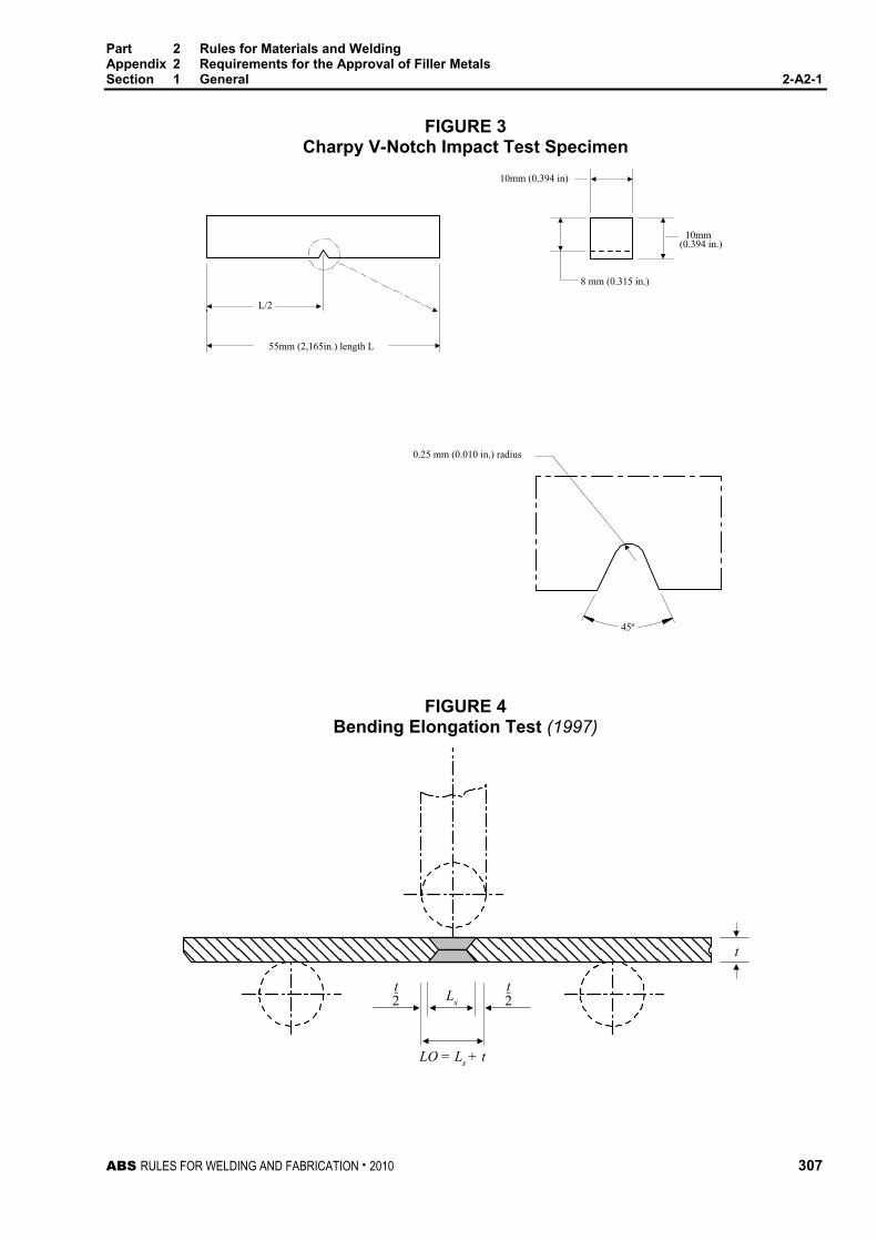
Part 2 Rules for Materials and Welding Appendix 2 Requirements for the Approval of Filler Metals Section 1 General 2-A2-1
ABS RULES FOR WELDING AND FABRICATION . 2010 307
FIGURE 3 Charpy V-Notch Impact Test Specimen
10mm(0.394 in.)
0.25 mm (0.010 in.) radius
8 mm (0.315 in.)
10mm (0.394 in)
L/2
55mm (2,165in.) length L
45º
FIGURE 4 Bending Elongation Test (1997)
t2
t2Ls
LO = Ls + t
t

Part 2 Rules for Materials and Welding Appendix 2 Requirements for the Approval of Filler Metals Section 1 General 2-A2-1
308 ABS RULES FOR WELDING AND FABRICATION . 2010
TABLE 1 Tension Test Requirements (2009)
The tensile requirements are based on the type of test specimen (longitudinal or transverse) specified elsewhere in these Requirements for the particular combination of weld process and the type of required test.
To find the required tension test properties, first locate in the “process” column the welding process for which the filler metal is intended (e.g., wire-flux). Then locate in that line under “applicable test” column the test in question (e.g., DM/M). The required properties are found below the box in which the particular test is located (longitudinal specimen for the example chosen).
Process Applicable Tests
MW DM BW WF DM/M, DM/TM, BW/T, BW/TM BW/M, BW/T, BW/TM
WG/SA DM BW WG/A DM/M, DM/TM, BW/T, BW/TM BW/M, BW/T, BW/TM ESEG BW BW
Required Properties Longitudinal Specimen Transv. Specimen (1999)
Grade (3) Tensile Strength N/mm2 (kgf/mm2, ksi)
Yield Point, min. N/mm2 (kgf/mm2, ksi)
Elongation min. %
Tensile Strength, min. N/mm2 (kgf/mm2, ksi)
1, 2 & 3 (2006) 400/560 (41/57, 58/82) 305 (31, 44) 22 400 (41, 58) 1Y (1), 2Y, 3Y & 4Y 490/660 (50/67, 71/95) 375 (38, 54) 22 490 (50, 71) 2Y400, 3Y400, 4Y400 & 5Y400
510/690 (52/70, 74/100) 400 (41, 58) 22 510 (52, 74)
XYQ420 (4) 530/680 54/69, 77/98) 420 (43,61) 20 530 (54, 77) XYQ460 (4) 570/720 (58/73, 83/104) 460 (47, 67) 20 570 (58, 83) XYQ500 (4) 610/770 (62/78, 88/112) 500 (51, 73) 18 610 (62, 88) XYQ550 (4) 670/830 (68/85, 97/120) 550 (56, 80) 18 670 (68, 97) XYQ620 (4) 720/890 (73/91, 104/129) 620 (63, 90) 18 720 (73, 104) XYQ690 (4) 770/940 (78/96, 112/136) 690 (70, 100) 17 770 (78, 112) Abbreviations: MW: Covered Electrode for Manual Welding A: Automatic WF: Wire-flux Combination M: Multi-run WG: Wire-gas Combination T: Two run*2 ESEG: Electroslag or Electrogas TM: Two run & Multi-run*2 SA: Semi-automatic DM: Deposited Metal Test BW: Butt Weld Test
Notes: 1 Grade 1Y not applicable to MW and WG/SA.
2 Two run not applicable to YQ Grades.
3 X = 3, 4 or 5. See 2-A2-1/Table 2. (1999)
4 (2006) Specifications for high strength quenched and tempered steels, for which these XYQ grades of welding consumables are intended, may be found in Appendix 3-1-A3, “Guide for Material Selection for ABS Grades of High Strength Quenched and Tempered Steel” of the ABS Rules for Building and Classing Mobile Offshore Drilling Units.
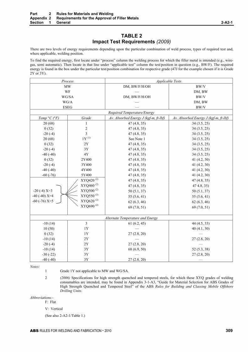
Part 2 Rules for Materials and Welding Appendix 2 Requirements for the Approval of Filler Metals Section 1 General 2-A2-1
ABS RULES FOR WELDING AND FABRICATION . 2010 309
TABLE 2 Impact Test Requirements (2009)
There are two levels of energy requirements depending upon the particular combination of weld process, types of required test and, where applicable, welding position.
To find the required energy, first locate under “process” column the welding process for which the filler metal is intended (e.g., wire-gas, semi automatic). Then locate in that line under “applicable test” column the test/position in question (e.g., BW/F). The required energy is found in the box under the particular test/position combination for respective grade (47J for the example chosen if it is Grade 2Y or 3Y).
Process Applicable Tests MW DM, BW/F/H/OH BW/V WF — DM, BW
WG/SA DM, BW/F/H/OH BW/V WG/A — DM, BW ESEG — BW/V
Required Temperature/Energy Temp °C (°F) Grade Av. Absorbed Energy J (kgf-m, ft-lbf) Av. Absorbed Energy J (kgf-m, ft-lbf)
20 (68) 1 47 (4.8, 35) 34 (3.5, 25) 0 (32) 2 47 (4.8, 35) 34 (3.5, 25)
-20 (-4) 3 47 (4.8, 35) 34 (3.5, 25) 20 (68) 1Y (1) See Note 1 34 (3.5, 25) 0 (32) 2Y 47 (4.8, 35) 34 (3.5, 25)
-20 (-4) 3Y 47 (4.8, 35) 34 (3.5, 25) -40 (-40) 4Y 47 (4.8, 35) 34 (3.5, 25)
0 (32) 2Y400 47 (4.8, 35) 41 (4.2, 30) -20 (-4) 3Y400 47 (4.8, 35) 41 (4.2, 30) -40 (-40) 4Y400 47 (4.8, 35) 41 (4.2, 30) -60 (-76) 5Y400 47 (4.8, 35) 41 (4.2, 30)
47 (4.8, 35) 47 (4.8, 35) 47 (4.8, 35) 47 4.8, 35) 50 (5.1, 37) 50 (5.1, 37) 55 (5.6, 41) 55 (5.6, 41) 62 (6.3, 46) 62 (6.3, 46) 69 (7.0, 51) 69 (7.0, 51)
-20 (-4) X=3 -40 (-40) X=4 -60 (-76) X=5
XYQ420 (2) XYQ460 (2) XYQ500 (2) XYQ550 (2) XYQ620 (2) XYQ690 (2)
Alternate Temperature and Energy
-10 (14) 3 61 (6.2, 45) 44 (4.5, 33) 10 (50) 1Y — 40 (4.1, 30) 0 (32) 1Y 27 (2.8, 20) —
-10 (14) 2Y — 27 (2.8, 20) -20 (-4) 2Y 27 (2.8, 20) — -10 (14) 3Y 68 (6.9, 50) 52 (5.3, 38) -30 (-22) 3Y — 27 (2.8, 20) -40 (-40) 3Y 27 (2.8, 20) —
Notes: 1 Grade 1Y not applicable to MW and WG/SA.
2 (2006) Specifications for high strength quenched and tempered steels, for which these XYQ grades of welding consumables are intended, may be found in Appendix 3-1-A3, “Guide for Material Selection for ABS Grades of High Strength Quenched and Tempered Steel” of the ABS Rules for Building and Classing Mobile Offshore Drilling Units.
Abbreviations:- F: Flat
V: Vertical
(See also 2-A2-1/Table 1.)

310 ABS RULES FOR WELDING AND FABRICATION . 2010
P A R T S e c t i o n 2 : E l e c t r o d e s f o r S h i e l d e d M e t a l A r c W e l d i n g
2 A P P E N D I X 2 Requirements for the Approval of Filler Metals
S E C T I O N 2 Electrodes for Shielded Metal Arc Welding
1 General The annual check test shall consist of two deposited metal test assemblies welded and tested in accordance with 2-A2-2/5.
3 Chemical Analysis The chemical analysis of the deposited weld metal is to be supplied by the manufacturer.
5 Deposited Metal Test Assemblies
5.1 Test Assembly (2005) Two deposited metal test assemblies, as indicated in 2-A2-2/Figure 1, are to be welded in the flat position, one using 4 mm (5/32 in.) electrodes or the smallest size manufactured, whichever is greater, and the other using the largest size manufactured. If an electrode is produced in one size only or if the largest size produced is 4 mm (5/32 in.) or less, one test assembly is sufficient. The weld metal is to be deposited in single or multi-run layers according to normal practice, and the direction of deposition of each layer is to alternate from each end of the plate, each run of weld metal being not less than 2 mm (5/64 in.) and not more than 4 mm (5/32 in.) thick. Between each run, the assembly is to be left in still air until it has cooled to less than 250°C (482°F), but not below 100°C (212°F), the temperature being taken in the center of the weld, on the surface of the seam. After being welded, the test assemblies are not to be subjected to any heat treatment, except hydrogen removal, as permitted in 2-A2-1/15.3.
5.3 Test Specimens (1 October 1994) One tension and one set of three impact specimens are to be prepared from each deposited metal test assembly, as indicated in 2-A2-2/Figure 1, and the results are to conform to the requirements of 2-A2-1/Table 1 and 2-A2-1/Table 2 for the applicable grade and welding technique.
7 Butt Weld Test Assemblies
7.1 Test Assemblies One butt weld test assembly, as indicated in 2-A2-2/Figure 2, is to be welded in each position (flat, vertical-up, vertical-down, overhead and horizontal) for which the electrode is recommended by the manufacturer, except that those electrodes meeting the requirements for flat and vertical positions will be considered as also complying with the requirements for the horizontal position. Where the electrode is only to be approved in the flat position, one additional test assembly is to be welded in that position.

Part 2 Rules for Materials and Welding Appendix 2 Requirements for the Approval of Filler Metals Section 2 Electrodes for Shielded Metal Arc Welding 2-A2-2
ABS RULES FOR WELDING AND FABRICATION . 2010 311
7.3 Welding Procedure (1996) In general, the following welding procedure is to be adopted in making the test assemblies:
Flat. First run using 4 mm (5/32 in.) electrodes; remaining runs except last two layers with 5 mm (3/16 in.) or above according to the normal welding practice with the electrodes; the runs of the last two layers with the largest size electrodes manufactured. When a second flat assembly is required, the runs of the last three layers are to be welded with the largest size electrode manufactured.
Horizontal. First pass with 4 mm (5/32 in.) or 5 mm (3/16 in.) diameter electrode. Subsequent passes with 5 mm (3/16 in.) diameter electrode.
Vertical-up and Overhead. The first run with 3.25 mm (1/8 in.) electrodes; remaining runs with the largest diameter recommended by the manufacturer for the position concerned.
Vertical down. The electrode diameter used is to be as recommended by the manufacturer.
For all assemblies, the back weld is to be made with 4 mm (5/32 in.) electrodes in the welding position appropriate to each test sample, after removing the root run to clean metal. For electrodes suitable only for flat position welding, the test assemblies may be turned over to carry out the back weld.
Normal welding practice is to be used, and between each run, the assembly is to be left in still air until it has cooled to less than 250°C (482°F) but not below 100°C (212°F), the temperature being taken in the center of the weld, on the surface of the seam. After welding, the test assemblies are not to be subjected to any heat treatment.
7.5 Test Specimens (2008) One tension, one face bend, one root bend are to be prepared from each butt weld test assembly together with one set of three impact specimens from the flat and vertical test assemblies, as indicated in 2-A2-2/Figure 2. The results of tension and impact tests are to conform to the requirements of 2-A2-1/Table 1 and 2-A2-1/Table 2 for the applicable grade, position and welding technique. The results of bend tests are to meet the requirements of 2-A2-1/21.3.
9 Fillet Weld Test Assemblies
9.1 General (2005) For gravity fillet welding electrodes (including combination gravity/manual electrodes), fillet weld testing is required in addition to deposited metal testing. Butt weld testing is not required. For gravity welding electrodes (including combination gravity/manual electrodes) intended for both fillet and butt welding, fillet weld testing is required in addition to deposited metal and butt weld testing. Gravity welding equipment is to be used in welding fillet weld test assemblies. Such fillet weld tests are to be carried out and tested in accordance with 2-A2-2/9.3 through 2-A2-2/9.7 using gravity welding equipment and the longest size electrode manufactured.
The following applies to SMAW electrodes other than gravity electrodes: An electrode other than YQ Grades is considered approved for fillet welding in position for which the butt weld test of 2-A2-2/7 was satisfactory. Electrodes meeting the flat butt weld requirements will be considered as complying with the requirements for horizontal fillet (HF) welds. Where an electrode is submitted for approval for fillet welds only, the butt weld tests indicated in 2-A2-2/7 may be omitted and fillet weld tests are to be carried out and tested in accordance with 2-A2-2/9.3 through 2-A2-2/9.7.
9.3 Test Assemblies One fillet weld test assembly, as indicated in 2-A2-2/Figure 3, is to be welded in each position for which the electrode is recommended by the manufacturer.

Part 2 Rules for Materials and Welding Appendix 2 Requirements for the Approval of Filler Metals Section 2 Electrodes for Shielded Metal Arc Welding 2-A2-2
312 ABS RULES FOR WELDING AND FABRICATION . 2010
9.5 Welding Procedure The length L of the fillet test assemblies is to be sufficient to allow for the tests required in 2-A2-2/9.7 and is to provide for at least the deposition of the entire length of the electrode being tested. One side is to be welded using the maximum size electrode manufactured and the second side using the minimum size of electrode manufactured that is recommended for fillet welds. The fillet size will, in general, be determined by the electrode size and the welding current employed during testing. The fillet weld is to be carried out with the longest size electrode using the welding equipment and technique recommended by the manufacturer. The current used while conducting the test, and the manufacturer’s recommended current range are to be reported for each electrode size and welding position.
9.7 Test Specimens 9.7.1 Macrographs and Hardness Tests (1 October 1994)
Each fillet weld test assembly is to be sectioned, as indicated in 2-A2-2/Figure 3, to form three macro-sections. These are to be examined for root penetration, satisfactory profile, freedom from cracking and reasonable freedom from porosity, undercut and slag inclusions. Hardness readings are to be made on each section. The number and location of hardness readings are to approximate those indicated in 2-A2-2/Figure 4. The hardness of the weld is to be determined and is to meet the following listed equivalent values.
Load Grade 1, 2, 3 Grades Y, Y400 and YQ Diamond Pyramid (Vickers)
Hardness-10 kg (98 N) To be reported for information 150 min.
Rockwell B-100 kg (980 N) 80 min.
The hardness of the heat affected zone (HAZ) and base metal are also to be determined and reported for information only.
9.7.2 Breaking Test One of the remaining sections of the fillet weld is to have the weld, on the side welded first, gouged or machined to facilitate breaking the fillet weld on the other side by closing the two plates together, subjecting the root of the weld to tension. On the other remaining section, the weld on the side welded second is to be gouged or machined and the section fractured using the above procedure. The fractured surfaces are to be examined and there is to be no evidence of incomplete penetration or internal cracking and they are to be reasonably free from porosity.
11 Low Hydrogen Approval (1997)
11.1 Ordinary-Strength Filler Metals (1997) Electrodes which have satisfied the requirements of Grades 2 and 3 may, at the option of the manufacturer, be subjected to a hydrogen test, as specified in 2-A2-1/23.3. A suffix indicating the hydrogen amount will be added to the grade number of those electrodes to indicate compliance with the hydrogen test requirements specified in 2-A2-1/23.7.
11.3 Higher-Strength Filler Metals (2009) Electrodes which are submitted for approval according to Grades 2Y, 3Y, 4Y, 2Y400, 3Y400, 4Y400, or 5Y400 are to be subjected to a hydrogen test and are to meet the requirement specified in 2-A2-1/23.7 for the H10 suffix. Such suffix, however, will not be added to the grade. Electrodes meeting H5 requirements will be so identified. Electrodes meeting the higher-strength requirements, except for hydrogen test, will require special approval for use on higher strength steel for each user and will be so identified in the list of approved electrodes.
11.5 YQ Grade Filler Metals (2005) Electrodes which are submitted for approval according to YQ Grades are to be subjected to a hydrogen test, as specified in 2-A2-1/23.1. The YQ420/460/500 grades meeting the H5 requirements will be so identified. Otherwise, the H-suffix will not be added to the grade.

Part 2 Rules for Materials and Welding Appendix 2 Requirements for the Approval of Filler Metals Section 2 Electrodes for Shielded Metal Arc Welding 2-A2-2
ABS RULES FOR WELDING AND FABRICATION . 2010 313
13 Annual Check Tests
13.1 General (1 October 1993) The annual check test shall consist of two deposited metal test assemblies welded and tested in accordance with 2-A2-2/5.
13.3 Upgrading and Uprating (2008) Upgrading of electrodes will be considered at the manufacturer’s request. In addition to the two deposited metal tests indicated in 2-A2-2/13.1, a butt weld test assembly is to be welded as indicated in 2-A2-2/7 for each position initially tested, and sets of three impact specimens from each test assembly are to be tested at the upgraded temperature.
Uprating refers to the extension of approval to also cover the welding of higher-strength steels (dual approvals). For this purpose, butt weld tests are to be carried out, as required in 2-A2-1/9.3.3 and 2-A2-2/7. In addition, the diffusible hydrogen test required by the grade or suffix referred to in 2-A2-2/11.1 and 2-A2-2/11.3 is to be conducted.

Part 2 Rules for Materials and Welding Appendix 2 Requirements for the Approval of Filler Metals Section 2 Electrodes for Shielded Metal Arc Welding 2-A2-2
314 ABS RULES FOR WELDING AND FABRICATION . 2010
FIGURE 1 Deposited-Metal Test Assembly for Manual and Gas-Metal Arc Welding
Tack weld both sides
(0.64 in.)
(1.2 in.)
(0.75 in.)
Impact test specimens
Tensile test specimen
20 mm (0.75 in.) min.Line of cut for tensiletest specimen
20 mm
10 mm (0.40 in.)
16 mm
10° 10°
100 mm (4.0 in.) min. 100 mm (4.0 in.) min.
30 mm

Part 2 Rules for Materials and Welding Appendix 2 Requirements for the Approval of Filler Metals Section 2 Electrodes for Shielded Metal Arc Welding 2-A2-2
ABS RULES FOR WELDING AND FABRICATION . 2010 315
FIGURE 2 Butt-Weld Test Assembly for Manual and Gas-Metal Arc Welding
Impact test specimens
Tensile testspecimen
Bend testspecimen
Bend testspecimen
50mm(2.0 in.)
30mm(1.2 in.)
30mm(1.2 in.)
15-20mm(0.62-0.75 in.)
(0.08-0.125 in.)
100mm (4.0 in.) min.
2-3 mm
100mm (4.0 in.) min.
60°
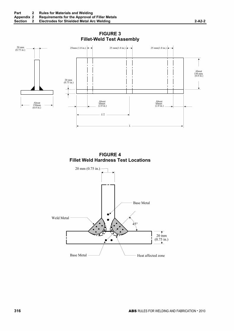
Part 2 Rules for Materials and Welding Appendix 2 Requirements for the Approval of Filler Metals Section 2 Electrodes for Shielded Metal Arc Welding 2-A2-2
316 ABS RULES FOR WELDING AND FABRICATION . 2010
FIGURE 3 Fillet-Weld Test Assembly
About
About150mm(6.0 in.)
About50mm(2.0 in.)
20 mm(0.75 in.)
(0.75 in.)
(6.0 in.)
25 mm(1.0 in.)25 mm(1.0 in.)20 mm 25mm (1.0 in.)
L
L/2
150 mm
About50mm(2.0 in.)
FIGURE 4 Fillet Weld Hardness Test Locations
Base Metal
45°
Heat affected zone
Weld Metal
Base Metal
20 mm(0.75 in.)
20 mm (0.75 in.)

ABS RULES FOR WELDING AND FABRICATION . 2010 317
P A R T S e c t i o n 3 : W i r e - F l u x C o m b i n a t i o n s f o r S u b m e r g e d A r c W e l d i n g
2 A P P E N D I X 2 Requirements for the Approval of Filler Metals
S E C T I O N 3 Wire-Flux Combinations for Submerged Arc Welding
1 General (1997) This test program is intended for the approval of automatic or semi-automatic, single-electrode submerged arc welding. Provisions are made for the testing of weld metal deposited by multi-run and two-run (one pass each side) techniques. For YQ Grades automatic welding, a multi-run technique is contemplated. Application for high heat input process, such as automatic welding two-run technique, may be considered under 2-A2-1/3.5 and approval by a technical office. Where a manufacturer states that a particular wire-flux combination is suitable for welding with both techniques, both series of tests are to be carried out. The suffix T, M, or TM will be added to the grade to indicate two-run technique, multi-run technique, or both techniques, respectively.
3 Chemical Analysis The chemical analysis of the deposited weld metal is to be supplied by the manufacturer.
5 Deposited Metal Test Assemblies for Multi-run Technique
5.1 Test Assembly (2005) One deposited metal test assembly, as indicated in 2-A2-3/Figure 1, is to be welded in the flat position using the wire size recommended by the manufacturer. The direction of deposition of each run is to alternate from each end of the plate and after completion of each run, the flux and welding slag are to be removed. The thickness of each layer is not to be less than the size of the wire, or 4 mm (5/32 in.), whichever is the greater. Between each run, the assembly is to be left in still air until it has cooled to less than 250°C (482°F), but not below 100°C (212°F), the temperature being taken in the center of the weld, on the surface of the seam. The welding conditions (amperage, voltage, and travel speed) are to be in accordance with the recommendations of the manufacturer and are to conform with normal good welding practice for multi-run welding. The welded test assembly is not to be subjected to heat treatment, except hydrogen removal, as permitted in 2-A2-1/15.3.
5.3 Test Specimens (1 October 1994) Two tension and one set of three impact specimens are to be prepared from the deposited metal test assembly, as indicated in 2-A2-3/Figure 1, and the results are to conform to the requirements of 2-A2-1/Table 1 and 2-A2-1/Table 2 for the applicable grade and welding technique.
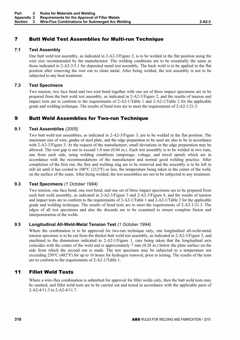
Part 2 Rules for Materials and Welding Appendix 2 Requirements for the Approval of Filler Metals Section 3 Wire-Flux Combinations for Submerged Arc Welding 2-A2-3
318 ABS RULES FOR WELDING AND FABRICATION . 2010
7 Butt Weld Test Assemblies for Multi-run Technique
7.1 Test Assembly One butt weld test assembly, as indicated in 2-A2-3/Figure 2, is to be welded in the flat position using the wire size recommended by the manufacturer. The welding conditions are to be essentially the same as those indicated in 2-A2-3/5.1 for deposited metal test assembly. The back weld is to be applied in the flat position after removing the root run to clean metal. After being welded, the test assembly is not to be subjected to any heat treatment.
7.3 Test Specimens Two tension, two face bend and two root bend together with one set of three impact specimens are to be prepared from the butt weld test assembly, as indicated in 2-A2-3/Figure 2, and the results of tension and impact tests are to conform to the requirements of 2-A2-1/Table 1 and 2-A2-1/Table 2 for the applicable grade and welding technique. The results of bend tests are to meet the requirements of 2-A2-1/21.3.
9 Butt Weld Assemblies for Two-run Technique
9.1 Test Assemblies (2005) Two butt weld test assemblies, as indicated in 2-A2-3/Figure 3, are to be welded in the flat position. The maximum size of wire, grades of steel plate, and the edge preparation to be used are also to be in accordance with 2-A2-3/Figure 3. At the request of the manufacturer, small deviations in the edge preparation may be allowed. The root gap is not to exceed 1.0 mm (0.04 in.). Each test assembly is to be welded in two runs, one from each side, using welding conditions (amperage, voltage, and travel speed) which are in accordance with the recommendations of the manufacturer and normal good welding practice. After completion of the first run, the flux and welding slag are to be removed and the assembly is to be left in still air until it has cooled to 100°C (212°F) or less, the temperature being taken in the center of the weld, on the surface of the seam. After being welded, the test assemblies are not to be subjected to any treatment.
9.3 Test Specimens (1 October 1994) Two tension, one face bend, one root bend, and one set of three impact specimens are to be prepared from each butt weld assembly, as indicated in 2-A2-3/Figure 3 and 2-A2-3/Figure 4, and the results of tension and impact tests are to conform to the requirements of 2-A2-1/Table 1 and 2-A2-1/Table 2 for the applicable grade and welding technique. The results of bend tests are to meet the requirements of 2-A2-1/21.3. The edges of all test specimens and also the discards are to be examined to ensure complete fusion and interpenetration of the welds.
9.5 Longitudinal All-Weld-Metal Tension Test (1 October 1994) Where the combination is to be approved for two-run technique only, one longitudinal all-weld-metal tension specimen is to be cut from the thicker butt weld test assembly, as indicated in 2-A2-3/Figure 3, and machined to the dimensions indicated in 2-A2-1/Figure 1, care being taken that the longitudinal axis coincides with the center of the weld and is approximately 7 mm (0.28 in.) below the plate surface on the side from which the second run is made. The test specimen may be subjected to a temperature not exceeding 250°C (482°F) for up to 16 hours for hydrogen removal, prior to testing. The results of the tests are to conform to the requirements of 2-A2-1/Table 1.
11 Fillet Weld Tests Where a wire-flux combination is submitted for approval for fillet welds only, then the butt weld tests may be omitted, and fillet weld tests are to be carried out and tested in accordance with the applicable parts of 2-A2-4/11.3 to 2-A2-4/11.7.

Part 2 Rules for Materials and Welding Appendix 2 Requirements for the Approval of Filler Metals Section 3 Wire-Flux Combinations for Submerged Arc Welding 2-A2-3
ABS RULES FOR WELDING AND FABRICATION . 2010 319
13 Low Hydrogen Approval (1997)
13.1 YQ Grade Wires – Flux Combination (2005) All wire-flux combination of this grade are to be submitted to the diffusible hydrogen test, as required by 2-A2-1/23.1. The YQ420/460/500 grades meeting the H5 requirements will be so identified. Otherwise, the H-suffix will not be added to the grade.
15 Annual Check Tests
15.1 General (1996) The annual check tests for each approved technique shall consist of the following.
Multi-run Technique. One deposited metal test assembly is to be welded in accordance with 2-A2-3/5.1. One tension and one set of three impact specimens are to be prepared and tested in accordance with 2-A2-3/5.3.
Two-run Technique. One butt weld test assembly of 20 mm (0.75 in.) thickness is to be welded in accordance with 2-A2-3/9.1. One transverse tension, one face bend, one root bend, and one set of three impact specimens are to be prepared and tested in accordance with 2-A2-3/9.3 and 2-A2-3/9.5. One longitudinal tension test specimen is also to be prepared where wire-flux combination is approved solely for the two-run technique.
15.3 Upgrading and Uprating (2008) Upgrading of wire-flux combinations will be considered at the manufacturer’s request. For multi-run technique, in addition to the deposited metal test indicated in 2-A2-3/15.1, one butt weld test assembly is to be welded, as indicated in 2-A2-3/7, and one set of three impact specimens is to be tested at the upgraded temperature. For the two-run technique, butt weld testing is to be carried out as indicated in 2-A2-3/15.1, except the test assembly is to be fabricated using the maximum thickness approved.
Uprating refers to the extension of approval to also cover welding of higher-strength steels (dual approvals). For this purpose butt weld tests are to be carried out as required in 2-A2-3/7 and 2-A2-3/9, and 2-A2-1/9.3.3, as applicable.
17 Multiple Electrodes Wire-flux combinations for multiple electrode submerged arc welding will be subject to separate approval tests. They are to be carried out generally in accordance with the requirements of this section.
19 Electroslag Welding (1996)
19.1 General (1997) Where approval is requested for wire-flux combinations other than YQ Grades, (with or without consumable nozzles) for use in electroslag welding, two test assemblies of 20–25 mm (0.75–1.0 in.) and 35–40 mm (1.38–1.58 in.) or more in thickness are to be prepared with a minimum root opening of 16 mm (0.63 in.), or with another joint design sufficient to allow the selection of the following test specimens. The chemical composition of the plates including the content of grain refining elements is to be reported.
• 2 longitudinal tension specimens from the axis to the weld,
• 2 transverse tension specimens,
• 2 side bend specimens,
• 3 Charpy-V specimens notched at the center of the weld,
• 3 Charpy-V specimens with their notches in the weld metal at 2 mm (5/64 in.) from the fusion line,
• 2 macro-sections.
The results are to conform to the requirements of 2-A2-1/Table 1 and 2-A2-1/Table 2, according to the applicable grade and welding technique.

Part 2 Rules for Materials and Welding Appendix 2 Requirements for the Approval of Filler Metals Section 3 Wire-Flux Combinations for Submerged Arc Welding 2-A2-3
320 ABS RULES FOR WELDING AND FABRICATION . 2010
19.3 Annual Tests (1996) One butt test assembly of 20–25 mm (0.75–1.0 in.) or more in thickness is to be prepared. One longitudinal tension, one transverse tension, two side bend and two sets of three Charpy V-notch specimens are to be prepared and tested. The notch of the impact specimens is to be located at the center of the weld and 2 mm (0.08 in.) from the fusion line in the weld. One macro-section is also to be examined.
The test results are to conform to the requirements of 2-A2-1/Table 1 and 2-A2-1/Table 2, according to the applicable grade and welding technique.
19.5 Upgrading and Uprating (1996) Upgrading and uprating will be considered at the manufacturer’s request. Full tests as indicated in 2-A2-3/19.1 will be required.
The test results are to conform to the requirements of 2-A2-1/Table 1 and 2-A2-1/Table 2, according to the applicable grade and welding technique.

Part 2 Rules for Materials and Welding Appendix 2 Requirements for the Approval of Filler Metals Section 3 Wire-Flux Combinations for Submerged Arc Welding 2-A2-3
ABS RULES FOR WELDING AND FABRICATION . 2010 321
FIGURE 1 Deposited-Metal Test Assembly for Submerged Arc Welding – Multi-run Technique
and Automatic Gas-Metal Arc Welding
Tensile testspecimen
Impact test
Tensile test
specimens
specimen
30 mm (1.2 in.) min.Line of cut fortensile test specimen
Tack weld both sides
(0.75 in.)20 mm
12 mm (0.5 in.)
16 mm(0.64 in.)
(20 in.)
10° 10°
50 mm
200 mm (8.0 in.) min. 200 mm (8.0 in.) min.
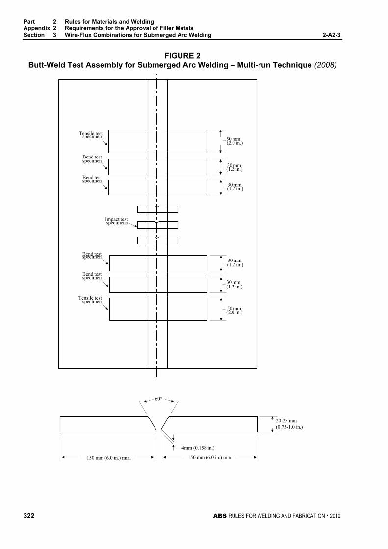
Part 2 Rules for Materials and Welding Appendix 2 Requirements for the Approval of Filler Metals Section 3 Wire-Flux Combinations for Submerged Arc Welding 2-A2-3
322 ABS RULES FOR WELDING AND FABRICATION . 2010
FIGURE 2 Butt-Weld Test Assembly for Submerged Arc Welding – Multi-run Technique (2008)
Tensile testspecimen
Bend testspecimen
specimenBend test
Impact testspecimens
specimenBend test
Bend testspecimen
Tensile testspecimen
50 mm(2.0 in.)
30 mm(1.2 in.)
30 mm(1.2 in.)
30 mm(1.2 in.)
30 mm(1.2 in.)
50 mm(2.0 in.)
4mm (0.158 in.)
60°
150 mm (6.0 in.) min.150 mm (6.0 in.) min.
20-25 mm(0.75-1.0 in.)

Part 2 Rules for Materials and Welding Appendix 2 Requirements for the Approval of Filler Metals Section 3 Wire-Flux Combinations for Submerged Arc Welding 2-A2-3
ABS RULES FOR WELDING AND FABRICATION . 2010 323
FIGURE 3 Butt-Weld Test Assembly for Submerged Arc Welding – Two-run Technique (2009)
Tensile testspecimen
Bend test
Impact test
Bend testspecimen
Tensile textspecimen
Longitudinal tensiletest specimen (when
approval requiredfor two run technique
only)
Line of cut forlongitudinal tensiletest specimen
30 mm (1.2 in.) minimum
30 mm (1.2in.)for plates up to
20 mm (0.75in) thickor 1 1/2 times thickness
for plates greater than20 mm (0.75 in)
(2.0 in..)
(2.0 in..)
50mm
specimen
specimen
50 mm
150mm(6.0in.)min 150mm(6.0in.)min
Grades of Steel Wire Flux
Grade Ordinary Strength
Higher Strength
1, 1Y A AH32/36
1, 1Y A AH332/36 2, 2Y A/B/D AH/DH32/36 2Y400 - AH/DH40 3, 3Y A/B/D/E AH/DH/EH32/36 3Y400 - AH/DH/EH40
4Y - AH/DH/EH/FH32/36 4Y400, 5Y400 - AH/DH/EH/FH40
2, 2Y A/B/D AH/DH32/36 2Y400 - AH/DH40 3, 3Y A/B/D/E AH/DH/EH32/36 3Y400 - AH/EH/EH40
PlateThickness
12-15 mm
PreparationMaximum sizesof Wire
(0.5-0.62 in.)
20-25mm(0.75-1.0 in.)
30-35 mm(1.2-1.38 in.)
7 mm(0.28 in.)
6 mm(0.25 in.)
5 mm(0.20 in.)
8-12mm (0.32-0.50in.)
6-14mm (0.24-0.55in.)
60°
70°
4Y - AH/DH/EH/FH32/36
4Y400, 5Y 400 - AH/DH/EH/FH40

Part 2 Rules for Materials and Welding Appendix 2 Requirements for the Approval of Filler Metals Section 3 Wire-Flux Combinations for Submerged Arc Welding 2-A2-3
324 ABS RULES FOR WELDING AND FABRICATION . 2010
FIGURE 4 Butt-Weld Impact Specimen Location for Submerged and Gas-Metal Arc Welding –
Two-run Technique Notch perpendicular tosurface of plate
2nd run
2nd run
2nd run
(0.5-0.62 in.)
(0.75-1.0 in.)
(0.08 in.)
(0.08 in.)
12-15 mm
2 mm
2 mm
(1.2-1.38 in.)
20-25 mm
30-35 mm

ABS RULES FOR WELDING AND FABRICATION . 2010 325
P A R T Section 4: Wire and Wire Gas Combinations for Gas Metal Arc Welding and Flux Cored Wires for Flux Cored Arc Welding
2 A P P E N D I X 2 Requirements for the Approval of Filler Metals
S E C T I O N 4 Wire and Wire Gas Combinations for Gas Metal Arc Welding and Flux Cored Wires for Flux Cored Arc Welding
1 General (1997) This test program is intended for the approval of wire-gas combinations and flux cored wires with or without shielding gas intended for semi-automatic or automatic arc welding techniques. For both techniques, the welding gun provides continuous wire feed; for semi-automatic welding, the welding gun is held manually, and for automatic welding, the welding gun is machine held with various degrees of controlled motion provided by the machine. The impact requirements for the semi-automatic welding technique and those for the automatic welding technique are indicated separately in 2-A2-1/Table 1 and 2-A2-1/Table 2, according to the applicable grade. The suffix SA will be added to the grade to indicate approval for manual semi-automatic or machine-automatic gas-metal arc welding. The suffix A will be added to the Grade to indicate approval for machine automatic welding only. An additional suffix T will be added to the grade to indicate approval for two-run (one pass each side) technique for machine automatic welding. Wire-gas combinations and flux cored wires approved for semi-automatic welding may be used for automatic welding under the procedure recommended by the manufacturer, except that for the two-run automatic technique, testing in accordance with 2-A2-4/9 is required. For YQ Grades semi-automatic or automatic welding, a multi run technique is contemplated. Application for high heat input process, such as semi-automatic or automatic welding two-run technique, may be considered under 2-A2-1/3.5 and approval by the technical office.
3 Chemical Analysis and Shielding Gas Compositions (2008) The chemical analysis of the deposited weld metal is to be supplied by the manufacturer. The trade name of the shielding gas, when used, as well as its composition, is to be reported. The approval of a wire in combination with any particular gas can be applied or transferred to any combination of the same wire and any gas in the same numbered group as defined in 2-A2-4/Table 1.
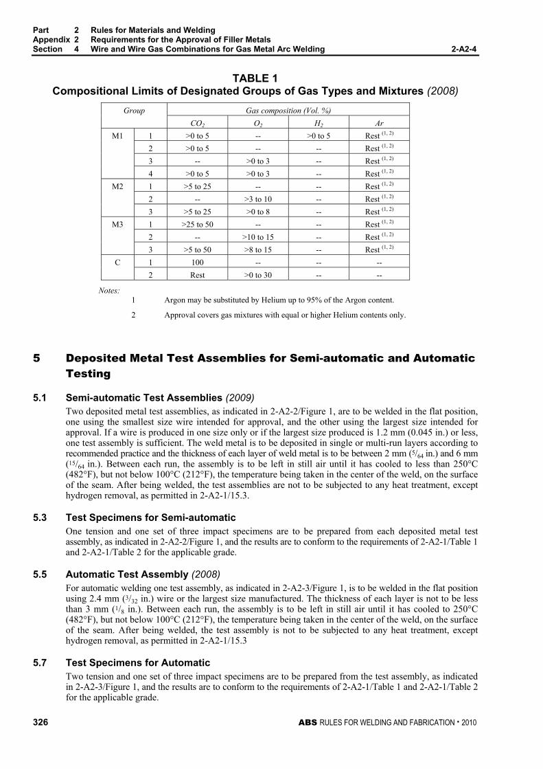
Part 2 Rules for Materials and Welding Appendix 2 Requirements for the Approval of Filler Metals Section 4 Wire and Wire Gas Combinations for Gas Metal Arc Welding 2-A2-4
326 ABS RULES FOR WELDING AND FABRICATION . 2010
TABLE 1 Compositional Limits of Designated Groups of Gas Types and Mixtures (2008)
Gas composition (Vol. %) Group CO2 O2 H2 Ar
1 >0 to 5 -- >0 to 5 Rest (1, 2)
2 >0 to 5 -- -- Rest (1, 2)
3 -- >0 to 3 -- Rest (1, 2)
M1
4 >0 to 5 >0 to 3 -- Rest (1, 2) 1 >5 to 25 -- -- Rest (1, 2)
2 -- >3 to 10 -- Rest (1, 2)
M2
3 >5 to 25 >0 to 8 -- Rest (1, 2) 1 >25 to 50 -- -- Rest (1, 2) 2 -- >10 to 15 -- Rest (1, 2)
M3
3 >5 to 50 >8 to 15 -- Rest (1, 2) 1 100 -- -- -- C 2 Rest >0 to 30 -- --
Notes: 1 Argon may be substituted by Helium up to 95% of the Argon content.
2 Approval covers gas mixtures with equal or higher Helium contents only.
5 Deposited Metal Test Assemblies for Semi-automatic and Automatic Testing
5.1 Semi-automatic Test Assemblies (2009) Two deposited metal test assemblies, as indicated in 2-A2-2/Figure 1, are to be welded in the flat position, one using the smallest size wire intended for approval, and the other using the largest size intended for approval. If a wire is produced in one size only or if the largest size produced is 1.2 mm (0.045 in.) or less, one test assembly is sufficient. The weld metal is to be deposited in single or multi-run layers according to recommended practice and the thickness of each layer of weld metal is to be between 2 mm (5/64 in.) and 6 mm (15/64 in.). Between each run, the assembly is to be left in still air until it has cooled to less than 250°C (482°F), but not below 100°C (212°F), the temperature being taken in the center of the weld, on the surface of the seam. After being welded, the test assemblies are not to be subjected to any heat treatment, except hydrogen removal, as permitted in 2-A2-1/15.3.
5.3 Test Specimens for Semi-automatic One tension and one set of three impact specimens are to be prepared from each deposited metal test assembly, as indicated in 2-A2-2/Figure 1, and the results are to conform to the requirements of 2-A2-1/Table 1 and 2-A2-1/Table 2 for the applicable grade.
5.5 Automatic Test Assembly (2008) For automatic welding one test assembly, as indicated in 2-A2-3/Figure 1, is to be welded in the flat position using 2.4 mm (3/32 in.) wire or the largest size manufactured. The thickness of each layer is not to be less than 3 mm (1/8 in.). Between each run, the assembly is to be left in still air until it has cooled to 250°C (482°F), but not below 100°C (212°F), the temperature being taken in the center of the weld, on the surface of the seam. After being welded, the test assembly is not to be subjected to any heat treatment, except hydrogen removal, as permitted in 2-A2-1/15.3
5.7 Test Specimens for Automatic Two tension and one set of three impact specimens are to be prepared from the test assembly, as indicated in 2-A2-3/Figure 1, and the results are to conform to the requirements of 2-A2-1/Table 1 and 2-A2-1/Table 2 for the applicable grade.

Part 2 Rules for Materials and Welding Appendix 2 Requirements for the Approval of Filler Metals Section 4 Wire and Wire Gas Combinations for Gas Metal Arc Welding 2-A2-4
ABS RULES FOR WELDING AND FABRICATION . 2010 327
7 Butt Weld Test Assemblies for Semi-automatic and Automatic Techniques
7.1 Test Assemblies One butt weld test assembly, as indicated in 2-A2-2/Figure 2, is to be welded in each position (flat, vertical-up, vertical-down, overhead, and horizontal) for which the wire is recommended by the manufacturer, except that wires meeting the requirements for flat and vertical positions will be considered as also complying with the requirements for horizontal position. Where the wire is only to be approved in the flat position, one additional test assembly is to be welded in that position.
7.3 Welding Procedure (2009) In general, the following welding procedure is to be adopted in making the test assemblies:
Flat. First run using the smallest size wire intended for; remaining runs with the largest size intended for approval. Where a second flat assembly is required, it is to be prepared using wires of different sizes.
Vertical-up, Vertical-down, Overhead and Horizontal. First run with the smallest size wire intended for approval; remaining runs using the largest size wire intended for approval recommended by the manufacturer for the position involved.
In all cases, the back weld is to be made with the smallest size wire intended for approval, after removing the root run to clean metal. Normal welding practice is to be used and between each run, the assembly is to be left in still air until it has cooled to less than 250°C (482°F), but not below 100°C (212°F), the temperature being taken in the center of the weld on the surface of the seam. After being welded, the test assemblies are not to be subjected to any heat treatment.
7.5 Test Specimens (2005) One tension, one face bend, one root bend, and one set of three impact specimens are to be prepared from each butt-weld test assembly, as indicated in 2-A2-2/Figure 2. The results of tension and impact tests are to conform to the requirements of 2-A2-1/Table 1 and 2-A2-1/Table 2 for the applicable grade, position and welding technique. The results of bend tests are to meet the requirements of 2-A2-1/21.3.
9 Butt Weld Test Assemblies for Two-run Technique
9.1 Test Assemblies Two butt weld test assemblies, as indicated in 2-A2-4/Figure 1, are to be welded in the flat position. One test assembly is to be welded using 1.2 mm (0.045 in.) wire or the smallest size manufactured, whichever is greater and one test assembly using 2.4 mm (3/32 in.) wire or the largest size wire recommended by the manufacturer for two-run technique. Each test assembly is to be welded in two runs, one from each side. Between each run, the assembly is to be left in still air until it has cooled to 100°C (212°F), the temperature being taken in the center of the weld, on the surface of the seam. After being welded, the test assemblies are not to be subjected to any heat treatment.
9.3 Test Specimens (1996) Two tension, one face bend, one root bend and one set of three impact specimens are to be prepared from each butt weld test assembly, as indicated in 2-A2-4/Figure 1 and 2-A2-3/Figure 4. If approval is requested for welding plate thicker than 25 mm (1.0 in.), one assembly is to be prepared using plates approximately 20 mm (0.75 in.) in thickness and the other using plates of the maximum thickness for which approval is requested. For assemblies using plates over 25 mm (1.0 in.) in thickness, the edge preparation is to be reported for information. The results of tension and impact tests are to conform to the requirements of 2-A2-1/Table 1 and 2-A2-1/Table 2 for the applicable grade. The results of bend tests are to meet the requirements of 2-A2-1/21.3. The edges of all test specimens and also the discards are to be examined to ensure complete fusion and interpenetration of the welds.
Part 2 Rules for Materials and Welding Appendix 2 Requirements for the Approval of Filler Metals Section 4 Wire and Wire Gas Combinations for Gas Metal Arc Welding 2-A2-4
328 ABS RULES FOR WELDING AND FABRICATION . 2010
9.5 Longitudinal All-Weld-Metal Tension Test Where the wire is to be approved for two-run technique only, one longitudinal all-weld-metal tension specimen is to be cut from the thicker butt weld test assembly, as indicated in 2-A2-4/Figure 1, and machined to the dimensions indicated in 2-A2-1/Figure 1, care being taken that the longitudinal axis coincides with the center of the weld and is about 7 mm (0.28 in.) below the plate surface on the side from which the second run is made. The test specimen may be subjected to a temperature not exceeding 250°C (482°F) for a period not exceeding 16 hours for hydrogen removal, prior to testing. The results of the test are to conform to the requirements of 2-A2-1/Table 1 and 2-A2-1/Table 2 for the applicable grade.
11 Fillet Weld Tests
11.1 General A wire-gas combination or flux cored wire is considered approved for fillet welding in the welding position for which the butt weld test of 2-A2-4/7 was satisfactory. A wire-gas combination or flux cored wire meeting the flat butt weld requirements will be considered as complying with the requirements for horizontal fillet (HF) welds. Where a wire-gas combination or a flux cored wire is submitted for approval for fillet welding only, the butt weld tests indicated in 2-A2-4/7 and 2-A2-4/9 may be omitted, and fillet weld tests are to be carried out and tested in accordance with 2-A2-4/11.3 and 2-A2-4/11.5.
11.3 Test Assemblies One fillet weld test assembly, as indicated in 2-A2-2/Figure 3, is to be welded in each welding position for which the wire is recommended by the manufacturer.
11.5 Welding Procedure The length L of the fillet weld test assemblies is to be sufficient to allow for the tests prescribed in 2-A2-2/9.5. One side is to be welded using the maximum size wire manufactured and the second side is to be welded using the minimum size wire manufactured and recommended for fillet welding. The fillet size will in general be determined by the wire size and the welding current employed during testing. The fillet welding is to be carried out with the welding equipment and technique recommended by the manufacturer. The manufacturer’s recommended current range is to be reported for each wire size and welding position.
11.7 Test Requirements The results of hardness and breaking tests are to meet the requirements of 2-A2-2/9.7.
13 Low Hydrogen Approval
13.1 Flux Cored Wire 13.1.1 Welding Conditions for Test Assemblies (2005)
When flux cored wires undergo diffusible hydrogen testing as indicated in 2-A2-4/13.1.2, 2-A2-4/13.1.3 and 2-A2-4/13.1.4 below, the following apply unless otherwise specified by the diffusible hydrogen test standard. Welding of diffusible hydrogen test assemblies is to be carried out using the same welding conditions (including contact tip to work distance) that were used in welding the deposited metal test assembly. The travel speed may be adjusted to give a weight of weld deposit per sample similar to manual electrodes.
13.1.2 Ordinary Strength Wires (2005) A flux-cored wire which has satisfied the requirements of grade 2 or 3 may, at the manufacturer’s option, be submitted to the diffusible hydrogen test, as detailed in 2-A2-1/23.3 or 2-A2-1/23.5. A suffix indicating the hydrogen amount will be added to the grade number to indicate compliance with the hydrogen test requirements specified in 2-A2-1/23.7.
13.1.3 YQ-Grade Wires (2005) All flux-cored wires of this grade are to be submitted to the diffusible hydrogen test, as required by 2-A2-1/23.1. The YQ420/460/500 grades meeting the H5 requirements will be so identified. Otherwise, the H-suffix will not be added to the grade.

Part 2 Rules for Materials and Welding Appendix 2 Requirements for the Approval of Filler Metals Section 4 Wire and Wire Gas Combinations for Gas Metal Arc Welding 2-A2-4
ABS RULES FOR WELDING AND FABRICATION . 2010 329
13.1.4 Higher Strength Wires (2009) Flux-cored wires submitted for approval according to Grades 2Y, 3Y, 4Y, 2Y400, 3Y400 4Y400 or 5Y400 are to be subjected to a hydrogen test, as detailed in 2-A2-1/23.3 or 2-A2-1/23.5. Diffusible hydrogen test results are to meet the requirement specified in 2-A2-1/23.7 for the H15 suffix. Such suffix, however, will not be added to the grade. Flux cored wires meeting H5 or H10 requirements will be so identified. Electrodes meeting the higher-strength requirements, except for the hydrogen test, will require special approval for use on higher strength steel for each user and will be so identified in the list of approved consumables.
15 Annual Check Tests
15.1 General (1 October 1993) The annual check tests for each approved technique shall consist of the following:
Semi-automatic and Automatic. One deposited metal test assembly is to be welded using 2.4 mm (3/32 in.) wire or the largest size manufactured in accordance with 2-A2-4/5.1 or 2-A2-4/5.5 as applicable. One tension and one set of three impact specimens are to be prepared and tested in accordance with 2-A2-4/5.3 or 2-A2-4/5.7, as applicable.
Two-run Automatic Technique. One butt weld test assembly of 20 mm (0.75 in.) thickness is to be welded using 2.4 mm (3/32 in.) or the largest size manufactured in accordance with 2-A2-4/9.1. One longitudinal tension, one face bend, one root bend and one set of three impact specimens are to be prepared and tested in accordance with 2-A2-4/9.3 and 2-A2-4/9.5. A longitudinal tension test will not be required for wires also approved for multi-run technique.
15.3 Upgrading and Uprating (2008) Upgrading of wire-gas combinations and flux cored wires will be considered at the manufacturer’s request. For semi-automatic and automatic welding, in addition to the deposited metal test indicated in 2-A2-4/15.1, a butt weld test assembly is to be welded as indicated in 2-A2-4/7 for each position initially tested, and sets of three impact specimens from each test assembly are to be tested at the upgraded temperature.
Uprating refers to the extension of approval to also cover welding of higher-strength steels (dual approvals). For this purpose butt weld tests are to be carried out as required in 2-A2-4/7 or 2-A2-4/9, and 2-A2-1/9.3.3, as applicable. In addition, the diffusible hydrogen test required by the grade or suffix referred to 2-A2-4/13.1.2 and 2-A2-4/13.1.4 is to be conducted.
17 Electrogas Welding (1996)
17.1 General (1997) Where approval is requested for wire-gas combinations other than YQ Grades, (with or without consumable nozzles or self-shielding gas) for use in electrogas welding, two test assemblies of 20-25 mm (0.75-1.0 in.) and 35-40 mm (1.38-1.58 in.) or more in thickness are to be prepared with a minimum root opening of 16 mm (0.63 in.), or with another joint design sufficient to allow the selection of the following test specimens. The chemical composition of the plates including the content of grain refining elements is to be reported.
• 2 longitudinal tension specimens from the axis to the weld.
• 2 transverse tension specimens,
• 2 side bend specimens,
• 3 Charpy-V specimens notched at the center of the weld,
• 3 Charpy-V specimens with their notches in the weld metal at 2 mm (5/64 in.) from the fusion line,
• 2 macro-sections.
The results are to conform to the requirements of 2-A2-1/Table 1 and 2-A2-1/Table 2, according to the applicable grade and welding technique.

Part 2 Rules for Materials and Welding Appendix 2 Requirements for the Approval of Filler Metals Section 4 Wire and Wire Gas Combinations for Gas Metal Arc Welding 2-A2-4
330 ABS RULES FOR WELDING AND FABRICATION . 2010
17.3 Annual Tests (1996) One butt test assembly of 20–25 mm (0.75–1.0 in.) or more in thickness is to be prepared. One longitudinal tension, one transverse tension, two side bend and two sets of three Charpy V-notch specimens are to be prepared and tested. The notch of the impact specimens is to be located at the center of the weld and 2 mm (0.08 in.) from the fusion line in the weld. One macro-section is also to be examined.
The test results are to conform to the requirements of 2-A2-1/Table 1 and 2-A2-1/Table 2, according to the applicable grade and welding technique.
17.5 Upgrading and Uprating (1996) Upgrading and uprating will be considered at the manufacturer’s request. Full tests as indicated in 2-A2-4/17.1 will be required.
The test results are to conform to the requirements of 2-A2-1/Table 1 and 2-A2-1/Table 2, according to the applicable grade and welding technique.

Part 2 Rules for Materials and Welding Appendix 2 Requirements for the Approval of Filler Metals Section 4 Wire and Wire Gas Combinations for Gas Metal Arc Welding 2-A2-4
ABS RULES FOR WELDING AND FABRICATION . 2010 331
FIGURE 1 Butt-Weld Test Assembly for Gas-Metal Arc Welding – Two-run Technique
Tensile testspecimen
Bend testspecimen
Impact testspecimens
Bend testspecimen
Tensile testspecimen
Longitudinal tensiletest specimen (when
approval requiredfor two run technique
only)20 mm (0.75 in.) min.Line of cut forlongitudinaltensile specimen
30 mm (1.2 in.)for plates up to
20mm (0.75 in.)thick
(2.0 in.)
(2.0 in.)
(0.25 in.)
(0.32 in.)
(0.5-0.62 in.)
(0.75-1.0 in)
(0-0.12 in.)
(0-0.12 in.)
50 mm
50 mm
12-15mm
8 mm
6 mm
60°
60°
60°
0-3mm
150mm (6.0 in.) min.150mm (6.0 in.) min.
0-3mm
20-25 mm
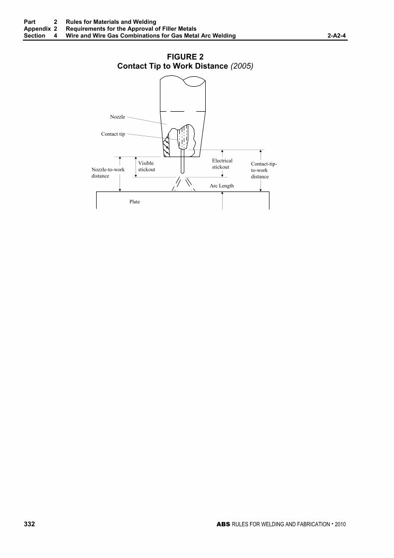
Part 2 Rules for Materials and Welding Appendix 2 Requirements for the Approval of Filler Metals Section 4 Wire and Wire Gas Combinations for Gas Metal Arc Welding 2-A2-4
332 ABS RULES FOR WELDING AND FABRICATION . 2010
FIGURE 2 Contact Tip to Work Distance (2005)
Plate
Visiblestickout
Electricalstickout Contact-tip-
to-workdistance
Arc Length
Nozzle-to-workdistance
Nozzle
Contact tip

ABS RULES FOR WELDING AND FABRICATION . 2010 333
P A R T A p p e n d i x 3 : A p p l i c a t i o n o f F i l l e r M e t a l s t o A B S S t e e l s
2 Rules for Welding and Fabrication
A P P E N D I X 3 Application of Filler Metals to ABS Steels (2009)
A chart indicating acceptable ABS filler metal grades for welding various ABS grades of hull steel is given below.
ABS Hull Structural Steel Acceptable ABS Filler Metal Grade Ordinary Strength A to 12.5 mm (1/2 in.) inclusive 1, 2, 3, 1Y**, 2Y, 3Y, 4Y A over 12.5 mm (1/2 in.), B, D 2, 3, 2Y, 3Y, 4Y E 3, 3Y, 4Y Higher Strength (2009) * AH 32/36 to 12.5 mm (1/2 in.) inclusive 1Y, 2Y**, 2Y400, 3Y, 3Y400, 4Y, 4Y400, 5Y400 AH 32/36 over 12.5 mm (1/2 in.), DH32/36 2Y, 2Y400, 3Y, 3Y400, 4Y, 4Y400, 5Y400 EH32/36 3Y, 3Y400, 4Y, 4Y400, 5Y400 FH32/36 4Y, 4Y400, 5Y400 AH40, DH40 2Y400, 3Y400, 4Y400, 5Y400 EH40 3Y400, 4Y400, 5Y400 FH40 4Y400, 5Y400 High Strength Quenched and Tempered (1997) * XQ43 ZYQ420, ZYQ460, ZYQ500 XQ47 ZYQ460, ZYQ500 XQ51 ZYQ500, ZYQ550 XQ56 ZYQ550, ZYQ620 XQ63 ZYQ620, ZYQ690 XQ70 ZYQ690
Note: For X = A or D, Z = 3, 4 and 5 For X = E, Z = 4 and 5 For X = F, Z = 5
The tensile strength range of ABS ordinary strength hull structural steel is 400-520 N/mm2, (41-53 kgf/mm2, 58-75 ksi). The tensile strength range for ABS H32/H36 higher strength hull structural steel is 440-620 N/mm2 (45-63 kgf/mm2, 64-90 ksi). For ABS H40 higher strength hull structural steel, the tensile strength range is 510-650 N/mm2 (52-66 kgf/mm2, 74-94 ksi). The ABS filler metal grades for welding ordinary and higher strength hull structural steels are assigned according to Charpy V-notch impact requirements, aimed at providing comparable levels of notch toughness of the various grades of steel. Because of inherent differences in the quality of machine automatic versus manual and manual semi-automatic produced welds, the impact strength requirements for both ordinary and higher strength filler metal grades are divided into two levels according to whether the process used is automatic or manual. The specific value requirements may be found in 2-A2-1/Table 2.
* (2008) Non-low hydrogen type electrode and wire approvals for welding higher strength steels (denoted by * in the list) are subject to satisfactory procedure tests at the user’s plant. Use of non-low hydrogen electrodes and wires on higher strength steels is limited to steels with carbon equivalent of 0.41% or less (see 2-1-3/7.1). Furthermore, these procedure tests should include fabrication of a double fillet weld assembly(ies) representative of material(s) and thickness(es) to be used in production. Weld on the first side is to be allowed to cool to ambient temperature before the second side weld is made. Three macrosections (a section from the center, and a section at one inch from each end), taken 72 hours (minimum) after welding are to be free of weld and heat affected zone cracks when etched and examined at 10X magnification.
** Grade 1Y not applicable to manual welding electrodes and semi-automatic wire-gas combinations.

334 ABS RULES FOR TESTING AND CERTIFICATION OF MATERIALS . 2010
P A R T Appendix 4: Procedure for the Approval of Manufacturers of Hull Structural Steel
2 Rules for Testing and Certification of Materials
A P P E N D I X 4 Procedure for the Approval of Manufacturers of Hull Structural Steel (2003)
CONTENTS SECTION 1 Procedure for the Approval of Manufacturers of Semi-finished
Products for Hull Structural Steel ..................................................... 336 1 Scope..............................................................................................336 3 Approval Application .......................................................................336
3.1 Documents to be Submitted ........................................................336
5 Approval Tests ................................................................................338 5.1 Extent of the Approval Tests........................................................338 5.3 Approval Test Program................................................................338 5.5 Approval Survey ..........................................................................338 5.7 Selection of the Test Product.......................................................338 5.9 Position of the Test Samples .......................................................338 5.11 Tests on Base Material ................................................................338
7 Results ............................................................................................339 9 Certification .....................................................................................339
9.1 Approval ......................................................................................339 9.3 List of Approved Manufacturers...................................................339
11 Renewal of Approval.......................................................................339 13 Withdrawal of the Approval .............................................................340
SECTION 2 Procedure for the Approval of Manufacturers of Rolled Hull
Structural Steel ................................................................................... 341 1 Scope..............................................................................................341 3 Approval Application .......................................................................341
3.1 Documents to be Submitted ........................................................341
5 Approval Tests ................................................................................343 5.1 Extent of the Approval Tests........................................................343 5.3 Approval Test Program................................................................344 5.5 Approval Survey ..........................................................................344 5.7 Selection of the Test Product.......................................................344 5.9 Position of the Test Samples .......................................................344 5.11 Tests on Base Material ................................................................344 5.13 Weldability Tests..........................................................................347
7 Results ............................................................................................347

ABS RULES FOR TESTING AND CERTIFICATION OF MATERIALS . 2010 335
9 Certification .....................................................................................348 9.1 Approval ...................................................................................... 348 9.3 List of Approved Manufacturers................................................... 348
11 Renewal of Approval.......................................................................348 13 Withdrawal of the Approval .............................................................348 TABLE 1 Tests for Rolled Products Manufacturer Approval .......................345

336 ABS RULES FOR TESTING AND CERTIFICATION OF MATERIALS . 2010
P A R T Section 1: Procedure for the Approval of Manufacturers of Semi-finished Products for Hull Structural Steel
2 A P P E N D I X 4 Procedure for the Approval of Manufacturers of
Hull Structural Steel (2003)
S E C T I O N 1 Procedure for the Approval of Manufacturers of Semi-finished Products for Hull Structural Steel (2010)
1 Scope In accordance with 2-1-1/1.2, this Section provides specific requirements for the approval of manufacturers of semi-finished products such as ingots, slabs, blooms and billets for hull structural steels. Slabs, blooms, and billets can also be supplied in the partially-rolled condition.
The manufacturer approval procedure is intended to verify the manufacturer’s capability of furnishing satisfactory products in a consistent manner under effective process and production controls in operation, as required in 2-1-1/1.2.2.
3 Approval Application
3.1 Documents to be Submitted 3.1.1 Initial Approval
The manufacturer is to submit to the Bureau request of approval together with proposed approval test program (see 2-A4-1/5.1) and general information relative to:
3.1.1(a) Name and address of the manufacturer, location of the workshops, general indications relevant to the background, dimension of the works, estimated total annual production of semi-finished products for shipbuilding and for other applications, as deemed useful.
3.1.1(b) Organization and Quality
• Organizational chart
• Staff employed
• Organization of the quality control department and its staff employed
• Qualification of the personnel involved in activities related to the quality of the products
• Certification of compliance of the quality system with IS0 9001 or 9002, if any.
• Approval certificates already granted by other Classification Societies, if any.
3.1.1(c) Manufacturing Facilities
• Flow chart of the manufacturing process
• Origin and storage of raw materials
• Storage of semi-finished products
• Equipment for systematic control during fabrication

Part 2 Rules for Materials and Welding Appendix 4 Procedure for the Approval of Manufacturers of Hull Structural Steel Section 1 Procedure for the Approval of Manufacturers of Semi-finished Products for Hull Structural
Steel 2-A4-1
ABS RULES FOR TESTING AND CERTIFICATION OF MATERIALS . 2010 337
3.1.1(d) Details of Inspections and Quality Control Facilities
• Details of system used for identification of materials at the different stages of manufacturing
• Equipment for mechanical tests, chemical analyses and metallography and relevant calibration procedures
• Equipment for nondestructive examinations
• List of quality control procedures
3.1.1(e) Type of Products (ingots, slabs, blooms, billets), Types of Steel (normal or higher strength), Range of Thickness and Target Material Properties as Follows:
• Range of chemical composition and target analyses, including grain refining, micro alloying and residual elements, for the various grades of steel; if the range of chemical composition depends on thickness and supply condition, the different ranges are to be specified, as appropriate
• Target maximum carbon equivalent according to IIW formula
• Target maximum Pcm content for higher strength grades with low carbon content C < 0.13%
• Production statistics of the chemical composition and, if available at rolling mills, mechanical properties (ReH, Rm, A% and KV). The statistics are intended to demonstrate the capability to manufacture the steel products in accordance with the requirements.
3.1.1(f) Steelmaking
• Steel making process and capacity of furnace/s or converter/s
• Raw material used
• Deoxidation and alloying practice
• Desulphurization and vacuum degassing installations, if any
• Casting methods: ingot or continuous casting. In the case of continuous casting, information relevant to type of casting machine, teeming practice, methods to prevent re-oxidation, inclusions and segregation control, presence of electromagnetic stirring, soft reduction, etc., is to be provided, as appropriate.
• Ingot or slab size and weight
• Ingot or slab treatment: scarfing and discarding procedures
3.1.1(g) Approval already granted by the other Classification Societies and documentation of approval tests performed.
3.1.1(h) Where any part of the manufacturing process is assigned to other companies or other manufacturing plants, additional information required by the Bureau is to be included.
3.1.2 Changes to the Approval Conditions Where any one or more of the following cases 2-A4-1/3.1.2(a) through 2-A4-1/3.1.2(c) are applicable, the manufacturer is to submit to the Bureau the documents required in 2-A4-1/3.1.1 together with the request of changing the approval conditions,
3.1.2(a) Change of the manufacturing process (steel making, casting, steel making plant, caster)
3.1.2(b) Change of the maximum thickness (dimension)
3.1.2(c) Change of the chemical composition, added element, etc.
However, where the documents are duplicated by the ones at the previous approval for the same type of product, part or all of the documents may be omitted, except the approval test program (see 2-A4-1/5.1).
Part 2 Rules for Materials and Welding Appendix 4 Procedure for the Approval of Manufacturers of Hull Structural Steel Section 1 Procedure for the Approval of Manufacturers of Semi-finished Products for Hull Structural
Steel 2-A4-1
338 ABS RULES FOR TESTING AND CERTIFICATION OF MATERIALS . 2010
5 Approval Tests
5.1 Extent of the Approval Tests The extent of the test program is specified in 2-A4-1/5.11. The test program may be modified on the basis of the preliminary information submitted by the manufacturer.
In particular, a reduction of the indicated number of casts, product thicknesses and types to be tested or complete omission of the approval tests may be considered, taking into account:
i) Approval already granted by other Classification Societies and documentation of approval tests performed
ii) Types of steel to be approved and availability of long-term historical statistic results of chemical properties and of mechanical properties tested on rolled products
iii) Change of the approval conditions
On the other hand, an increase of the number of casts and thicknesses to be tested may be required in the case of newly developed types of steel or manufacturing processes.
5.3 Approval Test Program Where the number of tests differs from those shown in 2-A4-1/5.11, the program is to be confirmed by the Bureau before the commencement of the tests.
5.5 Approval Survey The approval tests are to be witnessed by the Surveyor at the manufacturer’s plant. An inspection by the Surveyor of the plant in operation will be required.
If the testing facilities are not available at the works, the tests are to be carried out at recognized laboratories.
5.7 Selection of the Test Product For each type of steel and for each manufacturing process (e.g., steel making, casting), one test product with the maximum thickness (dimension) and one test product with the minimum thickness to be approved are, in general, to be selected for each kind of product (ingots, slabs, blooms/billets).
In addition, for initial approval, the Bureau will require selection of one test product of average thickness.
The selection of the casts for the test product is to be based on the typical chemical composition, with particular regard to the specified Ceq or Pcm values and grain refining micro-alloying additions.
5.9 Position of the Test Samples The test samples are to be taken, unless otherwise agreed, from the product (slabs, blooms, billets) corresponding to the top of the ingot, or, in the case of continuous casting, a random sample.
5.11 Tests on Base Material 5.11.1 Type of Tests
The tests to be carried out for the approval of the manufacturing process of semi-finished products are:
i) Chemical analysis. The analysis is to be complete including micro alloying elements.
ii) Sulphur prints.
In addition, for initial approval and for any upgrade of the approval, the Bureau will require full tests indicated in 2-A4-2/5 to be performed at rolling mill on the minimum thickness semi-finished product.

Part 2 Rules for Materials and Welding Appendix 4 Procedure for the Approval of Manufacturers of Hull Structural Steel Section 1 Procedure for the Approval of Manufacturers of Semi-finished Products for Hull Structural
Steel 2-A4-1
ABS RULES FOR TESTING AND CERTIFICATION OF MATERIALS . 2010 339
In case of a multi-caster work, full tests on finished products shall be carried out for one caster and reduced tests (chemical analysis and sulphur print) for the others. The selection of the caster shall be based on the technical characteristics of the casters to be evaluated on case by case basis to be performed at rolling mill on products manufactured from the minimum thickness semi-finished product.
5.11.2 Test Specimens and Testing Procedure The test specimens and testing procedures are to be, as a rule, in accordance with Section 2-1-1 with particular attention to the following:
5.11.2(a) Chemical Analyses. Both the ladle and product analyses are to be reported. In general, the content of the following elements is to be checked: C, Mn, Si, P, S, Ni, Cr, Mo, Al, N, Nb, V, Cu, As, Sn, Ti and, for steel manufactured from electric or open-hearth furnace, Sb and B.
5.11.2(b) Sulphur prints. Sulphur prints are to be taken from product edges which are perpendicular to the axis of the ingot or slab. These sulphur prints are to be approximately 600 mm long, taken from the center of the edge selected (i.e., on the ingot centerline) and are to include the full product thickness.
7 Results Before the approval, all test results are evaluated for compliance with the Rules. Depending upon the finding, limitations or testing conditions, as deemed appropriate, may be specified in the approval document.
All information required under 2-A4-2/3, applicable to the products submitted to the tests, is to be collected by the manufacturer and incorporated into a single document including all test results and operation records relevant to steel making, casting, and when applicable, rolling and heat treatment of the tested products.
9 Certification
9.1 Approval Upon satisfactory completion of the survey, approval will be granted by the Bureau.
The following information is to be stated on the approval certificate:
i) Type of products (ingots, slabs, blooms, billets)
ii) Steelmaking and casting processes
iii) Thickness range of the semi-finished products
iv) Types of steel (normal or higher strength)
It is also to be indicated that the individual users of the semi-finished products are to be approved for the manufacturing process of the specific grade of rolled steel products they are going to manufacture with those semi-finished products.
9.3 List of Approved Manufacturers The approved manufacturers are entered in a list containing the types of steel and the main conditions of approval.
11 Renewal of Approval The validity of the approval is to be to the maximum of five years, renewable subject to an audit and assessment of the result of satisfactory survey during the preceding period. The Surveyor’s report confirming no process changes, along with mechanical property statistical data for various approved types, is to be made available to the ABS Engineering/Materials department for review and issuance of renewal letter/certificate. *

Part 2 Rules for Materials and Welding Appendix 4 Procedure for the Approval of Manufacturers of Hull Structural Steel Section 1 Procedure for the Approval of Manufacturers of Semi-finished Products for Hull Structural
Steel 2-A4-1
340 ABS RULES FOR TESTING AND CERTIFICATION OF MATERIALS . 2010
Where for operational reasons, the renewal audit cannot be carried out within the validity of approval, the manufacturer will still be considered as being approved if agreement to such extension of audit date is provided for in the original approval. In such instance, the extension of approval will be backdated to the original renewal date.
Manufacturers who have not produced the approved types and products during the period preceding the renewal may be required to carry out approval tests, unless the results of production of similar types of products during the period are evaluated by the Bureau and found acceptable for renewal. * Note: The provisions for renewal of approval are also applicable to all grades and products which were approved by the
Bureau prior to an implementation of 2-1-1/1.2 and this Appendix, regardless of any validity of prior approval. Such renewal is to be completed before 1 January 2008, that is, within five years after the 1 January 2003 effective date of this Rule change.
13 Withdrawal of the Approval The approval may be withdrawn before the expiry of the validity period in the following cases:
i) In-service failures traceable to product quality
ii) Nonconformity of the product revealed during fabrication and construction
iii) Discovery of failure of the manufacturer’s quality system
iv) Changes made by the manufacturer, without prior agreement of the Bureau, to the extent of the approval defined at the time of the approval
v) Evidence of major nonconformities during testing of the products.

ABS RULES FOR TESTING AND CERTIFICATION OF MATERIALS . 2010 341
P A R T Section 2: Procedure for the Approval of Manufacturers of Rolled Hull Structural Steel
2 A P P E N D I X 4 Procedure for the Approval of Manufacturers of
Hull Structural Steel (2003)
S E C T I O N 2 Procedure for the Approval of Manufacturers of Rolled Hull Structural Steel (2010)
1 Scope In accordance with 2-1-1/1.2, this Appendix provides specific requirements for the approval of manufacturers of rolled hull structural steel.
The manufacturer approval procedure is intended to verify the manufacturer’s capability of furnishing satisfactory products in a consistent manner under effective process and production controls in operation including programmed rolling.
3 Approval Application
3.1 Documents to be Submitted 3.1.1 Initial Approval
The manufacturer is to submit to the Bureau request of approval together with proposed approval test program (see 2-A4-2/5.1) and general information relative to:
3.1.1(a) Name and address of the manufacturer, location of the workshops, general indications relevant to the background, dimension of the works, estimated total annual production of finished products for shipbuilding and for other applications, as deemed useful.
3.1.1(b) Organization and Quality
• Organizational chart
• Staff employed
• Organization of the quality control department and its staff employed
• Qualification of the personnel involved in activities related to the quality of the products
• Certification of compliance of the quality system with IS0 9001 or 9002, if any.
• Approval certificates already granted by other Classification Societies, if any.
3.1.1(c) Manufacturing Facilities
• Flow chart of the manufacturing process
• Origin and storage of raw materials
• Storage of finished products
• Equipment for systematic control during fabrication

Part 2 Rules for Materials and Welding Appendix 4 Procedure for the Approval of Manufacturers of Hull Structural Steel Section 2 Procedure for the Approval of Manufacturers of Rolled Hull Structural Steel 2-A4-2
342 ABS RULES FOR TESTING AND CERTIFICATION OF MATERIALS . 2010
3.1.1(d) Details of Inspections and Quality Control Facilities
• Details of system used for identification of materials at the different stages of manufacturing
• Equipment for mechanical tests, chemical analyses and metallography and relevant calibration procedures
• Equipment for non destructive examinations
• List of quality control procedures
3.1.1(e) Type of Products (plates, sections, coils), Grades of Steel, Range of Thickness and Target Material Properties as Follows:
• Range of chemical composition and aim analyses, including grain refining, micro alloying and residual elements, for the various grades of steel; if the range of chemical composition depends on thickness and supply condition, the different ranges are to be specified, as appropriate
• Target maximum carbon equivalent according to IIW formula
• Target maximum Pcm content for higher strength grades with low carbon content C < 0.13%
• Production statistics of the chemical composition and mechanical properties (ReH, Rm, A% and KV). The statistics are intended to demonstrate the capability to manufacture the steel products in accordance with the requirements.
3.1.1(f) Steelmaking
• Steel making process and capacity of furnace/s or converter/s
• Raw material used
• Deoxidation and alloying practice
• Desulphurisation and vacuum degassing installations, if any
• Casting methods: ingot or continuous casting. In the case of continuous casting, information relevant to type of casting machine, teeming practice, methods to prevent re-oxidation, inclusions and segregation control, presence of electromagnetic stirring, soft reduction, etc., is to be provided, as appropriate.
• Ingot or slab size and weight
• Ingot or slab treatment: scarfing and discarding procedures
3.1.1(g) Reheating and Rolling
• Type of furnace and treatment parameters
• Rolling: reduction ratio of slab/bloom/billet to finished product thickness, rolling and finishing temperatures
• Descaling treatment during rolling
• Capacity of the rolling stands
3.1.1(h) Heat Treatment
• Type of furnaces, heat treatment parameters and their relevant records
• Accuracy and calibration of temperature control devices
3.1.1(i) Programmed Rolling. For products delivered in the controlled rolling (CR) or thermo-mechanical rolling (TM) condition, the following additional information on the programmed rolling schedules is to be given:
• Description of the rolling process

Part 2 Rules for Materials and Welding Appendix 4 Procedure for the Approval of Manufacturers of Hull Structural Steel Section 2 Procedure for the Approval of Manufacturers of Rolled Hull Structural Steel 2-A4-2
ABS RULES FOR TESTING AND CERTIFICATION OF MATERIALS . 2010 343
• Normalizing temperature, re-crystallization temperature and Ar3 temperature and the methods used to determine them
• Control standards for typical rolling parameters used for the different thickness and grades of steel (temperature and thickness at the beginning and at the end of the passes, interval between passes, reduction ratio, temperature range and cooling speed of accelerated cooling, if any) and relevant method of control
• Calibration of the control equipment
3.1.1(j) Recommendations for working and welding, in particular, for products delivered in the CR or TM condition
• Cold and hot working recommendations, if needed, in addition to the normal practice used in the shipyards and workshops
• Minimum and maximum heat input, if different from the ones usually used in the shipyards and workshops (15 – 50 kJ/cm)
3.1.1(k) Where any part of the manufacturing process is assigned to other companies or other manufacturing plants, additional information required by the Bureau is to be included.
3.1.1(l) (2010) Approval already granted by other IACS Member Societies and documentation of approval tests performed.
3.1.2 Changes to the Approval Conditions Where any one or more of the following cases 2-A4-2/3.1.2(a) through 2-A4-2/3.1.2(e) are applicable, the manufacturer is to submit to the Bureau the documents required in 2-A4-2/3.1.1 together with the request of changing the approval conditions,
3.1.2(a) Change of the manufacturing process (steel making, casting, rolling and heat treatment)
3.1.2(b) Change of the maximum thickness (dimension)
3.1.2(c) Change of the chemical composition, added element, etc.
3.1.2(d) Subcontracting the rolling, heat treatment, etc.
3.1.2(e) (2010) Use of the slabs, blooms and billets manufactured by companies other than the ones verified in the approval tests.
However, where the documents are duplicated by the ones at the previous approval for the same type of product, part or all of the documents may be omitted, except the approval test program (see 2-A4-2/5.1).
5 Approval Tests
5.1 Extent of the Approval Tests (2010) The extent of the test program is specified in 2-A4-2/5.11 and 2-A4-2/5.13. The test program may be modified on the basis of the preliminary information submitted by the manufacturer.
In particular, a reduction of the indicated number of casts, steel plate thicknesses and grades to be tested or complete omission of the approval tests may be considered, taking into account:
i) Approval already granted by other Classification Societies and documentation of approval tests performed
ii) Grades of steel to be approved and availability of long term historical statistic results of chemical and mechanical properties
iii) Approval for any grade of steel also covers approval for any lower grade in the same strength level, provided that the target analyses, method of manufacture and condition of supply are similar.

Part 2 Rules for Materials and Welding Appendix 4 Procedure for the Approval of Manufacturers of Hull Structural Steel Section 2 Procedure for the Approval of Manufacturers of Rolled Hull Structural Steel 2-A4-2
344 ABS RULES FOR TESTING AND CERTIFICATION OF MATERIALS . 2010
iv) For higher tensile steels, approval of one strength level covers the approval of the strength level immediately below, provided the steelmaking process, deoxidation and fine grain practice, casting method and condition of supply are the same.
v) Change of the approval conditions
On the other hand, an increase of the number of casts and thicknesses to be tested may be required in the case of newly developed types of steel or manufacturing processes.
In case of multi-source slabs or changing of slab manufacturer, the rolled steel manufacturer is required to obtain the approval of the manufacturing process of rolled steels using the slabs from each slab manufacturer and to conduct approval tests in accordance with 2-A4-2/5.11 and 2-A4-2/5.13. A reduction or complete omission of the approval tests may be considered, taking into account previous approval as follows:
• The rolled steel manufacturer has already been approved for the manufacturing process using other semi-finished products characterized by the same thickness, steel grade, grain refining and micro-alloying elements, steel making and casting process;
• The semi-finished products manufacturer has been approved for the complete manufacturing process with the same conditions (steelmaking, casting, rolling and heat treatment) for the same steel types.
5.3 Approval Test Program Where the number of tests differs from those shown in 2-A4-2/5.11 and 2-A4-2/5.13, the program is to be confirmed by the Bureau before the commencement of the tests.
5.5 Approval Survey The approval tests are to be witnessed by the Surveyor at the manufacturer’s plant. An inspection by the Surveyor of the plant in operation will be required.
If the testing facilities are not available at the works, the tests are to be carried out at recognized laboratories.
5.7 Selection of the Test Product For each grade of steel and for each manufacturing process (e.g., steel making, casting, rolling and condition of supply), one test product with the maximum thickness (dimension) to be approved is, in general, to be selected for each kind of product.
In addition, for initial approval, the Bureau will require selection of one test product of average thickness.
The selection of the casts for the test product is to be based on the typical chemical composition, with particular regard to the specified Ceq or Pcm values and grain refining micro-alloying additions.
5.9 Position of the Test Samples The test samples are to be taken, unless otherwise agreed, from the product (plate, flat, section, bar) corresponding to the top of the ingot, or, in the case of continuous casting, a random sample.
The position of the samples to be taken in the length of the rolled product, “piece”, defined in 5C-8-6/2.1 (ABS), (top and/or bottom of the piece) and the direction of the test specimens with respect to the final direction of rolling of the material are indicated in 2-A4-2/Table 1.
The position of the samples in the width of the product is to be in compliance with 5C-8-6/2.2 (ABS).
5.11 Tests on Base Material 5.11.1 Type of Tests
The tests as indicated in 2-A4-2/Table 1 are to be carried out.

Part 2 Rules for Materials and Welding Appendix 4 Procedure for the Approval of Manufacturers of Hull Structural Steel Section 2 Procedure for the Approval of Manufacturers of Rolled Hull Structural Steel 2-A4-2
ABS RULES FOR TESTING AND CERTIFICATION OF MATERIALS . 2010 345
TABLE 1 Tests for Rolled Products Manufacturer Approval (2007)
Type of Test Position of the Samples and Direction of the Test Specimen (1) Remarks
Tensile test Top and bottom transverse (2) ReH, Rm, A5(%), RA(%) are to be reported
Tensile test (stress relieved) For TM steel only Top and bottom transverse (2) Stress relieving at 600°C
(2 min/mm) with minimum 1 hour) Impact tests (3) on non aged specimens for grades: Testing temperature (0°C)
A, B, AH32, AH36, AH40 +20 0 -20 D, DH32, DH36, DH40 0 -20 -40 E, EH32, EH36, EH40 0 -20 -40 -60 FH32, FH36, FH40
Top and bottom – longitudinal
-20 -40 -60 -80 A, B, AH32, AH36, AH40 +20 0 -20 D, DH32, DH36, DH40 0 -20 -40 E, EH32, E3H6, EH40 -20 -40 -60 FH32, FH36, FH40
Top – transverse (4)
-40 -60 -80 Impact tests (3) on strain aged specimens (5) for grades: Testing temperature (0°C)
AH32, AH36, AH40 +20 0 -20 D, DH32, DH36, DH40 0 -20 -40 E, EH32, EH36, EH40 -20 -40 -60 FH32, FH36, FH40
Top - longitudinal
+20 0 -80
Chemical analysis (%) (6) Top Complete analysis including micro alloying elements
Sulphur prints Top Micro examination Top Grain size determination Top For fine grain steel only
Drop weight test (4) Top For grades E, EH32, EH36, EH40, FH32, FH36, FH40 only
Through thickness tensile tests Top and bottom For grades with improved through thickness properties only
Notes: 1 For hot rolled strips see 2-A4-2/5.11.2
2 Longitudinal direction for sections and plates having width less than 600 mm
3 One set of 3 Charpy V-notch impact specimens is required for each impact test
4 Not required for sections and plates having width less than 600 mm
5 (2007) Deformation 5% + 1 hour at 250°C. The impact energy value is reported for information only.
6 Besides product analysis, ladle analysis is also required

Part 2 Rules for Materials and Welding Appendix 4 Procedure for the Approval of Manufacturers of Hull Structural Steel Section 2 Procedure for the Approval of Manufacturers of Rolled Hull Structural Steel 2-A4-2
346 ABS RULES FOR TESTING AND CERTIFICATION OF MATERIALS . 2010
5.11.2 Test Specimens and Testing Procedure The test specimens and testing procedures are to be, as a rule, in accordance with Section 2-1-1 with particular attention to the following:
5.11.2(a) Tensile Test
• For plates made from hot rolled strip, one additional tensile specimen is to be taken from the middle of the strip constituting the coil.
• For plates having thickness higher than 40 mm, when the capacity of the available testing machine is insufficient to allow the use of test specimens of full thickness, multiple flat specimens, representing collectively the full thickness, can be used. Alternatively two round specimens with the axis located at one quarter and at mid-thickness can be taken.
5.11.2(b) Impact Test
• For plates made from hot rolled strip, one additional set of impact specimens is to be taken from the middle of the strip constituting the coil.
• For plates having thickness higher than 40 mm, one additional set of impact specimens is to be taken with the axis located at mid-thickness.
• In addition to the determination of the energy value, also the lateral expansion and the percentage crystallinity are to be reported.
5.11.2(c) Chemical Analyses. Both the ladle and product analyses are to be reported. The material for the product analyses should be taken from the tensile test specimen. In general, the content of the following elements is to be checked: C, Mn, Si, P, S, Ni, Cr, Mo, Al, N, Nb, V, Cu, As, Sn, Ti and, for steel manufactured from electric or open-hearth furnace, Sb and B.
5.11.2(d) Sulphur Prints are to be taken from plate edges which are perpendicular to the axis of the ingot or slab. These sulfur prints are to be approximately 600 mm long, taken from the center of the edge selected, i.e., on the ingot centerline, and are to include the full plate thickness.
5.11.2(e) Micrographic Examination. The micrographs are to be representative of the full thickness. For thick products in general, at least three examinations are to be made at surface, one quarter and mid-thickness of the product.
All photomicrographs are to be taken at ×100 magnification and where ferrite grain size exceeds ASTM 10, additionally at ×500 magnification. Ferrite grain size should be determined for each photomicrograph.
5.11.2(f) Drop Weight Test. The test is to be performed in accordance with ASTM E208. The NDTT is to be determined and photographs of the tested specimens are to be taken and enclosed with the test report.
5.11.2(g) Through Thickness Tensile Test. The test is to be performed in accordance with 2-1-1/17.
The test results are to be in accordance, where applicable, with the requirements specified for the different steel grades in Part 2, Chapter 1.
5.11.3 Other Tests Additional tests such as CTOD test, large scale brittle fracture tests (Double Tension test, ESSO test, Deep Notch test, etc.) or other tests may be required in the case of newly developed type of steel, outside the scope of Part 2, Chapter 1, or when deemed necessary by the Bureau.

Part 2 Rules for Materials and Welding Appendix 4 Procedure for the Approval of Manufacturers of Hull Structural Steel Section 2 Procedure for the Approval of Manufacturers of Rolled Hull Structural Steel 2-A4-2
ABS RULES FOR TESTING AND CERTIFICATION OF MATERIALS . 2010 347
5.13 Weldability Tests 5.13.1 General
Weldability tests are required for plates and are to be carried out on samples of the thickest plate. Tests are required for normal strength grade E and for higher strength steels.
5.13.2 Preparation and Welding of the Test Assemblies In general the following tests are to be carried out:
i) One (1) butt weld test assembly welded with a heat input approximately 15 kJ/cm
ii) One (1) butt weld test assembly welded with a heat input approximately 50 kJ/cm.
The butt weld test assemblies are to be prepared with the weld seam transverse to the plate rolling direction, so that impact specimens will result in the longitudinal direction.
The edge preparation is preferably to be 1/2 V or K.
As far as possible, the welding procedure is to be in accordance with the normal welding practice used at the yards for the type of steel in question.
The welding parameters including consumables designation and diameter, pre-heating temperatures, interpass temperatures, heat input, number of passes, etc. are to be reported.
5.13.3 Type of Tests From the test assemblies, the following test specimens are to be taken:
5.13.3(a) One (1) cross weld tensile test
5.13.3(b) A set of three (3) Charpy V-notch impact specimens transverse to the weld with the notch located at the fusion line and at a distance 2, 5 and minimum 20 mm from the fusion line. The fusion boundary is to be identified by etching the specimens with a suitable reagent. The test temperature is to be the one prescribed for the testing of the steel grade in question.
5.13.3(c) Hardness tests HV 5 across the weldment. The indentations are to be made along a 1 mm transverse line beneath the plate surface on both the face side and the root side of the weld as follows:
• Fusion line
• HAZ: at each 0.7 mm from fusion line into unaffected base material (6 to 7 minimum measurements for each HAZ)
The maximum hardness value is to be not higher than 350 HV.
A sketch of the weld joint depicting groove dimensions, number of passes, hardness indentations is to be attached to the test report, together with photomacrographs of the weld cross section.
5.13.4 Other Tests Additional tests such as cold cracking tests (CTS, Cruciform, Implant, Tekken, Bead-on plate), CTOD, or other tests may be required in the case of newly developed type of steel, outside the scope of Part 2, Chapter 1, or when deemed necessary by the Bureau.
7 Results Before the approval, all test results are evaluated for compliance with the Rules. Depending upon the finding, limitations or testing conditions, as deemed appropriate, may be specified in the approval document.
All information required under 2-A4-2/3, applicable to the products submitted to the tests, is to be collected by the manufacturer and incorporated into a single document including all test results and operation records relevant to steel making, casting, rolling and heat treatment of the tested products.

Part 2 Rules for Materials and Welding Appendix 4 Procedure for the Approval of Manufacturers of Hull Structural Steel Section 2 Procedure for the Approval of Manufacturers of Rolled Hull Structural Steel 2-A4-2
348 ABS RULES FOR TESTING AND CERTIFICATION OF MATERIALS . 2010
9 Certification
9.1 Approval Upon satisfactory completion of the survey, approval will be granted by the Bureau.
9.3 List of Approved Manufacturers The approved manufacturers are entered in a list containing the types of steel and the main conditions of approval.
11 Renewal of Approval (2007) The validity of the approval is to be to the maximum of five years, renewable subject to an audit and assessment of the result of satisfactory survey during the preceding period. The Surveyor’s report confirming no process changes, along with mechanical property statistical data for various approved grades, is to be made available to the ABS Engineering/Materials department for review and issuance of renewal letter/ certificate. *
Where for operational reasons, the renewal audit cannot be carried out within the validity of approval, the manufacturer will still be considered as being approved if agreement to such extension of audit date is provided for in the original approval. In such instance, the extension of approval will be backdated to the original renewal date.
Manufacturers who have not produced the approved grades and products during the period preceding the renewal may be required to carry out approval tests, unless the results of production of similar grades of products during the period are evaluated by the Bureau and found acceptable for renewal. * Note: The provisions for renewal of approval are also applicable to all grades and products which were approved by the
Bureau prior to an implementation of 2-1-1/1.2 and this Appendix, regardless of any validity of prior approval. Such renewal is to be completed before 1 January 2008, that is, within five years after the 1 January 2003 effective date of this Rule change.
13 Withdrawal of the Approval The approval may be withdrawn before the expiry of the validity period in the following cases:
i) In-service failures traceable to product quality
ii) Non conformity of the product revealed during fabrication and construction
iii) Discovery of failure of the manufacturer’s quality system
iv) Changes made by the manufacturer, without prior agreement of the Bureau, to the extent of the approval defined at the time of the approval
v) Evidence of major non conformities during testing of the products.

ABS RULES FOR TESTING AND CERTIFICATION OF MATERIALS . 2010 349
P A R T Appendix 5: Procedure for the Approval of Manufacturers of Hull Structural Steels Intended for Welding with High Heat Input
2 Rules for Testing and Certification of Materials
A P P E N D I X 5 Procedure for the Approval of Manufacturers of Hull Structural Steels Intended for Welding with High Heat Input (2006)
CONTENTS 1 Scope..............................................................................................350 3 Application for Certification .............................................................350 5 Confirmation tests ...........................................................................351
5.1 Range of Certification.................................................................. 351 5.3 Weldability Test Program ............................................................ 351 5.5 Test Plate ....................................................................................351 5.7 Test Assembly.............................................................................351 5.9 Examinations and Tests for the Test Assembly........................... 352
7 Results ............................................................................................353 9 Certification .....................................................................................353 11 Grade Designation ..........................................................................353

350 ABS RULES FOR TESTING AND CERTIFICATION OF MATERIALS . 2010
P A R T
2 A P P E N D I X 5 Procedure for the Approval of Manufacturers of
Hull Structural Steels Intended for Welding with High Heat Input (2006)
1 Scope This Appendix specifies the weldability confirmation procedures of normal and higher strength hull structural steels stipulated in Sections 2-1-2 and 2-1-3 intended for welding with high heat input over 50 kJ/cm (127 kJ/in.).
The weldability confirmation proecdure is to be generally applied at manufacturer’s option and valid for certifying that the steel has satisfactory weldability for high heat input welding concerned under testing conditions.
Demonstration of conformance to the requirements of this Appendix approves a particular steel mill to manufacture grades of steel to the specific chemical composition range, melting practice, and processing practice for which conformance was established. The approval scheme does not apply to qualification of welding procedures to be undertaken by shipyards.
3 Application for Certification The manufacturer is to submit to the Bureau a request for certification of the proposed weldability test program (see 2-A5/5.3 below) and technical documents relevant to:
i) Outline of steel plate to be certified
• Grade
• Thickness range
• Deoxidation practice
• Fine grain practice
• Aim range of chemical composition
• Aim maximum Ceq and Pcm
• Production statistics of mechanical properties (tensile and Charpy V-notch impact tests), if any
ii) Manufacturing control points to prevent toughness deterioration in heat affected zones of high heat input welds, relevant to chemical elements, steel making, casting, rolling, heat treatment etc.
iii) Welding control points to improve joint properties on strength and toughness.
Part 2 Rules for Materials and Welding Appendix 5 Procedure for the Approval of Manufacturers of Hull Structural Steels Intended
for Welding with High Heat Input 2-A5
ABS RULES FOR TESTING AND CERTIFICATION OF MATERIALS . 2010 351
5 Confirmation tests
5.1 Range of Certification Range of certification for steel grades is to be in accordance with the following, unless otherwise agreed by the Bureau:
i) Approval tests on the lowest and highest toughness levels cover the intermediate toughness level.
ii) Approval tests on normal strength level cover that strength level only.
iii) For high tensile steels, approval tests on one strength level cover strength level immediately below.
iv) Tests may be carried out separately provided the same manufacturing process is applied.
v) Certification and documentation of confirmation tests performed by another Classification Society may be accepted at the discretion of the Bureau.
5.3 Weldability Test Program The extent of the test program is specified in 2-A5/5.9, but it may be modified according to the contents of certification. In particular, additional test assemblies and/or test items may be required in the case of newly developed types of steel, welding consumable and welding method, or when deemed necessary by the Bureau. Where the content of tests differs from those specified in 2-A5/5.9, the program is to be confirmed by the Bureau before the tests are carried out.
5.5 Test Plate The test plate is to be manufactured by a process approved by the Bureau in accordance with the requirements of Part 2, Appendix 4. For each manufacturing process route, two test plates with different thickness are to be selected. The thicker plate (t) and thinner plate (less than or equal to t/2) are to be proposed by the manufacturer.
Minor changes in manufacturing processing (e.g. within the TMCP process) may be considered for acceptance without testing, at the discretion of the Bureau.
5.7 Test Assembly One butt weld assembly welded with heat input over 50 kJ/cm is generally to be prepared with the weld axis transverse to the plate rolling direction.
Dimensions of the test assembly are to be amply sufficient to take all the required test specimens specified in 2-A5/5.5.
The welding procedures should be as far as possible in accordance with the normal practices applied at shipyards for the test plate concerned, and including the following:
• Welding process
• Welding position
• Welding consumable (manufacturer, brand, grade, diameter and shield gas)
• Welding parameters including bevel preparation, heat input, preheating temperatures, interpass temperatures, number of passes, etc.

Part 2 Rules for Materials and Welding Appendix 5 Procedure for the Approval of Manufacturers of Hull Structural Steels Intended
for Welding with High Heat Input 2-A5
352 ABS RULES FOR TESTING AND CERTIFICATION OF MATERIALS . 2010
5.9 Examinations and Tests for the Test Assembly The test assembly is to be examined and tested in accordance with the following, unless otherwise agreed by the Bureau.
i) Visual examination. Overall welded surface is to be uniform and free from injurious defects such as cracks, undercuts, overlaps, etc.
ii) Macroscopic test. One macroscopic photograph is to be representative of transverse section of the welded joint and is to show absence of cracks, lack of penetration, lack of fusion and other injurious defects.
iii) Microscopic test. Along mid-thickness line across transverse section of the weld, one micrograph with ×100 magnification is to be taken at each position of the weld metal centerline, fusion line and at a distance 2, 5, 10 and a minimum 20 mm (0.8 in.) from the fusion line. The test result is provided for information purpose only.
iv) Hardness test. Along two lines across transverse weld section 1 mm beneath plate surface on both face and root side of the weld, indentations by HV5 are to be made at weld metal centerline, fusion line and each 0.7 mm (0.28 in.) position from fusion line to unaffected base metal (minimum 6 to 7 measurements for each heat affected zone). The maximum hardness value should not be higher than 350 HV.
v) Transverse tensile test. Two transverse (cross weld) tensile specimens are to be taken from the test assembly. Test specimens and testing procedures are to comply with the requirements of Section 2-4-3.
The tensile strength is to be not less than the minimum required value for the grade of base metal.
vi) Bend test. Two transverse (cross weld) test specimens are to be taken from the test assembly and bent on a mandrel with diameter of quadruple specimen thickness. Bending angle is to be at least 120 degrees. Test specimens are to comply with the requirements of Section 2-4-3.
For plate thickness up to 20 mm (0.8 in.), one face-bend and one root-bend specimens or two side-bend specimens are to be taken. For plate thickness over 20 mm (0.8 in.), two side-bend specimens are to be taken. After testing, the test specimens shall not reveal any crack nor other open defect in any direction greater than 3 mm (0.12 in.).
vii) Impact test. Charpy V-notch impact specimens (three specimens for one set) are to be taken within 2 mm (0.08 in.) below plate surface on face side of the weld with the notch perpendicular to the plate surface.
One set of the specimens transverse to the weld is to be taken with the notch located at the fusion line and at a distance 2, 5 and a minimum 20 mm (0.8 in.) from the fusion line. The fusion boundary is to be identified by etching the specimens with a suitable reagent. The test temperature is to be the one prescribed for the testing of the steel grade in question.
For steel plate with thickness greater than 50 mm (2.0 in.) or one side welding for plate thickness greater than 20 mm (0.8 in.), one additional set of the specimens is to be taken from the root side of the weld with the notch located at each of the same positions as for the face side.
The average impact energy at the specified test temperature is to comply with the requirements of 2-1-2/Table 4 or 2-1-3/Table 4, depending on the steel grade and thickness. Only one individual value may be below the specified average value provided it is not less than 70% of that value. Additional tests at the different testing temperatures may be required for evaluating the transition temperature curve of absorbed energy and percentage crystallinity at the discretion of the Bureau.
viii) Other tests. Additional tests, such as wide-width tensile test, HAZ tensile test, cold cracking tests (CTS, Cruciform, Implant, Tekken, and Bead-on plate), CTOD or other tests may be required at the discretion of the Bureau (see 2-A5/5.3).

Part 2 Rules for Materials and Welding Appendix 5 Procedure for the Approval of Manufacturers of Hull Structural Steels Intended
for Welding with High Heat Input 2-A5
ABS RULES FOR TESTING AND CERTIFICATION OF MATERIALS . 2010 353
7 Results The manufacturer is to submit to the Bureau the complete test report including all the results and required information relevant to the confirmation tests specified in 2-A5/5.
The contents of the test report are to be reviewed and evaluated by the Bureau in accordance with this weldability confirmation scheme.
9 Certification The Bureau will issue a certificate where the test report is found to be satisfactory. The following information is to be included on the certificate:
i) Manufacturer
ii) Grade designation with notation of heat input (refer to 2-A5/11)
iii) Deoxidation practice
iv) Fine grain practice
v) Condition of supply
vi) Plate thickness tested
vii) Welding process
viii) Welding consumable (manufacturer, brand, grade).
ix) Actual heat input applied.
11 Grade Designation Upon issuance of the certificate, the notation indicating the value of heat input applied in the confirmation test may be added to the grade designation of the test plate, e.g. “E36-W300” [in the case of heat input 300 kJ/cm (762 kJ/in.) applied]. The value of this notation is to be not less than 50 and every 10 added.

354 ABS RULES FOR TESTING AND CERTIFICATION OF MATERIALS . 2010
P A R T Appendix 6: Guide for Nondestructive Examination of Marine Steel Castings
2 Rules for Testing and Certification of Materials
A P P E N D I X 6 Guide for Nondestructive Examination of Marine Steel Castings (2005)
CONTENTS SECTION 1 General ................................................................................................ 356
1 Scope..............................................................................................356 SECTION 2 Surface Inspection ............................................................................. 357
1 General ...........................................................................................357 3 Products ..........................................................................................357 5 Location for Surface Inspections ....................................................357 7 Surface Condition ...........................................................................358 9 Surface Inspection ..........................................................................358 11 Acceptance Criteria and Rectification of Defects............................358
11.1 Acceptance Criteria – Visual Inspection ......................................358 11.3 Acceptance Criteria – Magnetic Particle Testing and Liquid
Penetrant Testing ........................................................................359 11.5 Rectification of Defects ................................................................359
13 Record.............................................................................................360 TABLE 1 Allowable Number and Size of Indications in a Reference
Band Length/Area .................................................................361 SECTION 3 Volumetric Inspection ........................................................................ 362
1 General ...........................................................................................362 3 Products ..........................................................................................362 5 Location for Volumetric Inspection..................................................362 7 Surface Condition ...........................................................................363 9 Acceptance Criteria.........................................................................363 11 Record.............................................................................................363 TABLE 1 Acceptance Criteria for Steel Castings .................................364

ABS RULES FOR TESTING AND CERTIFICATION OF MATERIALS . 2010 355
ANNEX 1 General Location for the Type of Nondestructive Examinations of Typical Hull Steel Castings ........................................................... 365 FIGURE 1 Stern Frame ..........................................................................365 FIGURE 2 Rudder stock .........................................................................366 FIGURE 3 Stern Boss.............................................................................367 FIGURE 4 Rudder Hangings ..................................................................368 FIGURE 5 Rudder (Upper Part) .............................................................369 FIGURE 6 Rudder (Lower Part) .............................................................370

356 ABS RULES FOR TESTING AND CERTIFICATION OF MATERIALS . 2010
P A R T S e c t i o n 1 : G e n e r a l
2 A P P E N D I X 6 Guide for Nondestructive Examination of Marine
Steel Castings
S E C T I O N 1 General
Note: The requirements in this Appendix have been adopted from the IACS Recommendation No. 69. “Guidelines for Non-destructive Examination of Marine Steel Castings”. However, in order to be consistent with existing ABS publications, some specific text from the above referenced Guidelines has been modified. This Appendix incorporates the ABS Guide for Nondestructive Examination of Marine Steel Castings, which is effective as of 1 January 2005.
1 Scope
1.1 This Guide contains general guidance for the nondestructive examination methods, the extent of examination and the minimum recommended quality levels to be complied with for marine steel castings, unless otherwise approved or specified.
1.3 This document contains guidelines on “Surface Inspections” (Section 2-A6-2) by visual examination, magnetic particle testing and liquid penetrant testing and “Volumetric Inspection” (Section 2-A6-3) by ultrasonic testing and radiographic testing.
1.5 Although no detailed guidelines are given for machinery components, the requirements in this Guide may apply correspondingly considering their materials, kinds, shapes and stress conditions being subjected.
1.7 Castings should be examined in the final delivery condition. For specific requirements, see 2-A6-2/9.3 and 2-A6-3/7.3.
1.9 Where intermediate inspections have been performed the manufacturer is to furnish the documentation of the results upon request of the Surveyor.

ABS RULES FOR TESTING AND CERTIFICATION OF MATERIALS . 2010 357
P A R T S e c t i o n 2 : S u r f a c e I n s p e c t i o n
2 A P P E N D I X 6 Guide for Nondestructive Examination of Marine
Steel Castings
S E C T I O N 2 Surface Inspection
1 General
1.1 Surface inspections in this Guide are to be carried out by visual examination and magnetic particle testing or liquid penetrant testing.
1.3 The testing procedures, apparatus and conditions of magnetic particle testing and liquid penetrant testing are to comply with a recognized national or international standard.
1.5 Personnel engaged in visual examination are to have sufficient knowledge and experience. Personnel engaged in magnetic particle testing or liquid penetrant testing are to be qualified in accordance with the ABS Guide for Nondestructive Inspection of Hull Welds. The qualification is to be verified by the certificates.
3 Products
3.1 Steel castings are to be subjected to a 100% visual examination of all accessible surfaces by the Surveyor.
3.3 Surface inspections by magnetic particle and/or liquid penetrant methods apply to the hull steel castings indicated in Annex 1 of this Appendix.
5 Location for Surface Inspections
5.1 Surface inspections are to be carried out in the following locations:
• At all accessible fillets and changes of section
• At positions where surplus metal has been removed by flame cutting, scarfing or arc-air gouging
• In way of fabrication weld preparation, for a band width of 30 mm
• In way of weld repairs

Part 2 Rules for Materials and Welding Appendix 6 Guide for Nondestructive Examination of Marine Steel Castings Section 2 Surface Inspection 2-A6-2
358 ABS RULES FOR TESTING AND CERTIFICATION OF MATERIALS . 2010
5.3 The following quality levels are considered for magnetic particle testing (MT) and/or liquid penetrant testing (PT):
• Level MT1/PT1 – fabrication weld preparation and weld repairs.
• Level MT2/PT2 – other locations shown in 2-A6-2/5.1.
The required quality level is to be shown on the manufacturer’s drawings.
7 Surface Condition The surfaces of castings to be examined are to be free from scale, dirt, grease or paint and are to be shot blasted or ground.
9 Surface Inspection
9.1 Magnetic particle inspection will be carried out with the following exceptions, when liquid penetrant testing will be permitted:
• Austenitic stainless steels
• Interpretation of open visual or magnetic particle indications
• At the instruction of the Surveyor
9.3 Unless otherwise specified in the order, the magnetic particle test is to be performed on a casting in the final delivery condition and final thermally treated condition or within 0.3 mm of the final machined surface condition for AC techniques (0.8 mm for DC techniques).
9.5 Unless otherwise agreed, the surface inspection is to be carried out in the presence of the Surveyor.
9.7 For magnetic particle testing, attention is to be paid to the contact between the casting and the clamping devices of stationary magnetization benches in order to avoid local overheating or burning damage in its surface. Prods are not permitted on finished machined items.
9.9 When indications are detected as a result of the surface inspection, the acceptance or rejection is to be decided in accordance with 2-A6-2/11.
11 Acceptance Criteria and Rectification of Defects
11.1 Acceptance Criteria – Visual Inspection All castings are to be free of cracks, crack-like indications, hot tears, laps, seams, folds or other injurious indications. Thickness of the remains of sprues, heads or burrs is to be within the casting dimensional tolerance. Additional magnetic particle, liquid penetrant and ultrasonic testing may be required for a more detailed evaluation of surface irregularities at the request of the surveyor.

Part 2 Rules for Materials and Welding Appendix 6 Guide for Nondestructive Examination of Marine Steel Castings Section 2 Surface Inspection 2-A6-2
ABS RULES FOR TESTING AND CERTIFICATION OF MATERIALS . 2010 359
11.3 Acceptance Criteria – Magnetic Particle Testing and Liquid Penetrant Testing 11.3.1
The following definitions relevant to indications apply:
• Linear indication. An indication in which the length is at least three times the width.
• Nonlinear indication. An indication of circular or elliptical shape with a length less than three times the width.
• Aligned indication. Three or more indications in a line, separated by 2 mm or less edge-to-edge.
• Open indication. An indication visible after removal of the magnetic particles or that can be detected by the use of contrast dye penetrant.
• Non-open indication. An indication that is not visually detectable after removal of the magnetic particles or that cannot be detected by the use of contrast dye penetrant.
• Relevant indication. An indication that is caused by a condition or type of discontinuity that requires evaluation. Only indications which have any dimension greater than 1.5 mm are to be considered relevant.
11.3.2 For the purpose of evaluating indications, the surface is to be divided into reference band length of 15 cm for level MT1/PT1 and into reference areas of 225 cm2 for level MT2/PT2. The band length and/or area is to be taken in the most unfavorable location relative to the indication being evaluated.
11.3.3 The allowable number and size of indications in the reference band length and/or area is given in 2-A6-2/Table 1. Cracks and hot tears are not acceptable.
11.5 Rectification of Defects Defects and unacceptable indications are to be repaired as indicated below and detailed in 2-A6-2/11.5.2.
11.5.1 Defective parts of material may be removed by grinding, or by chipping and grinding, or by arc air-gouging and grinding. All grooves are to have a bottom radius of approximately three times the groove depth and should be smoothly blended to the surface area with a finish equal to the adjacent surface.
11.5.2 Repairs by welding are defined as follows:
Major repairs:
• Where the depth is greater than 25% of the wall thickness or 2.5 cm whichever is the less, or
• Where the weld area (length X width) exceeds 1250 cm2 (Note: where a distance between two welds is less than their average width, they are considered as one weld), or
• Where the total weld area on a casting exceeds 2% of the casting surface.
Minor repairs:
• Where the total weld area (length X width) exceeds 5 cm2.
Cosmetic repairs:
• All other welds.

Part 2 Rules for Materials and Welding Appendix 6 Guide for Nondestructive Examination of Marine Steel Castings Section 2 Surface Inspection 2-A6-2
360 ABS RULES FOR TESTING AND CERTIFICATION OF MATERIALS . 2010
11.5.2(a) Major repairs are to be approved before the repair is carried out. The repair should be carried out before final furnace heat treatment.
11.5.2(b) Minor repairs do not require approval before the repair is carried out but should be recorded on a weld repair sketch as a part of the manufacturing procedure documents. These repairs should be carried out before final furnace heat treatment.
11.5.2(c) Cosmetic repairs do not require approval before the repair is carried out but should be recorded on a weld repair sketch. These repairs may be carried out after final furnace heat treatment but are subject to a local stress relief heat treatment. Thermal methods of metal removal should only be allowed before the final heat treatment. After final heat treatment only grinding or chipping and grinding should be al-lowed. Weld repairs should be suitably classified.
Parts which are repaired should be examined by the same method as at initial inspection as well as by additional methods as required by the Surveyor.
13 Record
13.1 Test results of surface inspections are to be recorded at least with the following items:
i) Date of testing
ii) Names and qualification level of inspection personnel
iii) Kind of testing method
• For liquid penetrant testing: test media combination
• For magnetic particle testing: method of magnetizing, test media and magnetic field strength
iv) Kind of product
v) Product number for identification
vi) Grade of steel
vii) Heat treatment
viii) Stage of testing
ix) Locations for testing
x) Surface condition
xi) Test standards used
xii) Testing condition
xiii) Results
xiv) Statement of acceptance/non acceptance
xv) Details of weld repair including sketch

Part 2 Rules for Materials and Welding Appendix 6 Guide for Nondestructive Examination of Marine Steel Castings Section 2 Surface Inspection 2-A6-2
ABS RULES FOR TESTING AND CERTIFICATION OF MATERIALS . 2010 361
TABLE 1 Allowable Number and Size of Indications in a Reference Band Length/Area
Quality Level Max. Number of Indications
Type of Indication Max. Number for Each Type
Max. Dimension (mm) (2)
Linear 4 (1) 5 Nonlinear 4 (1) 3 MT1/PT1 4
in a 15 cm length Aligned 4 (1) 3 Linear 10 7
Nonlinear 6 5 MT2/PT2 20 in a 225 cm2 area
Aligned 6 5
Notes 1 30 mm min. between relevant indications.
2 In weld repairs, max. dimension < 2 mm.

362 ABS RULES FOR TESTING AND CERTIFICATION OF MATERIALS . 2010
P A R T S e c t i o n 3 : V o l u m e t r i c I n s p e c t i o n
2 A P P E N D I X 6 Guide for Nondestructive Examination of Marine
Steel Castings
S E C T I O N 3 Volumetric Inspection
1 General
1.1 Volumetric inspection in this Guide is to be carried out by ultrasonic testing using the contact method with straight beam and/or angle beam technique.
1.3 The testing procedures, apparatus and conditions of ultrasonic testing are to comply with the recognized national or international standards. Generally, the DGS (distance-gain size) procedure is to be applied using straight beam probes and/or angle beam probes with 1 to 4 MHz and an inspection should be carried out using a twin crystal 0° probe for near surface scans (25 mm) plus a 0° probe for the remaining volume. Fillet radii should be examined using 45°, 60° or 70° probes.
1.5 Radiographic testing is to be carried out in accordance with an approved plan.
1.7 Personnel engaged in ultrasonic or radiographic testing is to be qualified in accordance with the ABS Guide for Nondestructive Inspection of Hull Welds. The qualification is to be verified by certificates.
3 Products
3.1 Volumetric inspection by ultrasonic or radiographic testing apply to the hull steel castings indicated in Annex 1 of this Appendix.
5 Location for Volumetric Inspection
5.1 Volumetric inspection is to be carried out according to the inspection plan. The inspection plan should specify the extent of the examination, the examination procedure, the quality level or, if necessary, levels for different locations of the castings. The inspection plan is to be approved.
5.3 Ultrasonic testing is to be carried out in the following locations:
• In way of all accessible fillets and changes of section
• In way of fabrication weld preparation for a distance of 50 mm from the edge
• At all locations to be subject to subsequent machining (including bolt holes)
• In way of weld repairs where original defect was detected by ultrasonic testing

Part 2 Rules for Materials and Welding Appendix 6 Guide for Nondestructive Examination of Marine Steel Castings Section 3 Volumetric Inspection 2-A6-3
ABS RULES FOR TESTING AND CERTIFICATION OF MATERIALS . 2010 363
5.5 The following quality levels are considered for ultrasonic testing (UT):
Level UT1:
• Fabrication weld preparation for a distance of 50 mm
• 50 mm depth from the final machined surface including bolt holes
• Fillet radii for a depth of 50 mm and within distance of 50 mm from the radius end
Level UT2:
• Other locations.
The required quality levels are to be shown on the manufacturer’s drawings.
7 Surface Condition
7.1 The surfaces of castings to be examined are to be such that adequate coupling can be established between the probe and the casting and that excessive wear of the probe can be avoided. The surfaces are to be free from scale, dirt, grease or paint.
7.3 The ultrasonic testing is to be carried out after the steel castings have been machined to a condition suitable for this type of testing and after the final heat treatment. Black castings are to be inspected after removal of the oxide scale by either flame descaling or shot blasting methods.
9 Acceptance Criteria Acceptance criteria of volumetric inspection by ultrasonic testing are shown in 2-A6-3/Table 1.
11 Record Test results of volumetric inspection are to be recorded at least with the following items:
i) Date of testing
ii) Names and qualification level of inspection personnel
iii) Kind of testing method
iv) Kind of product
v) Product number for identification
vi) Grade of steel
vii) Heat treatment
viii) Stage of testing
ix) Locations for testing
x) Surface condition
xi) Test standards used
xii) Testing condition
xiii) Results
xiv) Statement of acceptance/non acceptance

Part 2 Rules for Materials and Welding Appendix 6 Guide for Nondestructive Examination of Marine Steel Castings Section 3 Volumetric Inspection 2-A6-3
364 ABS RULES FOR TESTING AND CERTIFICATION OF MATERIALS . 2010
TABLE 1 Acceptance Criteria for Steel Castings
Quality Level (1) Allowable Disk Shape According to DGS (2)
Max. Number of Indications to be
Registered
Allowable Length of Linear Indications
(mm) UT1 6 3 10 UT2 12 5 50
Notes 1 For the castings subject to cyclic bending stresses, e.g., rudder horn, rudder castings and
rudder stocks, the outer one third of thickness is to comply with the acceptance criteria for level UT 1.
2 DGS: distance – gain size.

ABS RULES FOR TESTING AND CERTIFICATION OF MATERIALS . 2010 365
P A R T Annex 1: General Location for the Type of Nondestructive Examinations of Typical Hull Steel Castings
2 A P P E N D I X 6 Guide for Nondestructive Examination of Marine
Steel Castings
A N N E X 1 General Location for the Type of Nondestructive Examinations of Typical Hull Steel Castings
FIGURE 1 Stern Frame
Notes:
Location of nondestructive examination:
1 All surfaces: Visual examination
2 Location indicated with (OOO): Magnetic particle testing and ultrasonic testing
3 The detailed extents of examinations and quality levels are given in Sections 2-A6-2 and 2-A6-3.

Part 2 Rules for Materials and Welding Appendix 6 Guide for Nondestructive Examination of Marine Steel Castings Annex 1 General Location for the Type of Nondestructive Examinations of Typical Hull Steel
Castings 2-A6-A1
366 ABS RULES FOR TESTING AND CERTIFICATION OF MATERIALS . 2010
FIGURE 2 Rudder stock
A
AB B
A-A B-B
Notes: Location of nondestructive examination:
1 All surfaces: Visual examination.
Magnatic particle testing and Ultrasonic testing.
2 The detailed extents of examinations and quality levels are given in Sections 2-A6-2 and 2-A6-3.

Part 2 Rules for Materials and Welding Appendix 6 Guide for Nondestructive Examination of Marine Steel Castings Annex 1 General Location for the Type of Nondestructive Examinations of Typical Hull Steel
Castings 2-A6-A1
ABS RULES FOR TESTING AND CERTIFICATION OF MATERIALS . 2010 367
FIGURE 3 Stern Boss
a
a
Notes:
Location of nondestructive examination:
1 All surfaces: Visual examination
2 Location indicated with (OOO): Magnetic particle testing and Ultrasonic testing
3 Location indicated with (^^^^): Ultrasonic testing
4 The detailed extents of examinations and quality levels are given in Sections 2-A6-2 and 2-A6-3.

Part 2 Rules for Materials and Welding Appendix 6 Guide for Nondestructive Examination of Marine Steel Castings Annex 1 General Location for the Type of Nondestructive Examinations of Typical Hull Steel
Castings 2-A6-A1
368 ABS RULES FOR TESTING AND CERTIFICATION OF MATERIALS . 2010
FIGURE 4 Rudder Hangings
AA
Wr 4
Wr 3
Wr 2
Wr 1
A-A
Notes:
Location of nondestructive examination:
1 All surfaces: Visual examination
2 Location indicated with (OOO): Magnetic particle testing and Ultrasonic testing
3 Location indicated with (^^^^): Ultrasonic testing 4 The detailed extents of examinations and quality levels are given in Sections 2-A6-2 and 2-A6-3.

Part 2 Rules for Materials and Welding Appendix 6 Guide for Nondestructive Examination of Marine Steel Castings Annex 1 General Location for the Type of Nondestructive Examinations of Typical Hull Steel
Castings 2-A6-A1
ABS RULES FOR TESTING AND CERTIFICATION OF MATERIALS . 2010 369
FIGURE 5 Rudder (Upper Part)
Notes:
Location of nondestructive examination:
1 All surfaces: Visual examination
2 Location indicated with (OOO): Magnetic particle testing and Ultrasonic testing
3 Location indicated with (^^^^): Ultrasonic testing
4 The detailed extents of examinations and quality levels are given in Sections 2-A6-2 and 2-A6-3.

Part 2 Rules for Materials and Welding Appendix 6 Guide for Nondestructive Examination of Marine Steel Castings Annex 1 General Location for the Type of Nondestructive Examinations of Typical Hull Steel
Castings 2-A6-A1
370 ABS RULES FOR TESTING AND CERTIFICATION OF MATERIALS . 2010
FIGURE 6 Rudder (Lower Part)
A
AA
B
A
B Notes:
Location of nondestructive examination:
1 All surfaces: Visual examination
2 Location indicated with (OOO): Magnetic particle testing and Ultrasonic testing
3 Location indicated with (^^^^): Ultrasonic testing
4 The detailed extents of examinations and quality levels are given in Sections 2-A6-2 and 2-A6-3.

ABS RULES FOR TESTING AND CERTIFICATION OF MATERIALS . 2010 371
P A R T Appendix 7: Guide for Nondestructive Examination of Hull and Machinery Steel Forgings
2 Rules for Testing and Certification of Materials
A P P E N D I X 7 Guide for Nondestructive Examination of Hull and Machinery Steel Forgings (2005)
CONTENTS SECTION 1 General................................................................................................ 373
1 Scope..............................................................................................373 SECTION 2 Surface Inspection ............................................................................. 374
1 General ...........................................................................................374 3 Products..........................................................................................374 5 Zones for Surface Inspections ........................................................374 7 Surface Condition ...........................................................................375 9 Surface Inspection ..........................................................................375 11 Acceptance Criteria and Rectification of Defects ...........................375
11.1 Acceptance Criteria Visual Inspection ......................................... 375 11.3 Acceptance Criteria Magnetic Particle Testing and Liquid
Penetrant Testing ........................................................................ 375 11.5 Rectification of Defects................................................................ 377
13 Record.............................................................................................377 TABLE 1 Crankshaft Forgings: Allowable Number and Size of
Indications in a Reference Area of 225 cm2..........................376 TABLE 2 Steel Forgings: Excluding Crankshaft Forgings Allowable
Number and Size of Indications in a Reference Area of 225 cm2 .................................................................................376
FIGURE 1 Zones for Magnetic Particle/Liquid Penetrant Testing on
Crankshafts ...........................................................................379 FIGURE 2 Zones for Magnetic Particle/Liquid Penetrant Testing on
Shafts ....................................................................................380 FIGURE 3 Zones for Magnetic Particle/Liquid Penetrant Testing on
Machinery Components ........................................................381 FIGURE 4 Zones for Magnetic Particle/Liquid Penetrant Testing on
Rudder Stocks.......................................................................382

372 ABS RULES FOR TESTING AND CERTIFICATION OF MATERIALS . 2010
SECTION 3 Volumetric Inspection ........................................................................ 383 1 General ...........................................................................................383 3 Products ..........................................................................................383 5 Zones for Volumetric Inspection .....................................................383 7 Surface Condition ...........................................................................384 9 Acceptance Criteria.........................................................................384 11 Record.............................................................................................384 TABLE 1 Acceptance Criteria for Crankshafts .....................................385 TABLE 2 Acceptance Criteria for Shafts and Machinery
Components..........................................................................385 FIGURE 1 Zones for Ultrasonic Testing on Crankshafts........................386 FIGURE 2 Zones for Ultrasonic Testing on Shafts.................................387 FIGURE 3 Zones for Ultrasonic Testing on Machinery Components.....388 FIGURE 4 Zones for Ultrasonic Testing on Rudder Stocks ...................389

ABS RULES FOR TESTING AND CERTIFICATION OF MATERIALS . 2010 373
P A R T S e c t i o n 1 : G e n e r a l
2 A P P E N D I X 7 Guide for Nondestructive Examination of Hull
and Machinery Steel Forgings
S E C T I O N 1 General
Note: This Appendix incorporates the ABS Guide for Nondestructive Examination of Marine Steel Castings, which is effective as of 1 January 2005. The requirements in the Guide have been adopted from the IACS Recommendation No. 68. “Guidelines for Non-destructive Examination of Hull and Machinery Steel Forgings”. However, in order to be consistent with existing ABS publications, some specific text from the above referenced Guidelines has been modified.
1 Scope
1.1 This Guide complements the ABS requirements for “Hull and machinery steel forgings” and “Parts of internal combustion engines for which non-destructive tests are required”, and contains general guidance for the nondestructive examination methods, the extent of examination and the minimum recommended quality levels to be complied with unless otherwise approved or specified.
1.3 This document contains guidelines on “Surface Inspections” (Section 2-A7-2) by visual examination, magnetic particle testing and liquid penetrant testing and “Volumetric Inspection” (Section 2-A7-3) by ultrasonic testing.
1.5 For steel forgings (e.g., components for couplings, gears, boilers and pressure vessels) other than those specified in this Guide, the requirements in this Guide may apply correspondingly considering their materials, kinds, shapes and stress conditions being subjected.
1.7 Forgings should be examined in the final delivery condition. For specific requirements, see 2-A7-2/9.3 and 2-A7-3/7.3.
1.9 Where intermediate inspections have been performed, the manufacturer is to furnish a documentation of the results upon the request of the Surveyor.
1.11 Where a forging is supplied in semi-finished condition, the manufacturer is to take into consideration the quality level of final finished machined components.

374 ABS RULES FOR TESTING AND CERTIFICATION OF MATERIALS . 2010
P A R T S e c t i o n 2 : S u r f a c e I n s p e c t i o n
2 A P P E N D I X 7 Guide for Nondestructive Examination of Hull
and Machinery Steel Forgings
S E C T I O N 2 Surface Inspection
1 General
1.1 Surface inspections in this Guide are to be carried out by visual examination and magnetic particle testing or liquid penetrant testing.
1.3 The testing procedures, apparatus and conditions of magnetic particle testing and liquid penetrant testing are to comply with a recognized national or international standard.
1.5 Personnel engaged in visual examination are to have sufficient knowledge and experience. Personnel engaged in magnetic particle testing or liquid penetrant testing are to be qualified in accordance with the ABS Guide for Nondestructive Inspection of Hull Welds. The qualification is to be verified by certificates.
3 Products
3.1 The steel forgings intended for hull and machinery applications such as rudder stocks, pintles, propeller shafts, crankshafts, connecting rids, piston rods, gearing, etc. are to be subjected to a 100% visual examination by the Surveyor. For mass produced forgings the extent of examination is to be established at the discretion of the attending Surveyor.
3.3 Surface inspections by magnetic particle and/or liquid penetrant methods generally apply to the following steel forgings:
i) Crankshafts with minimum crankpin diameter not less than 100 mm
ii) Propeller shafts, intermediate shafts, thrust shafts and rudder stocks with minimum diameter not less than 100 mm
iii) Connecting rods, piston rods and crosshead with minimum diameter not less than 75 mm or equivalent cross section
iv) Bolts with minimum diameter not less than 50 mm, which are subjected to dynamic stresses such as cylinder cover bolts, tie rods, crankpin bolts, main bearing bolts, propeller blade fastening bolts
5 Zones for Surface Inspections Magnetic particle, or where permitted, liquid penetrant testing, is to be carried out in the zones I and II as indicated in 2-A7-2/Figures 1 to 4.

Part 2 Rules for Materials and Welding Appendix 7 Guide for Nondestructive Examination of Hull and Machinery Steel Forgings Section 2 Surface Inspection 2-A7-2
ABS RULES FOR TESTING AND CERTIFICATION OF MATERIALS . 2010 375
7 Surface Condition The surfaces of forgings to be examined are to be free from scale, dirt, grease or paint.
9 Surface Inspection
9.1 Where indicated by Section 2, Figures 1 to 4, magnetic particle inspections are to be carried out with the following exceptions, when liquid penetrant testing will be permitted:
• Austenitic stainless steels
• Interpretation of open visual or magnetic particle indications
• At the instruction of the Surveyor
9.3 Unless otherwise specified in the order, the magnetic particle test is to be performed on a forging in the final machined surface condition and final thermally treated condition or within 0.3 mm of the final machined surface condition for AC techniques (0.8 mm for DC techniques).
9.5 Unless otherwise agreed, the surface inspection is to be carried out in the presence of the Surveyor. The surface inspection is to be carried out before the shrink fitting, where applicable.
9.7 For magnetic particle testing, attention is to be paid to the contact between the forging and the clamping devices of stationary magnetization benches in order to avoid local overheating or burning damage in its surface. Prods are not permitted on finished machined items.
9.9 When indications are detected as a result of the surface inspection, the acceptance or rejection is to be decided in accordance with 2-A7-2/11.
11 Acceptance Criteria and Rectification of Defects
11.1 Acceptance Criteria Visual Inspection All forgings are to be free of cracks, crack-like indications, laps, seams, folds or other injurious indications. At the request of the Surveyor, additional magnetic particle, liquid penetrant and ultrasonic testing may be required for a more detailed evaluation of surface irregularities.
The bores of hollow propeller shafts are to be visually examined for imperfections uncovered by the machining operation. Machining marks are to be ground to a smooth profile.
11.3 Acceptance Criteria Magnetic Particle Testing and Liquid Penetrant Testing 11.3.1
The following definitions relevant to indications apply:
• Linear indication. An indication in which the length is at least three times the width.
• Nonlinear indication. An indication of circular or elliptical shape with a length less than three times the width.
• Aligned indication. Three or more indications in a line, separated by 2 mm or less edge-to-edge.

Part 2 Rules for Materials and Welding Appendix 7 Guide for Nondestructive Examination of Hull and Machinery Steel Forgings Section 2 Surface Inspection 2-A7-2
376 ABS RULES FOR TESTING AND CERTIFICATION OF MATERIALS . 2010
• Open indication. An indication visible after removal of the magnetic particles or that can be detected by the use of contrast dye penetrant.
• Non-open indication. An indication that is not visually detectable after removal of the magnetic particles or that cannot be detected by the use of contrast dye penetrant.
• Relevant indication. An indication that is caused by a condition or type of discontinuity that requires evaluation. Only indications which have any dimension greater than 1.5 mm are to be considered relevant.
11.3.2 For the purpose of evaluating indications, the surface is to be divided into reference areas of 225 cm2. The area is to be taken in the most unfavorable location relative to the indication being evaluated.
11.3.3 The allowable number and size of indications in the reference area is given in 2-A7-2/Table 1 for crankshaft forgings and in 2-A7-2/Table 2 for other forgings, respectively. Cracks are not acceptable. Irrespective of the results of nondestructive examination, the Surveyor may reject the forging if the total number of indications is excessive.
TABLE 1 Crankshaft Forgings
Allowable Number and Size of Indications in a Reference Area of 225 cm2 (2010) Inspection Zone Max. Number of
Indications Type of Indication Max. Number for
Each Type Max. Dimension
(mm) Linear 0 ---
0 Nonlinear 0 --- I
(Critical Fillet Area) Aligned 0 --- Linear 0 ---
3 Nonlinear 3 3.2 II
(Important Fillet Area) Aligned 0 --- Linear 0 ---
3 Nonlinear 3 5.0 III
(Journal Surfaces) Aligned 0 ---
TABLE 2 Steel Forgings Excluding Crankshaft Forgings
Allowable Number and Size of Indications in a Reference Area of 225 cm2 (2010) Inspection Zone Max. Number of
Indications Type of Indication Max. Number for
Each Type Max. Dimension
(mm) Linear 0 (1) ---
3 Nonlinear 3 3.2 I
Aligned 0 (1) --- Linear 3 (1) 3.2
10 Nonlinear 7 5.0 II
Aligned 3 (1) 3.2
Note: 1 Linear or aligned indications are not permitted on bolts, which receive a direct fluctuating load, e.g. main bearing
bolts, connecting rod bolts, crosshead bearing bolts, cylinder cover bolts.

Part 2 Rules for Materials and Welding Appendix 7 Guide for Nondestructive Examination of Hull and Machinery Steel Forgings Section 2 Surface Inspection 2-A7-2
ABS RULES FOR TESTING AND CERTIFICATION OF MATERIALS . 2010 377
11.5 Rectification of Defects 11.5.1
Defects and unacceptable indications are to be rectified as indicated below and detailed in 2-A7-2/11.5.2 thru 2-A7-2/11.5.6.
11.5.1(a) Defective parts of material may be removed by grinding, or by chipping and grinding. All grooves are to have a bottom radius of approximately three times the groove depth and should be smoothly blended to the surface area with a finish equal to the adjacent surface.
11.5.1(b) To depress is to flatten or relieve the edges of a non-open indication with a fine pointed abrasive stone with the restriction that the depth beneath the original surface is to be 0.08 mm minimum to 0.25 mm maximum and that the depressions be blended into the bearing surface. A depressed area is not considered a groove and is made only to prevent galling of bearings.
11.5.1(c) Non-open indications evaluated as segregation need not be rectified.
11.5.1(d) Complete removal of the defect is to be proved by magnetic particle testing or penetrant testing, as appropriate.
11.5.1(e) Repair welding is not permitted for crankshafts. Repair welding of other forgings is subjected to prior approval on a case-by-case basis.
11.5.2 Zone I in Crankshaft Forgings Neither indications nor repair are permitted in this zone.
11.5.3 Zone II in Crankshaft Forgings Indications are to be removed by grinding to a depth no greater than 1.5 mm. Indications detected in the journal bearing surfaces are to be removed by grinding to a depth no greater than 3.0 mm. The total ground area is to be less than 1% of the total bearing surface area concerned. Non-open indications, except those evaluated as segregation, are to be depressed but need not be removed.
11.5.4 Zone I in Other Forgings Indications are to be removed by grinding to a depth no greater than 1.5 mm. However, grinding is not permitted in way of finished machined threads.
11.5.5 Zone II in Other Forgings Indications are to be removed by grinding to a depth no greater than 2% of the diameter or 4.0 mm, whichever is smaller.
11.5.6 Zones Other than I and II in All Forgings Defects detected by visual inspection are to be removed by grinding to a depth no greater than 5% of the diameter or 10 mm, whichever is smaller. The total ground area is to be less than 2% of the forging surface area.
13 Record
13.1 Test results of surface inspections are to be recorded at least with the following items:
i) Date of testing
ii) Names and qualification level of inspection personnel
iii) Kind of testing method
• For liquid penetrant testing: test media combination
• For magnetic particle testing: method of magnetizing, test media and magnetic field strength
iv) Kind of product

Part 2 Rules for Materials and Welding Appendix 7 Guide for Nondestructive Examination of Hull and Machinery Steel Forgings Section 2 Surface Inspection 2-A7-2
378 ABS RULES FOR TESTING AND CERTIFICATION OF MATERIALS . 2010
v) Product number for identification
vi) Grade of steel
vii) Heat treatment
viii) Stage of testing
ix) Position (zone) of testing
x) Surface condition
xi) Test standards used
xii) Testing condition
xiii) Results
xiv) Statement of acceptance/non acceptance
xv) Details of weld repair including sketch

Part 2 Rules for Materials and Welding Appendix 7 Guide for Nondestructive Examination of Hull and Machinery Steel Forgings Section 2 Surface Inspection 2-A7-2
ABS RULES FOR TESTING AND CERTIFICATION OF MATERIALS . 2010 379
FIGURE 1 Zones for Magnetic Particle/Liquid Penetrant Testing
on Crankshafts
a
θθ
I
II
Section A-A
I
II
I I
II
a a
a
A
A
B
Ba
I
II
a
θθ
II
I
Section B-B
(a) Solid Crankshaft
θI
II
θ
a
IIb
Section A-A
II
b
A
A
B
B
II
II
II
II
aa
b
b
(b) Semi Built-up CrankshaftSection B-B
Notes 1 Where the crankpin or journal has oil holes, the circumferential surfaces of the oil holes are to be treated as Zone I.
(See the figure in the right.)
2 In the above figures, “θ”, “a” and “b” mean:
θ = 60°
a = 1.5 r
b = 0.05 d (: circumferential surfaces of shrinkage fit)
where
r = fillet radius
d = journal diameter
3 Identification of the Zones (Similar in 2-A7-2/Figures 1 through 4):
: Zone I
: Zone II
db
db
db
2db
db: oil hole bore diameter

Part 2 Rules for Materials and Welding Appendix 7 Guide for Nondestructive Examination of Hull and Machinery Steel Forgings Section 2 Surface Inspection 2-A7-2
380 ABS RULES FOR TESTING AND CERTIFICATION OF MATERIALS . 2010
FIGURE 2 Zones for Magnetic Particle/Liquid Penetrant Testing
on Shafts
I
IIII
Fore
L
L/3 150 mm
Fore
IIIIII
I
II
II
250 mmL: Length of the tapered portion
(a) Propeller Shaft
(b) Intermediate Shaft
(c) Thrust Shaft
Note For propeller shaft, intermediate shafts and thrust shafts, all areas with stress raisers such as radial holes, slots and key ways are to be treated as Zone I.

Part 2 Rules for Materials and Welding Appendix 7 Guide for Nondestructive Examination of Hull and Machinery Steel Forgings Section 2 Surface Inspection 2-A7-2
ABS RULES FOR TESTING AND CERTIFICATION OF MATERIALS . 2010 381
FIGURE 3 Zones for Magnetic Particle/Liquid Penetrant Testing
on Machinery Components
II
II
IIII
IL
L: Length of thread
II
Note: Threads, holes and their circumstancesare to be treated as Zone I
(a) Connecting Rod (b) Piston Rod
II
(c) Cross Head
II II
I
L
L: Length of thread
(d) Bolt

Part 2 Rules for Materials and Welding Appendix 7 Guide for Nondestructive Examination of Hull and Machinery Steel Forgings Section 2 Surface Inspection 2-A7-2
382 ABS RULES FOR TESTING AND CERTIFICATION OF MATERIALS . 2010
FIGURE 4 Zones for Magnetic Particle/Liquid Penetrant Testing
on Rudder Stocks L
L/3 3 × shaft dia.
IUpL: Length of the tapered portion
Up
Up
I
II
(a) Type A
(b) Type B
(c) Type C
IIII
3 × shaft dia.
Note: Welded areas are to be treated as Zone I
II

ABS RULES FOR TESTING AND CERTIFICATION OF MATERIALS . 2010 383
P A R T S e c t i o n 3 : V o l u m e t r i c I n s p e c t i o n
2 A P P E N D I X 7 Guide for Nondestructive Examination of Hull
and Machinery Steel Forgings
S E C T I O N 3 Volumetric Inspection
1 General
1.1 Volumetric inspection in this Guide is to be carried out by ultrasonic testing using the contact method with straight beam and/or angle beam technique.
1.3 The testing procedures, apparatus and conditions of ultrasonic testing are to comply with the recognized national or international standards. Generally the DGS (distance-gain size) procedure is to be applied using straight beam probes and/or angle beam probes with 2 to 4 MHz and inspection should be carried out using a twin crystal 0o probe for near surface scans (25 mm) plus a 0° probe for the remaining volume. Fillet radii should be examined using 45°, 60° or 70° probes.
1.5 Personnel engaged in ultrasonic testing is to be qualified in accordance with the ABS Guide for Nondestructive Inspection of Hull Welds. The qualification is to be verified by certificates.
3 Products
3.1 Volumetric inspections by ultrasonic testing generally apply to the following steel forgings:
i) Crankshaft with minimum crankpin diameter not less than 150 mm
ii) Propeller shafts, intermediate shafts, thrust shafts and rudder stocks with minimum diameter not less than 200 mm
iii) Connecting rods, piston rods and crosshead with minimum diameter not less than 200 mm or equivalent cross section
5 Zones for Volumetric Inspection Ultrasonic testing is to be carried out in the zones I to III as indicated in 2-A7-3/Figures 1 to 4. Areas may be upgraded to a higher zone at the discretion of the Surveyors.

Part 2 Rules for Materials and Welding Appendix 7 Guide for Nondestructive Examination of Hull and Machinery Steel Forgings Section 3 Volumetric Inspection 2-A7-3
384 ABS RULES FOR TESTING AND CERTIFICATION OF MATERIALS . 2010
7 Surface Condition
7.1 The surfaces of forgings to be examined are to be such that adequate coupling can be established between the probe and the forging and that excessive wear of the probe can be avoided. The surfaces are to be free from scale, dirt, grease or paint.
7.3 The ultrasonic testing is to be carried out after the steel forgings have been machined to a condition suitable for this type of testing and after the final heat treatment, but prior to the drilling of the oil bores and prior to surface hardening. Black forgings are to be inspected after removal of the oxide scale by either flame descaling or shot blasting methods.
9 Acceptance Criteria Acceptance criteria of volumetric inspection by ultrasonic testing are shown in 2-A7-3/Tables 1 and 2.
11 Record Test results of volumetric inspection are to be recorded at least with the following items:
i) Date of testing
ii) Names and qualification level of inspection personnel
iii) Kind of testing method
iv) Kind of product
v) Product number for identification
vi) Grade of steel
vii) Heat treatment
viii) Stage of testing
ix) Position (zone) of testing
x) Surface condition
xi) Test standards used
xii) Testing condition
xiii) Results
xiv) Statement of acceptance/non acceptance

Part 2 Rules for Materials and Welding Appendix 7 Guide for Nondestructive Examination of Hull and Machinery Steel Forgings Section 3 Volumetric Inspection 2-A7-3
ABS RULES FOR TESTING AND CERTIFICATION OF MATERIALS . 2010 385
TABLE 1 Acceptance Criteria for Crankshafts
Type of Forging Zone Allowable Disk Shape According to DGS (1)
Allowable Length of Indication
Allowable Distance Between Two Indications (2)
Crankshaft I d ≤ 0.5 mm --- --- II d ≤ 2.0 mm ≤ 10 mm ≥ 20 mm II d ≤ 4.0 mm ≤ 15 mm ≥ 20 mm
Notes: 1 DGS: distance-gain size
2 In case of accumulations of two or more isolated indications which are subjected to registration, the minimum distance between two neighboring indications is to be at least the length of the bigger indication.
This applies as well to the distance in axial direction as to the distance in depth. Isolated indications with less distances are to be determined as one single indication.
TABLE 2 Acceptance Criteria for Shafts and Machinery Components
Type of Forging Zone Allowable Disk Shape According to DGS (1,2)
Allowable Length of Indication
Allowable Distance Between Two Indications (3)
Propeller Shaft II outer: d ≤ 2 mm ≤ 10 mm ≥ 20 mm Intermediate Shaft inner: d ≤ 4 mm ≤ 15 mm ≥ 20 mm Thrust Shaft III outer: d ≤ 3 mm ≤ 10 mm ≥ 20 mm Rudder Stock inner: d ≤ 6 mm ≤ 15 mm ≥ 20 mm
II d ≤ 2 mm ≤ 10 mm ≥ 20 mm Connecting Rod Piston Rod Crosshead
III d ≤ 4 mm ≤ 10 mm ≥ 20 mm
Notes 1 DGS: distance-gain size
2 The “outer part” means the part beyond one third of the shaft radius from the center, the “inner part” means the remaining core area.
3 In case of accumulations of two or more isolated indications which are subjected to registration, the minimum distance between two neighboring indications is to be at least the length of the bigger indication.

Part 2 Rules for Materials and Welding Appendix 7 Guide for Nondestructive Examination of Hull and Machinery Steel Forgings Section 3 Volumetric Inspection 2-A7-3
386 ABS RULES FOR TESTING AND CERTIFICATION OF MATERIALS . 2010
FIGURE 1 Zones for Ultrasonic Testing on Crankshafts
II
I
III
III
I
IIIII
IIIIII
II IIIII
I
A
A
B
B
a a
a a
b bIII
I
II
II
a a
b
A
A
B
BIII III
II II
II II
I
III III
Section A-A Section B-B
(a) Solid Crankshaft
Scanning Direction
Section A-A Section B-B
(b) Semi Built-up Crankshaft
I
III
III
II
II
Notes
1 In the above figures, "a" and "b" mean:
a = 0.1d or 25 mm, whichever greater
b = 0.05d or 25 mm, whichever greater (: circumstances of shrinkage fit)
where d = pin or journal diameter.
2. Core areas of crank pins and/or journals within a radius of 0.25d between the webs may generally be coordinated to Zone II.
3 Identification of the Zones (Similar in 2-A7-3/Figures 1 through 4):
: Zone I
: Zone II
: Zone III

Part 2 Rules for Materials and Welding Appendix 7 Guide for Nondestructive Examination of Hull and Machinery Steel Forgings Section 3 Volumetric Inspection 2-A7-3
ABS RULES FOR TESTING AND CERTIFICATION OF MATERIALS . 2010 387
FIGURE 2 Zones for Ultrasonic Testing on Shafts
III
(b) Intermediate Shaft
(c) Thrust Shaft
IIIII
Fore
150 mm
Fore
II
250 mm
(a) Propeller Shaft
II
III III
Scanning DirectionZone II Zone III
axial
axial
axial
axial
360° radial 180° radial
III
Notes 1 For hollow shafts, 360° radial scanning applies to Zone III.
2 Circumferences of the bolt holes in the flanges are to be treated as Zone II.

Part 2 Rules for Materials and Welding Appendix 7 Guide for Nondestructive Examination of Hull and Machinery Steel Forgings Section 3 Volumetric Inspection 2-A7-3
388 ABS RULES FOR TESTING AND CERTIFICATION OF MATERIALS . 2010
FIGURE 3 Zones for Ultrasonic Testing on Machinery Components
Zone II
axial
axial
180° radial
Zone III
axial
axial
90° radial
Scanning Direction
II
III
III
IIL
L: Length of thread
III
(a) Connecting Rod (b) Piston Rod
IIIIII
IIr-end
250 mm
250 mm
r-end
III
(c) Cross Head

Part 2 Rules for Materials and Welding Appendix 7 Guide for Nondestructive Examination of Hull and Machinery Steel Forgings Section 3 Volumetric Inspection 2-A7-3
ABS RULES FOR TESTING AND CERTIFICATION OF MATERIALS . 2010 389
FIGURE 4 Zones for Ultrasonic Testing on Rudder Stocks
Scanning Direction for Type A and Type BZone II Zone III
axial
axial
axial
axial
360° radial 180° radial
L
L/3 3 × shaft dia.
IIUpL: Length of the tapered portion
Up
Up
II
III
(a) Type A
(b) Type B
(c) Type C
III
3 × shaft dia.
Note: Special consideration is given to the welded areas.
III
axial
axial180° radial
Upper Part
Lower Part
axial
axial
Scanning Directionfor Type C
III
III