abstract - orion spacecraft mmod protection design and ...€¦ · abstract - orion spacecraft mmod...
TRANSCRIPT
Abstract - Orion Spacecraft MMOD Protection Design and Assessment
William Bohl, Joshua Miller – Lockheed Martin SSC, Denver, Colorado
Kevin Deighton, Cory Foreman, John Yasensky – Lockheed Martin LMSSS, Houston, Texas
Eric Christiansen, James Hyde – NASA Johnson Spacecraft Center, Houston, Texas
Henry Nahra – NASA Glen Research Center, Cleveland, Ohio
The Orion spacecraft will replace the Space Shuttle Orbiter for American and international partner accessto the International Space Station by 2015 and, afterwards, for access to the moon for initial sorties andlater for extend outpost visits as part of the Constellation Exploration Initiative. This work describessome of the efforts being undertaken to ensure that Orion design will meet or exceed the stringentMicroMeteoroid and Orbital Debris (MMOD) requirements set out by NASA when exposed to theenvironments encountered with these missions. This paper will provide a brief overview of theapproaches being used to provide MMOD protection to the Orion vehicle and to assess the spacecraft forcompliance to the Constellation Program’s MMOD requirements.
Orion Background
The Orion vehicle is being assessed for 210 day missions to the International Space Station (ISS), shortduration missions to the moon (Lunar Sortie) and long duration (210 day) missions to the moon (LunarOutpost). The assessed vehicle consists of a Crew Module (CM) and a Service Module (SM) in aconfiguration that is similar to the architecture of the Apollo spacecraft. The SM provides propulsioncapabilities as well as other support utilities such as, water, compressed gases, active thermal control andpower to the CM. The CM houses the crew and provides the Thermal Protection System (TPS) that isnecessary for Earth entry. The CM separates from the SM prior to Earth reentry.
Orion Bumper-II Assessment
NASA’s standard MMOD assessment software, BUMPER-II, is used to assess the Orion spacecraft forMMOD Loss Of Crew (LOC) and Loss Of Mission (LOM) risk levels. BUMPER-II has a long trackrecord of use on various NASA manned programs, such as on mission analysis for the Space Shuttle andISS. NASA’s latest anisotropic meteoroid and orbital debris environments are currently being used withthe BUMPER-II software. Finite element models are pre- and post-processed I-DEAS CAD version 12.Input and output data are pre- and post-processed using EXCEL spreadsheets and macros.
Orion MMOD Requirements
Loss Of Crew (LOC) MMOD Systems Requirement Document (SRD) requirements are defined for eachof the Orion mission types. The LOC requirement is 1 in 800 for ISS missions, 1 in 1000 for lunar sortiemissions and 1 in 500 for lunar outpost missions. In addition, Loss Of Mission (LOM) and LOC flowdown requirement allocations for overall vehicle LOC and LOM reliability are expected to be definedvery soon. The delay in receiving the flow down allocations proved the importance of having separatelydefined MMOD SRD requirements for a program such as this.
MMOD Environments
Current analyses use the ORDEM2000 as the orbital debris environment generator andMEMCxP/LunarMEM as the meteoroid environment generator. The ORDEM2000 environment asimplemented by the NASA/JSC code KX orbital debris program office in BUMPER-II v1.48_m is usedfor all analyses. The MEMCxP v2.0 meteoroid environment for Earth orbital spacecraft as developed bythe NASA/MSFC meteoroid environment office is used for all meteoroid analyses up to the lunar sphere
https://ntrs.nasa.gov/search.jsp?R=20090024215 2020-04-13T21:44:05+00:00Z
of influence (66,000 km to the moon). The LunarMEM v2.0 as developed by the NASA/MSFCmeteoroid environment office is used for lunar orbital spacecraft within the lunar sphere of influence.
MMOD Vehicle Model
MicroMeteoroid and Orbital Debris (MMOD) Analysis, using the BUMPER-II analysis code, usesdetailed Finite Element Models (FEM) for the spacecraft that are produced using the I-DEAS ® CADSystem. The FEM is created starting from CAD 3D models that are translated into I-DEAS from Pro-Engineer® Wildfire 2® vehicle models.
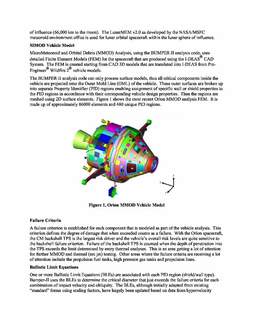
The BUMPER-II analysis code can only process surface models, thus all critical components inside thevehicle are projected onto the Outer Mold Line (OML) of the vehicle. These outer surfaces are broken upinto separate Property Identifier (PID) regions enabling assignment of specific wall or shield properties tothe PID regions in accordance with their corresponding vehicle design properties. Then the regions aremeshed using 2D surface elements. Figure 1 shows the most recent Orion MMOD analysis FEM. It ismade up of approximately 86000 elements and 480 unique PID regions.
Figure 1, Orion MMOD Vehicle Model
Failure Criteria
A failure criterion is established for each component that is modeled as part of the vehicle analysis. Thiscriterion defines the degree of damage that when exceeded counts as a failure. With the Orion spacecraft,the CM backshell TPS is the largest risk driver and the vehicle’s overall risk levels are quite sensitive tothe backshell failure criterion. Failure of the backshell TPS is counted when the depth of penetration intothe TPS exceeds the limit determined by entry thermal analyses. This is an area getting a lot of attentionfor further MMOD and thermal (arc jet) testing. Other areas where the failure criteria are receiving a lotof attention include the propulsion fuel tanks, high pressure gas tanks and propulsion lines.
Ballistic Limit Equations
One or more Ballistic Limit Equations (BLEs) are associated with each PID region (shield/wall type).Bumper-II uses the BLEs to determine the critical diameter that just exceeds the failure criteria for eachcombination of impact velocity and obliquity. The BLEs, although initially adapted from existing“standard” forms using scaling factors, have largely been updated based on data from hypervelocity
impact testing performed by NASA and/or Lockheed Martin. Hydrocode modeling using Autodyn® andCTH®
is used to fine tune test plans and to supplement test results. Representative key BLEs will beprovided.
Orion Design/Assessment Approach
Feedback is provided to the Orion design organization based on scrutiny of assessment results. By-PIDresults are sorted by number of failures and failures/exposed area so that it can be determined whereadditional protection is required and where protection mass can be reduced. Design parametersensitivities are performed to assess variations enabling evolution to a superior spacecraft configuration.
Orion MMOD Protection
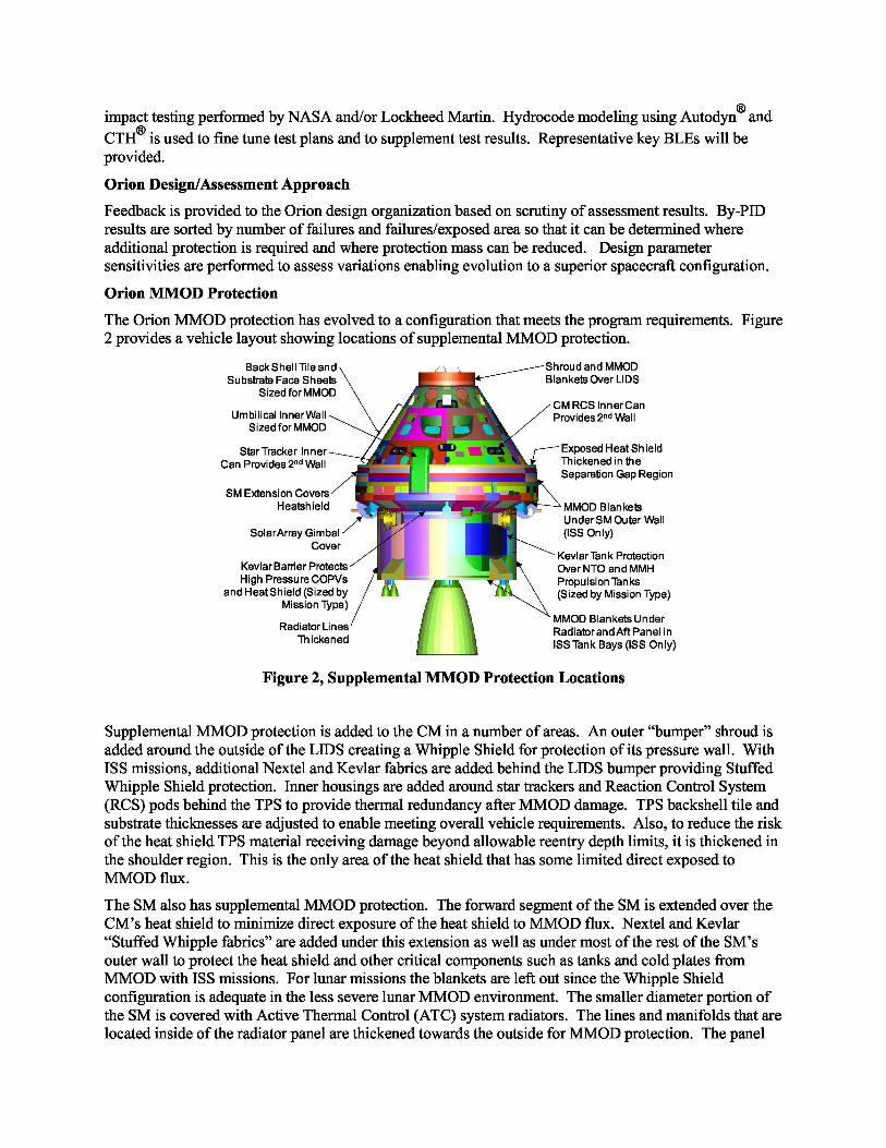
The Orion MMOD protection has evolved to a configuration that meets the program requirements. Figure2 provides a vehicle layout showing locations of supplemental MMOD protection.
Back Shell Tile andSubstrate Face Sheets •? i^
Sized for MMOD
Umbilical Inner WallSized for MMOD
C
Star Tracker InnerCan Provides 2nd Wall __ I ^,•
SM Extension Covers ••-^,,, s., ° qHeatshield
SolarArray Gimbal ^, f ••Cover
4Kevlar Barrier ProtectsHigh Pressure COPVs Nhl' "'N
and Heat Shield (Sized byMission Type)
Radiator LinesThickened
Shroud and MMODBlankets Over LIDS
CM RCS Inner CanProvides 2nd Wall
Exposed Heat ShieldThickened in theSeparation Gap Region
MMOD BlanketsUnder SM Outer Wall(ISS Only)
Kevlar Tank ProtectionOver NTO and MMHPropulsion Tanks(Sized by Mission Type)
MMOD Blankets UnderRadiator and Aft Panel inISS Tank Bays (ISS Only)
Figure 2, Supplemental MMOD Protection Locations
Supplemental MMOD protection is added to the CM in a number of areas. An outer “bumper” shroud isadded around the outside of the LIDS creating a Whipple Shield for protection of its pressure wall. WithISS missions, additional Nextel and Kevlar fabrics are added behind the LIDS bumper providing StuffedWhipple Shield protection. Inner housings are added around star trackers and Reaction Control System(RCS) pods behind the TPS to provide thermal redundancy after MMOD damage. TPS backshell tile andsubstrate thicknesses are adjusted to enable meeting overall vehicle requirements. Also, to reduce the riskof the heat shield TPS material receiving damage beyond allowable reentry depth limits, it is thickened inthe shoulder region. This is the only area of the heat shield that has some limited direct exposed toMMOD flux.
The SM also has supplemental MMOD protection. The forward segment of the SM is extended over theCM’s heat shield to minimize direct exposure of the heat shield to MMOD flux. Nextel and Kevlar“Stuffed Whipple fabrics” are added under this extension as well as under most of the rest of the SM’souter wall to protect the heat shield and other critical components such as tanks and cold plates fromMMOD with ISS missions. For lunar missions the blankets are left out since the Whipple Shieldconfiguration is adequate in the less severe lunar MMOD environment. The smaller diameter portion ofthe SM is covered with Active Thermal Control (ATC) system radiators. The lines and manifolds that arelocated inside of the radiator panel are thickened towards the outside for MMOD protection. The panel

itself helps to protect the radiator lines and manifolds as well as functioning as the “bumper” shield forthe main propulsion tanks and various other critical items located within that region of the SM. There is aKevlar wall protecting components within the forward portion of the SM that have credible shot lines fordamage from MMOD angling forward through the radiator panels. There is Whipple shield protectionadded to the various utilities running within the umbilical and to critical solar array actuators. Also, dueto the criticality of protecting the large propulsion fuel tanks there is specialized Kevlar blanket and foamshielding that is used to directly protect critical surfaces from damage from shot lines through theradiators and the SM’s aft closeout panel.