orion spacecraft mmod protection design and assessment
TRANSCRIPT
Orion Spacecraft MMOD Protection Design and Assessment
W. Bohla, J. Millera, K. Deightonb, J. Yasenskyb, C. Foremanb ,E. Christiansenc, J. Hydec , H. Nahrad
aLockheed Martin, Space Systems Co., P.O. Box 179, Denver, Colorado, 80201, USAbLockheed Martin Exploration & Science, 2625 Bay Area Blvd, Mail Code A7A, Houston, Texas, 77058, USA
cNASA Johnson Space Center, 2101 NASA Parkway, Mail Code SX2, Houston, Texas, 77058, USAdNASA Glenn Research Center, 21000 Brookpark Rd., Cleveland, Ohio, 44135, USA
Received Date Line (to be inserted by Production) (8 pt)
Abstract
The Orion spacecraft will replace the Space Shuttle Orbiter for American and international partner access tothe International Space Station by 2015 and, afterwards, for access to the moon for initial sorties and later forextended outpost visits as part of the Constellation Exploration Initiative. This work describes some of the effortsbeing undertaken to ensure that the Constellation Program, Orion Crew Exploration Vehicle design will meet orexceed the stringent micrometeoroid and orbital debris (MMOD) requirements set out by NASA when exposed tothe environments encountered with these missions. This paper will provide a brief overview of the approachesbeing used to provide MMOD protection to the Orion vehicle and to assess the spacecraft for compliance to theConstellation Program’s MMOD requirements.
Keywords: Orion, MMOD, Shielding Design, Constellation, HVIS.
1. I ntroduction
The Orion vehicle is being assessed for micrometeoroid and orbital debris (MMOD) risk for 210day missions to the International Space Station (ISS), short duration missions to the moon (LunarSortie) and long duration (210 day) missions to the moon (Lunar Outpost) to ensure compliance withthe Constellation Program’s MMOD requirements. The assessed vehicle consists of a Crew Module(CM) and a Service Module (SM) in a configuration that is similar to the architecture of the Apollospacecraft. The SM provides propulsion capabilities as well as other support utilities such as, water,compressed gases, active thermal control and power to the CM. The CM houses the crew and providesthe thermal protection system (TPS) that is necessary for Earth entry. The CM separates from the SMprior to Earth re-entry and lands using parachutes.
NASA’s Bumper-II software and the latest micrometeoroid and orbital debris environments arebeing used to assess the Orion vehicle for MMOD risk with the three mission types. The assessed risklevels are then checked against the requirements to ensure compliance. Lockheed Martin developed preand post processing macros and spreadsheets are used to streamline and reduce the chance for humanerror with Bumper-II data input and output. A detailed Orion vehicle analysis finite element surfacemodel is produced directly from the Orion computer aided design (CAD) model and is effectively“flown” thru the MMOD environments using the Bumper-II assessment software.
Nomenclature
BH w Brinell Hardness of Rear Wall (BHN)BH AL Brinell Hardness of Aluminum (BHN)c s,w Sound Speed of Rear Wall (km/s)c s,AL Sound Speed of Aluminum (km/s)
Pb Density of Bumper (g/cm2)Pw Density of Rear Wall (g/cm2)PAL Density of Aluminum (g/cm2)6w Yield Strength of Rear Wall (ksi)6AL Yield Strength of Aluminum (ksi)tbBumper Thickness (cm)tw Rear Wall Thickness (cm)tb.eq Bumper Equivalent Thickness (cm)tw,eq Rear Equivalent Wall Thickness (cm)
2. Orion MMOD Risk Analysis Tools
2.1 Bumper-II Assessment Software
NASA’s standard MMOD assessment software, BUMPER-II, is used to assess the Orion spacecraftfor MMOD loss of crew (LOC) and loss of mission (LOM) risk levels. BUMPER-II has a long trackrecord of use on various NASA manned programs, such as on mission analysis for the Space Shuttleand ISS. NASA’s latest anisotropic meteoroid and orbital debris environments are used with theBUMPER-II software to assess the micrometeoroid and orbital debris impact damage that exceedsfailure criteria limits. Input and output data are pre- and post-processed using EXCEL spreadsheets andmacros. Bumper-II software refinements have been made in order to reduce assessment times, eliminateunnecessary calculations and incorporate new and refined ballistic limit equations (BLEs). With respectto assessment time refinements, the processing time for the complete set of runs making up an ISSmission assessment has recently been reduced from over 13 hours to approximately 6.5 hours eventhough the number of separate runs increased from 36 to 48. Further modifications have been made toBUMPER-II by NASA to enable use of the new Meteoroid Engineering Model (MEM) input fileswhich are discussed in Section 3. All modifications to BUMPER-II are reviewed and approved throughan Orion Bumper-II Change Control Board (CCB).
2.2 Pre-Processing Tools
In order to speed analysis run preparations while reducing the chance of input error, Excel macrosare used to create script files that contain the analysis response inputs for BUMPER-II. The propertiesfor each of the vehicle model’s property identifier (PID) regions are maintained in Excel spreadsheets.The Excel macros convert the data into the script file format that Bumper-II requires. This approachprovides the response file inputs in the required cryptic format needed by Bumper-II while enablingeasy review and report table generation using Excel worksheets. The Excel PID spreadsheets are also

configured to provide ease of property modifications as required for trade study and designoptimization sensitivity assessments.
Similarly, the shield script files are created using a script file creator that automatically establishesthe element ranges needed for results reporting based on the model’s PIDs. With the large number ofPIDs and elements associated with the Orion model this saves much labor and reduces the chance ofhuman error.
2.3 Post-Processing Tools
Enormous amounts of data are created and post-processed while assessing the Orion missions forMMOD risk and it is common to run hundreds of complete sets of mission runs for sensitivity studies.Therefore, automation is necessary for post-processing of the Bumper-II output data. And, as with pre-processing, automation reduces the chance of error. The output macro combines the output sum fileresults for 34 separate Bumper-II runs in assessing complete lunar missions. ISS missions require 48separate runs. Additionally, the output macro accounts for component and system redundancies inrolling up overall mission LOC and LOM risk.
3. MMOD Environments
Orion MMOD analyses use ORDEM2000 as the orbital debris environment generator andMEMCxP/LunarMEM as the meteoroid environment generator. The ORDEM2000 environment asimplemented by the NASA/JSC orbital debris program office is used for all low earth orbit (LEO)mission phases [1]. The MEMCxP v2.0 meteoroid environment for Earth orbital spacecraft asdeveloped by the NASA/MSFC Meteoroid Environment Office (MEO) is used for all meteoroidanalyses up to the lunar sphere of influence (66,000 km to the moon). The LunarMEM v2.0 asdeveloped by the NASA/MSFC MEO is used for lunar orbital spacecraft within the lunar sphere ofinfluence.
The MEM environments account for the directionality of the helion, anti-helion, and the north andsouth apex and toroidal micrometeoroid flux populations [2]. Additionally, based on radar data, theaverage of the velocity distribution is higher than that of the older SSP-30425 environment. Theaverage velocity increased from 19 km/s to approximately 24 km/s. With MEM, the micrometeoroiddensity is assumed to be 1.0 gm/cm 3 .
4. MMOD Vehicle Model
4.1 Orion Vehicle Model
Micrometeoroid and orbital debris analysis, using the BUMPER-II code, uses detailed finiteelement models (FEM) for the spacecraft that are produced using the I-DEAS ® CAD System. TheFEM is created starting from CAD 3D models that are translated into I-DEAS from Pro-Engineer®
Wildfire 3 ® vehicle models.The BUMPER-II analysis code can only process surface models, thus all critical components inside
the vehicle are projected onto the outer mold line (OML) of the vehicle. These outer surfaces are
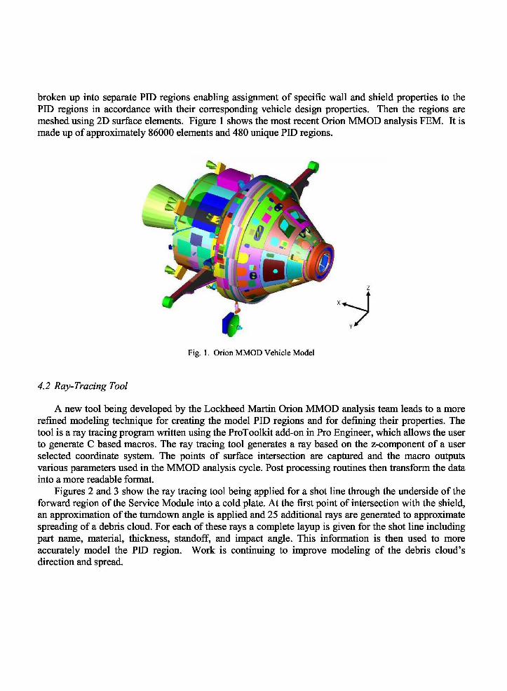
broken up into separate PID regions enabling assignment of specific wall and shield properties to thePID regions in accordance with their corresponding vehicle design properties. Then the regions aremeshed using 2D surface elements. Figure 1 shows the most recent Orion MMOD analysis FEM. It ismade up of approximately 86000 elements and 480 unique PID regions.
Fig. 1. Orion MMOD Vehicle Model
4.2 Ray-Tracing Tool
A new tool being developed by the Lockheed Martin Orion MMOD analysis team leads to a morerefined modeling technique for creating the model PID regions and for defining their properties. Thetool is a ray tracing program written using the ProToolkit add-on in Pro Engineer, which allows the userto generate C based macros. The ray tracing tool generates a ray based on the z-component of a userselected coordinate system. The points of surface intersection are captured and the macro outputsvarious parameters used in the MMOD analysis cycle. Post processing routines then transform the datainto a more readable format.
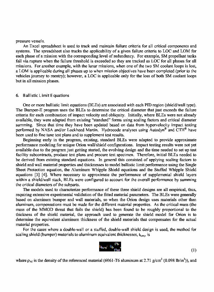
Figures 2 and 3 show the ray tracing tool being applied for a shot line through the underside of theforward region of the Service Module into a cold plate. At the first point of intersection with the shield,an approximation of the turndown angle is applied and 25 additional rays are generated to approximatespreading of a debris cloud. For each of these rays a complete layup is given for the shot line includingpart name, material, thickness, standoff, and impact angle. This information is then used to moreaccurately model the PID region. Work is continuing to improve modeling of the debris cloud’sdirection and spread.
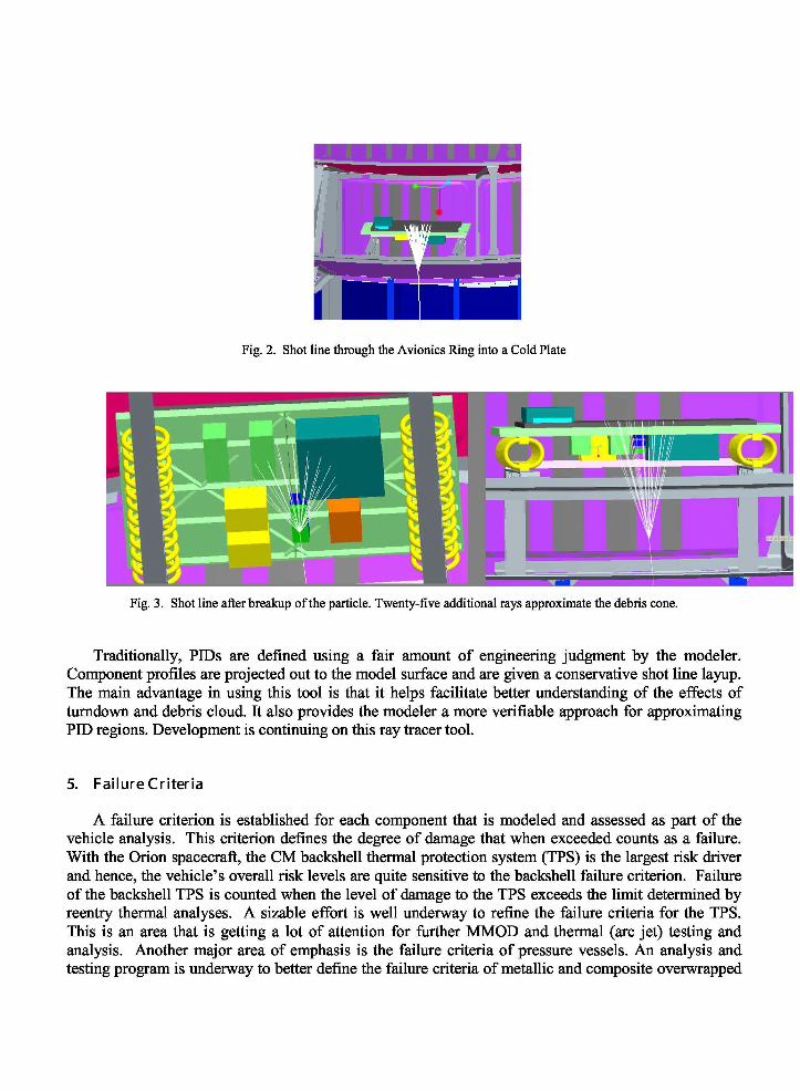
Fig. 2. Shot line through the Avionics Ring into a Cold Plate
Fig. 3. Shot line after breakup of the particle. Twenty-five additional rays approximate the debris cone.
Traditionally, PIDs are defined using a fair amount of engineering judgment by the modeler.Component profiles are projected out to the model surface and are given a conservative shot line layup.The main advantage in using this tool is that it helps facilitate better understanding of the effects ofturndown and debris cloud. It also provides the modeler a more verifiable approach for approximatingPID regions. Development is continuing on this ray tracer tool.
5. Failure Criteria
A failure criterion is established for each component that is modeled and assessed as part of thevehicle analysis. This criterion defines the degree of damage that when exceeded counts as a failure.With the Orion spacecraft, the CM backshell thermal protection system (TPS) is the largest risk driverand hence, the vehicle’s overall risk levels are quite sensitive to the backshell failure criterion. Failureof the backshell TPS is counted when the level of damage to the TPS exceeds the limit determined byreentry thermal analyses. A sizable effort is well underway to refine the failure criteria for the TPS.This is an area that is getting a lot of attention for further MMOD and thermal (arc jet) testing andanalysis. Another major area of emphasis is the failure criteria of pressure vessels. An analysis andtesting program is underway to better define the failure criteria of metallic and composite overwrapped
pressure vessels.An Excel spreadsheet is used to track and maintain failure criteria for all critical components and
systems. The spreadsheet also tracks the applicability of a given failure criteria to LOC and LOM foreach phase of a mission with the corresponding level of redundancy. For example, SM propellant tanksfail via rupture when the failure threshold is exceeded so they are tracked as LOC for all phases for allmissions. For another example, with the lunar missions, when one of the two SM coolant loops is lost,a LOM is applicable during all phases up to when mission objectives have been completed (prior to thevehicles journey to reentry); however, a LOC is applicable only for the loss of both SM coolant loopsbut in all mission phases.
6. Ballistic Limit Equations
One or more ballistic limit equations (BLEs) are associated with each PID region (shield/wall type).The Bumper-II program uses the BLEs to determine the critical diameter that just exceeds the failurecriteria for each combination of impact velocity and obliquity. Initially, where BLEs were not alreadyavailable, they were adapted from existing “standard” forms using scaling factors and critical diametersumming. Since that time they have been updated based on data from hypervelocity impact testingperformed by NASA and/or Lockheed Martin. Hydrocode analyses using Autodyn ® and CTH® havebeen used to fine tune test plans and to supplement test results.
Beginning early in the program, existing, standard BLEs were adapted to provide approximateperformance modeling for unique Orion wall/shield configurations. Impact testing results were not yetavailable due to the program just getting started, the evolving design and the time needed to set up testfacility subcontracts, produce test plans and procure test specimen. Therefore, initial BLEs needed tobe derived from existing standard equations. In general this consisted of applying scaling factors toshield and wall material properties and thicknesses to model ballistic limit performance using the SingleSheet Protection equation, the Aluminum Whipple Shield equations and the Stuffed Whipple Shieldequations [3] [4]. Where necessary to approximate the performance of supplemental shield layerswithin a shield/wall stack, BLEs were configured to account for the overall performance by summingthe critical diameters of the subparts.
The models used to characterize performance of these three shield designs are all empirical, thus,requiring extensive experimental validation of the fitted material parameters. The BLEs were generallybased on aluminum bumper and wall materials, so when the Orion design uses materials other thanaluminum, compensations must be made for the different material properties. As the critical mass (themass of the MMOD threat that fails the shield) has been found to be roughly proportional to thethickness of the shield material, the approach used to generate the shield model for Orion is todetermine the equivalent aluminum thickness of the shield materials that compensates for the actualmaterial properties.
For the cases where a double-wall or a stuffed, double-wall shield design is used, the method forscaling shield (bumper) materials to aluminum equivalent thicknesses, tb,eq, is
(1)
where ρAl is the density of the referenced material (6061-T6 aluminum at 2.71 g/cm 3 (0.098 lb/in3)), and
tb and Pb are the thickness and density of the actual Orion shield wall, respectively. It is also necessaryto scale the rear wall (critical component’s housing) as the rear walls are not generally constructed ofaluminum. The approach for scaling the thicknesses of metallic rear walls, tw,eq, is
(2)
where σAl is the yield strength of the reference material (6061-T6 aluminum at 35 ksi), and t w, ρw, andσw are the as designed thickness, density, and yield stress of the rear wall, respectively. In both of thesecases, the scaling equations are derived directly from the existing BLEs as incorporated in BUMPER-II.
The final regions where scaling relations are necessary are the regions of monolithic metal. Forthese regions the scaling determined from the monolithic BLE in BUMPER-II is
(3)
where BH and c s are the Brinell hardness and isentropic speed of sound, respectively.As hypervelocity impact testing enabled replacement of the approximation BLEs with BLEs
developed for the Orion wall/shield designs, it was found that generally the scaling approaches usedwith the standard BLEs were providing critical diameters that could be called rough at best. Thishighlights the need for early testing, increased use of hydrocode modeling, and perhaps, the need for astandard library of BLEs. In the case of Orion, the ballistic limit approximations that over performedtended to counter the ones that underperformed such that the overall vehicle results were not severelyfar removed from reality. And, the resulting error has generally been in the conservative direction dueto the tendency of the analyst to sway the approximation equations and input properties in thatdirection.
The Orion MMOD LOC and LOM assessments are now based on BLEs that have been developedor refined based on impact testing of the design configurations. Additional testing will provideadditional data points for further refinement of the Orion specific BLEs. Post critical design review(CDR) testing will ensure that the final flight hardware design BLEs are verified.
7. Orion MMOD Requirements
Loss of crew (LOC) MMOD Systems Requirement Document (SRD) requirements were definedfor each of the Orion mission types at the beginning of the Orion program. The requirements haveevolved somewhat but the LOC requirement is 1 in 800 for ISS missions, 1 in 1000 for lunar sortiemissions and 1 in 500 for lunar outpost missions. In addition, loss of mission (LOM) and LOC flowdown requirement allocations for overall vehicle LOC and LOM reliability were recently defined forthe lunar sortie and ISS missions. The MMOD LOC allocations are 1 in 2400 for lunar sortie and 1 in1200 for ISS missions. The LOM allocations are 1 in 1700 for lunar sortie and 1 in 160 for ISSmissions. Lunar outpost reliability LOC and LOM allocations have yet to be defined. The long delay inreceiving lunar sortie and ISS mission reliability allocations, and the continued lack of such allocations

for lunar outpost missions, proved the importance of having separately defined MMOD SRDrequirements for a program such as this.
8. Orion Design/Assessment Approach
Feedback is provided to the Orion design organization based on scrutiny of assessment results. By-PID results are sorted by number of failures and failures/exposed area so that it can be determinedwhere additional protection is required and where protection mass can be reduced. Many factorsinfluence the determination of the proper balance of MMOD risk across the modules and componentareas. The MMOD Team works closely with the spacecraft designers, mass properties, and otheranalysis disciplines to find this proper balance.
Additionally, the MMOD Team participates in and provides inputs on special trade studies that arecharged with determining the best design approach between various options that are underconsideration. Generally, the team assesses the impact of the various options on the MMOD risk levelsand provides feedback on each option’s impact on MMOD mass, cost and schedule. Varioussensitivities are also performed to assess design and operational variations enabling evolution to asuperior spacecraft configuration and mission approach.
9. I nnovation
A number of innovative design approaches have been used with the Orion vehicle in providingMMOD protection. An example is in the use of Kevlar fabrics and open cell foam to act as a rear wallor to supplemental rear wall protection for propellant tanks and other components on which they aredirectly mounted. The Kevlar and foam protection is utilized behind Whipple bumpers or StuffedWhipple bumpers and fabric layers. In some cases Kevlar layers act wholly as the rear wall in insuringthat no surface damage is sustained by the protected component and in other cases Kevlar layerssupplement the protection that is inherent in the component’s outer wall. In both cases, the Kevlarfabric layers are separated from the surface being protected or supplemented by a layer of open-cellpolyimide foam. Depending on the design intent, the Kevlar is used to either fully stop or greatly slowthe debris cloud constituents. Upon debris cloud impingement, the Kevlar stretches and deflects as thefoam layer locally compresses between the Kevlar and component wall. This design approach appearsto allow the Kevlar to build up membrane stresses in slowing or stopping penetration. The foamthickness and compressive strength is selected to limit surface damage to the component while allowingthe impact momentum to be reacted by the protected component. Development testing has shown theKevlar and foam design to be very effective in limiting damage to the component being protected.
Other innovative design solutions include the use of multi-functional materials such as MMOD rearwalls that also perform as redundant reentry thermal barriers, or structural members, and using anextension of the SM outer wall to protect the heat shield. Also, testing has shown that the use withOrion of composite structural layers instead of titanium within the TPS reduces the likelihood ofpenetration of the crew pressure wall located behind it.
Back Shell Tile andSubstrate Face Sheets
Sized for MMOD
Umbilical Inner WallSized for MMOD
Star Tracker InnerCan Provides 2nd Wall
SM Extension CoversHeatshield
SolarArray GimbalCover
Kevlar Barrier ProtectsHigh Pressure COPVs
and Heat Shield (Sized byMission Type)
Radiator LinesThickened
Shroud and MMODBlankets Over LIDS
CM RCS Inner CanProvides 2nd Wall
MMOD Blankets UnderRadiator and Aft Panel inISS Tank Bays (ISS Only)
Kevlar Tank ProtectionOver NTO and MMHPropulsion Tanks(Sized by Mission Type)
Exposed Heat ShieldThickened in theSeparation Gap Region
MMOD BlanketsUnder SM Outer Wall(ISS Only)
10. Orion MMOD Protection
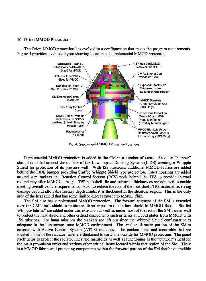
The Orion MMOD protection has evolved to a configuration that meets the program requirements.Figure 4 provides a vehicle layout showing locations of supplemental MMOD protection.
Fig. 4. Supplemental MMOD Protection Locations
Supplemental MMOD protection is added to the CM in a number of areas. An outer “bumper”shroud is added around the outside of the Low Impact Docking System (LIDS) creating a WhippleShield for protection of its pressure wall. With ISS missions, additional MMOD fabrics are addedbehind the LIDS bumper providing Stuffed Whipple Shield type protection. Inner housings are addedaround star trackers and Reaction Control System (RCS) pods behind the TPS to provide thermalredundancy after MMOD damage. TPS backshell tile and substrate thicknesses are adjusted to enablemeeting overall vehicle requirements. Also, to reduce the risk of the heat shield TPS material receivingdamage beyond allowable reentry depth limits, it is thickened in the shoulder region. This is the onlyarea of the heat shield that has some limited direct exposed to MMOD flux.
The SM also has supplemental MMOD protection. The forward segment of the SM is extendedover the CM’s heat shield to minimize direct exposure of the heat shield to MMOD flux. “StuffedWhipple fabrics” are added under this extension as well as under most of the rest of the SM’s outer wallto protect the heat shield and other critical components such as tanks and cold plates from MMOD withISS missions. For lunar missions the blankets are left out since the Whipple Shield configuration isadequate in the less severe lunar MMOD environment. The smaller diameter portion of the SM iscovered with Active Control System (ATCS) radiators. The coolant lines and manifolds that arelocated inside of the radiator panel are thickened towards the outside for MMOD protection. The panelitself helps to protect the radiator lines and manifolds as well as functioning as the “bumper” shield forthe main propulsion tanks and various other critical items located within that region of the SM. Thereis a MMOD fabric wall protecting components within the forward portion of the SM that have credible
shot lines for damage from MMOD angling forward through the radiator panels. There is Whippleshield protection added to the various utilities running within the umbilical and to critical solar arrayactuators. Also, due to the criticality of protecting the large propulsion fuel tanks there is specializedMMOD blankets and foam shielding that is used to directly protect critical surfaces from damage fromshot lines through the radiators and the SM’s aft closeout panel. The references in the text are missing.You may want to add them in the text. I think there is a need for a reference on ORDEM just like thereis reference on MEM.
R eferences
[1] Liou J-C, Matney M, Anz-Meador P, Kessler D, Jansen M, Theall J. The New Orbital Debris EngineeringModel ORDEM2000. NASA/TP-2002-210780. May 2002.
[2] McNamara H, Suggs R, Kauffman B, Jones J, Cooke W Smith, S.ing A. Meteoroid Engineering Model(MEM): A Meteoroid Model for the Inner Solar System. Earth, Moon, and Planets, 2004; 95: 123-139.
[3] Christiansen EL. Design and Performance Equations for Advanced Meteoroid and Debris Shields. Int. J.Impact Engng., 1993; Vol 14: 145-156.
[4] Christiansen EL, Crews JL. Enhanced Meteoroid and Orbital Debris Shielding. Int. J. Impact Engng., 1995;Vol 17: 217-228.
Orion Spacecraft MMOD ProtectionDesign and Assessment
Hypervelocity Impact SymposiumApril 2010
William E. BohlSenior Staff EngineerLockheed Martin SSCDenver, Colorado
0000 3/4/2010 1
Contributing authors
• Joshua E. Miller – LM Space Systems Co., Denver, CO
• Kevin D. Deighton – LM Exploration & Sciences Co., Houston, TX
• John A. Yasensky – LM Exploration & Sciences Co., Houston, TX
• Cory D. Foreman – LM Exploration & Sciences Co., Houston, TX
• Eric Christiansen – NASA Johnson Space Center, Houston, TX
• James Hyde – NASA Johnson Space Center, Houston, TX
• Henry Nahra – NASA Glenn Research Center, Cleveland, OH
2
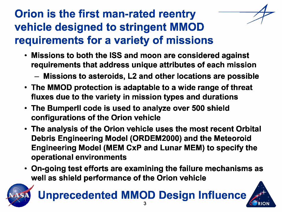
Orion is the first man-rated reentryvehicle designed to stringent MMODrequirements for a variety of missions
• Missions to both the ISS and moon are considered againstrequirements that address unique attributes of each mission– Missions to asteroids, L2 and other locations are possible
• The MMOD protection is adaptable to a wide range of threatfluxes due to the variety in mission types and durations
• The BumperII code is used to analyze over 500 shieldconfigurations of the Orion vehicle
• The analysis of the Orion vehicle uses the most recent OrbitalDebris Engineering Model (ORDEM2000) and the MeteoroidEngineering Model (MEM CxP and Lunar MEM) to specify theoperational environments
• On-going test efforts are examining the failure mechanisms aswell as shield performance of the Orion vehicle
Unprecedented MMOD Design Influence3 AL
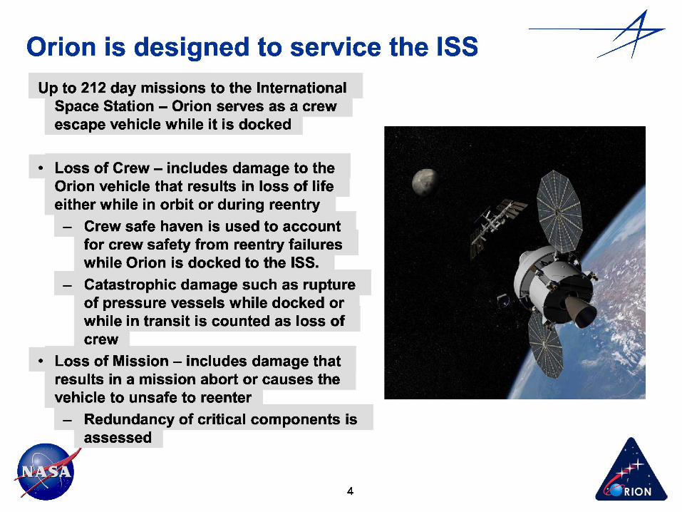
Orion is designed to service the ISSUp to 212 day missions to the International
Space Station – Orion serves as a crewescape vehicle while it is docked
• Loss of Crew – includes damage to theOrion vehicle that results in loss of lifeeither while in orbit or during reentry– Crew safe haven is used to account
for crew safety from reentry failureswhile Orion is docked to the ISS.
– Catastrophic damage such as ruptureof pressure vessels while docked or .while in transit is counted as loss ofcrew
• Loss of Mission – includes damage thatresults in a mission abort or causes thevehicle to unsafe to reenter– Redundancy of critical components is
assessed
4

Orion is designed to perform up to 225 daylunar missions
Sortie missions provide 7 days in low .lunar orbit and up to an additional 15days in transit .
Outpost missions provide up to 210 daysin low lunar orbit and up to anadditional 15 days in transit
• Loss of Crew – includes damage to theOrion vehicle that results in loss of lifeeither while in space or during reentry– All vehicle damage that results in
loss of life is counted• Loss of Mission – includes damage that
results in a shortened mission or . .prevents meeting science/missionobjectives– Redundancy of critical components
is assessed
5

Stringent loss of crew and loss of missionMMOD requirements have been defined
Maximum Allowable MMOD Risk Level for Each Mission Type
LOC = 1 in 1200
LOC =1 in 2400 LOC = 1 in 500
LOM = 1 in 160
LOM = 1 in 1700

SystemLossofCrew
PNCL LOC Risk 1-in-XCM Backshell (AETB8) 0.99960946 0.00039054 2,561SM Propellant Tanks 0.99997665 0.00002335 42,827LIDS 0.99998500 0.00001500 66,667SM HP COPY Tanks 0.99998983 0.00001017 98,284Umbilical 0.99999636 0.00000364 274,618CM COCking Hatch (AFRSI) 0.99999682 0.00000318 314,021SM Mncs/ECLSS 0.99999732 0.00000268 372,544CM Other Thermal Barriers 0.99999764 0.00000236 423,105CM Windows 0.99999767 0.00000233 429,014Heatshield 0.99999836 0.00000164 609,417
0-1 1-2 2-3 3-4 4-5 5-6 6-^
cityBin(km/s)
10-11 11-12 1213 13-1414-15 15-1616-17
BumperII combines model inputs withenvironments to determine risks
Spacecraft Configuration (I-DEAS)
I-DEAS Finite Element Model
• Describes spatial relationships of spacecraft components• Defines spacecraft orientation (velocity and zenith directions• Defines MM/OD shield regions
Meteoroid & Debris Environments (GEOMETRY)• Threat directions• Velocity distribution „^• Shadowing iT;• f
Critical Particle Diameter Calculation (RESPONSE)• Protection capability
7
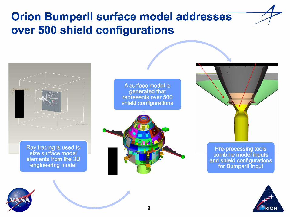
Orion BumperII surface model addressesover 500 shield configurations
8

ORDEM/MEM environments are combinedwith Orion attitudes and trajectories
9
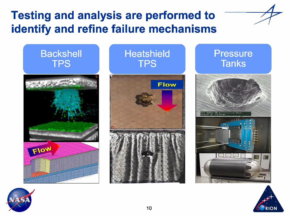
Testing and analysis are performed toidentify and refine failure mechanisms
10
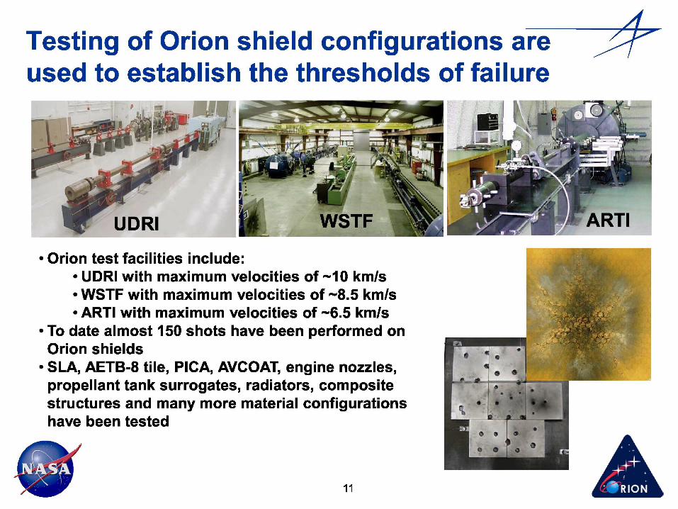
• Orion test facilities include:• UDRI with maximum velocities of ~10 km/s• WSTF with maximum velocities of ~8.5 km/s• ARTI with maximum velocities of ~6.5 km/s
• To date almost 150 shots have been performed onOrion shields
• SLA, AETB-8 tile, PICA, AVCOAT, engine nozzles,propellant tank surrogates, radiators, compositestructures and many more material configurationshave been tested
Testing of Orion shield configurations areused to establish the thresholds of failure
11
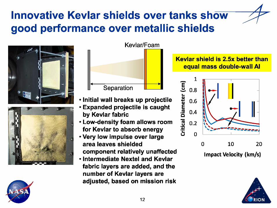
Innovative Kevlar shields over tanks showgood performance over metallic shields
Kevlar/Foam
Kevlar shield is 2.5x better thanequal mass double-wall Al
• Initial wall breaks up projectile• Expanded projectile is caught
by Kevlar fabric• Low-density foam allows roomfor Kevlar to absorb energy
• Very low impulse over largearea leaves shieldedcomponent relatively unaffected
• Intermediate Nextel and Kevlarfabric layers are added, and thenumber of Kevlar layers areadjusted, based on mission risk
1
0.8 .-►L
0.6M
0 0.4 ••n
0.2 %
v 0
0 10 20
Impact Velocity (km/s)
12

Through design and advanced shieldsOrion meets safety requirements
Advise Back Shell Tile and Shroud and MMOD
Design Model Substrate F ace SheetsSized for MMOD
Blankets Over LIDS
-Engineers Update f` CM RCS Inner CanProvides 2nd Wall
Exposed Heat Shield r;
-',Thickened in the Star Tracker Inner
Separation Gap Region e, Can Provides 2nd Wall
9 Umbilical Inner Wall
SM Extension Sized for MMOD
Covers Heatshield MMOD BlanketsUnder SM Outer
Kevlar Barrier Protects Wall (ISS Only)Shield Failure High Pressure COPVs
Adjustmentsand Heat Shield (Sized
Criteria by Mission Type) _` ''
Kevlar/Foam ProtectionOver Propulsion Linesand NTO and MMH Tanks
Solar Array Gimbal (Sized by Mission Type)Cover ^^ -
Radiator Lines MMOD Blankets Under
Thickened Radiator and Aft Panel in
Vehicle ISS Tank Bays (ISS Only)
Analysis
ISS 1208 160
Lunar Sortie 2822 1685
Lunar Outpost 536 25913 = ..
Orion will provide safe crew access toLEO and will support a flexible path formanned exploration beyond
• Orion MMOD design is robust and will meet stringentrequirements for crew safety and mission success
• Orion MMOD protection is tailored for the mission type– Meets protection requirements for high MMOD risk
missions while keeping vehicle mass on low MMOD riskmissions in line with the level of risk
• Institutes late TPS inspection with the higher risk ISSmissions to improve crew safety while minimizing thevehicle mass
• Forward work is planned to continue impact testing andvehicle analysis to optimize and verify Orion MMODprotection
Unprecedented MMOD Design Influence14 •