abstract - slac.stanford.edu · allow system manager to take advantage of already ... leitz...
TRANSCRIPT
SLAC-PUB-5625 August 1991 0
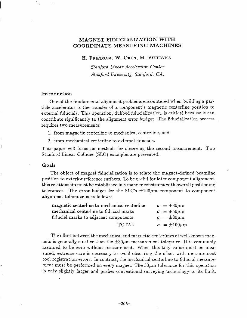
THE NEW COORDINATE MEASUREMENT MACHINE *
- A SOPHISTICATED TOOL FOR QUALITY CONTROL AND SURVEY AND ALIGNMENT -
Bemd T. Wand Stanford Linear Accelerator Center
Stanford University Stanford,CA 94309
ABSTRACT The most significant development in the manufacturing area over the last twenty years has been the Numerical Control (NC) machine tool. NC machines have greatly increased machining throughput, minimized operator error, and provided uniform quality parts. What these machines are to manufacturing, Coordinate Measuring Machines (CMM) are to inspection for many of the same reasons. The CMM is a physical representation of a three-dimensional rectangular coordinate system. It is comprised of moving parts which travel along three straight, orthogonal paths, carrying a probe that is used to address a work piece which is fixed in the established coordinate system. Linear encoders on each of the axes determine the displacement of the probe. In February of 1990 the Stanford Linear Accelerator (SLAC) purchased a LEI’IZ PM 12106 CMM. The Quality Control (QC) team and the Survey and Alignment Team (SAT) share the machine. Tbe responsibility for the machine lies with the Survey and Alignment group.
* Work supported by the Department of Energy Contract, DE-AC03-76SF00515

Page 2
1.0 Introduction . . . . . . . . . . . . . . . . . . . . . . . . . . . . . . . . . . . . . . . . . . . __UII...................................................................... 3 2.0 CMM system .overview . . . . . . . . . . . . . . . . . . . . . . ..-.--....-...................................................................... 3 2.1 Machine . . . . . . . . . . . . . . . . . . . . . . . . . . . . . . . . . . . . . . . . . . . . . . . ..-..-....-.-..................................................................... 3 2.2 Probes . . . . . . . . . . . . . . . . . . . . . . . . . . . . . . . . . . . . . . . . . . . . . . . . . . . . . . . . . . . . . . . . . . . . . . . . . . . . . . . . . . . . . . . . . . . . . . . . . . . . . . . . . . . . . . . . . . . . . . . . .................. 4 2.3 Operation of CMM . . . . . . . . . . . . . . . . . . . . . . . . . . . . . . . . . . . . . . . . . . . . . . . . . . . . . . . . ..*........................................*................. 4 2.4 Software and computer . . . . . . . . . . . . . . . . . . . . . . . . ..-................................................................................... 5 2.5 Future plans . . . . . . . . . . . . . . . . . . . . . . . . . . . . . . . . . . . . . . . . . . . . . ..-...........*.................................................................... 5 3.0 The Application of the CMM in Quality Assurance . . . . . . . . . . . . . . . . . . . . . . . . . . . . . . . . . . . . . . . . . . . . . . . . . . . . . . . . . . . . . . . . . . 6 4.0 The Application of the CMM in Survey and Alignment . . . . . . . . ..*................................................. 7 4.1 Fiducialization Technology . . . . . . . . . . . . . . . . . . . . . . . . . ..*............................................................................. 7 4.2 Project example: Positron target . . . . . . . . . . . . . . . . . . . . . . . . . . . . . . . . . . . . . . . . . . . . . . . . . . . . . . . . . . . . . . . . . . . . . . . . . . . . . . . . . . . . . . . . . . . . . . . . 8 4.2.1 Task description . . . . . . . . . . . . . . . . . . . . . . . . . . . . . . . . . . . . . . . . . . . . . . . . . . . . . . . . . . . . . . . . . . . . . . . . . . . . . . . . . . . . . . . . . . . . . . . . . . . . . . . . . . . . . . . . . . . . . . . 8 4.22 Shaft coordinate system . . . . . . . . . . . . . . . . . . . . . . . . . . . . . . . . . . . . . . . ..~.......~...................*............................~.......~ 8 4.2.3 Benefits . . . . . . . . . . . . . . . . . . . . . . . . . . . . . . . . . . . . . . . . . . . . . . . . . . . . . . . . . . . . . . . . . . . . . . . . . . . . . . . . . . . . . . . . . . . . . . . . . . . . . . . . . . . . . . . . . . . . . . . . ............. 8 Acronyms Appendix A: Illustrations Appendix B: CiMM technical data Appendix C: QC example Appendix D: Alignment example Appendix E: SLAC-PUB 375
LEITZ Coordinate Measuring Machine Page 3
1. Introduction
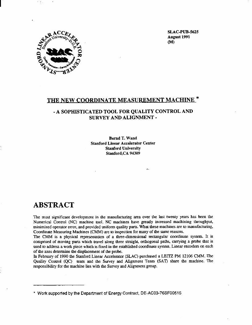
The most significant development in the manu- facturing area over the last twenty years has been the Numerical Control (NC) machine tool. NC machines have greatly increased machining throughput, minimized operator error, and pro- vided uniform quality parts. What these ma- chines are to manufacturing, Coordinate Mea- suring Machines (CMM) are to inspection for many of the same reasons. The CMM is a physical representation of a three-dimensional rectangular coordinate system. It is comprised of moving parts which travel along three straight, orthogonal paths, carrying a probe that is used to address a work piece which is fixed in the established coordinate system. Linear encoders on each of the axes determine the displacement of the probe. In February of 1990 the Stanford Linear Accel- erator (SLAC) purchased a LEITZ PM 12 106 CMM. The Quality Control (QC) team and the Survey and Alignment Team (SAT) share the machine. The responsibility for the machine lies with the Survey and Alignment group.
2. CMM system overview
2.1. Machine
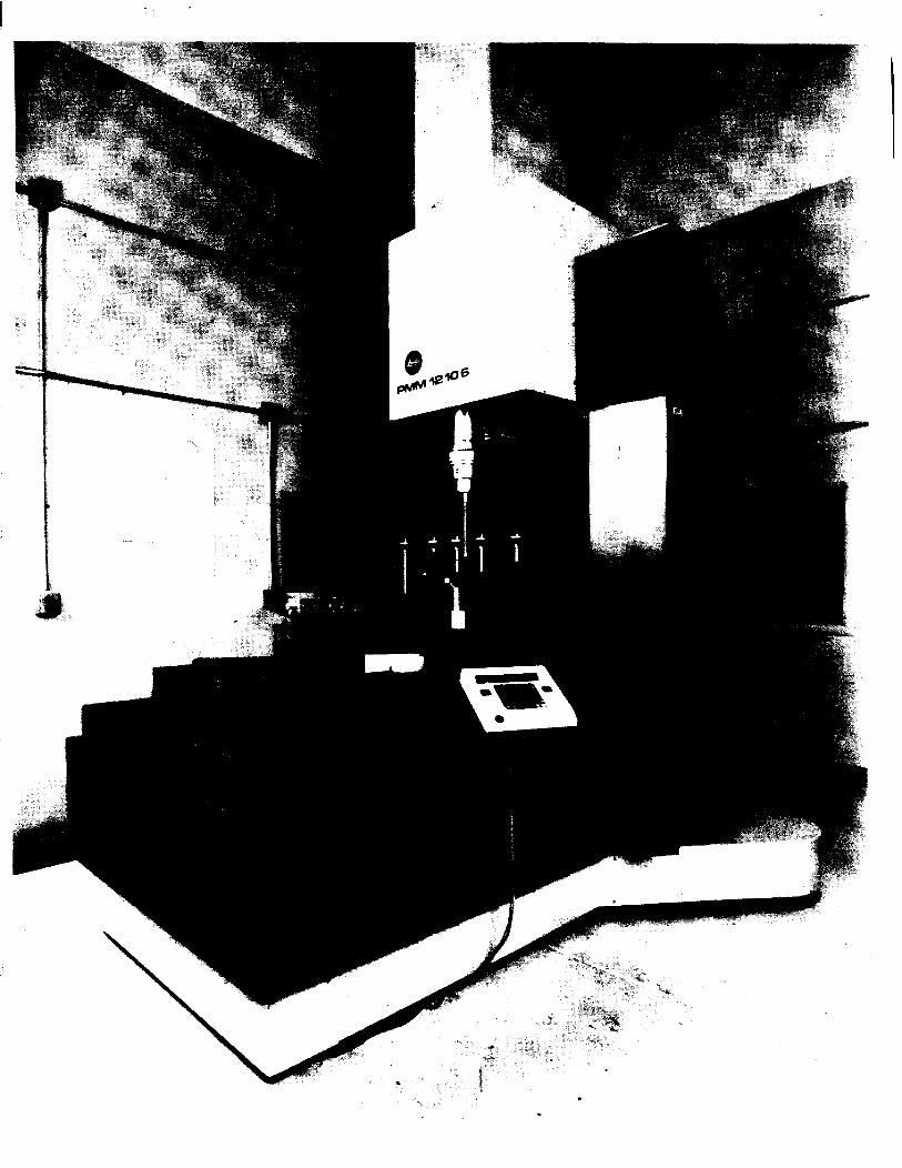
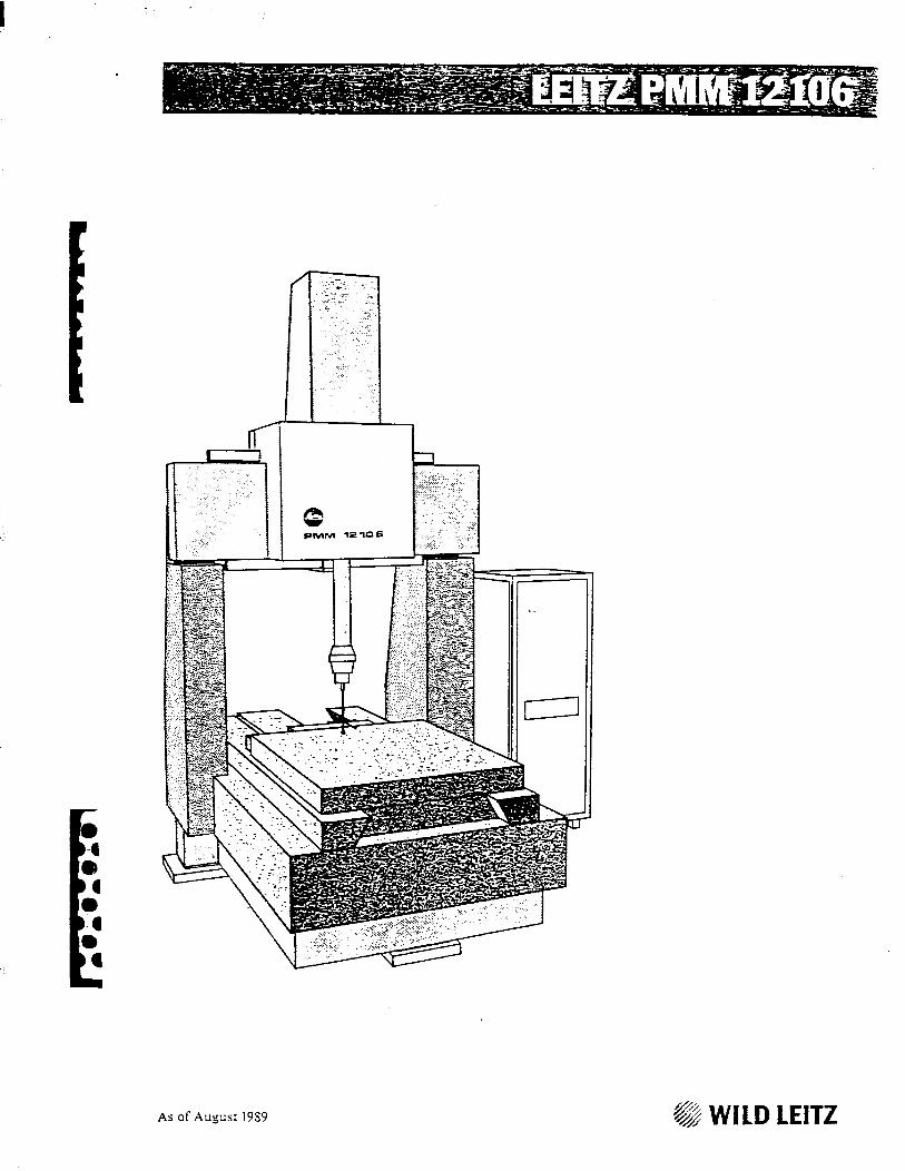
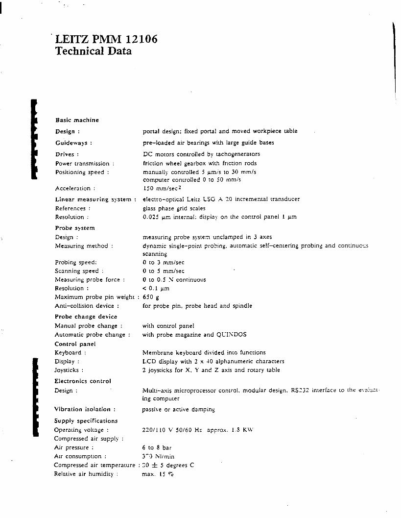
The complete technical data for the Leitz PM 12106 are added for more detailed reference in Appendix A. However, the most important facts of the machine are as follows:
- The Leitz PM 12106 is a fixed bridge design with a moving table.
- Measuring range: 1200 mm x 1000 mm x 600 mm. The part should be 10 % smaller than the maximum measuring range to allow room to access the sides and top of the part with normal probe clusters.
Fig. 1 CMM Leie PM12106
- Weight capacity: 2200 lbs. A load sensing mechanism checks the balance and slows the machine down if the load exceeds 1400 lbs.
- The cast iron supports and the drive mecha- nisms ride on air bearings to minimize vibra- tions.
- Each axis is equipped with a glass scale with 0.6 pm spaced grating. The diffraction pattern is interpolated to 0.025 pm.
- The smallest increment of measured value that can be displayed is 0.1 pm. (Resolution).
- The machine accuracies are measured in linear and volumetric terms. The linear accuracies refer to the absolute value of the difference between a calibrated length of a gauge block and the actual measured results obtained from the machine along each axis. However, it is volumetric accuracy that is important By positioning the above gauge block freely in space and utilizing the entire system of the measuring machine, the total measuring accuracy (volumetric accuracy) is determined. The volumetric accuracy is -0.8 pm + 2.5 ppm (parts per million) which amounts to a maximum error of 5 pm over the maximum measurement distance of 1.67 m.

LEIlZ Coordinate Measuring Machine Page 4
2.2. Probes
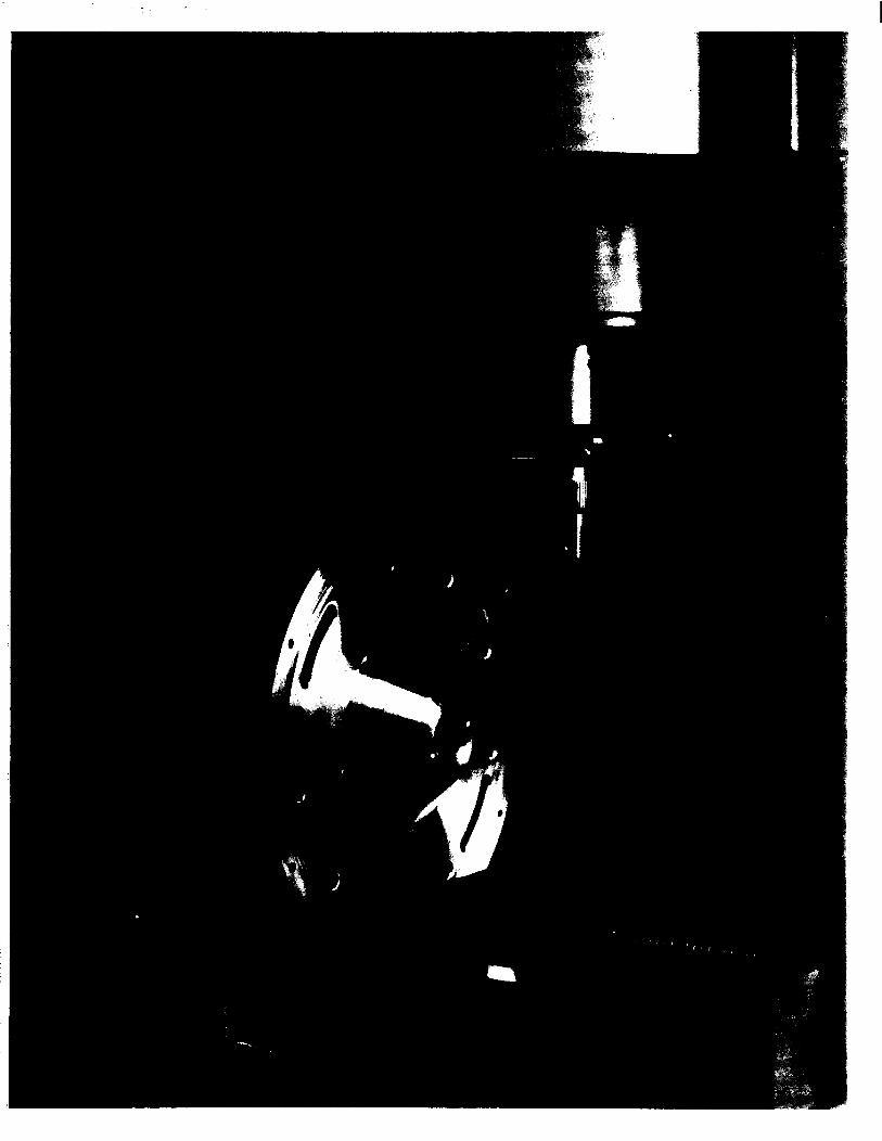
The probe head is a miniature 3-D measuring system by itself. The probe assembly of one or more probes mounted on the probe head is driven into the object by the operator or by a CNC program tmtil the force on the probe ex- ceeds a certain treshhold. The probe then backs away from the part until it reaches another threshhold at which it takes the measurement. It backs off in such a way that the force on the probe is normal to the surface. Data recorded for a measurement are the positions of the x, y, z scales and the deflection of the probe head in x, y, z. The probe pressure can be varied to make it possible to measure even soft copper parts with milligram pressure. It is possible to reach up to 400 mm inside parts e.g. to extract data on bores and other features which are gen- erally difficult to access.
Fig. 2 CMM meaning probe head
The calibration of the probes serves two pur- poses: 1.) It locates the center of each probe ball in reference to each other mounted probe, and
2.) a deflection matrix of the probe assembly is generated. This calibration is run for each probe by measuring- a ceramic sphere with a known diameter (25mm + O.ll.tm) in a fixed position. The probe tips are made of synthetic ruby. They are very bard and have a very high sphericity. The diameters in our selection range from 0.5 mm - 8 mm depending on the size of the work piece. The probe head allows for measurements to be taken in a single point or scannin g mode. In the scanning mode data are collected while the probe is in contact with the work piece and moves along it. Besides the mechanical probes the machine can also operated with an optical probe. This probe is targeted for 2-D applications with distinctly defined features. Features as small as 3 pm (pixel size divided by magnification) can be measured. The optical probe does not require physical contact with the work piece.
2.3. Operation of CMM
The machine can be run in three different modes: 1.) The “in promptu” mode is used for first part
inspections and quick jobs. In this mode, the machine is operated manually by joystick.
2.) The automatic mode is for repeated measurements. As the machine is guided manually through a complete measurement cycle it is teaching itself and remembers how to measure the part. All parts which are similar to the first one can then be measured automatically.
3.) If the nominal shape and dimension of a part are available a program can be generated be- forehand. The part can then be measured in automatic mode.
The most efficient means of measuring complex Parts manually and for “self teach” programming is the procedure known as Part Coordinate System.. (PCS) joysticking. In. this mode of operation the joysticks drive the machine along the axes of the current PCS instead of parallel to the axes of the Machine Coordinate System (MCS). This permits efficient probing in skewed, constricted spaces.
LEIlZ Coordinate Measuring Machine Page 5
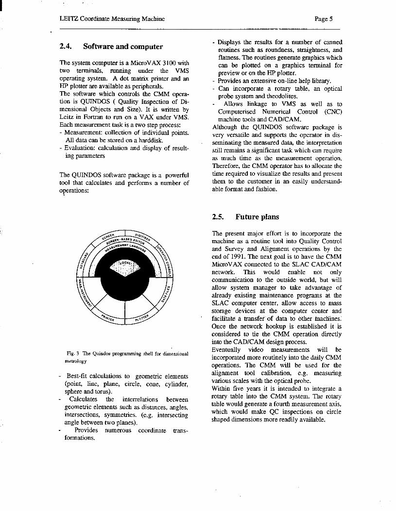
2.4. Software and computer
The system computer is a MicroVAX 3 100 with two terminals, running under the VMS operating system. A dot matrix printer and an HP plotter are available as peripherals. The software which controls the Ch4M opera- tion is QUINDOS ( Quality Inspection of Di- mensional Objects and Size). It is written by Leitz in Fortran to run on a VAX under Vh4S. Each measurement task is a two step process: - Measurement: collection of individual points.
All data can be stored on a harddisk. - Evaluation: calculation and display of result-
ing parameters
The QTJINDOS software package is a powerful tool that calculates and performs a number of operations:
Fig. 3 The Quindos programming shell for dimensional metrology
- Best-fit calculations to geometric elements (point, line, plane, circle, cone, cylinder, sphere and torus).
- Calculates the interrelations between geometric elements such as distances, angles, intersections, symmetries. (e.g. intersecting angle between two planes).
Provides numerous coordinate trans- formations.
- Displays the results for a number of canned routines such as roundness, straightness, and flatness. The routines generate graphics which can be plotted on a graphics terminal for preview or on the HP plotter.
- Provides an extensive on-line help library. - Can incorporate a rotary table, an optical
probe system and theodolites. - Allows linkage to VMS as well as to
Computer&d Numerical Control (CNC) machine tools and CAD/CAM.
Although the QUINDOS software package is very versatile and supports the operator in dis- seminating the measured data, the interpretation still remains a significant task which can require as much time as the measurement operation. Therefore, the CMM operator has to allocate the time required to visualize tbe results and present them to the customer in an easily understand- able format and fashion.
2.5. Future plans
The present major effort is to incorporate the machine as a routine tool into Quality Control and Survey and Alignment operations by the end of 1991. The next goal is to have the Ch4h4 MicroVAX connected to the SLAC CADKAh4 network. This would enable not only communication to the outside world, but will allow system manager to take advantage of already existing maintenance programs at the SLAC computer center, allow access to mass storage devices at the computer center and facilitate a transferof data to o’ther machines; Once the network hookup is established it is considered to tie the CMM operation directly into the CAD/CAM design process. Eventually video measurements will be incorporated more routinely into the daily CMM operations. The CMM will be used for the alignment tool calibration, e.g. measuring various scales with the optical probe. Within five years it is intended to integrate a rotary table into the CMM system. The rotary table would generate a fourth measurement axis, which would make QC inspections on circle shaped dimensions more readily available.

LEITZ Coordinate Measuring Machine
3. The Application of the CMM in Quality Assurance
The Leitz PM12106 CMM has many features that are especially useful for producing measurements of fabricated parts. Before obtaining the CMM many parts to be checked had features that were next to impossible to inspect. For example, parts that had internal formed surfaces often had to be sliced in half and measured using an optical comparator or microscope. Using this method it was at best a two dimensional picture of a three dimensional problem. In addition the part to be checked was destroyed by cutting it in half and the cutting process created a potential for distorting the part. To avoid cutting the part, methods of measurement were employed such as custom gages and setups using spherical bails to approximate the contour by measuring selected tangent points. An example of this is the measurement of the position of the form on the iris of an accelerator disc. The position of the toroidal surface is critical to the focus of the field structure in the cavity. The radius of the form is similarly critical to a level of approximately 10 pm. In the past to make this measurement the QC technician had to stack a selection of precision ball bearings in the iris. By measuring the height of the balls it was possible to derive the radius, pitch and point of tangency of the toroidal form. However, this method was not without its problems. The accuracy of the ball bearings and the gages used to measure their heights contribute to the accumulated error in the measurement, as does the parallelism and concentricity of the form. With the CMM it is possible to scan the form of the disc in sections and create a three dimensional model of the shape in the computer. Deviations in form can be represented either numerically or graphically to an accuracy of 2 pm or better. The accelerator disc example is representative of many of the Radio Frequency (RF) structures that are used at SLAC. Klystrons also have many complex shapes which form the RF field. Measuring these shapes non-destructively was often next to impossible to the level of accuracy required. With the CMh4 these measurements can now be obtained much easier and with a smaller margin of error.
deflection
40
4 0
moving into component moving away horn component
Fig. 4 Probing sequence
The CMM not only allows more direct and accurate measurements, it also reduces the measurement time in comparison to traditional QC procedures. Although initial measurements made on the CMM are often time consuming, repeated measurements can be made automatically, using the self-teach mode. The machine can also be trained to locate the new part and to adjust its reference planes to the orientation of the new part. This feature reduces the time it takes to make repeated measurements. Another feature of the CMM is an optical probe system that permits non-contact measurement of assemblies such as detector arrays. With the optical probe one can manually measure features of a part to a resolution of 3 pm (pixel size devided by magnification). One advantage of this system over the optical comparator is that the heat imparted to the part being checked is very low. Large copper arrays measured on the optical comparator have been observed to visibly expand on the order of several tenths of a millimeter on a meter from the heat generated by the tungsten arc lamp . These examples demonstrate how the CMM can accomplish measurements that were previously impossible or very time consuming. However, this does not imply that the CM!+ is the most suited tool for all inspection problems. Common measurements using traditional methods are still adequate in accuracy and speed for many applications. Included in this folder are two examples of typical plots in inspection jobs. The first plot illustrates how the machine can simplify
LEllZ Coordinate Measuring Machine Page 7
evaluation of a formed surface. The measured piece is compared to a nominal profile that is generated using the geometric description taken from the engineering drawing. Deviations in form are shown as small tick marks on either the inside or outside of the ideal profile. At a glance the part can be evaluated as to whether or not it falls within the tolerance window. Previously evaluating a part even with this simple form would have required sectioning the part and producing an accurate transparency to scale that would be mounted on the optical comparator. The inspector would then manually line the part up to the form and compare the silhouette of the part to the transparency. Any inaccuracy in the template would then be transferred to the measurement of every part.
The second example illustrates how the machine can gather statistics. In this case the CMM was monitoring the temperature of the room and the expansion of the probe which directly influences the accuracy of the measurement. The temperature at the time of the test can be included in the inspection document besides providing other statistical data such as the mean, maximum and minimum sizes of the mn, and the standard deviations. The software which drives the machine is “BASIC like” and very flexible. Although the machine has been at SLAC for over a year it is still in the infant stage. To integrate the CMM into routine QC operation will continue to require a certain amount of discipline and elbow grease. However, the potential to obtain measurements that have been previously impossible or prohibitively expensive warrant the effort- It is certain that future accelerator projects will produce pieces of even greater complexity and higher accuracy and a machine of this type will prove its merit.
4. The Application of the CM&I in Survey and Alignment
Before a component can be positioned on a beamline, the component’s magnetic centerline must be related to external fiducials. Since in most instances the magnetic centerline coincides within the required tolerance with the mechanical centerline, a magnetic fiducialization is forgone and only an optical fidulization is employed instead. This involves
the definition of a mechanical centerline and of its relationship to external fiducials. To perform the fiducialization, a magnet coordinate system has to be established by defining an origin and the three rotation angles of the magnet. The datum definition can be done by either optical tooling. techniques .or, with a CMM. As optical tooling measurements are very time consuming, not automated and prone to errors, it is desirable to use the CMM fiduciahzation method instead. The establishment of a magnet coordinate system based on the mechanical center and the transfer to external fiducials will be discussed and presented with a recent project.
4.1. Fiducialization Technology
The method chosen for fiducialization has to be quick and have reliable accuracy better than 50 pm. In general, three methods are available, each of which has its own limitations as well as its strengths. Optical tooling is a simple and well understood alignment methodology. It used to be and in maw instances still is the standard fiducialization technique. The equipment is fairly cheap and readily available. However, optical’ tooling doesn’t provide ‘any ‘statistical information or blunder checks. Assuming no blunders, and considering the limitations of the observer, instruments and targets one can expect a best possible accuracy of 75 pm + 20ppm. Theodolite measurement systems provide an optical alternative. Redundant measurements and least squares data processing render very accurate data along with statistical information on data reliability. The required hardware and software is available off-the-shelf, but is many times more expensive than the optical tooling equipment. However, a limiting factor for the system accuracy is the targeting process. The magnet features have to be targeted, which limits the system performance. Under good conditions, accuracies of 3Olun + Sppm can be achieved. CMMs are the third alternative. The magnet features can be measured directly with a probe by either probing individual points or scanning surfaces. The operator is not dependent on individual targets and can work with surfaces directly. The measurements can be run
LEITZ Coordinate Measuring Machine Page 8
automatically and are repeatable as well as documented with program listings, output listings or plots. They are fast and reliable and if used correctly we can achieve an accuracy of 0.8 pm + 2.5 ppm.
4.2. Project example: Positron target
4.2.1. Task description
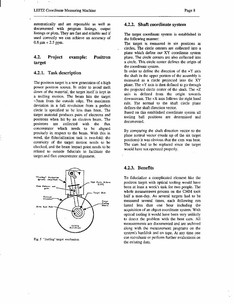
The positron target is a new generation of a high power positron source. In order to avoid melt down of the material, the target itself is kept in a trolling motion. The beam hits the target -3mm from the outside edge. The maximum deviation in a full revolution from a perfect circle is specified to be less than lmm. The target material produces pairs of electrons and positrons when hit by an electron beam. The positrons are collected with the flux concentrator which needs to be aligned precisely in respect to the beam. With this in mind, the fiducialization task is two-fold: the centricity of the target motion needs to be checked, and the beam impact point needs to be related to outside fiducials to facilitate the target and flux concentrator alignment.
Fig. 5 “Trolling” target mechanism
4.2.2. Shaft coordinate system
The target coordinate system is established in the following manner: The target is measured in six positions as circles, The circle .centers are collected into a plane which define our XY coordinate system plane. The circle centers are also collected into a circle. This circle center defines the origin of the coordinate system. In order to define the direction of the +Y axis the shaft in the upper portion of the assembly is measured as a circle projected into the XY plane. The +Y axis is then defined to go through the projected circle center of the shaft. The +Z axis is defined from the origin towards downstream. The +X axis follows the right hand rule. The normal to the shaft circle plane defines the shaft direction vector. Based on this established coordinate system all tooling ball positions are determined and documented.
By comparing the shaft direction vector to the plane normal vector (made up of the six target positions) it was obvious that the cam was bent. The cam had to be replaced since the target would have not operated properly.
4.2.3. Benefits
To fiducialire a complicated element like the positron target with optical tooling would have been at least a weeks task for two people. The whole measurement process on the CMM took half a man-day. As several targets had to be measured several times, each following mn lasted less than one hour including the acquisition of an object coordinate system. With optical tooling it would have been very unlikely to detect the problem with the bent cam. All measurements are documented and are archived along with the measurement programs on the system’s harddisk and on tape. At any time one can reevaluate or perform further evaluations on the existing dam
LEITZ Coordinate Measuring Machine Page 9
Acronyms
NC
CNC
SLAC
QC QA SAT
PPM
PCS
MCS
QUINDOS
VAX
VMS
CAD/CAM
RF
LEITZ
Numerical Control
Computerised Numerical Control
Coordinate Measuring Machine
Stanford Linear Accelerator
Quality Control
Quality Assurance
Stanford Alignment Team
Parts Per Million
Part Coordinate System
Machine Coordinate System
Quality Inspection of Dimensional Objects and Size
Digital Equipment Corporation computer type
VAX operating system
Computer Aided Design/ Computer Aided Manufacturing
Radio Frequency
CMM manufacturer (Division of Brown & Sharpe)

APPENDIX A: Illustrations

f
As of August 19S9 &s WILD LEITZ

APPENDIX B: CMM technical data
’ LEITZ PM&l 12106 Technical Data
Acceleration :
Linear measuring system References : Resolution :
portal design; fixed portal and moved workpiece table
pre-loaded air bearings with large guide bases
DC motors controlled by tachogenerators friction wheel gearbox with fncrion rods manually controlled 5 Fm:‘s to 30 mm/s computer controlled 0 co 50 mm/s 150 mm/set *
electro-optical Leirz LSG .A 20 incremental transducer glass phase grid scales 0.025 pm internal; dispiay on the comrol panel 1 pm
Probe system Design : IMeasuring method :
Probing speed: Scanning speed : tMeasuring probe force : Resolution : Maximum probe pin weight : Anti-collision device :
measuring probe system unclamped in 3 axes dynamic single-point probing, automatic self-centering probing and continuous scanning 0 to 3 mm/set 0 to 5 mm/set
for probe pin, probe head and spindle
0 to 0.5 N continuous < 0.1 pm 650 g
with control panel
Vibration isolation : passive or active damping
Supply specifications Operating voltage : Compressed air supply : Air pressure : 6 to 8 bar Air consumption : 3’3 Nlimin Compressed air temperature : ?O f 5 degrees C
Probe change device Manual probe change : Automatic probe change : Control panel Keyboard : Display : Joysticks :
Electronics control Design :
with probe magazine and QCINDOS
Membrane keyboard divided into functions LCD display with 2 x 40 alphanumeric characters 2 joysticks for X. k’ and Z axis and rotary table
Multi-axis microprocessor control, modular design, RS232 interface to the ovalual- ing computer
220/110 V 50/60 Hz apcrox. I.8 K\L
Basic machine
Design :
Guideways :
Drives : Power transmission : Positioning speed :
Relative air humidiry : max. IS 5
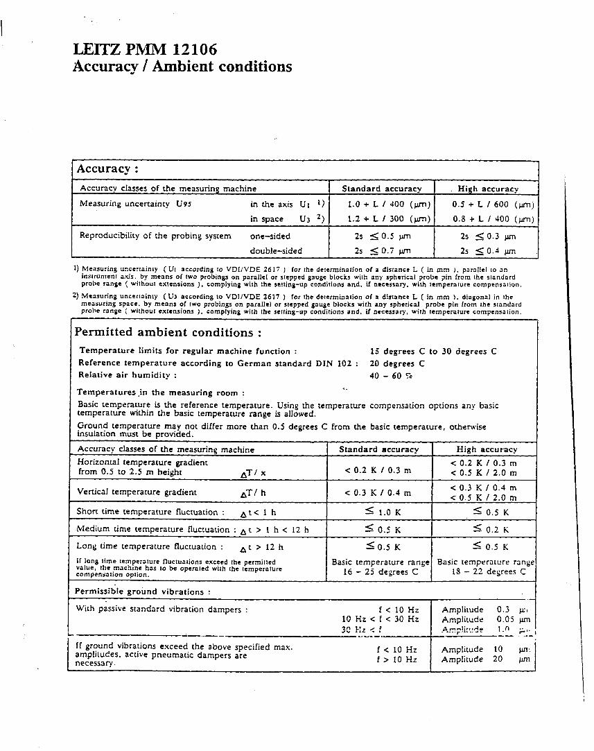
LEITZ PNIM 12106 Accuracv / Ambient conditions w
iccuracy : Accuracy classes of the measuring machine Standard accuracy High accuracy
Measuring uncertainty U95 in the axis U1 *> 1.0 + L / JO0 (Jim) 0.5 + L / 600 (Jun)
in u3 space 2) 1.2 + L / 300 (fl) 0.8 + L / 400 (fl)
Reproducibility of the probing system one-sided 2s so.5 pm 2s 5 0.3 pm
double-sided 2s 5 0.7 w 2s 5 0.4 pm
1) Measuring uncermimy ( UI according to VDI/VDE 2617 ) for rhe determination of a disrrnct L ( in mm 1. parallel to an instrumenr axis. by means of IWO probings on parallel or stepped gauge blocks with any spherical probe pin from the slondard probe range ( without extensions ). complying wilh the selling-up condilions and. if necessary, with Iemperalure compensalion.
2) Measuring uncertainty (U3 according to VDllVDE 2617 ) for lhe determinalion of a dislancc L ( in mm ). diagonal in the measuring space, by means of two probings on parallel or stepped gauge blocks with any spherical probe pin from the standard probe range ( without exlensions 1. complying wilh the setting-up conditions and, if necessary, with temperslure compensation.
Permitted ambient conditions : Temperature limits for regular machine function : 15 degrees C to 30 degrees C Reference temperature according to German standard DIN 102 : 20 degrees C Relative air humidity : 40 - 60 7-c
Temperatures,in the measuring room : 4.
Basic remperature is the reference temperature. Using the temperature compensation oprions any basic temperature within the basic temperature range is allowed. Ground temperature may not differ more than 0.5 degrees C from the basic temperacure, otherwise insulation must be provided.
Accuracy c!asses of the measuring machine Horizontal temperature gradienr from 0.5 to 2.5 m height ATi X
Vertical temperature gradient AT/ h
Standard accuracy
< 0.2 K / 0.3 m
< 0.3 K / 0.4 m
High accuracy < 0.2 K I 0.3 m < 0.5 K / 2.0 m
< 0.3 K / 0.4 m c 0.5 K / 2.0 m
Short time temperature fluctuation : At< 1 h
Medium time temperature Rucruation : A L > 1 h < 12 h
Long time tenperature fluctuation : At>l2h II long lime Iemperalure fluclualions exceed the permilred value, the machme has IO be operaled with the remperature compensation option.
Permissible ground vibrations :
5 1.0 K 5 0.5 K
5 0.5 K 5 0.2 K
SO.5 K d: 0.5 K
Basic temperature range Basic temperalure range 16 - 25 degrees C IS - 22 degrees C
.- With passive standard vibration dampers :
--..v_
f<lOHz Amplitude 0.3 JJZI 10 Hz < f c 30 Hz Amplirude 0.05 pm 32 Hz < f A rmmlir*nAe . .*..rs .-.4- t.0 4,.
me--- -- .-- If ground vibrations exceed the above specified max. amplitudes. active pneumatic dampers are necessary.
f < 10 Hz I
Amplitude 10 pn: f> 10 Hz Amplitude 20 v I
CEITZ F’iJ434 12106 Dimensions
h4easuring range (L x W x H) Permitted workpiece weight Table area (Length x Width) Portal size (Width x Height) Space under probe head; without probe pin Length of measuring machine Width with passive dampen Width with active dampers Height with passive dampers Height with active dampers
1200 x 1000 x 600 1000 (1400 Option) 1250 x 1050 1250 x 937 200 to 800 29-lo 1950 2385 34s: 3481
mm kg
mm mm mm mm mm mm mm
Weight of measuring machine 6300 Weight of e!ectronics cabinet 215
ks ks
Electronics cabinet 600 x 600 x 1750 mm
Width with active
Height
Width with passive dampers
@WILD LEITZ Wild Leitz GmbH D-6330 WeQiar
Optics. precision engineering, electronics Telephone (0 64 41) 29-O Telex 483 849 leiz d Telefax (0 6141) 29 33 99

APPENJXX C: OC exam&
L . i! a
I I-
--.---
i
t
OD d
Lo d

i
I
- 7
0 e
*
.v _- *.. 1.
00
a; t-l
I
+ ,
i
i
I
i i-
0 .
Ei
ul . . .

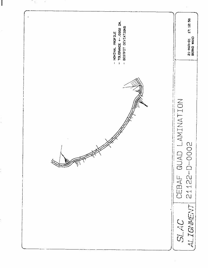
APPENDIX D: Alignment example
“E-’ . . .‘I-.- LL. T FLLFi i : j ‘-
t T-CI~(r~, CSY 7 T-CiR(2): CSY , T-CIR(3)y CS’Y , T-CX(4) t 25’: .* -I : 1-1, FiXI?, CS‘f

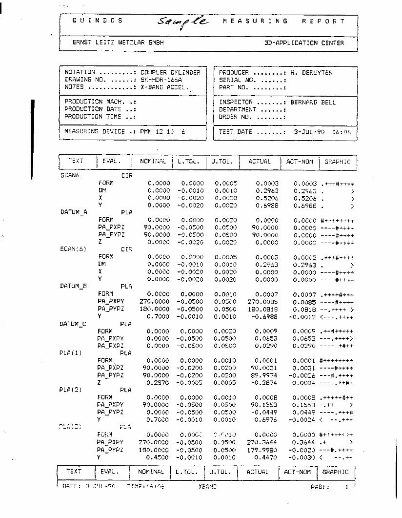
CUINDOS MEASURING REFORT
ERNST LEITZ WETZLAR GMSH 3D-APPLICATION CENTER
i MEASUEING DE:IICE .: FKK 12 1C 15 I
INSFECTOR ....... . BERNARD BELL DEFARTMENT ...... . I ORDER NO. ....... .
TEST DATE ....... . 3-JUL-90 lb:ijt, 1 I
1 TEXT I
1 EVfiL. 1 NCI?IIi’.!iiL ! i.TOL. f U.TOL. KTUAL 1 ACT-NOM I 1 I
GKGFHi#z , ,
I SCAN6
DATUM-A
ECGN i’ 6)
DATUM-B
DATUM-C
FLA(1)
PLA(2)
CI, m ,I. * Crl\r,
CiR FOKM DM X Y
FLA FORM PA-FXFZ PA-FYFZ z
CiX FrJk? DM X Y
PLA FOFiM PA-PXPY PFI-PYFi Y
PLA FORM Ph-FXFY PA-FXFZ
PLA FORM \ PA-PXPZ PAYPZ Z
PLA FORM PA-PXPY PA-PYPZ Y
-. A I- in FW? PCI-FXPY PA-PYFi Y
0.0990 0. OijCjtj 0. fjij#y o.mx~3 0.9CW -9.0019 0.0910 0.2963 0. 9990 -0. (3fj2fj 0.9920 -0 .52ql6 0. ooco -fj oijzrj . 0. 0929 0.6989
0 occo .
99 f)Q!>i) . .
90.0000 0 . O(jCi)
0. ocoo 0.0000 0.0010 0.0007 0.0997 . ++++#+++ 270.0090 -0.0590 0.0509 270.0085 0.0085 ----#ii++ 180. OOCO -0.0590 0. 0.599 180.0818 0.0818 --.++++ j
0.7000 -0.0010 0.0010 -0.6988 -0.9912 <---.++++
0.0900 0 cm0 . 0.9c90
o.ocoo 0. 0999 0.0010 0.0001 0,Oijij 1 #I++++++++ 90.0900 -0.0290 0.0299 9C.0031 0.003! ----#++++ 90.0000 -0 * 0200 0.0200 89.9974 -0.0026 ---#.++++
0.2570 -0.0995 0.0005 -0.2874 O.Oi]i)4 ----.++#+
0.0990 90.0900
o.o9c;o 0.7CCO
0. O&ij 0 , c~i:J~J.:. “70. or;99 i -9.0500 180 OCCO . -0.0599
0.43~0 -0.0010
0. OfjijCl
-0.0531)
-2 * o=ijfj
-C. Oi>zij
(! . O(jij(j -0.9919 -C.Of)2() -c .0920
0.0000 -0.0.509 -9. fjzijij
0. 0909 -0.0500 -0.03:Jo -0.0919
0, Ofj~ij 0. Qsijij 0.05d9 0 . 0929
0 m-l-vj . . m& 0.05i)f) 0. 0.599
0. ofjf:tfj 9ij. 0000 90.0099
0 . 0909
0. (jCjij2 . +++#+i++ 0.2963 . i 0 .-&se ‘776 . j 0.6988 . >
O.Oi)()f) #i++++i+i
0.9000 ----#+i++
0 * fjijfji) ----xi+++
0.0i:K~.: ----#++++
0. f)ijf)~ 0.2563 0.0909 0 .0990
0. C(1ij3 . +ii*++ii 0.2963 . > 0 . 0099 ----*ii++ 0.9990 ----#++++
0.0009 0.0653 0.0290
0. 0009 . ++##c++++ 0.0653 --- .++i+;. 0.0290 ---- i#++
0.0908 O.OrjO8 .++++i#++ 90 1553 . 0.1553 -.++ > -0.9449 0.0449 ---- .+i+$$
0.6976 -0.0024 c --.+++
0 . i)f;ijr:J 0. CdjClCl #+ ! +i+7 E-i 270.3b44 0.3644 .+ > 179.9980 -0 . Of-PfJ .& ---#. ++++
9.4479 -0. ijij3i.S ,< --.++
1
TEXT EVGL . [
NOM!N&L [ L.TOL. U.TOL. ACTUGL ACT-NOM GRAPHIC /
! TILTF: 7-J’IL -9P T1.y: . 1 L .,-.A . _d. J._ XEGb!F FAGE : 1 i
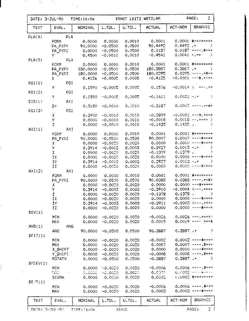
I DATE: 3-JUL-90 TIME:16:06 ERNST LEITZ WETZLAR PAGE: 2 L i
TEXT EVGL. NOMINAL L.TOL. I
U.TOL. ACTUAL ACT-NOM GRGFHIC
PLA(4) FLA FOfiM PA-FXFY Pa-?YFZ Y
FLA FCKM PA-PXFY PA-FXFZ X
PO1 Y
PO1 Y
GXI DY
FrJI X Y i
GXI Fi;FiM PA-FYPZ X Y Z IX I’( IZ
fix1 FORM FG FYPZ X- Y Z IX IY IZ
MIN MGX
GNG GNG
MIN MAX X-SHIFT Y-SHIFT FtOTGTN
1 MIN ,.-<. '"l,\ SIGMA
NIN NGX
0. fjfjfjtj -0 . i)!fbijij
-0. ~~5l)O
~0~0010
0. 0001 0, Ofjij 1 #++++++++ 90.4492 (2.4492 .+ j
0.018i t).c)19-; ----.#+++ -0.4541 i).otj41 -.++ .I;
0. OOOl 180.3887 180.0295
-0.4125
0.15i6
0. f)i)i)l #++++++++ 0.38E7 .+ > 0.02?5 ---- .i#++
-0.000 1 ---#.+i++
-f).i)i)1J .< ---.++
-0.1611 O,i)ij21 -.+ :>
-0.3137 rj.iji~l]7 ----.+i*+
-0.3999 -0 .ijtji) 1 ---#.++++
-0.0018 fj.f)ij!6 --.+-rti j
-0.1435 0.1435 . j
0.0001 90 .oooi
0.0000 0.3927
-0.1379 0.0000 0.3927 I). i)nij:j
0. Otjlj 1 #ii++++++ 0 . OW7 ----#t++i 0. !)fji)) m-e-#++++ 0.0013 -.+ > Cl.1379 * ‘:. 0. CjijQij -++++ rj.i)i:J13 - .+ > i).lj(jiji? ----g++++
0.0001 0. i)fjij 1 #iiiiiiii
90.0388 0.0383 ----.++#+ 0, iJf)f)ij 0.0000 ---#+++++
-0.3910 -0.0004 (---.++++ -0.1378 0.1378 . >
0.0000 0.0000 ----#++++ -0.3911 -0.0fj03 (---.++++
0.0000 ().OijijC) ----#ii++
-0 l O026
0.0019
90.3887
-0.0002 0.0007 0 , 0000
-0.0008 -0.3887
-0.0006 0.C j??
0. i);;t:lr
i).i)<j26 --- .++++j 0.0019 ---- +++g
0.3687 .+ >
0.0002 ----#++++ 0.0007 ----.#+++ 0. ooc:c~ ----#r+++ 0.0008 ----.#+++ 0.3687 .+ ?
O.@OOb ----.#+++ r,.?rjf)Z -.. --ii;.-7 I. (‘. I)002 #ii++++++
-0.00~:~6
0.0003 0.0006 ----,#+++ 0.0003 ----#++++
PLA(S) 0. f)f)fjil
-0 , 05ijij
-O.l)~ij~j
-0. i)ijij=
PO!(l)
PO1 (2)
DiS(1)
FOi(3j
0. 1590 -0 ()ij(j5 *
0.159ij -0. I):.$5
0 . 3 130
-0 i)l)i'j -. * -0.0010 -o.C)i)!ij
AXI 0 . 0000 O.Qi)i)ij
90.0000 -0. r)500
0 , o(:J()ij -I). (Ii:,:!:1
0.3914 -0. IyJfj~~~
0. OOCM -0. ijijzrj 0. fji)ijQ -o.Oi)Tij
0.3914 -0. i)ijl~~3
0.0000 -0. t)t.?ztj AXI (2)
0. oocm 90.0000
o.ooc~c~ 0.3914 0. oooi:, 0.0000 0.39!4 0.0000
DEV(1) -0. OO=‘!
-11. 0020
ANG (1)
BFI T(1) 90. OOO’! -O.cmJO
0.0000 0 . ocm 0.0000 0 . 0000 0 . f)ijl:li:l
-0.0020 -0. c>l:lZ’j -0.0020 -0 i)i)2lj . -0~~5oij
EFDEV(1
DE.'T;l)
TEXT EVGL. NOMINAL L.TOL. U.TOL. ACTUAL ACT-NOM GRGFHIC
f ! l-l&TF! 3-XJI -9s:' TTNF: : L!ci -XEKIT: F&GE: 2 I
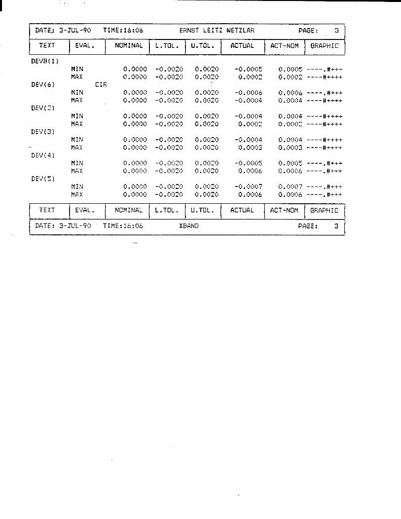
DATE,: 3-JUL-90 TIME:l6:06 EiiNST LEITZ WETZLAR PAGE: 3
TEXT EVAL . NGMINAL L.TOL. U.TOL. ACTUAL ACT-NOM GRAPH I C
DE’JE ( 1 1 MIN MAX
DEV161 NIN MAX
DEV(Z) MIN MAX
DEV(3) NIN
-. MAX DEV(4)
MIN MAX
DEV(Z) NIN MGX
0.0000 c , ‘Jl)~fj
CIR 0.0000 0.0000
-0. ijo
-I) . Ol)2iJ
-I). fjf:)~~ -0. tjO2ij
-I). oij2ij
-0. ijCi2i)
-0. I](:)04 0.O002
-0. cKJCJ4 0 .0003
0 .0005 ----.#+++ 0. Ot)Q2 ----#ii++
0. 0006 ----. #ii+ 0. ow4 ----#ii++
0. ooi:J4 ----#ii++ 0 . 0002 ----#iii+
0 . 0i:104 ----#++++ 0.0003 ----#ii++
0. ooi:J5 ---- .#+++
f).Oiji~6 ----.#i+i
0 fjfji)7 ---- . #iii .
0.f~ijf:lb -----#iii
TEXT EVAL. I
v NOM ANAL L.TOL. U.TOL. ACTUGL ACT-NOM !
GRAPHIC
DATE: 3-JUL-90 TXME:!6*06 . XEAND PAGE: 3 1
I I I

APPENDIX E: SLAC-PUB 375
MAGNET FIDUCIALIZATION WITH COORDINATE MEASURING MACHINES
H. FRIEDSAM, W. OREN,~~. PIETRYKX
Stanford Linear Accelerator Center
Stanford University, Stanford, CA.
Introduction
One of the fundamental alignment problems encountered when building a par- ticle accelerator is the transfer of a component’s magnetic centerline position to external fiducials. This operation, dubbed fiducialization, is critical because it can contribute significantly to the alignment error budget. The fiducialization process requires two measurements:
1. from magnetic centerline to mechanical centerline, and
2. from mechanical centerline to external fiducials.
This paper will focus on methods for observing the second measurement. Two Stanford Linear Collider (SLC) examples are presented.
Goals The object of magnet fiducialization is to relate the magnet-defined beamline
position to exterior reference surfaces. To be useful for later component alignment, this relationship must be established in a manner consistent with overall positioning tolerances. The error budget for the SLC’s f100pm component to component alignment tolerance is as follows:
magnetic centerline to mechanical centerline u = f30pm mechanical centerline to fiducial marks u = f50pm fiducial marks to adjacent components u = MOprn
TOTAL u = +lOOpm
The offset between the mechanical and magnetic centerlines of well-known mag- nets is generally smaller than the f30pm measurement tolerance. It is commonly assumed to be zero without measurement. When this tiny value must be mea- sured, extreme care is necessary to avoid obscuring the offset with measurement tool registration errors. In contrast, the mechanical centerline to fiducial measure- ment must be performed on every magnet. The 5Oprn tolerance for this operation is only slightly larger and pushes conventional surveying technolo,v to its limit.
-206-
This has forced the search for other means of measuring these quantities reliably and accurately.
Methodolo,v
To complete the transfer for mechanical centerline to the fiducials, a magnet coordinate system must be defined. This includes establishing its origin and the three orientation angles of the rigid body. Often the X and Y origins are determined by the centerline of the pole tips while the zero coordinate for 2 is the longitudinal center of the magnet. Roll is set by the midplane of symmetry and yaw and pitch are defined by locating the center of the pole tips at both ends of the magnet.
All measurement systems used to make this transfer establish this coordinate system. Then all fiducial coordinates are defined within this coordinate system.
Tools The measurement tools for transferring the pole-debed centerline to outside
reference marks must have some basic capabilities. They must be able to measure the size and shape of the poles as well as the midplane of symmetry. The length of the magnet and the fiducials must also be inspected by the same tool. The method should be quick and reliable providing accuracy better than i50,um. The inspection services should be nea.rby to provide for a timely delivery of results. Three methods which utilize existing hardware and soft\va.re systems are available. Each has its limitations as well as its strengths.
Optical tooling provides a tried and proven fiducialization technology. It is simple and well understood. The equipment is readily available and reasonably priced. However, the reliability of optical tooling is questionable. This stems from the lack of redundant, independent observations inherent to the process. Therefore, no statistical calculations or blunder checks are possible. Also, magnet features must be targeted, thus mechanically approximatin g the actual surface or center. Given a case with no blunders, the limitations of human observers, instruments, and targeting hold the system’s intrinsic accuracy to 550 to 75pm.
Theodolite-based industrial measurement systems (INS) provide an optical alternative to opt,ical tooling. This system is highly accurate (25 - 50,um) with reliability provided by redundant observations and least squares data processing. The hardware and software if a.vailable to industry. However, magnet features must still be targeted, which limits the measurement accuracy. Intimate knowledge of a * complex software is also required.
Coordinate measuring machines (CMM) (F’g 1 ure 1) provide a third alternative. These highly accurate machines (i3pm to 15pm) can measure magnet features directly using a touch probe system. They are fast and reliable if used correctly.
-207-

Form fit quality checks are available, but the user is required to provide a global “common sense- check.
On the other hand, CMMs are powerful, complex systems whose operators re- quire extensive training. They are also quite costly. Hourly rates at local inspection shops can be quite reasonable, however.
All three of these methods are used at SLAC. Optical tooling continues to take most of the load with CiMM measurements used only for special components. The IIvlS systems are used for components which are too large for a CMM but require the redundancy checks not provided by optical tooling. TWO SLAC CMhI experiences are outlined below.
Experience With CMM Measurements
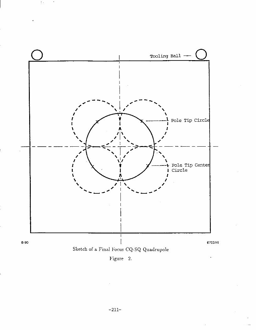
The Final Focus CQ-SQ Quad Pair
This magnet pair consisted of two 2001b solid steel cored magnets 5 inches long with a width of 10 inches and a height of 12 inches. The bore diam- eter was &inch and four tooling balls at the top corners served as external fiducials (Figure 2). The purpose of the CMM inspection was to check the op- tical tooling measurements taken before installation. Beam steering studies indicated possible errors in the original fiducials.
The inspected procedure consisted of scanning a sample of 1SO points per pole tip to determine the best fit circle for each pole tip surface.’ Another circle was fitted to the centers of the four pole circles to find a best fit geometric center. (Figure 2). This was repeated at both ends to set the X, Y and Z origins as well as the yaw and pitch angles. Roll was to be defined by the split plane.
The quality of the results were greatly diminished by the configuration of the magnet. Roll could not be accurately set because the split plane was not accessible. Attempts to use the centers of the pole tips to set the orientation proved unsuccessful due to the extremely short lever arm (1.5 inch). Also, tooling the CMM probe could not fully access all balls. The results which could be compared to previous measurements shoTTed discrepancies of up to 400pms. Since the CMM measurements did not repeat well and the geometry was poor, the results were discarded. Repeated optical tooling inspection showed changes in fiducial coordinates of up to 150pm. This illustrates that for this case neither method satisfied the 50pm inspection tolerance. *
The conclusion is that magnets should be designed with C>N measurable features. “After the fact” fiducialization may be difficult if not impossible for magnets without them. However, new video sy-stems technology may . improve this situation.
-20%
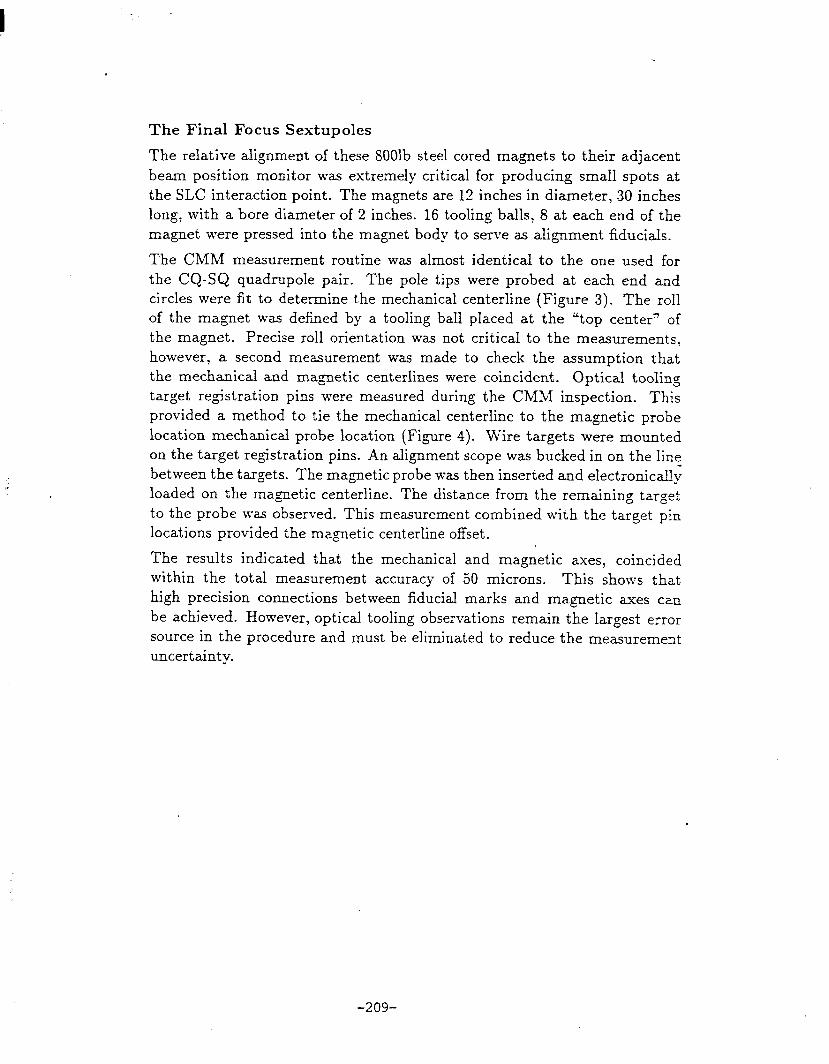
The Final Focus Sextupoles
The relative alignment of these 8OOlb steel cored magnets to their adjacent beam position monitor was extremely critical for producing small spots at the SLC interaction point. The magnets are 12 inches in diameter, 30 inches long, with a bore diameter of 2 inches. 16 tooling balls, 8 at each end of the magnet were pressed into the magnet body to serve as alignment fiducials.
The CMM measurement routine was almost identical to the one used for the CQ-SQ quadrupole pair. The pole tips were probed at each end and circles were fit to determine the mechanical centerline (Figure 3). The roll of the magnet was defined by a tooling ball placed at the “top center” of the magnet. Precise roll orientation was not critical to the measurements, however, a second measurement was made to check the assumption that the mechanical and magnetic centerlines were coincident. Optical tooling target registration pins were measured during the CMM inspection. This provided a method to tie the mechanical centerline to the magnetic probe location mechanical probe location (Figure 4). Wire targets were mounted on the target registration pins. An alignment scope was bucked in on the line between the targets. The magnetic probe was then inserted and electronically loaded on the magnetic centerline. The distance from the remaining target to the probe was observed. This measurement combined with the target pin locations provided the magnetic centerline offset.
The results indicated that the mechanical and magnetic axes, coincided within the total measurement accuracy of 50 microns. This shoKs that high precision connections between fiducial marks and magnetic axes can be achieved. However, optical tooling observations remain the largest error source in the procedure and must be eliminated to reduce the measurement uncertainty.
-209-

\
7
I L
\
--ID -D-
Scale scanning’
5-87 I 5754Al
Basic Components of a Coordinate Measu
Figure 1.
kg Machine
-210-
0 I Tooling Ball -- 1 0, I
I
\ I \
/
A /\
\
/ \ 8 \ 8
\ 0 \ 0
\ I \ /
I
I
L a-90 I
Sketch of a Final Focus CQ-SQ Quadrupole
6703%
Figure 2. .
-211-

5-a7
Sketch of a Sextupole Figure 3.
IO/ AL Analyser
Magnet Aliqnmen: Scape
Setup for the Determination of the Magnetic Centerline Figure 4.
-212-