abstract - solid freeform fabrication symposium base material used in the printing is visijet®...
TRANSCRIPT

Indirect Additive Manufacturing of a Cubic Lattice Structure with a Copper Alloy
1Jiwon Mun, 1Jaehyung Ju, and 2James Thurman
1Department of Mechanical and Energy Engineering, 1155 Union Circle #311098 2College of Visual Arts and Design, 1155 Union Circle #305100
University of North Texas, Denton, Texas 76203-5017
Abstract
Direct-metal additive manufacturing (AM) processes such as Selective Laser Melting (SLM) and Electron Beam Melting (EBM) methods are being used to fabricate complex metallic cellular structures with a laser or electron beam over a metal powder bed. Even though their excellent capabilities to fabricate parts with cellular mesostructure, there exist several constraints in the processes and applications; limited selection of materials, high thermal stress by the high local energy source, poor surface finish and anisotropic properties of parts caused by combined effects of one-dimensional (1D) energy based patterning mechanism, the deposition layer thickness, powder size, power and travel speed of laser or electron beam. In addition, manufacturing cost is still high with the Direct-metal AM processes. As an alternative way to manufacture metallic 3D cellular structures, which can overcome the disadvantages of direct-metal AM techniques, polymer AM methods can be combined with metal casting. We may call this “Indirect AM based Casting (I AM casting)”. The objective of the study is to explore the potential of I AM Casting associated with development of a novel manufacturing process - Indirect 3D Printing based casting which is capable of producing metallic cellular structures within a cell size of 3mm and cell thickness of 0.5mm. We will characterize polymers making sacrificial patterns by PolyJet typed 3D printers; e.g., melting and glass transition temperatures and thermal expansion coefficients. A transient flow and heat-transfer analysis of molten metal through 3D cellular network mold will be conducted. Solidification of molten metal through cellular mold during casting will be simulated with temperature dependent properties of molten metal and mold over a range of running temperature. The volume of fluid (VOF) method will be implemented to simulate the solidification of molten metal together with a user defined function (UDF) of ANSYS/FLUENT. Finally, experimental validation will be followed.
Introduction
Cellular metals are increasingly receiving attention for their having combinations of mechanical, thermal, and acoustic properties that provide potential opportunities for diverse multifunctional structural implementations. These include ultralight structures with high specific strength [1] and high specific strain [2], excellent impact absorption [3], acoustic insulation [4], heat dissipation media and compact heat exchangers [5].
In alignment with recently emerging 3D printing technologies [6], realization of their structural applications of cellular metals appears to become fast. Direct-metal additive manufacturing (AM) processes which use a laser or electron-beam over a metal power-bed are capable of manufacturing fully complex 3D cellular metallic structures. Selective Laser Melting [7], Electron Beam Melting [8], and Direct-Metal Laser Sintering [9] are the available direct AM processes to fabricate metallic cellular structures. However, in spite of their capability to fabricate parts with cellular geometries, there are still several constraints in the process, which limits their scalability to structural applications. For example, selection of materials is limited: e.g., aluminum alloys are challenging to process due to their high thermal conductivity and high optical reflectivity
665

[10]. Fabricated parts suffer from thermal residual stresses [11]. The 1D energy based patterning mechanism induces poor surface quality mainly by ‘balling’ phenomenon that occurs during laser or electron melting [12]. The ‘balling’ phenomenon limits the direct metal AM process resolution because it causes the formation of discontinuous track, which is responsible for a non-uniform deposition of material on the previous layers, thus inducing a possible porosity and delamination between layers that is detrimental to the functional performance of parts such as fatigue [12]. Direct-metal AM processes also induces anisotropic properties of parts caused by a combined effects of the deposition layer thinness and powder size, power and scanning speed of laser or electron beam [8]. In addition, both costs for machine and manufacturing are extremely high with the Direct-metal AM processes. For these reasons, it may be argued that direct-metal AM methods are not capable of fabricating cellular structural parts with a sufficient scale for structural applications.
As an alternative way to manufacture 3D cellular metals, which can overcome the disadvantages of direct-metal AM techniques, an AM of polymers can be combined with traditional casting methods. We may call this “Indirect AM based Casting (I AM Casting)”. I AM Casting has been introduced more than two decades ago but quantitative studies on this have not been fully conducted yet. I AM Casting can give more freedom in selecting materials, e.g., aluminum and magnesium cellular structures, with proper design of gate systems related to flow control of molten-metal. It can produce an isotropic property of cell walls. It can provide excellent surface quality, which is one of the strong advantages over the direct-metal AM methods. These all provide one with the potential to scale up the cellular metals and other multifunctional structural applications with relatively cheap cost due to the mass-production combined with reduced cost of pattern fabrication using automated 3D printing technologies, which were traditionally used with wax pattern through die casting in investment casting.
In spite of its scalable potential of periodic cellular metals to (multi)functional applications, the manufacturing methods of I AM Casting were not fully explored and understood. Only a few qualitative studies have been conducted. A tetrahedral Be-Cu alloy lattice structure, with a cell size of 10mm, was fabricated by investment casting of an ABS sacrificial cellular pattern printed by a Fused Deposition Modeling (FDM) method [13]. Recently, a research group reported a sand casting of cellular structures, whose cell size is about 25mm x 50mm [14] and significant casting porosity was reported. This appears to be associated with network structures with sharp corners of cellular structural molds that may prevent fluid-flow and undesired solidification, resulting in mis-run and porosity.
In this study, we explore a new I AM Casting method to build a cellular structure by combining 3D printing of cellular patterns by a polyJet method and centrifugal casting. A transient flow and heat-transfer analysis of molten copper alloy through 3D cellular network mold will be conducted with a sprue system. Solidification of molten metal through cellular mold during casting will be simulated with temperature dependent properties of molten metal and mold over a range of running temperature. The volume of fluid (VOF) method will be implemented to simulate the solidification of molten metal together with a user defined function (UDF) of ANSYS/FLUENT, which will be experimentally compared.
Preparation of Sacrificial pattern with Additive Manufacturing
In this section, we present a method to produce a 3D cellular pattern fabricated by a 3D printer. A polyjet type professional 3D printer (ProJet™ HD 3500 Plus, 3D Systems) was used to produce a cellular sacrificial pattern. The base material used in the printing is VisiJet® Procast, a castable plastic. The supporting material used for 3D printing is VisiJet® S300, a wax material for
666

hands-free melt away supports.
Figure 1: Stress-strain curve of VisiJet® Procast under a
uniaxial load at a strain rate of 0.001
Figure 2: DSC curve of VisiJet® Procast
Mechanical Properties: A 3D printed dumbbell-shaped sample is prepared according to
ASTM D638 with an extra high resolution printing mode (16 resolution and 750x750x1600 DPI in the x, y, and z directions). A uniaxial test using a universal testing machine (AGS-X Series, Shimadzu) with a load cell of 5kN and a strain rate of 0.001/s shows a modulus of 549MPa and a yield strength of 8.7MPa (Figure 1), which is about 2-20 times higher than waxes in modulus and strength. It should be noted that waxes have been generally used as materials for building sacrificial patterns in investment casting [15]. The relatively high modulus of the base material of a 3D printer is preferred to the conventional wax materials for fabricating 3D cellular sacrificial patterns with thin walls because the patterns need to bear loads by ceramic slurry or plaster coating.
Thermal analysis: For planning burning out of sacrificial patterns, estimation of melting temperature is necessary. We conducted thermal analysis of VisiJet® Procast with a Differential Scanning Calorimeter (DSC). It shows a melting temperature of (Figure 2). For a reference value, a wax material’s melting temperature was also measured ( ) with DSC as well. In general, waxes have been popular as a material for fabricating sacrificial patterns due to its low melting temperature so that one can easily melt away the wax patterns during the burning out processing to make ceramic mold. The relatively high melting temperature of VisiJet® Procast is not favorable but it can be manageable.
Thermal expansion coefficient of VisiJet® Procast was measured with a thermo mechanical analyzer (TMA4000, PerkinElmer); ⁄ which is 140 times lower than that of wax ( ⁄ ). This shows that VisiJet® Procast has the potential to avoid thermal stress related cracking which is generally observed with a wax pattern during burning out process. Even considering its relatively high melting temperature of , VisiJet® Procast has about 30 times lower thermal strain than that of wax materials. The density of VisiJet® Procast is ⁄ , which is 30% higher than that of wax ( ⁄ ).
0
5
10
15
20
25
0 0.05 0.1 0.15
Stre
ss (
MP
a)
Strain
0
5
10
15
20
25
30
0 100 200 300 400 500
He
at F
low
(m
W)
Temperature (oC)
𝑇𝑔 = 97.59 oC
𝑇𝑚
= 337.11 oC
667

Figure 3: CAD model of a sacrificial pattern of a 3D
cellular structure
Figure 4: A cellular structural pattern fabricated by a polyjet type
3D printer with VisiJet® Procast
CAD drawing and printing: A complex 3D network cellular structure is pursued to cast
with pattern fabricated by additive manufacturing. A computer aided design (CAD) model for the sacrificial pattern of a 3D cellular solid is generated with commercial CAD software, Pro-E, as shown in Figure 3. All necessary dimensions of the 3D cellular pattern are indicated in Figure 3. Figure 4 shows a cellular structural pattern with internal channels manufactured by a polyjet type 3D printer (ProJet™ HD 3500 Plus) with VisiJet® Procast. The average thickness of the 3D sacrificial pattern is 1.016mm and the standard deviation is 0.027mm.
In terms of its high modulus and low thermal expansion coefficient, VisiJet® Procast has the potential to be used as a base material for fabricating cellular structural sacrificial patterns over conventional wax materials. Especially, the high modulus is good for building cellular structural patterns with thin cell walls and the low thermal expansion coefficient is favorable for lowering thermal stress during the burning out process of the sacrificial pattern.
Preparation of a Plaster Mold System
After building cellular patterns from additive manufacturing, a mold for an assembled sacrificial lattice pattern with a sprue system is prepared. Gypsum (CaSO4
H2O) (Satin Cast
20™, FindingKing Kerr) is used for mold preparation of 3D cellular structural plaster mold.
Figure 5 shows the procedure of the preparation of the mold. First, Satin Cast 20TM was weighed for the plaster mold as shown in Figure 5 (1). Then, the quantity of water for mixture with investment was determined, which is recommended to add 40 ml water to 100 g investment powder as shown in Figure 5 (2). Water of was added to investment powder in this experiment as shown in Figure 5 (3). At the fourth stage as shown in Figure 5 (4), water and investment powder was mixed with water. Adding and mixing investment powder to water stage through stage (3) to (4) were conducted for 3.5 minutes by recommended work time. After mixing water and investment powder together, this mixture was placed in a vacuum chamber for 2.5 minutes in order to remove the remained air bubbles inside of the mixture as shown in Figure 5 (5). Then, the sacrificial pattern is prepared as shown in Figure 5 (6) and it is covered with a flask as shown in Figure 5 (7). The investment mixture in the vacuum chamber is taken out and is poured into the flask as shown in Figure 5 (8). Then, in order to get rid of the air bubbles inside the flask, the flask with mixture was vacuumed again in the vacuum chamber for 1.5 minutes as shown in Figure5 (9). Then, it is placed outside for two hours to be solidified (Figure 5 (10)). For the burning out process; the furnace was preheated at a temperature of as shown in Figure 5 (11). The flask was placed into the furnace at a temperature of for 2 hours as shown in Figure 5 (13) after removing sprue base as shown in Figure 5 (12). The burning out procedure is as follows; for 2 hours for 2 hours for 2 hours for 4 hours and for 2 hours.
668

Figure 5: Procedure for preparation of a plaster mold
After mixing VisiJet® Procast is burnt out and only a gypsum plaster mold cavity is left. Table 1 shows thermal and mechanical properties of the gypsum plaster mold. Those properties will be used for simulation in Section 4.
Table 1: Material properties of gypsum plaster mold
Property Value (unit) Density at 650
Thermal conductivity at 0.47 Specific heat [31] 1
Roughness [ ] Thermal expansion coefficient
Preheated temperature Heat diffusivity [31]
Centrifugal Casting
Experimental Once the cellular structural plaster mold is prepared, molten metal is prepared for casting.
The chemical composition and properties of the molten copper alloy (Jewelry Bronze) are shown in Tables 2 and 3, respectively [16]. Cu is the dominant chemical composition of the material.
Table 2: Chemical composition of the bronze tested in this study [16]
Material Unit
Cooper alloy (Jewelry bronze)
Chemical Composition (%max, unless shown as range or mean)
Cu Si Zn Mg Pb Min./Max. 91.9 4.0 4.0 0.25 Max 0.25 Max
669
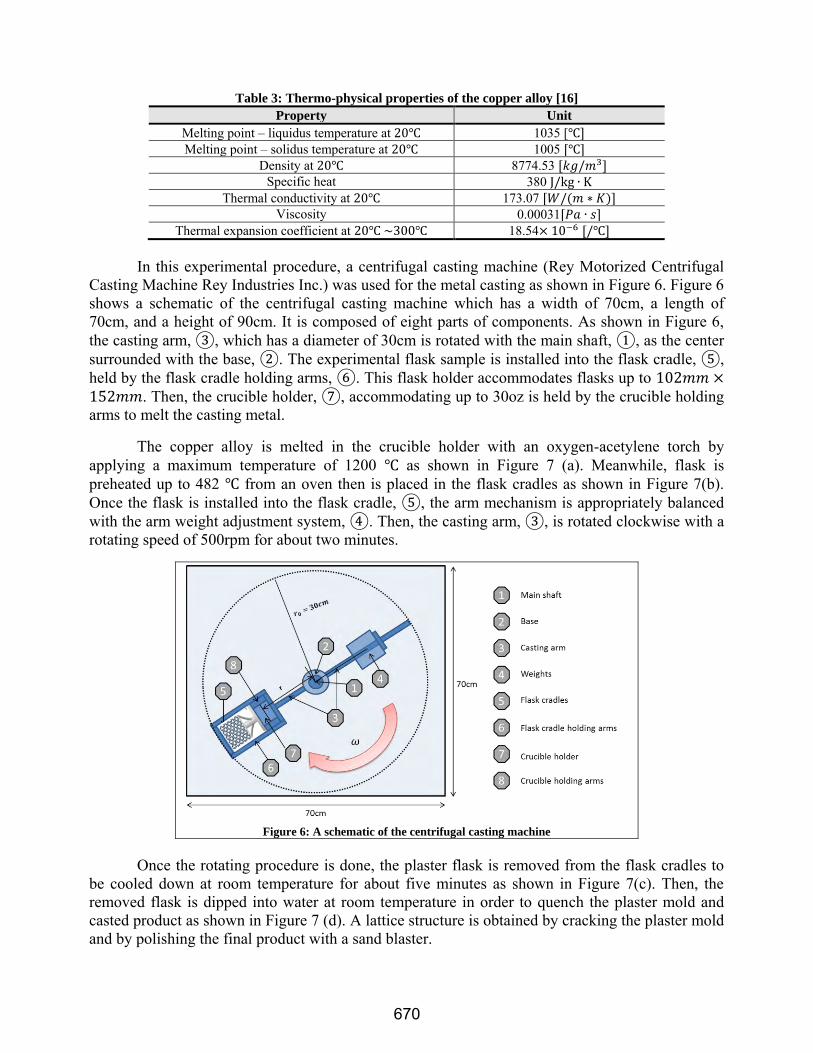
Table 3: Thermo-physical properties of the copper alloy [16]
Property Unit
Melting point – liquidus temperature at 1035 [ Melting point – solidus temperature at 1005
Density at 8774.53 Specific heat 380
Thermal conductivity at 173.07 Viscosity 0.00031
Thermal expansion coefficient at 18.54 In this experimental procedure, a centrifugal casting machine (Rey Motorized Centrifugal
Casting Machine Rey Industries Inc.) was used for the metal casting as shown in Figure 6. Figure 6 shows a schematic of the centrifugal casting machine which has a width of 70cm, a length of 70cm, and a height of 90cm. It is composed of eight parts of components. As shown in Figure 6, the casting arm, ③, which has a diameter of 30cm is rotated with the main shaft, ①, as the center surrounded with the base, ②. The experimental flask sample is installed into the flask cradle, ⑤, held by the flask cradle holding arms, ⑥. This flask holder accommodates flasks up to . Then, the crucible holder, ⑦, accommodating up to 30oz is held by the crucible holding arms to melt the casting metal.
The copper alloy is melted in the crucible holder with an oxygen-acetylene torch by applying a maximum temperature of 1200 as shown in Figure 7 (a). Meanwhile, flask is preheated up to 482 from an oven then is placed in the flask cradles as shown in Figure 7(b). Once the flask is installed into the flask cradle, ⑤, the arm mechanism is appropriately balanced with the arm weight adjustment system, ④. Then, the casting arm, ③, is rotated clockwise with a rotating speed of 500rpm for about two minutes.
Figure 6: A schematic of the centrifugal casting machine
Once the rotating procedure is done, the plaster flask is removed from the flask cradles to
be cooled down at room temperature for about five minutes as shown in Figure 7(c). Then, the removed flask is dipped into water at room temperature in order to quench the plaster mold and casted product as shown in Figure 7 (d). A lattice structure is obtained by cracking the plaster mold and by polishing the final product with a sand blaster.
670

Figure 7: Centrifugal casting procedure
The final product of the lattice structure is shown in Figure 8. As shown in Figure 8 (a), (b),
and (c), very few defects such as mis-run, metal penetration, and air gap were detected and the molten metal filled the plaster mold cavity well. It is known that copper alloys fill the mold cavity well during centrifugal casting due to its high density and low viscosity [17]. On the other hand, it is known that aluminum and magnesium alloys with low density and high viscosity are difficult to fill the mold cavity during centrifugal casting [17]. The thickness of the final product is 1.012mm and the standard deviation is 0.077mm.
(a)
(b)
(c)
Figure 8: Final product and defects
The final product by the centrifugal casting shows a smooth surface. Direct additive manufacturing methods such as selective laser melting (SLM) and electron beam melting (EBM) are known to have poor surface quality in the parts due to the one dimensional (1D) energy based patterning mechanism combined with the deposition layer thickness, powder size, power and travel speed of laser or electron beam [12]. Due to the poor surface quality, SLM and EBM need a post-process for surface polishing. On the other hand, the indirect AM based casting method shows a promising surface finish.
Modeling and Simulation of Centrifugal Casting
Hydrodynamics of the molten metal flow in the lattice structure
671
Flow of molten metal into the cellular structural mold is estimated using fluid simulation. An inlet velocity into the mold is estimated from the radial speed of the centrifugal machine. Considering the angular speed of 500rpm of the rotating arm, the radial speed of fluid particle is obtained.
= √ (1)
where, is the velocity of the molten metal in the radial direction, is the angular velocity of the rotating arm in ⁄ , is the radius of the casting arm and is the released distance of the weight from the origin of the casting arm. The radial velocity , into the cellular plaster mold and sprue system is obtained as from Equation (1).
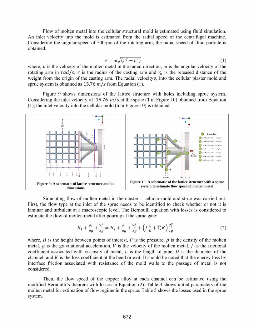
Figure 9 shows dimensions of the lattice structure with holes including sprue system. Considering the inlet velocity of ⁄ at the sprue (1 in Figure 10) obtained from Equation (1), the inlet velocity into the cellular mold (5 in Figure 10) is obtained.
Figure 9: A schematic of lattice structure and its
dimensions
Figure 10: A schematic of the lattice structure with a sprue
system to estimate flow speed of molten metal
Simulating flow of molten metal in the cluster – cellular mold and strue was carried out. First, the flow type at the inlet of the sprue needs to be identified to check whether or not it is laminar and turbulent at a macroscopic level. The Bernoulli equation with losses is considered to estimate the flow of molten metal after pouring at the sprue gate:
𝑔
𝑔=
𝑔
𝑔 (
∑ )
𝑔 (2)
where, is the height between points of interest, is the pressure, is the density of the molten metal, is the gravitational acceleration, is the velocity of the molten metal, is the frictional coefficient associated with viscosity of metal, is the length of pipe, is the diameter of the channel, and is the loss coefficient at the bend or exit. It should be noted that the energy loss by interface friction associated with resistance of the mold walls to the passage of metal is not considered.
Then, the flow speed of the copper alloy at each channel can be estimated using the modified Bernoulli’s theorem with losses in Equation (2). Table 4 shows initial parameters of the molten metal for estimation of flow regime in the sprue. Table 5 shows the losses used in the sprue system.
672

Table 3: Losses used in the lattice structure in Figure 10
Section Relative
roughness
Friction Coefficient (Moody chart) Minor losses coefficient
1-2 Sudden contraction + entry = = 2-3 No minor losses =
3-4 Sudden contraction + entry loss = =
The flow speed of the molten metal at each channel can be estimated using the modified Bernoulli’s equation with geometric loss values in Table 5. The corresponding Reynolds numbers were obtained to determine the flow type at each point [18, 19]. It is found that the flow is turbulent through the entire sprue. Two cases of inlet velocity at the gate of the cellular plaster mold are used; 5 and 0.005 for Case 1 and Case 2, respectively, as obtained from Table 6. Flow simulations without the sprue system are followed with the different inlet velocities as shown in Figure 10.
Critical inlet velocity exists to overcome solidification inside of the mold, which is one of the important parameters to avoid casting defects such as mis-run, metal penetration, and air gaps including gating design, initial melting temperature of the liquid metals, etc. [17], in which the laminar is used for the flow type of the liquid metal based on the calculation of the Reynolds number ( = .
Table 4: Reynolds numbers to identify flow type
Section Velocity Magnitude ( ) Reynolds number 1-2 = 𝑇 2-3 = 𝑇 3-4 = 𝑇 4-5 = 𝑇
5 Case 1 Case 2 Case 1 Case 2 = = 𝑇
Estimation of heat transfer in the lattice structure with sprue system
In order to estimate the type of the heat transfer for the numerical simulation, Prandtl
number, Rayleigh number, and Nusselt number were calculated using the initial conditions in Table 7.
The Pandtl number can be calculated using Equation (3) [20].
=
=
𝑚 =
(3)
where, is the kinematic viscosity ( = , is the thermal diffusivity ( =
) , is the
dynamic viscosity, is the thermal conductivity, is the specific heat, and is the density. From Equation (3), we obtain a Prandtl number of for Case 1 and for Case 2, which indicates that conduction is dominant compared with the heat convection as shown in Table 8 for Case 1 and Case 2.
The Rayleigh number is calculated from the relation with Prandtl number [20];
673

=𝑔
𝑇 𝑇 = (4)
where, is the characteristic length, is the Rayleigh number at position , is the Grashof number at position , is the Prandtl number, is the gravitational acceleration, 𝑇 is the surface temperature (temperature of the wall), 𝑇 is the ambient temperature , is the kinematic viscosity, is the thermal diffusivity, and is the thermal expansion coefficient. The Rayleigh number obtained from Equation (4) is for Case 1 and for Case 2, which indicates the conduction flow is dominant and air by natural convection on the mold surface is a laminar flow for both cases, as indicated in Table 8.
The Nusselt number can be calculated as follows [20, 21]:
=
= =
(5)
where, is the characteristic length, is the thermal conductivity of the fluid, is the convective heat transfer coefficient, is the Reynolds number, is the Prantld number, and is the for heating and for cooling. Here, the casting mold is cooled at room temperature, = is used for this study. The Nusselt number obtained from Equation (5) is for Case 1 and for Case 2, which indicates that the flow type of heat transfer type is conduction for the both cases as well. Therefore, based on the calculation of the Reynolds, Rayleigh, Prandtl, and Nusselt numbers, the flow type of the molten metal can be considered turbulent and conduction for Case 1 and laminar and conduction for Case 2 are the dominant heat transfer mode in this study.
Table 5: Initial conditions for the numerical simulation
Initial conditions Value (unit)
Injection velocity (linear velocity) Case 1 Case 2
0 Initial temperature of the inlet
Flow regime Turbulent Laminar
Table 6: Heat transfer criterion for flow regime justification
Criteria Value Justification for numerical approach
Case 1 Case 2 Case 1 Case 2 Prandtl number
Conduction
Rayleigh number
Conduction
Nusselt number
Conduction
Flow simulation through the lattice structural mold
Once we obtain the initial velocity of molten metal at the gate of the plaster mold for both cases, we go into the estimation of the metal flow in the lattice structural mold. A commercial finite difference (CFD) code, ANSYS/FLUENT, is utilized to simulate the liquid metal casting to the cellular structural mold [19, 22]. A fully developed turbulent velocity profile for Case 1 and a fully developed laminar velocity profile were applied at the inlet as well as the entire lattice
674

structural mold, which were determined through the criteria of Reynolds number whose velocity input was estimated by the energy equation. An unsteady momentum equation coupled with the unsteady heat transfer (energy equation), the turbulence equations, species equations, and back diffusion equations are applied to solve fluid problems involving solidification of cooper alloy (jewelry bronze) through the cellular structural mold cavity. A Newtonian flow is applied to the simulation under an incompressible condition of the liquid metal.
Homogeneous and isotropic properties of molten metal in solid and liquid phases whose properties are shown in Table 3 are applied to the simulation. A conduction heat transfer is applied to the simulation based on the estimation of heat transfer determined by the Rayleigh, Prandtl, and Nusselt numbers. Surface roughness (2.5 micron) as shown in Table 1 on the wall of the plaster mold is neglected during the simulation for simplifying the problem in our initial attempt to study simulation of molten metal in the cellular structural plaster mold.
Figure 11: A schematic of flow simulation of a molten metal in the lattice structural mold
Coarse meshes consisting of 1,461,875 elements and 352,218 nodes with a minimum mesh
size of and a maximum mesh size of are generated for the flow simulation for both cases. The properties of plaster mold used for the cellular structural plaster mold are shown in Table 1. The constant values of physical properties, e.g. viscosity, density, thermal conductivity, etc., have been used for the simulation of metal casting in spite of their variation with temperature during casting due to the difficulties in implementing temperature dependent properties in the simulation [23]. This may mislead the solidification, resulting in underestimation of solidification of molten metals which are typically experiencing a temperature varying of ~200C. If the molten metal flows through thin tubes, which is the case of this study with a lattice structural mold, the solidification may be more sensitive to temperature due to more surface area exposed to air.
Therefore, a user-defined function (UDF), a used subroutine of ANSYS/FLUENT, where one can implement temperature dependent properties of the molten metal. Temperature dependent properties of viscosity, density, and thermal conductivity for the molten copper alloy were employed as the input values of the simulation using UDF in ANSYS/FLUENT [19, 24].
Continuity and Momentum Equations for fluid flow
The continuity equation for unsteady fluid flow can be written as follows:
= 𝑚 (6)
where, is the density of fluid, is the velocity vector, and 𝑚 is the mass added to the continuous phase from the dispersed second phase due to the phase change. Here, 𝑚 can be any user-defined source terms according to the problems [19].
The conservation of momentum can be described by 675

= (7)
where, is the static pressure, is the stress tensor, is the gravitational body force, and is the external body force. Also, can contain other model-dependent source terms such as user-defined sources.
Volume of fluid (VOF) method for flow fill
To describe and track the interphase between the solid and the liquid phases, the VOF method was used. This enables to track the transition of the interfaces with arbiter topology and deformation [19, 25]. To define the fractional volume of each phase in the computation domain, the time derivative of is expressed as:
= (8)
This function has a range from zero to the unity . = indicates that a cell contains no fluid, = indicates the interphase between liquid and solid phases, and = means that a cell is full of fluid.
Simulation of solidification
The fluid flow problems involving solidification taking place at one temperature for pure metals or over a range of temperatures for binary alloys. In this study, an enthalpy-porosity method for the solidification is used instead of tracking the liquid-solid front (VOF method) explicitly [26]. This means that the liquid-solid phase (mush zone) is treated as a porous zone with porosity equal to the liquid fraction [19].
The conservation of energy equation can be written as follows [27]:
= (
) (9)
where, is the source term, is the sensible enthalpy, is the thermal conductivity, and is the specific heat.
The source term derived by Benon and Incropera for a two-phase system can be written as [27]:
= [
] (10)
where is the thermal conductivity, is the specific heat of the solid phase, is the sensible enthalpy of the solid phase of the solid phase, is the sensible enthalpy, is the mass fraction of the solid phase, is the velocity vector, is the velocity vector of the solid phase, is the sensible enthalpy of the liquid phase, and is the sensible enthalpy of the liquid phase.
The momentum source in liquid, mush zone (liquid + solid), and solid phases can be written as follows, respectively [27].
=
(11)
𝑚 =
𝑚 (12)
676

= (13)
where, is the dynamic viscosity, is the liquid volume fraction, is a small number (0.001) to prevent division by zero, 𝑚 is a mushy zone constant, is the velocity vector, and is a constant. The momentum source is proportional to the x, y, and z components of the velocity vector , which has the opposite sign, therefore [19, 27]:
= (14)
This means that its motion will be reduced to zero (no velocity) as the liquid cools down, implying formation of solid. So, the derivative of Equation (14) with respect to velocity vector
becomes a constant or zero. For the temperature-dependent viscosity one needs to assume that liquid becomes more viscous as liquid cools down and its velocity decreases, which implies solidification. The used equations for the temperature-dependent density, viscosity, and thermal conductivity of the copper alloy are shown in Figures 12 through 14.
The energy equation for heat transfer is given by
𝑇 =
(15)
where, 𝑇 is the temperature, is the density, is the specific heat, and is the thermal conductivity. In general, viscosity of a material decreases with temperature. Viscosity of the copper alloy as a function of temperature is plotted in Figure 12.
Figure 12: Temperature-dependent viscosity of molten copper alloy [22, 24]
Density decreases with temperature due to the increase in volume. The reason on the rapid
decrease between in Figure 13 is due to the phase transformation from liquid phase to solid phase. In the solid phase, the volume which contains atoms is smaller than that of liquid phase.
0.0010
0.0015
0.0020
0.0025
0.0030
0.0035
0.0040
0.0045
0.0050
0.0055
0.0060
800 1000 1200 1400 1600 1800
Vis
coci
ty, K
g/m
-s
Temperature, C◦
677

Figure 13: Temperature-dependent density of the molten copper alloy [28]
Many literatures studied about temperature-dependent thermal conductivity for liquid metal
or alloys. It has been shown that thermal conductivity of liquid metal deceases when its temperature reaches melting point on the assumption that the frequency of vibration of molecules changes near the melting point [29].
In many cases, a constant thermal conductivity of molten metal has been used for estimating flow and solidification of molten metal [29]. However, it appears that one needs be careful to implement the thermal conductivity of the molten copper alloy: As can be seen in Figure 14, thermal conductivity is highly nonlinear over a range of 860-980 , which may cause a significant difference in the solidification in molten metal.
Figure 14: Temperature-dependent thermal conductivity of the copper alloy[30]
An overall numerical scheme on simulation of molten metal’s flow and solidification
coupled with heat transfer is illustrated with a flow chart in Figure 15. Both flow and heat transfer equations are iterated with updated temperature-dependent properties until the temperature reaches the solidification (1,005 ) of the molten copper alloy.
From a preheating temperature of 482 to the solidified temperature of the molten copper alloy, temperature-dependent material properties are updated to both flow and heat transfer equations.
6500
6700
6900
7100
7300
7500
7700
7900
8100
8300
8500
800 1000 1200 1400 1600 1800
De
nsi
ty, k
g/m
^3
Temperatue, C◦
0
20
40
60
80
100
120
140
160
180
800 1000 1200 1400 1600 1800
Co
nd
uct
ivit
y, W
/m-k
Temerature, C◦
678

Figure 15: A flowchart on the computation of casting using UDF and internal solidification function
The initial temperature of the copper alloy and the entire plaster mold were maintained as
1200 and 482 , respectively. The time step size used in the simulation was 0.01 . The computational time was about 72 hours with an Intel ® Xeon® CPU E5603 @ 1.60GHz (2 processors) and 24.0 GB RAM.
Simulation Results
Simulation of Flow-fill
Flow-fill of molten metal through a cellular structural mold is simulated as a function of time. Figures 16 and 17 show the volume fraction of the molten copper alloy as a function of time when the temperature dependent material properties for density, viscosity, and thermal conductivity for molten jewelry were applied.
Figure 16: Simulation of flow-fill at the plane a for Case 1 (Turbulent flow)
Figure 16 shows the simulation of flow-fill at a plane along the flow direction for Case 1 with the turbulent velocity flow type. It takes about to fully fill the cellular structural mold with the molten metal with an initial inlet velocity of . Mis-run is detected near the edge (top and bottom) of the cellular structure. The flow-filling pattern shows that the molten metal is first filled in the x direction, followed by filling in the y direction as shown in Figure 16.
Figure 17 is the simulation results of flow-fill at the center plane perpendicular to the flow for Case 1. The filling time is the same with that at the xz-plane. Symmetric flow profile is
Flow direction
679

observed with mis-run at the edge of the lattice mold.
0 s
1.5 s
2.0 s
3.0 s
Figure 17: Simulation of flow-fill at the xz-plane for Case 1 (Turbulent flow)
Figures 18 and 19 show the flow-filling of the copper alloy for Case 2 with the laminar
flow type as a function of time when the temperature dependent material properties of the molten copper alloy were applied. Figure 18 shows the simulation of flow-fill at a plane along the flow direction for Case 2. It takes about to fully fill the cellular structural mold with the molten copper alloy with an initial inlet velocity of .
Figure 18: Simulation of flow-fill at the xz-plane for Case 2 (Laminar flow)
Figure 19 shows the simulation results of flow-fill at the center plane perpendicular to the flow. It takes about to fill the cellular structural mold with the molten meal with an initial velocity of . Even though it took about to fill the structural mold at point 5, the casting defect often called mis-run (blue part) was detected. This is due to the slow velocity of the molten copper alloy at the inlet.
Flow direction
Flow direction
680

Figure 19: Simulation of flow-fill at the xy-plane for Case 2 (Laminar flow)
Solidification (Liquid fraction)
Transient solidification of the molten copper alloy through the cellular structural mold is simulated with the temperature-dependent material. Figures 20 through 24 shows the volume fraction of the copper alloy for Case 1 with the turbulent flow type and Case 2 with laminar flow type as a function of time when the temperature dependent material properties for density, viscosity, and thermal conductivity for molten copper alloy were applied.
Figure 20 shows the simulation of transient solidification at the xy-plane along the flow direction for Case 1 with the turbulent velocity profile. The red color represents the liquid phase and blue color means the solidified molten metal. It shows that the molten metal becomes solidified as soon as it passes through the lattice mold.
.
Figure 20: Simulation of transient solidification at the xy-plane a for Case 1 (Turbulent flow)
Figure 21 shows the simulation results of the transient solidification at the center plane perpendicular to the flow. Also, the solidification shows similar tendency with that from Figure 20. Also, it can be seen that air gaps, unfilled empty part, at the edge of the cellular mold, were detected.
Flow direction
Flow direction
681

Figure 21: Simulation of transient solidification at the xz-plane for Case 1 (Turbulent flow)
Figure 22 is the simulation of transient solidification at the xy-plane along the flow
direction for Case 2 with the laminar velocity profile. Even though the molten metal was fully filled, many air gaps (red colored parts) were detected as shown in Figure 22.
Figure 22: Simulation of transient solidification at the xy-plane for Case 2 (Laminar flow)
Figure 23 shows the simulation results of the transient solidification at the center plane perpendicular to the flow. Similarly, many air gaps are shown inside of the cellular mold as shown in Figure 23. The solidification along the flow direction is more developed compared to that at perpendicular direction to the flow, which is due to the fact that the velocity magnitude is decreased with the converting of the molten metal flow inside of the cellular mold.
Flow direction
Flow direction
Flow direction
682

Figure 23: Simulation of transient solidification at the xz-planefor Case 2 (Laminar flow)
Flow-filling time for Case 1 with the turbulent flow regime showed faster filling time compared to that of laminar flow type, as expected. As well as, air gaps at the edges of the cellular structure were detected for Case 1 (turbulent flow). On the other hand, more air gaps were detected which is relatively more spread in overall cellular structure as shown in Figures 22 and 23, which causes degradation in the mechanical properties such as strength, toughness, and etc. this might due to the fact that the initial inlet velocity of the molten metal is not high enough to flow through thin circuit of the cellular structure and to overcome parameter affecting the fluidity such as surface roughness, friction, and etc.
In order to systematically analyze the solidification, liquid fraction (the degree of solidification) of the five points are monitored with the flow-filling time during the simulation time for the both of Case 1(turbulent flow) and Case 2 (laminar flow), as shown in Figures 24 through 29.
Figures 24 and 25 show the flow-filling time for both Case 1 (turbulent flow) and Case 2 (laminar flow) at the local points of interest, respectively. Filing time and the solidification time at the local points of interest can be obtained from the flow-fill simulation. Figure 24 shows the filling time from the local points ① to ⑤ as shown on the left in Figure 24, respectively. From Figure 24, it is shown that flow-filling time of the molten copper alloy in the cellular structural plaster mold is about 2s. Once molten copper alloy passes the points of interest, it cools down and solidification occurs. The flow-filling time at each point of interest for Case 1 with the turbulent flow regime is obtained; 0.08s at point 1, 1.1 s at point 2, 2.01s at point 3, 3.86 at point 4, and 4.31 at point 5. The flow-filling time at each point of interest for Case 2 with the laminar flow regime is obtained; 0.35s at point 1, 5.25s at point 2, 9.2s at point 3, 10.35 at point 4, and 20.1 at point 5. It can be obviously seen that the flow-filling time is faster for Case 1 with the turbulent flow type rather than case 2 with laminar flow regime. This is important parameter affecting on the casting process to reduce the casting defects such as mis-run, metal penetration, air gap, and etc.
Figure 24: Flow-filling time for Case 1 (Volume fraction for turbulent flow)
0
0.2
0.4
0.6
0.8
1
0 1 2 3 4 5
Vo
lum
em
fra
cio
n (
%)
Flow time (s)
Point 1Point 2Point 3Point 4Point 5
683

Figure 25: Flow-filling time for Case 2 (Volume fraction for laminar flow)
Figures 26 and 27 show the solidification time for both Case 1 (turbulent flow) and Case 2 (laminar flow) at the local points of interest, respectively. Also, the local solidification time at each point of interest for Case 1 is also obtained; 4.18s at point 1, 2.98s at point 2, 2.27s at point 3, 0.23 at point 4, and 0.01 at point 5. for Case 2 with the laminar flow, the local solidification time at each point of interest is; 22.2 s at point 1, 3.95s at point 2, 1.05s at point 3, 0.5s at point 4, and 0.13s at point 5.
Figure 26: Solidification time for Case 1 (Turbulent flow)
Figure 27: Solidification time for Case 2 (Laminar flow)
According to the monitored solidification time at the points of interest, the global and local solidification time at the five points were represented for Case 1 (turbulent flow) and Case 2 (laminar flow), as shown in Figure 28 and 29, respectively. Figure 28 shows the flow-filling time and solidification time on the points of interest for Case 1 (turbulent flow) as a function of time. The global and local solidification for the both cases shows similar tendency as shown in Figure 28 and 29. However, as represented Figures 28 and 29, it is shown that faster solidification occurs for Case 2 (laminar flow), in particular at point 2. There is limit in the initial injection velocity of the molten metal for the casting process to overcome faster solidification. That is, if the initial injection velocity of the molten metal at inlet of the casting mold is not enough faster to go through entire casting mold, the molten metal cannot be filled inside the casting mold causing faster solidification.
0
0.2
0.4
0.6
0.8
1
0 5 10 15 20 25
Vo
lum
e r
acti
on
(%
)
Flow time (s)
Point 1
Point 2
Point 3
Point 4
0
0.2
0.4
0.6
0.8
1
0 1 2 3 4 5
Liq
uid
fra
ctio
n (
%)
Flow time (s)
Point 1Point 2Point 3Point 4Point 5
0
0.2
0.4
0.6
0.8
1
0 5 10 15 20 25
Liq
uid
fra
ctio
n (
%)
Flow time (s)
Point 1Point 2Point 3Point 4Point 5
684

Figure 28: Flow-filling time and solidification time on the points of interest for Case 1 (Turbulent flow)
Figure 29: Flow-filling time and solidification time on the points of interest for Case 2 (Laminar flow)
Concluding Remarks
An indirect additive manufacturing method combining 3D printing technology and centrifugal casting was suggested and was implemented to manufacture a 3D cellular structure with a quantitative study on flow simulation of molten metal. A 3D cellular structural pattern was built with 3D printing of VisiJet® Procast, followed by molding and centrifugal casting. Centrifugal casting with copper alloy was conducted to fill the cellular structural mold cavity made of a gypsum plaster in the experiment. Filling and solidification during the centrifugal casting process were simulated in the plaster mold over a range of running temperature ( ). Temperature-dependent material properties of molten metal were applied for simulation of filling and solidification using a user defined function (UDF) in ANSYS/FLUENT. The major findings through this study are Additive manufacturing can be used for building sacrificial patterns of 3D cellular structures
for casting. VisiJet® Procast has the potential to be used as a base material for manufacturing sacrificial pattern over conventional wax materials due to its high modulus and low thermal expansion coefficient: These properties are especially good for making for building cellular structural patterns with thin cell walls and lowering thermal stress during the burning out process of the sacrificial pattern, respectively.
I AM Casting shows an excellent surface quality, which can be used for manufacturing cellular structures.
A coupled flow and heat transfer of molten metal successfully simulated flow-fill and solidification and is compared with the experiment.
More mis-runs were detected in overall cellular structure for the simulation with the laminar flow regime. On the other hand, fewer mis-runs were observed with the faster flow-filling time
0
1
2
3
4
5
1 2 3 4 5
Tim
e (
s)
Point of interest
Flow-filling time
Solidfiicatioin time (Golbal)
Solidfiicatioin time (local)
0
5
10
15
20
25
1 2 3 4 5
Tim
e (
s)
Point of interest
Flow-filling time
Solidfiicatioin time (Golbal)
Solidfiicatioin time (local)
685

at the edges of the cellular structure for the simulation with the turbulent flow regime of the velocity profile.
It is required to get limitation in the initial injection velocity of the molten metal to avoid faster solidification and to overcome bad fluidity of the molten metal for the casting process.
The present study with copper alloy will be extended to other metallic alloys for manufacturing light -weight and multifunctional cellular structures in near future.
Acknowledgements
The study received support the Research Initiation Grant (RIG) of the Vice President for Research and Economic Development at the University of North Texas (UNT). The authors also thank KCIS Co. Ltd for partially supporting this study.
References [1] Gibson L.J. and Ashby, M. F., 1997, “Cellular Solids-Structure and properties”, Cambridge University Press, Cambridge, UK. [2] Ju, J., Summers, J.D., Ziegert, J., and Fadel, G., 2012, “Design of Honeycombs for Modulus and Yield Strain in Shear", Transactions of the ASME: Journal of Engineering Materials and Technology, 134(1):011002. [3] Tan, H. and Qu, S., 2010, “Chap 6: Impact of Cellular Materials”, Cellular and Porous Materials in Structures and Processes”, CISM International Centre for Mechanical Science, Springer. [4] Phani, A. S., Woodhouse, J., Fleck, N.A., 2006, “Wave Propagation in Two-Dimensional Periodic Lattices”, Journal of Acoustical Society of America, 119(4), pp. 1995-2005. [5] Kumar, R. S., and McDowell, D.L., 2004, “Rapid Preliminary Design of Rectangular Linear Cellular Alloys for Maximum Heat Transfer”, AIAA Journal, 42(8), pp. 1652-1661. [6] Kruth, J.P., Leu, M.C., Nakagawa, T., 1998, “Progress in Additive Manufacturing and Rapid Prototyping”, CIRP Annals – Manufacturing Technology, 47(2), pp. 525-540. [7] Mullen, L:, Stamp, R.C., Brooks, W.K., Jones, E., Sutcliffe, C.J., 2009, “Selective Laser Melting: A Regular Unit Cell Approach for the Manufacture of Porous, Titanium, Bone In-Growth Constructs, Suitable for Orthopedic Applications”, Journal of Biomedical Materials Research Part B: Applied Biomaterials, 89B, pp. 325-334. [8] Murr, L.E., Gaytan, S.M., Medina, F., Lopez, H., Martinez, E., Machado, B.I., Hernandez, D.H., Martinez, L., Lopex, M.I., Wicker, R.B., Bracke, J., 2011, “Next-Generation Biomedical Implants using Additive Manufacturing of Complex, Cellular and Functional Mesh Arrays”, Phil. Trans. R. Soc. A., 368, pp. 1999-2032. [9] Murali, K., Chatterjee, A.N., Saha, P., Palai, R., Kumar S., Roy, S.K., Mishra, P.K., Choudhury, A.R., 2003, “Direct Selective Laser Sintering of Iron-Graphite Powder Mixture”, Journal of Materials Processing Technology, 136, pp. 179-185. [10] Lott, P., Schleifenbaum, H., Meiners, W., Wessenbach, K., Hinke, C., Bultmann, J., 2011, “Design of an Optical System for the In-Situ Process Monitoring of Selective Laser Melting (SLM)”, J. of Physics Procedia, 12, pp. 683-690. [11] Song, B., Dong, S., Liu, Q., Liao, H., Coddet, C., 2014, “Vacuum Heat Treatment of Iron Parts Produced by Selective Laser Melting: Microstructure, Residual Stress, and Tensile Behavior”, J. of Materials and Design, 54, pp. 727-733. [12] Yadroitsev, I. and Smurov, I., 2011, “Surface Morphology in Selective Laser Melting of Metal Powders”, Physics Procedia, 12, pp. 264-270. [13] Chiras, S., Mumm, D. R., Evans, A. G., Wicks, N., Hutchinson, J. W., Dharmasena, K., et al. (2002), “The Structural Performance of Near-Optimized Truss Core Panels”, International Journal of Solids and Structures, 39, pp. 4093-4115.
686

[14] Meisel, N.A., Williams, C.B., Druschitz, A., 2014, “Lightweight Metal CelluaR Structures via in Direct 3D Printing and Casting”, In Proceedings of the 24th Solid Freeform Fabrication Symposium, Austin, TX. [15] Craig, R.G., Eick, J.D., Peyton, F.A., 1967, “Strength Properties of Waxes at Various Temperatures and Their Practical Application”, Journal of Dental Research, 461(1), pp. 300-305. [16] Metals handbook Ninth Edition, Volume 2 Properties and Selection: Nonferrous Alloys and Pure Metals, 1979, American Society for Metals, Metals Park. Ohio 44073. [17] Taylor, H. F., Flemings, M. C., Wulff, J., 1959, “Foundry Engineering”, John Wiley. [18] R. S. Kumar, and D.L. McDowell, 2004, “Rapid Preliminary Design of Rectangular Linear Cellular Alloys for Maximum Heat Transfer”, AIAA Journal, 42(8), pp. 1652-1661. [19] Ansys 14.5 FLUENT Theory Guide, 2012, ANSYS Inc. [20] Sergey V. Shepel at el., 2002, “Numerical simulation of filling and solidification of permanent mold castings”, J. of Applied Themal Eng., 22, pp. 229-248. [21] M.M.A. Rafique at el., 2009, “Modeling and simulation of heat transfer phenomena during investment casting”, Int. J. of Heat & Mass Transf, 52, pp. 2132-2139. [22] Christopher J. Seton, 2006, “Viscosity-temperature correlation for liquids”, J. of Tribology Letters, 22(1), pp. 67-78. [23] “Summary of thermal properties of castings alloy and mold materials”,1982, NSF. [24] C.J.A. Roelands, 1966, “Correlation aspects of the viscosity-temperature-pressure relationship of lubricating oils”, PhD Thesis, Delft University of Technology, Netherlands. [25] A. Kermanpu, Sh. Mahmoudi, A. Hajipour, 2008, “Numerical simulation of metal flow and solidification in the multi-cavity casting moulds of automotive components”, J. of Materials Processing Technology, 206, pp. 62-28. [26] Swaminathan C. R. and Voller V. R. , 1992, “A general enthalpy method for modeling solidification processes”, J. of Metallurgical anscations B, 23(5), pp. 651-664. [27] Bennon,W. D. and Icropera, F.P., 1987, “A Continuum Model for Momentum, Heat and Species Transport in Binary solid-Liquid Phase Change Systems – I. Model Formulation”, International Journal of Heat and Mass Transfer, 30(10), pp. 2161-2170. [28] Mithlesh Kumari, Nasingh Dass, 1993, “Temperature dependence of density and thermal expansion in some liquid metals”, J. of Non-Crystalline Solids, 156-158, pp. 417-420. [29] D.S. Viswanath, B.C. Mathur, 1972, “Thermal conductivity of liquid metals and alloys”, J. of Metallurgical Transactions, 3(7), pp. 1769-1772. [30] D.S. Viswanath, B.C. Mathur, 1972, “Thermal conductivity of liquid metals and alloys”, J. of Metallurgical Transactions, 3(7), pp. 1769-1772.
687