abwr - international atomic energy agency
TRANSCRIPT

Status report 97 - Advanced Boiling Water Reactor (ABWR)
Overview
Full name Advanced Boiling Water Reactor
Acronym ABWR
Reactor type Boiling Water reactor (BWR)
Coolant Light Water
Moderator Light water
Neutron spectrum Thermal Neutrons
Thermal capacity 3926.00 MWth
Gross Electrical capacity 1420.00 MWe
Design status In Operation
Designers GE-Hitachi
Last update 21-07-2011
Description
Introduction
1. INTRODUCTION
The design of the advanced boiling water reactor (ABWR) represents a complete design for a nominal 1350 MWepower plant. The inclusion of such features as reactor internal pumps, fine motion control rod drives, multiplexeddigital fiber-optic control systems, and an advanced control room are examples of the type of advancements overprevious designs that have been incorporated to meet the ABWR objectives.
The ABWR design objectives include: 60 year plant life from full power operating license date, 87% or greater plantavailability, less than one unplanned scram per year, 24 month refuelling interval, personnel radiation exposure limit
of 100 man-rem/year, core damage frequency of less than 10-5/ reactor year, limiting significant release frequency to
10-6/reactor year, and reduced radwaste generation.
The principal design criteria governing the ABWR standard plant encompass two basic categories of requirements:those related to either a power generation function or a safety related function.
General power generation design criteria
The plant is designed to produce electricity from a turbine generator unit using steam generated in the reactor.
Heat removal systems are designed with sufficient capacity and operational adequacy to remove heat generated in the

reactor core for the full range of normal operational conditions and abnormal operational transients. Backup heatremoval systems are designed to remove decay heat generated in the core under circumstances where the normal heatremoval systems become inoperative. The capacity of such systems is adequate to prevent fuel cladding damage.
The fuel cladding, in conjunction with other plant systems, is designed to retain its integrity so that theconsequences of any equipment failures are within acceptable limits throughout the range of normal operationalconditions and abnormal operational transients for the design life of the fuel.
Control equipment is designed to allow the reactor to respond automatically to load changes and abnormaloperational transients. Reactor power level is manually controllable.
Interlocks or other automatic equipment are designed as backup to procedural control to avoid conditions requiringthe functioning of safety related systems or engineered safety features.
General safety design criteria
The plant is designed, fabricated, erected and operated in such a way that the release of radioactive material to theenvironment does not exceed the limits and guideline values of applicable government regulations pertaining to therelease of radioactive materials for normal operations, for abnormal transients and for accidents.
The reactor core is designed so that its nuclear characteristics counteract a power transient. The reactor is designed sothat there is no tendency for divergent oscillation of any operating characteristics considering the interaction of thereactor with other appropriate plant systems.
Safety related systems and engineered safety features function to ensure that no damage to the reactor coolant pressureboundary results from internal pressures caused by abnormal operational transients and accidents. Where positive,precise action is immediately required in response to abnormal operational transients and accidents, such action isautomatic and requires no decision or manipulation of controls by plant operations personnel.
The design of safety related systems, components and structures includes allowances for natural environmentaldisturbances such as earthquakes, floods, and storms at the plant site.
Standby electrical power sources have sufficient capacity to power all safety-related systems requiring electrical powerconcurrently. Standby electrical power sources are designed to allow prompt reactor shutdown and removal of decayheat under circumstances where normal auxiliary power is not available.
A containment is provided that completely encloses the reactor systems, drywell, and pressure suppression “ wetwell”chambers. The containment employs the pressure suppression concept.
A safety envelope is provided that basically encloses the containment, with the exception of the areas above thecontainment top slab and drywell head. The containment and safety envelope, in conjunction with other safety relatedfeatures, limit radiological effects of design basis accidents to less than the prescribed acceptable limits. The reactorbuilding surrounds the containment/safety envelope and serves as a secondary containment.
Provisions are made for removing energy from the containment as necessary to maintain the integrity of thecontainment system following accidents that release energy to the containment.
Emergency core cooling is designed to limit fuel cladding temperature to less than the limits of the U.S. NRCRegulation 10CFR50.46 (2200°F or 1204°C) in the event of a design basis loss of coolant accident (LOCA). Theemergency core cooling is designed for continuity of core cooling over the complete range of postulated break sizes inthe reactor coolant pressure boundary piping. Emergency core cooling is initiated automatically when requiredregardless of the availability of off site power supplies and the normal generating system of the plant.
The control room is shielded against radiation so that continued occupancy under design basis accident conditions ispossible. In the event that the control room becomes uninhabitable, it is possible to bring the reactor from powerrange operation to cold shutdown conditions by utilizing alternative controls and equipment that are available outsidethe control room.
Fuel handling and storage facilities are designed to prevent inadvertent criticality and to maintain shielding andcooling of spent fuel as necessary to meet operating and off-site dose constraints.

FIG. 1.1. ABWR - steam cycle
Description of the nuclear systems
2.1 Primary circuit and its main characteristics
Figure 1.1 illustrates the ABWR steam cycle. The primary functions of the nuclear boiler system are:
to deliver steam from the reactor pressure vessel (RPV) to the turbine main steam system,1.to deliver feedwater from the condensate and feedwater system to the RPV,2.to provide overpressure protection of the reactor coolant pressure boundary,3.to provide automatic depressurization of the RPV in the event of a loss of coolant accident (LOCA) where theRPV does not depressurize rapidly, and
4.
with the exception of monitoring the neutron flux, to provide the instrumentation necessary for monitoringconditions in the RPV such as RPV pressure, metal temperature, and water level instrumentation.
5.
The main steam lines (MSLs) are designed to direct steam from the RPV to the main steam system of the turbine,and the feedwater lines (FWLs) to direct feedwater from the condensate and feedwater system to the RPV.
The main steam line flow limiter, a flow restricting venturi built into the RPV MSL nozzle of each of the four mainsteam lines, limits the coolant blowdown rate from the reactor vessel to a (choke) flow rate equal to or less than200% of rated steam flow at 7.07 MPa (1025 psig) upstream gauge pressure in the event a main steam-line breakoccurs anywhere downstream of the nozzle.
There are two main steam isolation valves (MSIVs) welded into each of the four MSLs, one inner MSIV in thecontainment and one outer MSIV outside the containment. The MSIVs are Y-pattern globe valves. The Y-patternconfiguration permits the inlet and outlet flow passages to be streamlined to minimize pressure drop during normalsteam flow.
The nuclear pressure relief system consists of safety/relief valves (SRVs) located on the main steam lines (MSLs)between the RPV and the inboard main steam line isolation valve. There are 18 SRVs distributed on the four MSLs.The SRVs are designed to provide three main protection functions: overpressure safety, overpressure relief, and

depressurization operation.
The automatic depressurization subsystem (ADS) consists of the eight SRVs and their associated instrumentationand controls. The ADS designated valves open automatically for events involved with small breaks in the nuclearsystem process barrier or manually in the power actuated mode when required. The ADS designated valves arecapable of operating from either ADS LOCA logic or overpressure relief logic signals. The ADS accumulator capacityis designed to open the SRV against the design drywell pressure following failure of the pneumatic supply to theaccumulator.
2.2 Reactor core and fuel design
The ABWR core configuration consists of 872 bundles. The rated core power is 3926 MWt, which corresponds to a50.6 kW/l power density. The lower power density results in improved fuel cycle costs and greatermaneuverability. Since the ABWR utilizes reactor internal pumps (RIPs) to control the recirculation flow through thecore, the reactivity control is maintained by a combination of changes in core flow, control rod position and by theinclusion of burnable absorbers in the fuel.
Control rod drive system
The control rod drive (CRD) system is composed of three major elements: the fine motion control rod drive(FMCRD) mechanisms; the hydraulic control unit (HCU) assemblies, and the control rod drive hydraulic (CRDH)subsystem.
The FMCRDs (Figure 2.1 shows a cross-section) are designed to provide electric-motor-driven positioning fornormal insertion and withdrawal of the control rods and hydraulic-powered rapid control rod insertion (scram) inresponse to manual or automatic signals from the reactor protection system (RPS). In addition to hydraulic-poweredscram, the FMCRDs also provide electric-motor-driven run-in of all control rods as a path to rod insertion that isdiverse from the hydraulic powered scram. The hydraulic power required for scram is provided by high-pressure waterstored in the individual HCUs. The HCUs also provide the flow path for purge water to the associated drives duringnormal operation. The CRDH subsystem supplies high-pressure demineralized water, which is regulated anddistributed to provide charging of the HCU scram accumulators, purge water flow to the FMCRDs, and backupmakeup water to the RPV when the feedwater flow is not available.
There are 205 FMCRDs mounted in housings welded into the RPV bottom head. Each FMCRD has a movablehollow piston tube that is coupled at its upper end, inside the reactor vessel, to the bottom of a control rod. Thepiston is designed such that it can be moved up or down, both in fine increments and continuously over its entirerange, by a ball nut and ball screw driven at a nominal speed of 30 mm/s by the electric stepper motor.
In response to a scram signal, the piston rapidly inserts the control rod into the core hydraulically using storedenergy in the HCU scram accumulator. The FMCRD design includes an electro-mechanical brake on the motor driveshaft and a ball check valve at the point of connection with the scram inlet line. These features prevent control rodejection in the event of a failure of the scram insert line. There are 103 HCUs, each of which provides sufficient waterstored at high pressure in a pre-charged accumulator to scram two FMCRDs at any reactor pressure.
In Japan, a sealless FMCRD, a new type of FMCRD, has been developed and deployed in Hamaoka Unit-5, whichcommenced commercial operation in January 2005. Its basic design is shown in Figure 2.1, on the right. Thepurpose of the sealless FMCRD is to eliminate FMCRD shaft penetration through the pressure boundary, utilizing amagnet coupling to transmit drive force from the electric motor. This new system eliminates the ground packing andleak detection system of the conventional FMCRD, and enhances reliability and maintainability. In addition, theFMCRD’s step width requirement has been mitigated by improvements in fuel design, and a change in themotor-drive system from a stepper motor and inverter power source to an induction motor with AC power source andcontactor.
2.3 Fuel handling and transfer systems
The reactor building is supplied with a refuelling machine for fuel movement and servicing plus an auxiliary platformfor servicing operations from the vessel flange level.
The refuelling machine is a gantry crane, which spans the reactor vessel and the storage pools on bedded tracks in the

refuelling floor. A telescoping mast and grapple suspended from a trolley system is used to lift and orient fuel bundlesfor placement in the core and/or storage racks. Two auxiliary hoists, one main and one auxiliary monorail trolley-mounted, are provided for in-core servicing. Control of the machine is from an operator station on the refuelling floor.
A position indicating system and travel limit computer are provided to locate the grapple over the vessel core andprevent collision with pool obstacles. The mast grapple has a redundant load path so that no single componentfailure results in a fuel bundle drop. Interlocks on the machine: (1) prevent hoisting a fuel bundle over the vesselunless an all-control-rod-in permissive is present; (2) limit vertical travel of the fuel grapple to provide shielding overthe grappled fuel during transit; and, (3) prevent lifting of fuel without grapple hook engagement and loadengagement.
Storage racks are provided for the temporary and long-term storage of new and spent fuel and associatedequipment. The new and spent fuel storage racks use the same configuration and prevent inadvertent criticality.
Racks provide storage for spent fuel in the spent fuel storage pool in the reactor building. New fuel, 40% of the reactorcore, is stored in the new fuel storage vault in the reactor building. The racks are top loading, with fuel bail extendedabove the rack. The spent fuel racks have a minimum storage capacity of 270% of the reactor core, which isequivalent to a minimum of 2354 fuel storage positions. The new and spent fuel racks maintain a subcriticality of atleast 5% Dk under dry or flooded conditions. The rack arrangement prevents accidental insertion of fuel assembliesbetween adjacent racks and allows flow to prevent the water from exceeding 100°C.
FIG. 2.1. Cross-section of fine motion control rod drive (FMCRD) and sealless FMCRD
2.4 Primary componentsReactor pressure vessel
The reactor pressure vessel (RPV) system consists of (1) the RPV and its appurtenances, supports and insulation,excluding the loose parts monitoring system, and (2) the reactor internal components enclosed by the vessel,excluding the core (fuel assemblies, control rods, in-core nuclear instrumentation and neutron sources), reactorinternal pumps (RIPs), and control rod drives (CRDs). The RPV system is located in the primary containment.
The reactor coolant pressure boundary (RCPB) portion of the RPV and its appurtenances act as a radioactive material
barrier during plant operation.
Certain reactor internals support the core, flood the core during a loss of coolant accident (LOCA) and support safetyrelated instrumentation. Other RPV internals direct coolant flow, separate steam, hold material surveillancespecimens, and support instrumentation utilized for plant operation.
The RPV system provides guidance and support for the CRDs. It also distributes sodium pentaborate solution wheninjected from the standby liquid control (SLC) system.
The RPV system restrains the CRD to prevent ejection of the control rod connected with the CRD in the event of afailure of the RCPB associated with the CRD housing weld. A restraint system is also provided for each RIP in orderto prevent the RIP from becoming a missile in the event of a failure of the RCPB associated with the RIP casingweld.
The RPV is a vertical, cylindrical vessel of welded construction with removable top head and head closure boltingseals. Through the use of large forged rings, the number of welds in the RPV is reduced. The main body of theinstalled RPV has a cylindrical shell, flange, bottom head, RIP casings, penetrations, brackets, nozzles, and theshroud support, which has a pump deck forming the partition between the RIP suction and discharge. The shroudsupport is an assembly consisting of a short vertical cylindrical shell, a horizontal annular pump deck plate andvertical support legs.
An integral reactor vessel support skirt supports the vessel on the reactor pressure vessel pedestal. Anchor boltsextend from the pedestal through the flange of the skirt. RPV stabilizers are provided in the upper portion of the RPVto resist horizontal loads. Lateral supports for the CRD housings and in-core housings are provided.
The large RPV volume provides a large reserve of water above the core, which translates directly into a much longerperiod of time (compared to prior BWRs) before core uncovery is likely to occur as a result of feedwater flowinterruption or a LOCA. This gives an extended period of time during which automatic systems or plant operatorscan re-establish reactor inventory control using any of several normal, non-safety-related systems capable of injectingwater into the reactor. Timely initiation of these systems precludes the need for activation of emergency safetyequipment. The large RPV volume also reduces the reactor pressurization rates that develop when the reactor issuddenly isolated from the normal heat sink, which eventually leads to actuation of the safety-relief valves.
Reactor internals
The ABWR RPV and internals are illustrated in Figure 2.2. The major reactor internal components in the RPVSystem are: (1) core support structures; and, (2) other reactor internals.
The Core support structures encompass: the shroud, shroud support and a portion of CRD housings inside the reactorinternals RPV; core plate; top guide; fuel supports; and, control rod guide tubes (CRGTs).
Other reactor internals are:
Feedwater spargers, shutdown cooling (SDC) and low pressure core flooder (LPFL) spargers for the residualheat removal (RHR) system, high pressure core flooder (HPCF) spargers and couplings, and a portion of thein-core housings inside the RPV and in-core guide tubes (ICGTs) with stabilizers.Surveillance specimen holders, shroud head and steam separators assembly and the steam dryer assembly.
Reactor recirculation pumps
The reactor recirculation system (RRS) features an arrangement of ten variable speed reactor coolant recirculationpumps. The pumps with motors are mounted in the bottom of the RPV, and are thus termed reactor internal pumps(RIPs). The RIPs provide forced circulation of the reactor coolant through the lower plenum of the reactor and upthrough the lower grid, the reactor core, steam separators, and back down the downcomer annulus.
The recirculation flow rate is variable over a “ flow control range,” from minimum flow established by certain pumpperformance characteristics to above maximum flow required to obtain rated reactor power.
By regulating the flow rate, the reactor power output can be regulated over an approximate range from 70 to 100% ofrated output, without moving control rods. RIP performance is adequate to allow plant operation at 100% power withonly 9 of the 10 pumps in operation.

Each RIP includes a device that prevents reverse RIP motor rotation by reverse flow induced torque. The RIP motorcooling is provided by an auxiliary impeller mounted on the bottom of the motor rotor, which circulates waterthrough the RIP motor and its cooling heat exchanger. The heat exchangers are cooled by the reactor buildingcooling water system. Figure 2.3 illustrates a cross-section of a RIP.
FIG. 2.2. ABWR – reactor pressure vessel and internals
2.5 Reactor auxiliary systems
The main auxiliary systems in the ABWR nuclear island consist of the reactor building cooling water (RBCW)system, the reactor water cleanup (RWCU) system, the fuel pool cooling and cleanup (FPCU) system and thesuppression pool cleanup (SPCU) system. In addition there are many other auxiliary systems such as instrument andservice air, condensate and demineralized water transfer, chilled water, HVAC, equipment drain, floor drain and othersystems that are basically the same as on past BWR plants and are not covered here since the designs are all wellproven.
The RBCW system consists of piping, valves, pumps and heat exchangers that are used to provide cooling water tothe various consumers in the nuclear island. The system is divided into three separate safety divisions, each with itsown pump and heat exchanger, to provide cooling water to equipment in the three ECCS and RHR safety divisions.The RBCW system also provides cooling water to equipment in non-safety systems such as the RWCU, FPCU andother systems and equipment that require cooling water.
The RWCU heat exchangers are cooled by water from the plant service water or ultimate heat sink depending onunique site conditions.

FIG. 2.3. Cross-section of reactor internal pump
The RWCU system consists of piping, valves, pumps, heat exchangers and filter demineralizers that are used toremove impurities from the reactor primary coolant water to maintain water quality within acceptable limits duringthe various plant operating modes. The RWCU design for ABWR is basically the same as on previous BWRs withthe following exceptions: 1) the RWCU pumps are located downstream of the regenerative and non-regenerative heatexchangers to reduce the pump operating temperature and improve pump seal and bearing performance, and 2) two1% capacity systems are used instead of only one 1% system, as found in previous BWRs.
The FPCU and SPCU systems consist of piping, valves, pumps, heat exchangers and filter-demineralizers that areused to remove decay heat from the spent fuel storage pool and to remove impurities from the water in the spent fuelpool and dryer/separator pool and suppression pool to maintain water quality within acceptable limits during variousplant operating modes. The filter-demineralizer in the FPCU system is shared by the SPCU system for cleaning thesuppression pool water. The FPCU and SPCU systems are basically the same as on previous BWRs.
2.6 Operating characteristics
The ABWR design incorporates extensive automation of the operator actions that are required during a normal plantstartup, shutdown and power range maneuvers. The automation features adopted for the ABWR are designed forenhanced operability and improved capacity factor, relative to conventional BWR designs. However, the extent ofautomation implemented in the ABWR has been carefully selected to ensure that the primary control of plantoperations remains with the operators. The operators remain fully cognizant of the plant status and can intervene inthe operation at any time, if necessary.
The ABWR control room design provides the capability for a single operator to perform all required control andmonitoring functions during normal plant operations as well as under emergency plant conditions. One manoperation is possible due to implementation of several key design features: the wide display panel for overall plantmonitoring; plant-level automation; system-level automation via sequence master control switches; the compact maincontrol console design; and, implementation of operator guidance functions that display appropriate operating

sequences on the main control panel CRTs. The role of the operator will primarily be one of monitoring the status ofindividual systems and the overall plant and the progress of automation sequences, rather than the traditional role ofmonitoring and controlling individual system equipment. However, to foster a team approach in plant operation andto maintain operator vigilance, the operating staff organization for the reference ABWR control room design is basedupon having two operators normally stationed at the control console.
The incorporation of reactor internal pumps (RIPs) allows power changes of up to 30% of rated power to beaccomplished automatically by recirculation flow control alone, thus providing automatic electrical load-followingcapability for the ABWR without the need to adjust control rod settings.
The ABWR fine-motion control rod drives (FMCRDs) are moved electronically in small increments during normaloperation, allowing precise power management. The FMCRDs are inserted into the core hydraulically duringemergency shutdown, with the backup provision for continuous electronic insertion.
Description of safety concept
3.1 Safety requirements and design philosophy
Recognizing the need for continued safety enhancements in plant operation, one goal in designing the ABWR was toreduce core damage frequency by at least an order of magnitude relative to currently operating BWR plants. Essentialdesign features contributing to this are enhancement of the high-pressure ECCS and RHR functions, including theemergency AC power supply, and the installation of diversified ATWS countermeasures. Furthermore, the adoptionof reactor internal pumps (RIPs) eliminates large attached recirculation piping, particularly involving penetrationsbelow the top of the core, and make it possible for a smaller emergency core cooling system (ECCS) network tomaintain core coverage during a postulated loss of coolant accident.
3.2 Safety systems and features (active, passive and inherent)
The ABWR ECCS network was changed to a full three-division system, with both a high and low-pressure injectionpump and heat removal capability in each division. For diversity, one of the systems, the RCIC system (asafety-grade system in the ABWR), includes a steam driven high-pressure pump. Transient response was improvedby having three high-pressure injection systems available in addition to feedwater. The adoption of three on-siteemergency diesel-generators to support core cooling and heat removal, as well as the addition of an on-site gasturbine-generator reduces the likelihood of "station blackout." The balanced ECCS system has less reliance on theautomatic depressurization system (ADS) function, since a single motor-driven high-pressure core flooder (HPFL) isdesigned to maintain core coverage for any postulated line break size.
Response to anticipated transients without scram (ATWS) was improved by the adoption of the fine motion controlrod drives (FMCRD), which allow reactor shutdown either by hydraulic or electric insertion. In addition, the need forrapid operator action to mitigate an ATWS was avoided by automation of emergency procedures, such as feedwaterrunback and standby liquid control (SLCS) injection.
3.3 Severe accidents (beyond design basis accidents)
The US ABWR also improved the capability to mitigate severe accidents even though such events are extremelyunlikely. Through inerting, containment integrity threats from hydrogen generation were eliminated. Sufficientspreading area in the lower drywell, together with a passive drywell flooding system, assures coolability of postulatedcore debris. Manual connections make it possible to use on-site or off-site fire water systems to maintain corecooling. Finally, to reduce off-site consequences, a passive hard-piped wetwell vent, controlled by rupture disks set attwice design pressure (service level C), is designed to prevent catastrophic containment failure and provide maximumfission product “ scrubbing.”
The result of this design effort is that in the event of a severe accident less than 0.25 Sv (25 rem) of radiation isreleased at the site boundary, even at a very low probability level. This means that the public's safety and health are

assured. Figure 9.1 illustrates some of the severe accident mitigation features of the ABWR.
Proliferation resistance
No information provided.
Safety and security (physical protection)
No information provided.
Description of turbine-generator systems
6.1 Turbine generator plant
6.1.1 The main turbine
The main turbine is a six flow, tandem compound, single reheat, 1800 rpm machine with 1320.8 mm (52 in.) laststage blades. The turbine has one dual-exhaust high-pressure section and three dual-exhaust low-pressuresections. The cycle uses conventional moisture separator reheaters with single stage reheat for the cross-aroundsteam.
Extraction steam from the high and low-pressure turbine extraction nozzles is conveyed to the high and low-pressurefeedwater heaters, respectively. The feedwater heating systems are designed to provide a final feedwater temperature of216°C (420°F) at 100 percent nuclear boiling rate. This cycle yields a gross generator output of approximately 1420MWe with a thermal reactor output of 3926 MW.
6.1.2 Turbine bypass system
The turbine bypass system (TBP) provides the capability to discharge main steam from the reactor directly to thecondenser to minimize step load reduction transient effects on the reactor coolant system. The TBP is also used todischarge main steam during reactor hot standby and cooldown operations.
The TBP consists of a three-valve chest that is connected to the main steam lines upstream of the turbine stopvalves, and of three dump lines that separately connect each bypass valve outlet to one condenser shell. The systemis designed to bypass at least 33% of the rated main steam flow directly to the condenser. The TBP, in combinationwith the reactor systems, provides the capability to shed 40% of the turbine generator rated load without reactor tripand without the operation of safety/relief valves. A load rejection in excess of 40% is expected to result in reactor tripbut without operation of any steam safety valve.
The turbine bypass valves are opened by redundant signals received from the steam bypass and pressure controlsystem whenever the actual steam pressure exceeds the preset steam pressure by a small margin. This occurs whenthe amount of steam generated by the reactor cannot be entirely used by the turbine. This bypass demand signalcauses fluid pressure to be applied to the operating cylinder, which opens the first of the individual valves. As thebypass demand increases, additional bypass valves are opened, dumping the steam to the condenser. The bypassvalves are equipped with fast acting servo valves to allow rapid opening of bypass valves upon turbine trip orgenerator load rejection.
6.1.3 Main condenser
The main condenser, which does not serve or support any safety function and has no safety design basis, is a multi-pressure three-shell type deaerating condenser. During plant operation, steam expanding through the low-pressureturbines is directed downward into the main condenser and condensed. The main condenser also serves as a heat sinkfor the turbine bypass system, emergency and high level feedwater heater and drain tank dumps, and various otherstartup drains and relief valve discharges.

Each condenser shell has two tube bundles. Circulating water flows in series through the three shells. The condensercirculating water system (CCW) is designed to permit any portion of the condenser to be isolated and removed fromservice.
The main condenser is located in the turbine building in pits below the operating floor and is supported by theturbine building basemat. The condensate return tank is located in the turbine building above its connection to thelow-pressure condenser shell.
Since the main condenser operates at a vacuum, radioactive leakage to the atmosphere cannot occur. Circulating waterleakage into the shell side of the main condenser is detected by measuring the conductivity of thecondensate. Conductivity of the condensate is continuously monitored at selected locations in the condenser. Leakdetection trays are included at all tube-to-tubesheet interfaces. Provisions for early leak detection are provided attubesheet trays and in each hotwell section. The hotwell is divided into sections to allow for leak detection andlocation. Conductivity and sodium content are alarmed in the main control room and preclude any automatic bypassof the demineralizers.
The main condenser evacuation system (MCES) removes the non-condensable gases from the power cycle. TheMCES removes the hydrogen and oxygen produced by radiolysis of water in the reactor, and other power cyclenon-condensable gases, and exhausts them to the offgas system during plant power operation, and to the turbinebuilding compartment exhaust system at the beginning of each startup.
The MCES consists of two 100%-capacity, double stage, steam jet air ejector (SJAE) units (complete withintercondenser) for power plant operation where one SJAE unit is normally in operation and the other is on standby,as well as a mechanical vacuum pump for use during startup. The last stage of the SJAE is a non-condensing stage.
During the initial phase of startup, when the desired rate of air and gas removal exceeds the capacity of the steam jetair ejectors, and nuclear steam pressure is not adequate to operate the SJAE units, the mechanical vacuum pumpestablishes a vacuum in the main condenser and other parts of the power cycle. The discharge from the vacuum pumpis then routed to the turbine building compartment exhaust system, since there is then little or no effluentradioactivity present. Radiation detectors in the turbine building compartment exhaust system and plant vent alarmin the main control room if abnormal radioactivity is detected. Radiation monitors are provided on the main steamlines which trip the vacuum pump if abnormal radioactivity is detected in the steam being supplied to the condenser.
The SJAEs are placed in service to remove the gases from the main condenser after a pressure of about 34 to 51 kPaabsolute is established in the main condenser by the mechanical vacuum pump and when sufficient nuclear steampressure is available.
During normal power operations, the SJAEs are normally driven by cross-around steam, with the main steam supplyon automatic standby. The main steam supply, however, is normally used during startup and low load operation,and auxiliary steam is available for normal use of the SJAEs during early startup, should the mechanical vacuumpump prove to be unavailable.
6.2 Condensate and feedwater systems
The condensate and feedwater systems are designed to provide a dependable supply of high-quality feedwater to thereactor at the required flow, pressure and temperature. The condensate pumps take the deaerated condensate from themain condenser hotwell and deliver it through the steam jet air ejector condenser, the gland steam condenser, theoff-gas condenser, the condensate demineralizer, and through three parallel strings of four low pressure feedwaterheaters to the reactor feed pump section. The two reactor feed pumps each have an approximate capacity of 4600
m3/h. They each discharge through two stages of high-pressure heaters (two parallel strings) to the reactor. Eachreactor feedwater pump is driven by an adjustable speed synchronous motor. The drains from the high-pressureheaters are pumped backward to the suction of the feed pumps.
Two 22 in. (559 mm) feedwater lines transport feedwater from the feedwater pipes in the steam tunnel through RCCVpenetrations to horizontal headers in the upper drywell that have three 12 in. (305 mm) riser lines connecting tonozzles on the RPV. Isolation check valves are installed upstream and downstream of the RCCV penetrations andmanual maintenance gate valves are installed in the 22-in. lines upstream of the horizontal headers.
6.3 Auxiliary systems

The turbine building cooling water system (TBCW), which is a non-safety related system, removes heat from theauxiliary equipment in the turbine building and rejects this heat to the turbine building service water (TBSW)system. The TBSW system rejects the heat taken from the TBCW system to the power cycle heat sink that is part ofthe circulating water system.
The service air (SAIR) system provides compressed air for general plant use. The SAIR system also provides backupto the instrument air (IAIR) system in the event that the IAIR system pressure is lost. The IAIR system providescompressed air for pneumatic equipment, valves, controls and instrumentation outside the primary containment.
Electrical and I&C systems
7.1 Operational power supply systems
On-site power is supplied from the plant turbine generator, utility power grid or an off-site power source, dependingon the plant operating status. During normal operation, plant loads are supplied from the main generator through theunit auxiliary transformers. A generator breaker allows the unit auxiliary transformers to stay connected to the grid tosupply loads by backfeeding from the switchyard when the turbine is not online.
Direct current power supply
The DC power supply system (DC) consists of three separate subsystems:
safety related 125 V DC,non-safety related 250 V DC, andnon-safety related 125 V DC.
The system begins at the source terminals of the plant safety and non-safety battery chargers. It ends at the inputterminals of the plant DC loads (motor, control loads, etc.) and at the input terminals of the inverters of the lowvoltage vital AC power supply system.
Each DC subsystem consists of a battery, associated battery charger, power distribution panels, and all the associatedcontrol, monitoring and protective equipment and interconnecting cabling. In addition, DC employs standby chargersthat are shared between the batteries to enable the individual battery testing and off-line equalization.
DC operates with its battery and battery chargers (except standby chargers) continuously connected to the DCsystem. During normal operation, the DC loads are powered from the battery chargers with the batteries receiving acontinuous charging current (i.e., floating) on the system. In case of loss of AC power to the charger or its failure, theDC loads are automatically powered from the batteries.
Instrument and control power supply
The instrument and control power supply system (ICP) provides 120 V AC power to instrument and control loadsthat do not require continuity of power during a loss of preferred power.
The ICP system consists of class 1E and non-Class 1E interruptible power supplies and their respective regulatingstep-down power transformers (conditioners), a transfer switch (for non-class 1E subsystem only), alternating current(AC) distribution panels, and cables to the distribution system loads.
The ICP system is powered from 480V motor control centers (MCC) and is distributed at 208Y/120V. Powerconditioners are used as voltage regulating transformers to regulate its output voltage to various I&C loads underbroad variations in supply voltage and load changes. Power conditioners are sized to supply their respective I&Cloads under the most demanding operating conditions.
7.2 Safety-related electrical systems
7.2.1 Class IE AC power supply

The class 1E buses of the on-site power system consist of three independent divisions of class 1E equipment. Eachdivision is fed by an independent class 1E bus at the medium voltage level, and each division has access to oneon-site and two off-site (normal and alternate preferred) power sources. Each division has access to an additionalpower source, which is provided by the combustion turbine generator (CTG).
Each division is provided with an on-site safety related standby diesel generator that supplies a separate on-site sourceof power for its division when normal or alternate preferred power is not available. The standby diesel generators arecapable of providing the required power to safely shut down the reactor after loss of preferred power and/or loss ofcoolant accident and to maintain the safe shutdown condition and operate the class 1E auxiliaries necessary for plantsafety after shutdown.
The on-site standby AC power supplies (diesel generators) have sufficient capacity to provide power to all theirrespective loads. Loss of the preferred power supply, as detected by undervoltage relays in each division, will causethe standby power supplies to start and automatically connect, in sufficient time to safely shut down the reactor orlimit the consequences of a design basis accident (DBA) to acceptable limits, and maintain the reactor in a safecondition.
7.2.2 Direct current power supply
The class 1E 125 V DC subsystem consists of four independent and redundant divisions (I, II, III, and IV). All fourdivisional batteries are sized to supply 125 V DC power to their loads during a design basis accident, coincidentwith loss of AC power, for a period of at least two hours based on the most limiting load profile without loadshedding. This sizing of the division I battery also meets the requirement to permit operation of the station blackoutcoping systems for eight hours with manual load shedding. This manual load shedding commences only after thefirst two hours of station blackout and includes the vital AC power, as well as the remote multiplexing units (RMU)and division I diesel generator control loads. The division I battery is sized to support operation of the reactor coreisolation cooling (RCIC) system and remote shutdown system (RSD), as well as minimum necessary emergencylighting. This manual load shedding takes credit for the RCIC operation from outside the main control room.
7.2.3 Vital (uninterruptable) power supply
The class 1E vital AC (VAC) power supply provides redundant, reliable power to the safety logic and controlfunctions during normal, upset and accident conditions. The VAC is comprised of three independentsubsystems. Each subsystem supplies uninterruptible, regulated AC power to those loads that require continuity ofpower during a loss of preferred power (LOPP).
Each VAC subsystem’s division or load group is comprised of an independent uninterruptible power supply,maintenance bypass switch, regulating transformers, main distribution panel, local distribution panels, and cables forpower, instrumentation and control. Each uninterruptible power supply is a constant voltage constant frequency(CVCF) inverter power supply unit consisting of a rectifier, inverter, and AC and DC static transfer switches. EachCVCF power supply is provided with an alternate AC source with sufficient capacity to allow normal operation incase of failure or unavailability of a single inverter.
7.3 I&C design concepts, including control room
The ABWR control and instrument systems are designed to provide manual and automatic means to control plantoperations and initiate protective actions should plant upset conditions occur. The ABWR utilizes digitalcontrollers, interfacing with plant equipment, sensors and operator controls through a multiplexing system for signaltransmission to achieve these functions.
The key distinguishing simplification features for plant control and monitoring include:
Enhanced man-machine interface designAutomated plant operationsSimplified neutron monitoring systemReduction in number of nuclear boiler instrumentsFault-tolerant safety system logic and controlStandardized digital control and measurementMultiplexing of plant control signals.

Multiplexed signal transmission using high-speed fiber optic data links is combined with digital technology tointegrate control and data acquisition for both reactor and turbine plants. Multiplexing significantly reduces thequantities of control cables that need to be installed during construction, thereby reducing the construction cost, andfacilitates automation of plant operations.
Performance monitoring and control, and power generator control subsystem functions are provided by the processcomputer system to support efficient plant operation and automation.
The main control room panels (MCRPs) consist of an integrated set of operator interface panels (e.g., main controlconsole, large display panel), as depicted in Figure 7.1. The safety related panels are seismically qualified andprovide grounding, electrical independence and physical separation between safety divisions and non-safety-relatedcomponents and wiring.
The MCRPs and other main control room operator interfaces are designed to provide the operator with informationand controls needed to safely operate the plant in all modes, including startup, refuelling, safe shutdown, andmaintaining the plant in a safe shutdown condition. Human factors engineering principles have been incorporated intoall aspects of the ABWR main control room design.
The liquid and solid radwaste systems are operated from control panels in the radwaste control room. Programmablecontrollers are used in this application.
FIG. 7.1. ABWR – main control room (KK-6)
7.4 Reactor protection and other I&C safety systems
The safety system logic and control (SSLC) provides a centralized facility of implementing safety related logicfunctions. The SSLC is configured as a four-division data acquisition and control system, with each divisioncontaining an independent set of microprocessor-based software controlled logic processors.
The reactor protection system (RPS) is an overall complex of instrument channels, trip logic, trip actuators, manualcontrols, and scram logic circuitry that initiates the rapid insertion of control rods by hydraulic force to scram thereactor when unsafe conditions are detected. The RPS uses the functions of the essential multiplexing subsystem(EMS) and the SSLC system to perform its functions.

The remote shutdown system (RSD) is designed to safety shut down the reactor from outside the main controlroom. The RSD provides remote manual control to the systems necessary to: (a) achieve prompt hot shutdown of thereactor after a scram; (b) achieve subsequent cold shutdown of the reactor; and, (c) maintain safe conditions duringshutdown.
The standby liquid control (SLC) system is designed to provide an alternate method of reactor shutdown from fullpower to cold subcritical by the injection of a neutron absorbing solution to the RPV.
The feedwater control (FWC) system controls the flow of feedwater into the RPV to maintain the water level in thevessel within predetermined limits during all plant operating modes.
The neutron monitoring system (NMS) is a system of in-core neutron detectors and out-of-core electronic monitoringequipment. The system is designed to provide indication of neutron flux, which can be correlated to thermal powerlevel for the entire range of flux conditions that can exist in the core. There are four subsystems in the NMS: thestartup range neutron monitoring (SRNM) subsystem; the power range neutron monitoring (PRNM) subsystem[comprised of the local power range monitors (LPRM) and average power range monitors (APRM)]; the automatictraversing in-core probe (ATIP) subsystem; and, the multi-channel rod block monitoring (MRBM) subsystem.
7.4.1 S tartup range neutron monitoring (S RNM) subsystem
The SRNM subsystem monitors the neutron flux from the source range to 15% of the rated power. The SRNM isdesigned to provide neutron flux related trip inputs (flux level and period) to the RPS, including a non-coincidenttrip function for refuelling operations and a coincident trip function for other modes of operation. The SRNM has 10channels where each channel includes one detector installed at a fixed position within the core.
7.4.2 Power range neutron monitoring (PRNM) subsystem
The PRNM subsystem provides flux information for monitoring of the average power level of the reactor core. It alsoprovides information for monitoring of the local power level. The PRNM is used when the reactor power is aboveapproximately 1% of rated power.
The PRNM subsystem consists of two subsystems:
Local power range monitoring (LPRM) subsystem,Average power range monitoring (APRM) subsystem.
The LPRM subsystem continuously monitors local core neutron flux. It consists of 52 detector assemblies with 4detectors per assembly. The 208 LPRM detectors are separated and divided into four groups to provide fourindependent APRM signals. The APRM subsystem averages the readings of the assigned LPRM detectors andprovides measurement of reactor core power. Individual LPRM signals are also transmitted through dedicatedinterface units to various systems such as the reactor control and instrumentation system (RC&IS), and the plantprocess computer.
7.4.3 Automatic traversing in-core probe (ATIP) subsystem
The ATIP subsystem performs an axial scan of the neutron flux in the core at the LPRM assembly locations. Thesubsystem can be controlled manually by the operator, or it can be under micro-processor-based automatedcontrol. The ATIP subsystem consists of neutron-sensitive ion chambers, flexible drive cables, guide tubes, indexingmachines, drive machines, and an automatic control system. Working in conjunction with the performancemonitoring and control system (PMCS), the ATIP subsystem calibrates the LPRM outputs.
7.4.4 Multi-channel rod block monitor (MRBM) subsystem
The MRBM subsystem is designed to stop the withdrawal of control rods and prevent fuel damage when the rods areincorrectly being continuously withdrawn, whether due to malfunction or operator error. The MRBM averages theLPRM signals surrounding each control rod being withdrawn. It compares the averaged LPRM signal to a preset rodblock setpoint, and, if the averaged value exceeds this setpoint, the MRBM subsystem issues a control rod blockdemand to the RC&IS. The rod block setpoint is a core flow biased variable setpoint.

Spent fuel and waste management
No information provided.
Plant layout
9.1 Buildings and structures, including plot plan
The ABWR plant includes all buildings that are dedicated exclusively or primarily to housing systems and theequipment related to the nuclear system, or that control access to these systems. There are five such buildings withinthe scope:
Reactor building - includes the reactor pressure vessel, containment, and major portions of the nuclear steamsupply system, refuelling area, diesel generators, essential power, non-essential power, emergency corecooling systems, heating, ventilation and cooling (HVAC) system and supporting systems.
a.
Service building - personnel facilities, security offices, and health physics station.b.Control building - includes the control room, the computer facility, reactor building component cooling watersystem and the control room HVAC system.
c.
Turbine building - houses all equipment associated with the main turbine generator. Other auxiliaryequipment is also located in this building.
d.
Radwaste building - houses all equipment associated with the collection and processing of solid and liquidradioactive waste generated by the plant.
e.
The site plan of the ABWR includes the reactor, service, control, turbine, radwaste and supportingbuildings. Provision is made within the reactor building for 10 years spent fuel storage. Separate buildingscan be provided for additional on-site waste storage and spent fuel storage for 20 years. Figure 9.2 illustratesthe site plan of the ABWR.
f.

FIG. 9.1. ABWR - severe accident mitigation features
Development of the ABWR plant and building arrangements has been guided by the following criteria:
Retain the passive and well-established BWR pressure suppression containment technology. Use of thehorizontal vent configuration confirmed for the Mark III containments.
a.
Emphasize optimal layout of systems to improve personnel access and equipment maintenance activities.b.Locate major equipment for early installation using open top construction approach and large-scalemodularization.
c.
Arrange the reactor building around the primary containment to provide multiple barriers to post-accidentfission product leakage, and high tolerance to external missiles.
d.
The ABWR design arrangement minimizes material quantities. This, when combined with the volume reduction,contributes to the substantial reduction in both the construction schedule and plant capital cost.
The layout of the reactor and turbine buildings was based on the following considerations:
Personnel access for all normal operating and maintenance activities was a primary concern starting with thefirst layout studies. Access routes from the change room to contaminated reactor and turbine building areas areas direct as possible. At each floor, 360° access is provided, if practical, to enhance daily inspections andnormal work activities. Access to equipment not reachable from floor level is via platform and stair accesswherever possible.
a.
Equipment access is provided for all surveillance, maintenance and replacement activities with local serviceb.

areas and laydown space for periodic inspections. Adequate hallways and other equipment removal paths,including vertical access hatches, are provided for moving equipment from its installed position to serviceareas or out of the building for repair. Lifting points, monorails and other installed devices are provided tofacilitate equipment handling and minimize the need for re-rigging individual equipment movements. Theequipment access also considers the need for construction access.Radiation levels for personnel are controlled and minimized. The reactor building is divided into clean andcontrolled areas. Once personnel enter a clean or controlled area, it is not possible to crossover to the otherarea without returning to the change area. Redundant equipment is located in shielded cells to permitservicing one piece of equipment while the plant continues to operate. Valve galleries are provided tominimize personnel exposure during system operation or preparation for maintenance.
c.
FIG. 9.2. ABWR - site plan

FIG. 9.3. ABWR - Containment structure features
The turbine generator is aligned with its axis in-line with the reactor building. This is done to minimize thepossibility of turbine missile impact on the containment vessel.
The main and auxiliary transformers are located adjacent to the main generator at the end of the turbinebuilding. This location minimizes the length of the isophase bus duct between the generator and transformers, as wellas the power supply cables back to the main electrical area of the power block.
The site plan includes consideration for construction access. The arrangement provides a clear access space around thereactor and turbine buildings for heavy lift mobile construction cranes without interference with other cranes, accessways and miscellaneous equipment.
9.2 Reactor building
The ABWR reactor building is a reinforced concrete structure. The integrated reactor building and containmentstructure has been analyzed for a safe shutdown earthquake of 0.3g.
A secondary containment surrounds the primary containment and provides a second containment function including astandby gas treatment system. Off-site radiological dose studies have shown that a containment leak rate of less than0.5%/day is achievable.

Careful attention has been given to ease of construction with this building arrangement. The building features full360° access on all floors for ease of worker movement. Generally, the major cooling equipment has been placed onthe lowest floors of the building to allow early installation during construction.
Modularization techniques are implemented to reduce costs and improve construction schedules. These techniques areapplied to such reactor building items as (1) building reinforcing bar assemblies, (2) structural steel assemblies, (3)steel liners for the containment and associated water pools, and (4) selected equipment assemblies.
Removal of the post LOCA decay heat is achieved by the containment heat removal system, consisting of thesuppression pool cooling mode, wetwell, and drywell and drywell spray features. An integral part of the RHRsystem, the system removes steam directly from the drywell and wetwell into the suppression pool. The largevolume of water in the suppression pool serves as a fission product scrubbing and retention mechanism. The reactorbuilding serves as an additional barrier between the primary containment and the environment. Any fission productleakage from the primary containment is confined within the reactor building.
Analyses of the radiological dose consequences for accidents, based on an assumed containment leak rate of 0.5% perday, show that the off-site dose after an accident is less than 1 rem. This favourable dose rate is made possible bytrapping fission products within the secondary containment with a slight negative pressure and processing the airthrough the standby gas treatment system.
Key distinguishing features of the ABWR reactor building design include:
Elimination of external recirculation loops reduces the containment volume associated with high constructioncosts.
a.
Reduced building volume reduces material costs and construction schedule.b.Design with simple structural shapes to improve constructability to reduce capital costs and the constructionschedule.
c.
Improved personnel and equipment access for enhanced operability and maintainability.d.
The volume of the ABWR reactor building has been reduced to approximately 167 000 cubic meters. Since thisreduced volume was obtained by simplification of the reactor supporting systems and optimization of theirarrangement with improved access (rather than simply by compaction), it provides material cost savings and helpsreduce the construction schedule without adversely impacting maintenance.
The major equipment access to the reactor building is via double door vestibule at grade level. This entry area isconnected to the refuelling floor by a large hatch serviced by the reactor building crane. The reactor building layoututilizes the grade level entry area for major servicing of the cooling equipment. All of the major pieces of equipmentcan be moved into the area through hatches.
9.3 Containment
The ABWR pressure suppression primary containment system comprises the drywell (DW), wetwell, and supportingsystems. The main features of the ABWR containment structure are illustrated in Figure 9.3. A reinforced concretecontainment vessel (RCCV) with an internal steel liner was adopted as the primary containment vessel (PCV) ofABWR. It is united with the reactor building (R/B) structure except for a drywell head and other penetrations. Thesteel RPV pedestal and the reinforced concrete diaphragm floor, partition the containment volume into a drywell andsuppression chamber. The drywell and suppression chamber are connected by the steel vent pipes installed between adouble shell steel structure of the RPV pedestal.
9.4 Turbine building
The turbine building houses all the components of the power conversion system. This includes the turbine-generator,main condenser, air ejector, steam packing exhauster, off-gas condenser, main steam system, turbine bypass system,condensate demineralizers, and the condensate and feedwater pumping and heating equipment. The small size of theABWR turbine building makes a significant contribution to capital cost savings and a shorter construction schedule.

Plant performance
As aforementioned, the ABWR was designed to improve safety, operation and maintenance (O&M) practices,economics, radiation exposure and so on. This section points out which corresponding technology results in whatkind of benefit category.
10.1 Design simplification
The direct cycle system of BWR is originally more simplified than dual cycle system of PWR. Furthermore, ABWRsubstitutes RIP (refer to 2.4 Primary components) for large primary loop recirculation pumps and piping ofconventional BWR. This is an evolutionary simplified design that can condense the nuclear boiler system onlywithin RPV attached no recirculation piping.
10.2 Operation flexibility improvement
Typical examples are FMCRD and the new-designed main control room to enhance ABWR operational flexibility.The FMCRD is described in 2.2 Reactor core and fuel design, and advanced main control room is in 7.3. I&Cdesign concepts, including control room
10.3 Cost reduction of equipment and structures
Equipment reduction (typical example):
As mentioned in 3.2 Safety systems and features (active, passive and inherent), a full three-division system, withboth a high and low pressure injection pump and heat removal capability in each division, is adopted, howevercapacity of ECCS is rather much reduced.
Structure reduction:
The Reactor Building volume is reduced to 167000 cubic meters, led by optimized equipment and pipingarrangement and adoption of RCCV, providing material cost savings. (refer 9.2 reactor building).
10.4 Reduction of construction period
Modularization techniques are the most effective for the short construction period of the ABWR (refer 9.2 reactorbuilding) in addition to the building volume reduction aforementioned.
10.5 Scope reduction of the maintenance during operation and outages
The typical example of maintenance reduction is:
There are 103 HCUs for 205 FMCRDs, each HCU provides sufficient volume of water stored at high pressure in apre-charged accumulator to scram two FMCRDs at any reactor pressure.
10.6 Making the maintenance easier and with lower radiation exposure
The typical example of easy maintenance:
The sealless FMCRD eliminates the sealing parts where inspection and maintenance are most necessary, and also theseal detection system that requires monitoring during operation, thus making CRDs maintenance free, contributing toeasier maintenance with lower radiation exposure. (Refer 2.2 Reactor core and fuel design)
Lower radiation exposure:

Reduction in radioactive nuclide concentration in reactor water, control of radioactive nuclide deposition andoptimization of the permanent radiation shielding result in radiation level reduction.
10.7 Increasing the capacity factor
Such total improvement results in actual ABWRs’ excellent operating experiences. (Refer IAEA-TECDOC-1245,Ref. [2]).
10.8 Reduction of the power generating cost
The large, low-pressure turbine with a 52-inch last stage blade (LSB), the moisture separator/heater (MSH), and theheater drain pump system, are adopted to increase the turbine system efficiency. (Refer 6.1 Turbine generator plant)Furthermore, the drums of radioactive waste discharged are reduced by adoption of latest radioactive wastemanagement system. (Refer IAEA-TECDOC-1175, Ref. [3]).
Development status of technologies relevant to the NPP
No information provided.
Deployment status and planned schedule
This section provides latest project status after the former report “ IAEA-TECDOC-968”[1]. The status before 1997 isdescribed in “ IAEA-TECDOC-968”.
12.1 Entities involved (Japan)
The Japanese version of the ABWR was developed by GE, Hitachi Ltd. and Toshiba Corp. under the sponsorship ofthe Tokyo Electric Power Company (TEPCO). In 1987, TEPCO announced its decision to proceed with a two-unitABWR project at its Kashiwazaki-Kariwa nuclear power station, 220 kilometers northwest of Tokyo, asKashiwazaki-Kariwa nuclear Power Station Unit 6&7. KK-6 and –7 began commercial operation in November 1996and July 1997, respectively. Each is rated 1,315MWe (net). The results of the first ten reactor years of combinedoperating experience for TEPCO KK-6&7 indicated below:
The ABWRs are performing up to expectationsUnplanned shutdowns have been due to conventional problems and do not suggest there are anyABWR-specific problemsBWR technology is becoming safer and more economicCompared to earlier BWR technology, ABWRs have lower occupational radiation exposure, increasedavailability, higher load factors and lower O&M costsABWRs would operate more efficiently under less severe operating constraints and with improvedmanagement strategies
Ten ABWR deployment programmes are underway in Japan as follows:
* Hamaoka-5, commenced commercial operation 2005
(Chubu Electric Power Co. Inc.)
* Shika-2, commenced commercial operation 2006
(Hokuriku Electric Power Co.)
* Shimane-3 c/o 2011 under construction (Chugoku Electric Power Co.)
* Fukushima-I, 7&8 c/o 2015 & 2016 EIS submitted (TEPCO)

* Ohma (Full-MOX) c/o 2014 under construction (EPDC)
* Higashidori-1&2 c/o 2017 & 2019 Site Authorized (TEPCO)
* Kaminoseki 1&2 c/o 2015 & 2020 Site Authorized (Chugoku Electric Power Co.)
FIG. 12.1. Kashiwazaki-Kariwa Nuclear Power Station Unit 6&7 (Tokyo Electric Power Co.) (Right Photo: from left, Unit 7, Unit 6 (ABWR, 1356MWe) and Unit 5 (BWR-5,
1100MWe))
12.2 Entities involved (US)
First of a kind engineering (FOAKE) has been conducted for the ABWR design for application in the UnitedStates. Funding for the ABWR FOAKE project was provided by GE and its FOAKE associates including membersof the ABWR FOAKE design team, the Advanced Reactor Corporation (ARC), representing utility sponsors of theABWR FOAKE project, and the United States Department of Energy (DOE). The ABWR FOAKE Project began inJune 1993 and was completed in 1996.
The result of FOAKE and Design Certificate from U.S.NRC makes it possible to construct ABWRs in the US fromthe viewpoint of preliminary engineering and reactor type certified. In fact, it was also reflected in the Taiwan, Chinaproject as below.
12.3 Entities involved (Taiwan, China)
Through a competitive bidding process, Taiwan Power Co. (TPC) selected the ABWR for its two unit Lungmenproject. GE designed and provided the scope of supply for two 1,350 MWe ABWRs. The Lungmen project issupported by the GE Team, including: Black & Veatch, Hitachi, Shimizu, Toshiba, and other US, Taiwan, Chinaand international participants.
12.4 Design status and Licensing process in US
On September 29, 1987, GE applied for certification of the U.S.ABWR standard design with the US NuclearRegulatory Commission (U.S.NRC). The U.S.NRC staff issued a final safety evaluation report (FSER) related to thecertification of the U.S.ABWR design in July 1994 (NUREG-1503). The FSER documents the results of the NRCstaff’s safety review of the U.S.ABWR design against the requirements of 10 CFR Part 52, Subpart B, and delineatesthe scope of the technical details considered in evaluating the proposed design. Subsequently, the applicantsubmitted changes to the U.S.ABWR design and the NRC staff evaluated these design changes in a supplement tothe FSER (NUREG-1503, Supplement No.1).
U.S.NRC adopted as final this design certification rule, Appendix A to 10 CFR Part 52, for the U.S. ABWR designin May 1997.
References
[1] INTERNATIONAL ATOMIC ENERGY AGENCY, Status of Advanced Light Water Cooled ReactorDesigns: 1996, IAEA-TECDOC-968, IAEA, Vienna (1997).
[2] IAEA-TECDOC-1175 Technologies for improving current and future light water reactor operation andmaintenance: Development on the basis of experience Proceedings of a Technical Committee meeting held inKashiwazaki, Japan, 24-26 November 1999.
[3] IAEA-TECDOC-1245 Performance of operating and advanced light water reactor designs Proceedings of aTechnical Committee meeting held in Munich, Germany, 23-25 October 2000.
[4] GE Nuclear Energy, “ ABWR Certified Design Material (Tier 1),” 25a5447 Rev. 0, San Jose, California,Aug. 1993.
[5] GE Nuclear Energy, “ ABWR Standard Safety Analysis Report," 23A6100 Rev. 7, San Jose, California,July 1994.
[6] GE Nuclear Energy, “ GE Advanced Boiling Water Reactor (ABWR) First-of-a-Kind Engineering ProgramSystem Design Descriptions,” 24156-A10-SDD, San Jose, California, February 16, 1996.
[7] MATSUMURA, M., “ Kashiwazaki-Kariwa Unit No.6 Begins Commercial Operation as the World’sFirst ABWR” Toshiba Review Vol.52, No.4, 1997 Toshiba Corporation, Tokyo, Japan, November 1997.
[8] SAWYER, C.D., “ US ABWR Focus: Safety, Operation and Maintenance Issues,” Energy Horizons, GENuclear Energy, San Jose, California, May 1993.
[9] TSUJI, A., et al., “ Completion of ABWR Plant –Kashiwazaki-Kariwa Nuclear Power Station Unit Nos.6 And 7-“ , Hitachi Review Vol.47 (1998) Hitachi Ltd. Tokyo, Japan 1998.
Technical data
General plant data
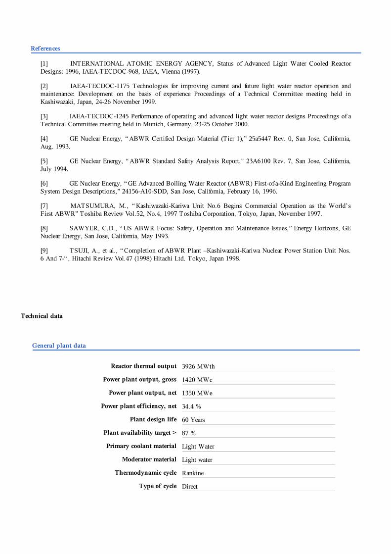
Reactor thermal output 3926 MWth
Power plant output, gross 1420 MWe
Power plant output, net 1350 MWe
Power plant efficiency, net 34.4 %
Plant design life 60 Years
Plant availability target > 87 %
Primary coolant material Light Water
Moderator material Light water
Thermodynamic cycle Rankine
Type of cycle Direct

Safety goals
Core damage frequency < 10E-5 /Reactor-Year
Large early release frequency < 10E-6 /Reactor-Year
Occupational radiation exposure < 1.0 Person-Sv/RY
Nuclear steam supply system
Steam flow rate at nominal conditions 2122 Kg/s
Steam pressure 7.07 MPa(a)
Steam temperature 287.8 °C
Feedwater flow rate at nominal conditions 2118 Kg/s
Feedwater temperature 215.6 °C
Reactor coolant system
Primary coolant flow rate 14502 Kg/s
Reactor operating pressure 7.07 MPa(a)
Core coolant inlet temperature 278 °C
Core coolant outlet temperature 288 °C
Mean temperature rise across core 10 °C
Reactor core
Active core height 3.81 m
Equivalent core diameter 5.163 m
Average linear heat rate 13.3 KW/m
Average fuel power density 25.0 KW/KgU
Average core power density 49.2 MW/m3
Fuel material Sintered UO2
Outer diameter of fuel rods 10.3 mm
Rod array of a fuel assembly 10x10
Lattice geometry Square
Number of fuel assemblies 872
Enrichment of reload fuel at equilibrium core 4 Weight %
Fuel cycle length 24 Months
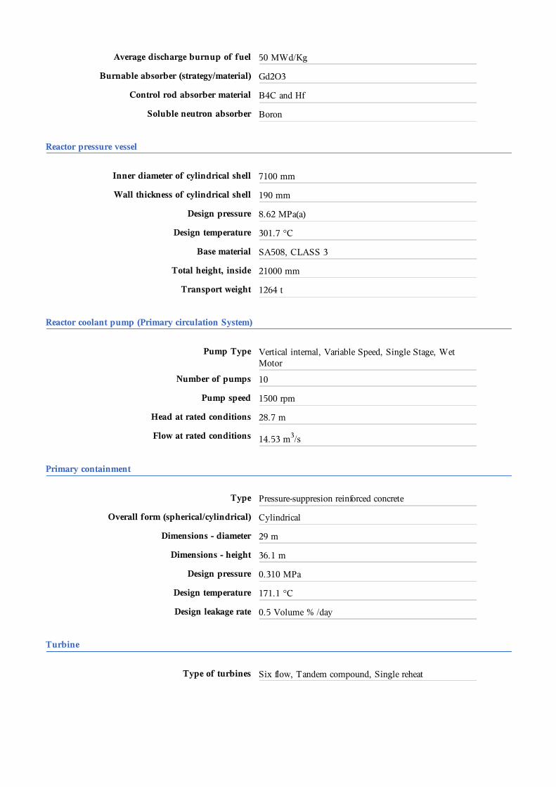
Average discharge burnup of fuel 50 MWd/Kg
Burnable absorber (strategy/material) Gd2O3
Control rod absorber material B4C and Hf
Soluble neutron absorber Boron
Reactor pressure vessel
Inner diameter of cylindrical shell 7100 mm
Wall thickness of cylindrical shell 190 mm
Design pressure 8.62 MPa(a)
Design temperature 301.7 °C
Base material SA508, CLASS 3
Total height, inside 21000 mm
Transport weight 1264 t
Reactor coolant pump (Primary circulation System)
Pump Type Vertical internal, Variable Speed, Single Stage, WetMotor
Number of pumps 10
Pump speed 1500 rpm
Head at rated conditions 28.7 m
Flow at rated conditions 14.53 m3/s
Primary containment
Type Pressure-suppresion reinforced concrete
Overall form (spherical/cylindrical) Cylindrical
Dimensions - diameter 29 m
Dimensions - height 36.1 m
Design pressure 0.310 MPa
Design temperature 171.1 °C
Design leakage rate 0.5 Volume % /day
Turbine
Type of turbines Six flow, Tandem compound, Single reheat

Number of turbine sections per unit (e.g.HP/MP/LP)
1/0/3
Turbine speed 1800 rpm
HP turbine inlet pressure 6.792 MPa(a)
HP turbine inlet temperature 283.7 °C
Generator
Type Three-phase, turbo generator
Rated power 1580 MVA
Active power 1420 MW
Voltage 27 kV
Frequency 60 Hz
Total generator mass including exciter 730 t
Condenser
Type Shell type
Condenser pressure 11.75 kPa
Feedwater pumps
Number 3
Pump speed 5000 rpm
Head at rated conditions 60 m
Flow at rated conditions 1.0 m3/s