ac-215 installation manual -...
TRANSCRIPT
2012
October
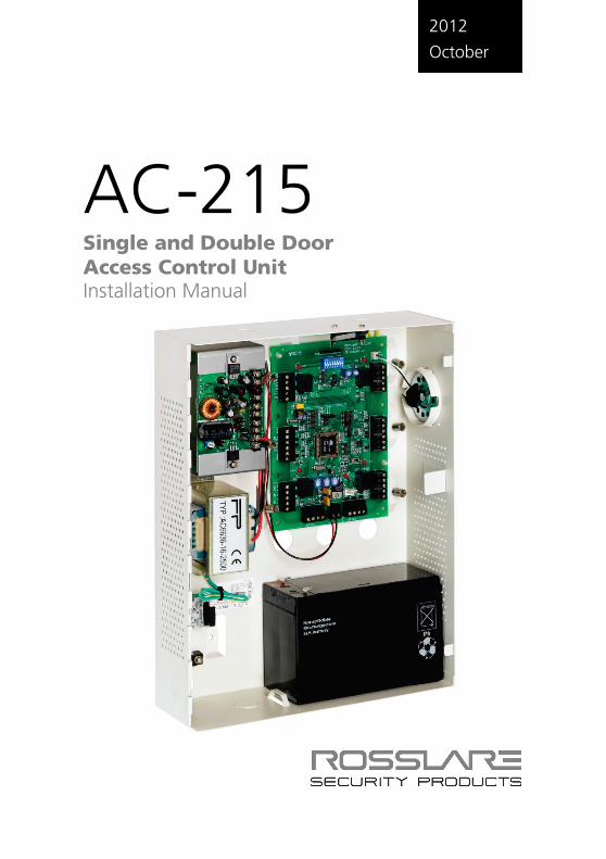
AC-215 Single and Double Door Access Control Unit Installation Manual

Copyright © 2012 by Rosslare. All rights reserved. This manual and the information contained herein are proprietary to REL, RSP Inc. and/or their related companies and/or subsidiaries’ (hereafter:”ROSSLARE”). Only ROSSLARE and its customers have the right to use the information.
No part of this manual may be re-produced or transmitted in any form or by any means, electronic or mechanical, for any purpose, without the express written permission of ROSSLARE.
ROSSLARE owns patents and patent applications, trademarks, copyrights, or other intellectual property rights covering the subject matter in this manual.
TEXTS, IMAGES, AND ILLUSTRATIONS INCLUDING THEIR ARRANGEMENT IN THIS DOCUMENT ARE SUBJECT TO THE PROTECTION OF COPYRIGHT LAWS AND OTHER LEGAL RIGHTS WORLDWIDE. THEIR USE, REPRODUCTION, AND TRANSMITTAL TO THIRD PARTIES WITHOUT EXPRESS WRITTEN PERMISSION MAY RESULT IN LEGAL PROCEEDINGS.
The furnishing of this manual to any party does not give that party or any third party any license to these patents, trademarks, copyrights or other intellectual property rights, except as expressly provided in any written agreement of ROSSLARE.
ROSSLARE reserves the right to revise and change this document at any time, without being obliged to announce such revisions or changes beforehand or after the fact.
Table of Contents
AC-215 Installation Manual iii
Table of Contents 1. Introduction to AC-215 ACU ............................................. 9 1.1 Main Features ................................................................................... 11 1.1.1 AC-215 ..................................................................................................... 11 1.1.2 System ...................................................................................................... 11 1.1.3 AC-215 Single and Double Door Access ..................................................... 11 1.2 Software ........................................................................................... 12
2. Technical Specifications ................................................. 13 2.1 Electrical Specifications ..................................................................... 13 2.1.1 Main Unit .................................................................................................. 13 2.1.2 Outputs .................................................................................................... 13 2.1.3 Inputs ....................................................................................................... 13 2.1.4 Indicators and Annunciators....................................................................... 13 2.1.5 Environmental Specifications ...................................................................... 13 2.1.6 Mechanical Specifications .......................................................................... 13
3. Inputs and Outputs ......................................................... 14 3.1 Inputs ............................................................................................... 14 3.1.1 Release to Exit Button (REX) ....................................................................... 14 3.1.2 Door Monitor ............................................................................................ 14 3.1.3 Tamper ..................................................................................................... 15 3.1.4 General ..................................................................................................... 15 3.1.5 Outputs .................................................................................................... 15 3.1.6 Door Lock ................................................................................................. 15 3.1.7 Door Alarm ............................................................................................... 15 3.1.8 Auxiliary .................................................................................................... 16 3.1.9 General ..................................................................................................... 16 3.1.10 Card Readers ............................................................................................. 16 3.1.11 Keypad ..................................................................................................... 17
4. DIP Switch Settings Configuration ............................... 18 4.1 ACU Baud Rate ................................................................................. 18 4.2 ACU Type ......................................................................................... 19
Table of Contents
iv AC-215 Installation Manual
4.2.1 Single Door Controller ............................................................................... 19 4.2.2 Double Door Controller ............................................................................. 19 4.3 ACU Addressing ............................................................................... 20
5. Communications ............................................................. 22 5.1 Serial Connection ............................................................................. 22 5.1.1 RS-232 Connection ................................................................................... 22 5.1.2 RS-485 Connection to the PC .................................................................... 22 5.1.3 Daisy Chain ............................................................................................... 23 5.1.4 Termination Resistors ................................................................................. 23 5.2 Modem ............................................................................................ 23 5.3 Communication through the Local Area Network (LAN) .................... 24
6. Wiring ............................................................................... 25 6.1 Inputs ............................................................................................... 25 6.2 Outputs ............................................................................................ 25 6.2.1 Power Supply ............................................................................................ 26 6.3 AC-215 Access Control Panel Diagram .............................................. 27 6.4 Reader .............................................................................................. 28
7. Accessories (Proximity Readers) ................................... 29 7.1 AY-C09, AY-D09 PIN Readers ........................................................... 29 7.2 AY-C11 / AY-D11 Prox Readers with Bell........................................... 29 7.3 AY-C11 / AY-D11 Prox Readers ......................................................... 30 7.4 AY-H12, AY-J12, AY-K12, AY-L12, AY-M12 Prox Readers ................. 30 7.5 AY-C19 / AY-D19 PIN & Prox Readers ............................................... 31 7.6 AY-L23 RF Reader ............................................................................. 31
A. Connecting between MD-N32 and AC-215 ................... 32 A.1 Hardware Requirements.................................................................... 32 A.2 Topics ............................................................................................... 32 A.3 Connections – PC Side ...................................................................... 32 A.4 Connections – AC-215 Panel Side ..................................................... 32 A.5 MD-N32 Configuration with AxTrax™ AS-525 .................................. 32
Table of Contents
AC-215 Installation Manual v
B. Connecting between MD-N33 and AC-215 ................... 36 B.1 Hardware Requirements.................................................................... 36 B.2 Topics ............................................................................................... 36 B.3 Connections – PC Side ...................................................................... 36 B.4 Connections – AC-215 Panel Side ..................................................... 36 B.5 MD-N33 Configuration with AxTrax™ AS-525 .................................. 37 B.6 PC modem – configuration and initialization ..................................... 37 B.7 Remote modem – configuration and initialization .............................. 39 B.8 Remote Modem Status ..................................................................... 40 B.9 Restoring factory default configuration ............................................. 41
C. Power Supply Specifications ......................................... 42
D. Limited Warranty ............................................................ 43
List of Figures
vi AC-215 Installation Manual
List of Figures Figure 1: AxTrax™ AS-525 and AC-215 System ............................................ 10 Figure 2: Remote Site Modem Configuration ................................................ 23 Figure 3: MD-N32 Configuration Connecting a Single Panel ......................... 24 Figure 4: Connecting Multiple Access Control Panels with MD-N32 .............. 24 Figure 5: Wiring Four AC-215 Inputs ............................................................ 25 Figure 6: Door Lock – Fail Closed .................................................................. 26 Figure 7: Door Lock – Fail Open .................................................................... 26 Figure 8: AC-215 Wiring to Power Supply ..................................................... 27 Figure 9: AC-215 Wiring Communications .................................................... 27 Figure 10: Reader Cable Coloring ................................................................. 28

List of Tables
AC-215 Installation Manual vii
List of Tables Table 1: DIP Switches and their Functions ..................................................... 18 Table 2: Switch Baud Rates ........................................................................... 18 Table 3: Available Panel Addresses ............................................................... 20 Table 4: RS-232 Connection ......................................................................... 22

Notice and Disclaimer
viii AC-215 Installation Manual
Notice and Disclaimer This manual’s sole purpose is to assist installers and/or users in the safe and efficient installation and usage of the system and/or product, and/or software described herein.
BEFORE ATTEMPTING TO INSTALL AND/OR USE THE SYSTEM, THE INSTALLER AND
THE USER MUST READ THIS MANUAL AND BECOME FAMILIAR WITH ALL SAFETY
REQUIREMENTS AND OPERATING PROCEDURES. The system must not be used for purposes other than those for which it
was designed.
The use of the software associated with the system and/or product, if applicable, is subject to the terms of the license provided as part of the purchase documents.
ROSSLARE ENTERPRISES LIMITED and/or its related companies and/or subsidiaries’ (hereafter:"ROSSLARE") exclusive warranty and liability is limited to the warranty and liability statement provided in an appendix at the end of this document.
This manual describes the maximum configuration of the system with the maximum number of functions, including future options. Therefore, not all functions described in this manual may be available in the specific system and/or product configuration you purchased.
Incorrect operation or installation, or failure of the user to effectively maintain the system, relieves the manufacturer (and seller) from all or any responsibility for consequent noncompliance, damage, or injury.
The text, images and graphics contained in the manual are for the purpose of illustration and reference only.
In no event shall manufacturer be liable for any special, direct, indirect, incidental, consequential, exemplary or punitive damages (including, without limitation, any and all damages from business interruption, loss of profits or revenue, cost of capital or loss of use of any property or capital or injury).
All graphics in this manual are for reference only, some deviation between the image(s) and the actual product may occur.
All wiring diagrams are intended for reference only, the photograph or graphic of the PCB(s) are intended for clearer illustration and understanding of the product and may differ from the actual PCB(s).

Introduction
AC-215 Installation Manual 9
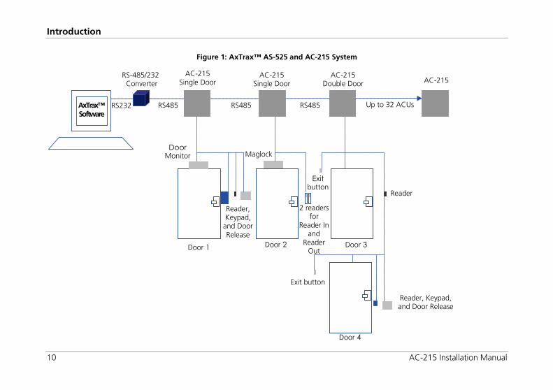
1. Introduction The AC-215 Access Control System and the AxTrax™ AS-525 PC software are a combination that gives full control over the entrances of your premises. The AxTrax™ AS-525 software supports control for both single and double door entrances with which up to 255 AC-215 Access Control Units (ACUs) can be monitored.
The AC-215 employs the latest technology to meet the requirements of the market. It controls one or two doors when used as a standalone controller, and up to 512 doors/256 networks and 5000 users when used as a networked controller using the AxTrax™ AS-525 software.
The AxTrax™ AS-525 software, which is user-friendly and intuitive, defines settings and event logs. A single server, communicating to and from the ACU, can serve unlimited network clients. The system’s database is saved in the server. The database can be set to back up, and can import/export previous configurations. Clients are able to modify the database; for example, define new employees and/or their access permissions.
AxTrax™ AS-525 can run under Windows 98, 2000, NT or XP operating systems.
Figure 1 is an example of how the AxTrax™ AS-525 and AC-215 system can be set up.
Introduction
10 AC-215 Installation Manual
Figure 1: AxTrax™ AS-525 and AC-215 System
AxTrax™ Software
RS-485/232 Converter
AC-215 Single Door
Up to 32 ACUs
AC-215 AC-215
Single Door AC-215
Double Door
RS485 RS232 RS485 RS485
Door Monitor
Door 2
Maglock
Exit button
Reader
Door 4
Exit button
Reader, Keypad, and Door Release
2 readers for
Reader In and
Reader Out
Door 3 Door 1
Reader, Keypad,
and Door Release
Introduction
AC-215 Installation Manual 11
1.1 Main Features
1.1.1 AC-215
Two In/Out readers
Four inputs
Four outputs
Optional secure mode that requires card and PIN entry
Antipassback real and time with forgive feature
Up to 4 different site codes
Automatic operation by time zone for every output
Optional first person delay before automatic door unlocking
Optional expanded lock operation time
Activated auxiliary output by reader transactions or authorized users
Door and panel alarms – door forced , door held open, door held open alert and tamper alarm
Programmable relock when opening/closing doors
Man trap door in double door configuration
Built-in sounder generator for chime, bell and siren signals
1.1.2 System
Up to 256 access control units
Up to 256 networks (with one controller per network)
Up to 32 ACU in every network (64 doors in every network)
Up to 5000 users with rights (up to 25000 users recorded)
5000 log events
64 holidays (copied from MS Outlook – option)
32 time zones
128 access groups
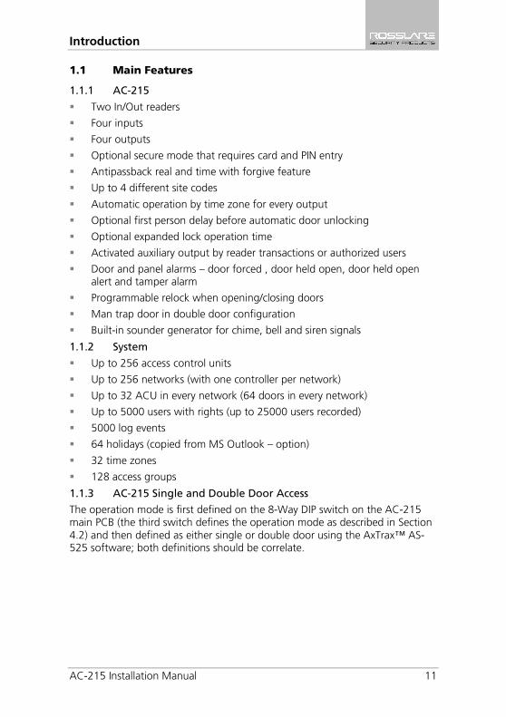
1.1.3 AC-215 Single and Double Door Access
The operation mode is first defined on the 8-Way DIP switch on the AC-215 main PCB (the third switch defines the operation mode as described in Section 4.2) and then defined as either single or double door using the AxTrax™ AS-525 software; both definitions should be correlate.
Introduction
12 AC-215 Installation Manual
1.1.3.1 Single Door Controller
This access type has two readers – In or Out
Outputs Inputs Door lock strike Release to exit
Auxiliary output Door monitor input
Alarm output Tamper input
General purpose output General purpose input
1.1.3.2 Double Door Controller
This access type has two readers – In or Out
Outputs Inputs Door 1 lock strike Release to exit door1
Door 1 alarm output Door 1 monitor input
Door 2 lock strike Release to exit door 2
Door 2 alarm output Door 2 monitor input
1.2 Software
The AxTrax™ AS-525 software is user-friendly and intuitive. Its graphic interface is used to define settings, which are downloaded to the ACU and event logs which are uploaded to the PC to generate reports. A single server, which communicates to and from the ACU, can serve unlimited network clients.
The system’s database is saved in the server. The database can be set to backup and can import/export previous configurations. Clients are able to modify the database, for example, define new employees and their access permissions.
The software enables features to be added as and when they are required. The modular software enables the user interface to be as powerful and strong as required and yet remains simple to use. The software can be set for automatic backup on a periodic basis.
AxTrax™ AS-525 can be run on Windows 98, 2000, NT and XP.
For UL installations, the installer must configure the system as fail-safe to comply with NFPA (National Fire Protection Association) regulations.
Technical Specifications
AC-215 Installation Manual 13
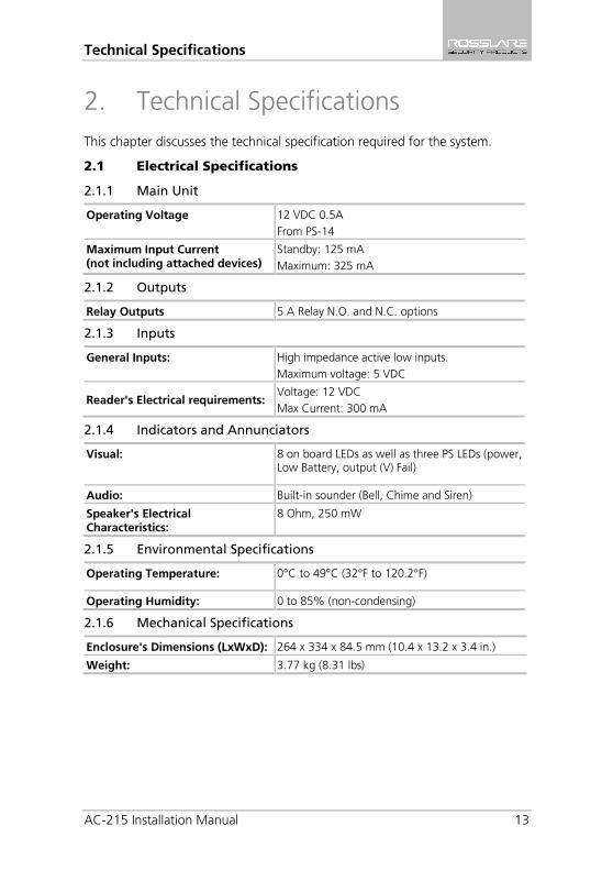
2. Technical Specifications This chapter discusses the technical specification required for the system.
2.1 Electrical Specifications
2.1.1 Main Unit
Operating Voltage 12 VDC 0.5A From PS-14
Maximum Input Current (not including attached devices)
Standby: 125 mA Maximum: 325 mA
2.1.2 Outputs
Relay Outputs 5 A Relay N.O. and N.C. options
2.1.3 Inputs
General Inputs: High impedance active low inputs. Maximum voltage: 5 VDC
Reader's Electrical requirements: Voltage: 12 VDC Max Current: 300 mA
2.1.4 Indicators and Annunciators
Visual: 8 on board LEDs as well as three PS LEDs (power, Low Battery, output (V) Fail)
Audio: Built-in sounder (Bell, Chime and Siren)
Speaker's Electrical Characteristics:
8 Ohm, 250 mW
2.1.5 Environmental Specifications
Operating Temperature: 0°C to 49°C (32°F to 120.2°F)
Operating Humidity: 0 to 85% (non-condensing)
2.1.6 Mechanical Specifications
Enclosure's Dimensions (LxWxD): 264 x 334 x 84.5 mm (10.4 x 13.2 x 3.4 in.)
Weight: 3.77 kg (8.31 lbs)
Inputs and Outputs
14 AC-215 Installation Manual
3. Inputs and Outputs This chapter discusses the AC-215 ACU input and output requirements.
3.1 Inputs
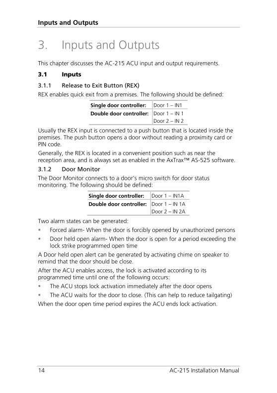
3.1.1 Release to Exit Button (REX)
REX enables quick exit from a premises. The following should be defined:
Single door controller: Door 1 – IN1
Double door controller: Door 1 – IN 1
Door 2 – IN 2
Usually the REX input is connected to a push button that is located inside the premises. The push button opens a door without reading a proximity card or PIN code.
Generally, the REX is located in a convenient position such as near the reception area, and is always set as enabled in the AxTrax™ AS-525 software.
3.1.2 Door Monitor
The Door Monitor connects to a door’s micro switch for door status monitoring. The following should be defined:
Single door controller: Door 1 – IN1A
Double door controller: Door 1 – IN 1A Door 2 – IN 2A
Two alarm states can be generated:
Forced alarm- When the door is forcibly opened by unauthorized persons
Door held open alarm- When the door is open for a period exceeding the lock strike programmed open time
A Door held open alert can be generated by activating chime on speaker to remind that the door should be close.
After the ACU enables access, the lock is activated according to its programmed time until one of the following occurs:
The ACU stops lock activation immediately after the door opens
The ACU waits for the door to close. (This can help to reduce tailgating)
When the door open time period expires the ACU ends lock activation.
Inputs and Outputs
AC-215 Installation Manual 15
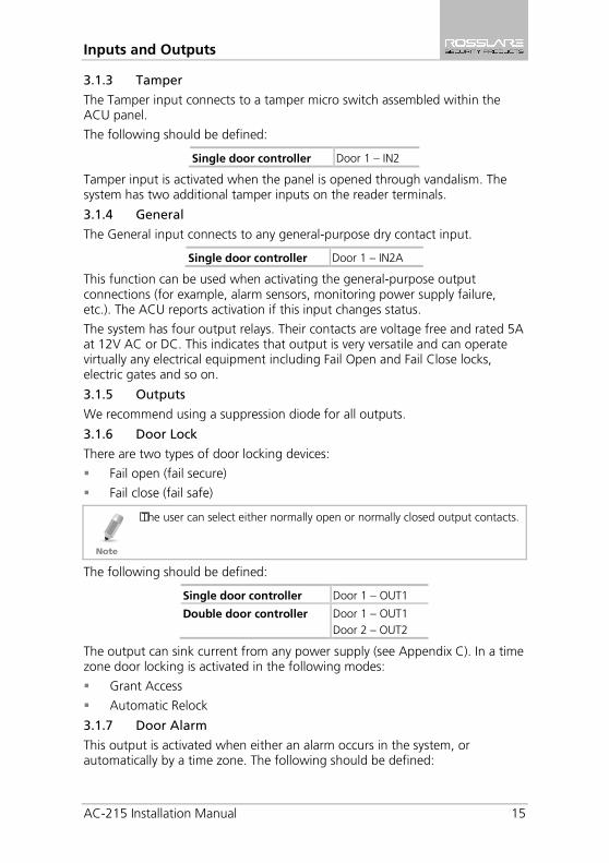
3.1.3 Tamper
The Tamper input connects to a tamper micro switch assembled within the ACU panel.
The following should be defined:
Single door controller Door 1 – IN2
Tamper input is activated when the panel is opened through vandalism. The system has two additional tamper inputs on the reader terminals.
3.1.4 General
The General input connects to any general-purpose dry contact input.
Single door controller Door 1 – IN2A
This function can be used when activating the general-purpose output connections (for example, alarm sensors, monitoring power supply failure, etc.). The ACU reports activation if this input changes status.
The system has four output relays. Their contacts are voltage free and rated 5A at 12V AC or DC. This indicates that output is very versatile and can operate virtually any electrical equipment including Fail Open and Fail Close locks, electric gates and so on.
3.1.5 Outputs
We recommend using a suppression diode for all outputs.
3.1.6 Door Lock
There are two types of door locking devices:
Fail open (fail secure)
Fail close (fail safe)
The user can select either normally open or normally closed output contacts.
The following should be defined:
Single door controller Door 1 – OUT1
Double door controller Door 1 – OUT1 Door 2 – OUT2
The output can sink current from any power supply (see Appendix C). In a time zone door locking is activated in the following modes:
Grant Access
Automatic Relock
3.1.7 Door Alarm
This output is activated when either an alarm occurs in the system, or automatically by a time zone. The following should be defined:
Inputs and Outputs
16 AC-215 Installation Manual
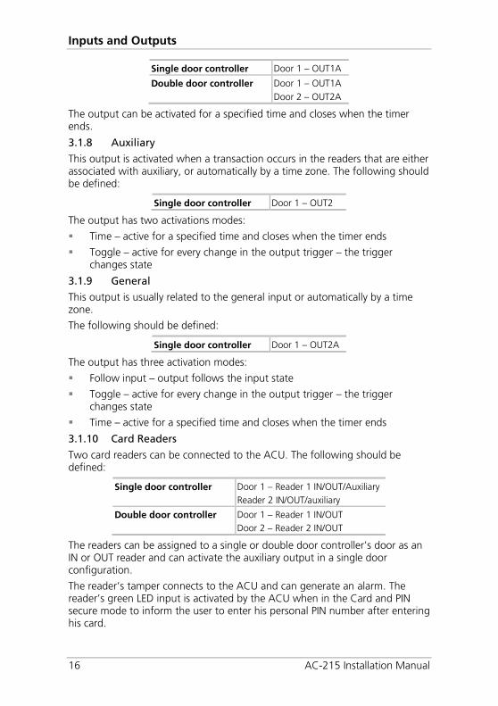
Single door controller Door 1 – OUT1A
Double door controller Door 1 – OUT1A Door 2 – OUT2A
The output can be activated for a specified time and closes when the timer ends.
3.1.8 Auxiliary
This output is activated when a transaction occurs in the readers that are either associated with auxiliary, or automatically by a time zone. The following should be defined:
Single door controller Door 1 – OUT2
The output has two activations modes:
Time – active for a specified time and closes when the timer ends
Toggle – active for every change in the output trigger – the trigger changes state
3.1.9 General
This output is usually related to the general input or automatically by a time zone.
The following should be defined:
Single door controller Door 1 – OUT2A
The output has three activation modes:
Follow input – output follows the input state
Toggle – active for every change in the output trigger – the trigger changes state
Time – active for a specified time and closes when the timer ends
3.1.10 Card Readers
Two card readers can be connected to the ACU. The following should be defined:
Single door controller Door 1 – Reader 1 IN/OUT/Auxiliary Reader 2 IN/OUT/auxiliary
Double door controller Door 1 – Reader 1 IN/OUT Door 2 – Reader 2 IN/OUT
The readers can be assigned to a single or double door controller’s door as an IN or OUT reader and can activate the auxiliary output in a single door configuration.
The reader’s tamper connects to the ACU and can generate an alarm. The reader’s green LED input is activated by the ACU when in the Card and PIN secure mode to inform the user to enter his personal PIN number after entering his card.

Inputs and Outputs
AC-215 Installation Manual 17
3.1.11 Keypad
Two keypads can be alternatively connected to the ACU on Reader1 and Reader2 terminals. The following should be defined:
Single door controller Door 1 Keypad – Reader 1 IN/OUT Keypad – Reader 2 IN/OUT
Double door controller Door 1 Keypad – Reader 1 IN/OUT Door 2 Keypad – Reader 2 IN/OUT
The keypad type must be a Rosslare format keypad.
A keypad has to be connected for any reader mode that requires PIN code entries, such as Card or PIN, PIN only or Card and PIN (Secured mode).
DIP Switch Settings Configuration
18 AC-215 Installation Manual
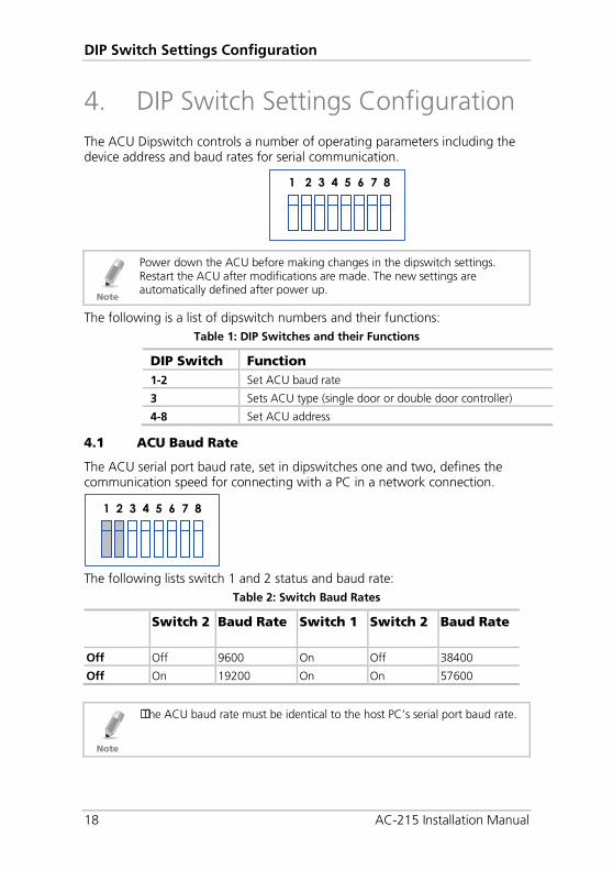
4. DIP Switch Settings Configuration The ACU Dipswitch controls a number of operating parameters including the device address and baud rates for serial communication.
Power down the ACU before making changes in the dipswitch settings. Restart the ACU after modifications are made. The new settings are automatically defined after power up.
The following is a list of dipswitch numbers and their functions: Table 1: DIP Switches and their Functions
DIP Switch Function 1-2 Set ACU baud rate
3 Sets ACU type (single door or double door controller)
4-8 Set ACU address
4.1 ACU Baud Rate
The ACU serial port baud rate, set in dipswitches one and two, defines the communication speed for connecting with a PC in a network connection.
The following lists switch 1 and 2 status and baud rate:
Table 2: Switch Baud Rates
Switch 2 Baud Rate Switch 1 Switch 2 Baud Rate
Off Off 9600 On Off 38400
Off On 19200 On On 57600
The ACU baud rate must be identical to the host PC’s serial port baud rate.
1 2 3 4 5 6 7 8
1 2 3 4 5 6 7 8
DIP Switch Settings Configuration
AC-215 Installation Manual 19
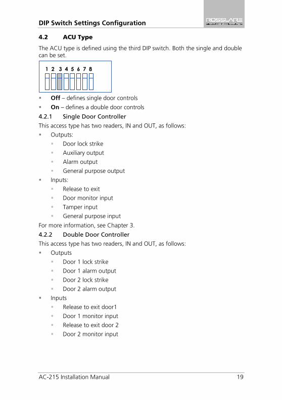
4.2 ACU Type
The ACU type is defined using the third DIP switch. Both the single and double can be set.
Off – defines single door controls
On – defines a double door controls
4.2.1 Single Door Controller
This access type has two readers, IN and OUT, as follows:
Outputs:
Door lock strike
Auxiliary output
Alarm output
General purpose output
Inputs:
Release to exit
Door monitor input
Tamper input
General purpose input
For more information, see Chapter 3.
4.2.2 Double Door Controller
This access type has two readers, IN and OUT, as follows:
Outputs
Door 1 lock strike
Door 1 alarm output
Door 2 lock strike
Door 2 alarm output
Inputs
Release to exit door1
Door 1 monitor input
Release to exit door 2
Door 2 monitor input
1 2 3 4 5 6 7 8
DIP Switch Settings Configuration
20 AC-215 Installation Manual
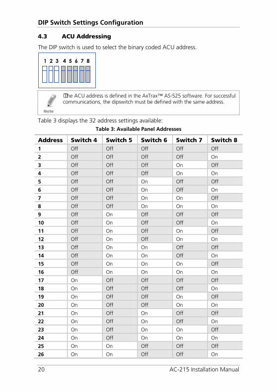
4.3 ACU Addressing
The DIP switch is used to select the binary coded ACU address.
The ACU address is defined in the AxTrax™ AS-525 software. For successful communications, the dipswitch must be defined with the same address.
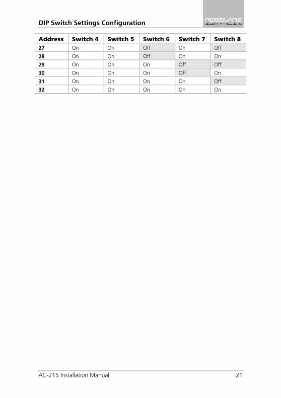
Table 3 displays the 32 address settings available: Table 3: Available Panel Addresses
Address Switch 4 Switch 5 Switch 6 Switch 7 Switch 8 1 Off Off Off Off Off
2 Off Off Off Off On
3 Off Off Off On Off
4 Off Off Off On On
5 Off Off On Off Off
6 Off Off On Off On
7 Off Off On On Off
8 Off Off On On On
9 Off On Off Off Off
10 Off On Off Off On
11 Off On Off On Off
12 Off On Off On On
13 Off On On Off Off
14 Off On On Off On
15 Off On On On Off
16 Off On On On On
17 On Off Off Off Off
18 On Off Off Off On
19 On Off Off On Off
20 On Off Off On On
21 On Off On Off Off
22 On Off On Off On
23 On Off On On Off
24 On Off On On On
25 On On Off Off Off
26 On On Off Off On
1 2 3 4 5 6 7 8
DIP Switch Settings Configuration
AC-215 Installation Manual 21
Address Switch 4 Switch 5 Switch 6 Switch 7 Switch 8 27 On On Off On Off
28 On On Off On On
29 On On On Off Off
30 On On On Off On
31 On On On On Off
32 On On On On On
Communications
22 AC-215 Installation Manual
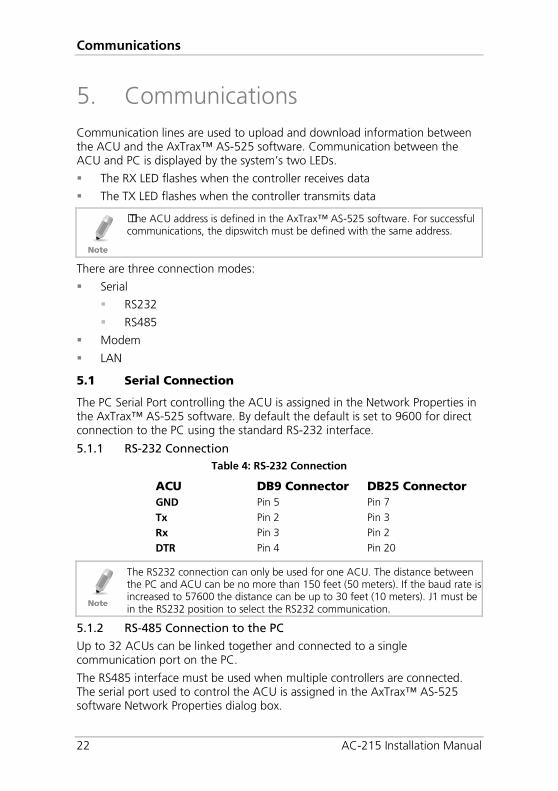
5. Communications Communication lines are used to upload and download information between the ACU and the AxTrax™ AS-525 software. Communication between the ACU and PC is displayed by the system’s two LEDs.
The RX LED flashes when the controller receives data
The TX LED flashes when the controller transmits data
The ACU address is defined in the AxTrax™ AS-525 software. For successful communications, the dipswitch must be defined with the same address.
There are three connection modes:
Serial
RS232
RS485
Modem
LAN
5.1 Serial Connection
The PC Serial Port controlling the ACU is assigned in the Network Properties in the AxTrax™ AS-525 software. By default the default is set to 9600 for direct connection to the PC using the standard RS-232 interface.
5.1.1 RS-232 Connection Table 4: RS-232 Connection
ACU DB9 Connector DB25 Connector GND Pin 5 Pin 7 Tx Pin 2 Pin 3 Rx Pin 3 Pin 2 DTR Pin 4 Pin 20
The RS232 connection can only be used for one ACU. The distance between the PC and ACU can be no more than 150 feet (50 meters). If the baud rate is increased to 57600 the distance can be up to 30 feet (10 meters). J1 must be in the RS232 position to select the RS232 communication.
5.1.2 RS-485 Connection to the PC
Up to 32 ACUs can be linked together and connected to a single communication port on the PC.
The RS485 interface must be used when multiple controllers are connected. The serial port used to control the ACU is assigned in the AxTrax™ AS-525 software Network Properties dialog box.
Communications
AC-215 Installation Manual 23
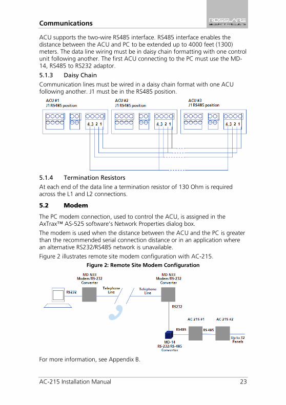
ACU supports the two-wire RS485 interface. RS485 interface enables the distance between the ACU and PC to be extended up to 4000 feet (1300) meters. The data line wiring must be in daisy chain formatting with one control unit following another. The first ACU connecting to the PC must use the MD-14, RS485 to RS232 adaptor.
5.1.3 Daisy Chain
Communication lines must be wired in a daisy chain format with one ACU following another. J1 must be in the RS485 position.
5.1.4 Termination Resistors
At each end of the data line a termination resistor of 130 Ohm is required across the L1 and L2 connections.
5.2 Modem
The PC modem connection, used to control the ACU, is assigned in the AxTrax™ AS-525 software’s Network Properties dialog box.
The modem is used when the distance between the ACU and the PC is greater than the recommended serial connection distance or in an application where an alternative RS232/RS485 network is unavailable.
Figure 2 illustrates remote site modem configuration with AC-215. Figure 2: Remote Site Modem Configuration
For more information, see Appendix B.

Communications
24 AC-215 Installation Manual
5.3 Communication through the Local Area Network (LAN)
The TCP/IP connection, used to control the ACU, is assigned in the AxTrax™ AS-525 software’s Network Properties dialog box.
The PC running the AxTrax™ AS-525 software can communicate with the ACU through the LAN card inside the PC. The ACU connects to the LAN using Rosslare MD-N32, TCP/IP to RS232 gateway converter. MD-N32 can be connected in any legal network address in the Local Area Network.
The following type of connection is used when a LAN network already exists and therefore the long RS485 network is not required. This schematic illustrates the connection of a single AC-215 to the PC using the LAN network.
MD-N32 must be first configured by Rosslare's Netconfig software. The setting is stored in a non-volatile memory in the MD-N32.
Figure 3: MD-N32 Configuration Connecting a Single Panel
Multiple ACUs can be connected by adding an RS485 converter (MD-14) between the RS485 ACUs network and MD-N32 converter.
Figure 4: Connecting Multiple Access Control Panels with MD-N32
For more information, see Appendix A.
Wiring
AC-215 Installation Manual 25
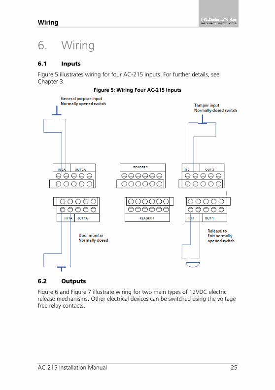
6. Wiring 6.1 Inputs
Figure 5 illustrates wiring for four AC-215 inputs. For further details, see Chapter 3.
Figure 5: Wiring Four AC-215 Inputs
6.2 Outputs
Figure 6 and Figure 7 illustrate wiring for two main types of 12VDC electric release mechanisms. Other electrical devices can be switched using the voltage free relay contacts.
Wiring
26 AC-215 Installation Manual
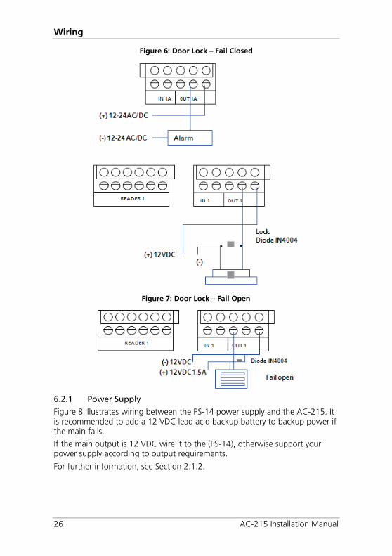
Figure 6: Door Lock – Fail Closed
Figure 7: Door Lock – Fail Open
6.2.1 Power Supply
Figure 8 illustrates wiring between the PS-14 power supply and the AC-215. It is recommended to add a 12 VDC lead acid backup battery to backup power if the main fails.
If the main output is 12 VDC wire it to the (PS-14), otherwise support your power supply according to output requirements.
For further information, see Section 2.1.2.
Wiring
AC-215 Installation Manual 27
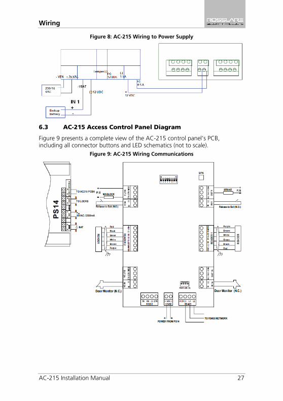
Figure 8: AC-215 Wiring to Power Supply
6.3 AC-215 Access Control Panel Diagram
Figure 9 presents a complete view of the AC-215 control panel’s PCB, including all connector buttons and LED schematics (not to scale).
Figure 9: AC-215 Wiring Communications
Wiring
28 AC-215 Installation Manual
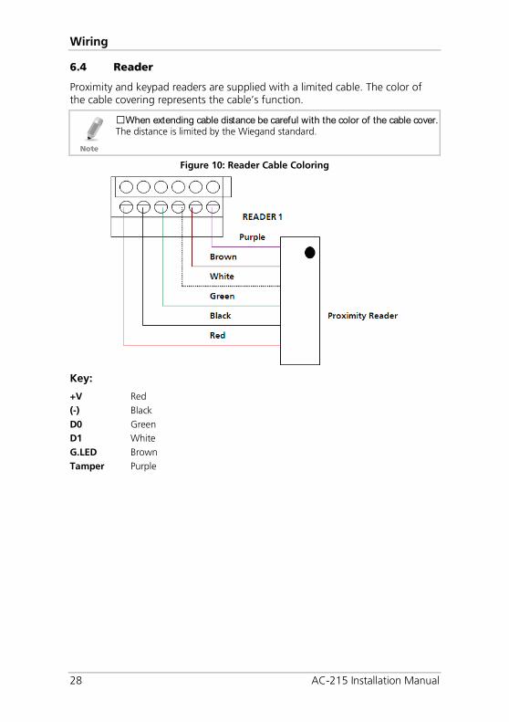
6.4 Reader
Proximity and keypad readers are supplied with a limited cable. The color of the cable covering represents the cable’s function.
When extending cable distance be careful with the color of the cable cover. The distance is limited by the Wiegand standard.
Figure 10: Reader Cable Coloring
Key:
+V Red (-) Black D0 Green D1 White G.LED Brown Tamper Purple
Accessories (Proximity Readers)
AC-215 Installation Manual 29
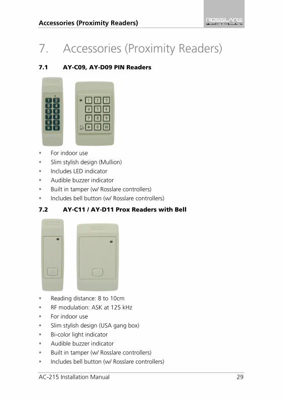
7. Accessories (Proximity Readers) 7.1 AY-C09, AY-D09 PIN Readers
For indoor use
Slim stylish design (Mullion)
Includes LED indicator
Audible buzzer indicator
Built in tamper (w/ Rosslare controllers)
Includes bell button (w/ Rosslare controllers)
7.2 AY-C11 / AY-D11 Prox Readers with Bell
Reading distance: 8 to 10cm
RF modulation: ASK at 125 kHz
For indoor use
Slim stylish design (USA gang box)
Bi-color light indicator
Audible buzzer indicator
Built in tamper (w/ Rosslare controllers)
Includes bell button (w/ Rosslare controllers)
Accessories (Proximity Readers)
30 AC-215 Installation Manual
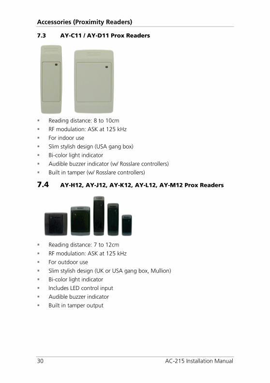
7.3 AY-C11 / AY-D11 Prox Readers
Reading distance: 8 to 10cm
RF modulation: ASK at 125 kHz
For indoor use
Slim stylish design (USA gang box)
Bi-color light indicator
Audible buzzer indicator (w/ Rosslare controllers)
Built in tamper (w/ Rosslare controllers)
7.4 AY-H12, AY-J12, AY-K12, AY-L12, AY-M12 Prox Readers
Reading distance: 7 to 12cm
RF modulation: ASK at 125 kHz
For outdoor use
Slim stylish design (UK or USA gang box, Mullion)
Bi-color light indicator
Includes LED control input
Audible buzzer indicator
Built in tamper output
Accessories (Proximity Readers)
AC-215 Installation Manual 31
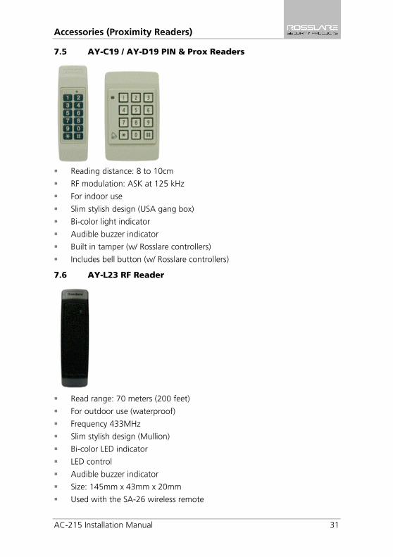
7.5 AY-C19 / AY-D19 PIN & Prox Readers
Reading distance: 8 to 10cm
RF modulation: ASK at 125 kHz
For indoor use
Slim stylish design (USA gang box)
Bi-color light indicator
Audible buzzer indicator
Built in tamper (w/ Rosslare controllers)
Includes bell button (w/ Rosslare controllers)
7.6 AY-L23 RF Reader
Read range: 70 meters (200 feet)
For outdoor use (waterproof)
Frequency 433MHz
Slim stylish design (Mullion)
Bi-color LED indicator
LED control
Audible buzzer indicator
Size: 145mm x 43mm x 20mm
Used with the SA-26 wireless remote
Connecting between MD-N32 and AC-215
32 AC-215 Installation Manual
A. Connecting between MD-N32 and AC-215
This manual is written as step by step instruction. It is very important to follow the right order.
A.1 Hardware Requirements
Standard LAN cable – RJ45 plugs in both sides.
Rosslare's MD-14 (RS232 to RS485 converter).
Rosslare's MD-N32 (TCP/IP to serial gateway).
Rosslare's AC-215 panel.
A.2 Topics
Before setting, ask your network administrator for one, free IP address and subnet mask, which has to be used here.
The IP addresses shown in the examples below are for illustration purpose only.
A.3 Connections – PC Side
Connect the PC using the internal network card (Mostly in the rear side of the PC) to the LAN network with regular network cable.
(If the PC is already identified and known in the local network, it is already connected and you do not need any further installation).
A.4 Connections – AC-215 Panel Side
1. Connect a 9 VDC adapter to the MD-N32. Check that the power LED (Red) is on.
2. Connect the MD-N32 to the LAN by using a regular network cable through the MD-N32's RJ-45 connector. Check that the link LED (Green) is on.
3. Connect MD-N32's DB9 male jack to MD-14's DB9 female jack with cross serial cable.
4. Connect the AC-215's RS-485 outlet to MD-14 4 wires cable.
5. Make sure that J1 (on the AC-215) is set to RS485 Mode.
6. If the jumper was not set properly, make the change, turn the power of AC-215 off, wait few seconds and turn it on.
A.5 MD-N32 Configuration with AxTrax™ AS-525
1. Add a new network using the AxTrax™ AS-525 software (for more details, see the AxTrax™ user manuals.)
Connecting between MD-N32 and AC-215
AC-215 Installation Manual 33
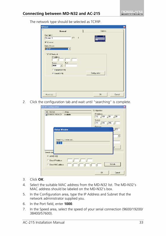
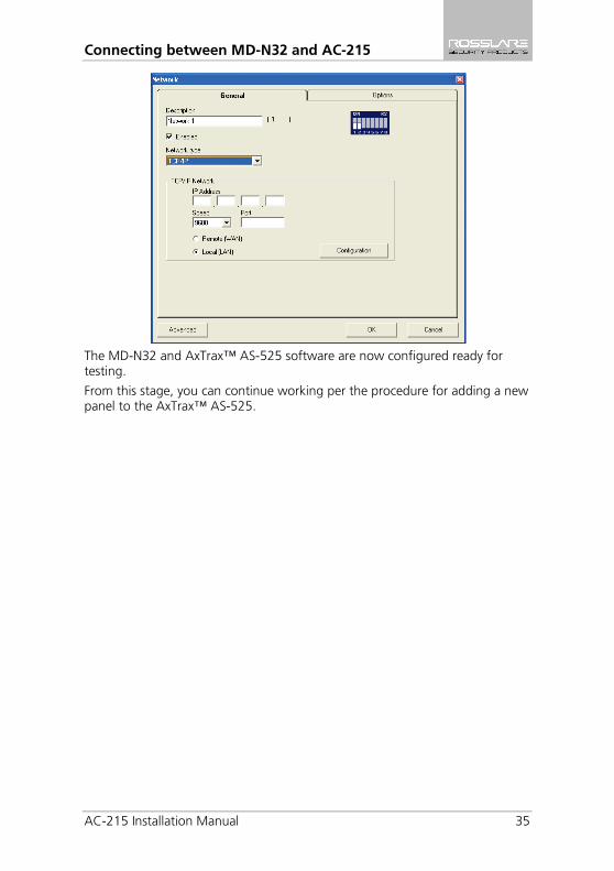
The network type should be selected as TCP/IP.
2. Click the configuration tab and wait until "searching" is complete.
3. Click OK.
4. Select the suitable MAC address from the MD-N32 list. The MD-N32's MAC address should be labeled on the MD-N32's box.
5. In the Configuration area, type the IP Address and Subnet that the network administrator supplied you.
6. In the Port field, enter 1000.
7. In the Speed area, select the speed of your serial connection (9600/19200/ 38400/57600).
Connecting between MD-N32 and AC-215
34 AC-215 Installation Manual
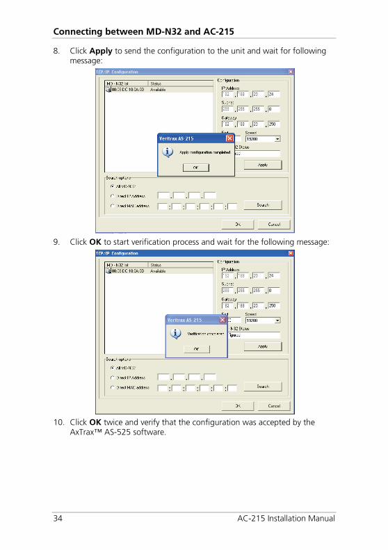
8. Click Apply to send the configuration to the unit and wait for following message:
9. Click OK to start verification process and wait for the following message:
10. Click OK twice and verify that the configuration was accepted by the
AxTrax™ AS-525 software.
Connecting between MD-N32 and AC-215
AC-215 Installation Manual 35
The MD-N32 and AxTrax™ AS-525 software are now configured ready for testing.
From this stage, you can continue working per the procedure for adding a new panel to the AxTrax™ AS-525.
Connecting between MD-N33 and AC-215
36 AC-215 Installation Manual
B. Connecting between MD-N33 and AC-215
This manual is written as step by step instruction. It is very important to follow the right order.
B.1 Hardware Requirements
2 Standard Telephone cables – RJ11 plugs in both sides.
Standard Serial cable D-type 9 pin (Female connectors at both sides)
Rosslare's MD-14 (RS232 to RS485 converter).
2 Rosslare's MD-N33 (Modem to serial gateway).
Rosslare's AC-215 panel.
B.2 Topics
The telephone numbers shown at the examples below are for illustration purpose only.
Before permanent modem installations, the modem that has to be connected to the panel must initialize at PC running the AxTrax™ AS-525 software.
B.3 Connections – PC Side
1. Connect a 9 VDC adapter to the first MD-N33.
2. Make sure that the power LED (Red) is on.
3. Connect the PC, using a free COM port, to the MD-N33 with cross serial cable.
4. Connect the MD-N33's RJ11 jack to telephone line using the telephone cable.
B.4 Connections – AC-215 Panel Side
1. Connect a 9 VDC adapter to the second MD-N33.
2. Make sure that the power LED (Red) is on.
3. Connect the MD-N33's DB11 jack to telephone wall mount using the telephone cable.
4. Connect MD-N33's DB9 female jack to MD-14's DB9 female jack.
5. Connect the AC-215's RS-485 outlet to the MD-14 4-wire cable.
6. Make sure that J1 (on the AC-215) is set to RS-485 Mode.
7. If the jumper was not set properly, make the change, turn the power of AC-215 off, wait few seconds and turn it on.
Connecting between MD-N33 and AC-215
AC-215 Installation Manual 37
B.5 MD-N33 Configuration with AxTrax™ AS-525
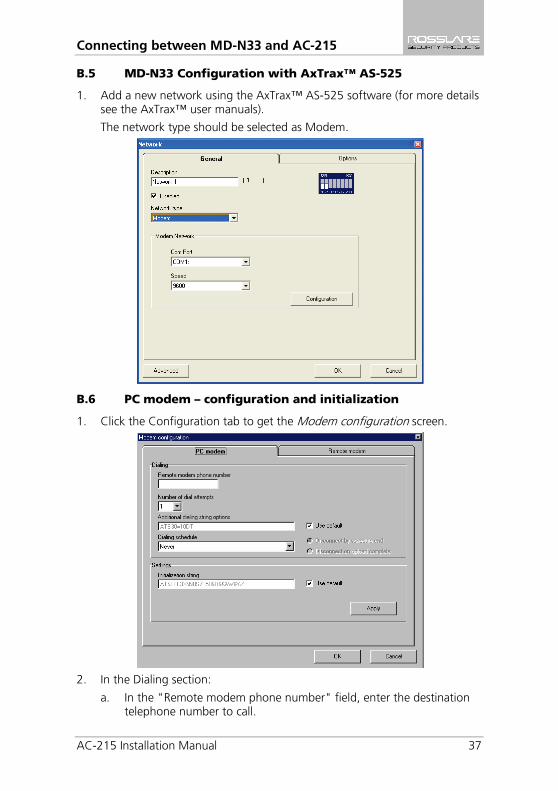
1. Add a new network using the AxTrax™ AS-525 software (for more details see the AxTrax™ user manuals).
The network type should be selected as Modem.
B.6 PC modem – configuration and initialization
1. Click the Configuration tab to get the Modem configuration screen.
2. In the Dialing section:
a. In the "Remote modem phone number" field, enter the destination telephone number to call.
Connecting between MD-N33 and AC-215
38 AC-215 Installation Manual
b. Change the "number of dial attempts" as needed.
c. In the Additional dialing string options field, for most applications, the default dialing string of AS-525 is enough.
The dialing string is displayed in the window.
Adding or editing dialing string is allowed by clearing the "Use default" checkbox and typing the AT command in the dialing string window.
d. In the “Dialing schedule” dropdown, select the proper time zone.
The disconnecting condition can be chosen: "Disconnect by schedule end" or "Disconnect on upload complete". (It is allowed when the selected time zone is different than the default time zones (Always & Never).
3. In the Settings section:
For most applications, the default initialization string of AS-525 is enough.
The initialization string is displayed in the window.
Adding or editing initialization string is allowed by clearing "Use default" and type the AT command in the "Initialization string" window.
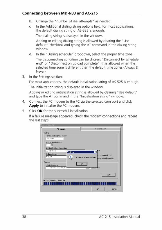
4. Connect the PC modem to the PC via the selected com port and click Apply to initialize the PC modem.
5. Click OK for the successful initialization.
If a failure message appeared, check the modem connections and repeat the last steps.
Connecting between MD-N33 and AC-215
AC-215 Installation Manual 39
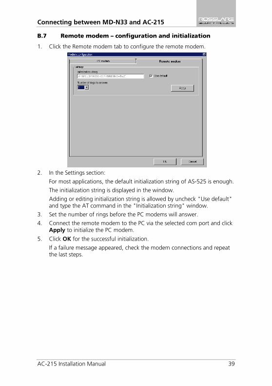
B.7 Remote modem – configuration and initialization
1. Click the Remote modem tab to configure the remote modem.
2. In the Settings section:
For most applications, the default initialization string of AS-525 is enough.
The initialization string is displayed in the window.
Adding or editing initialization string is allowed by uncheck "Use default" and type the AT command in the "Initialization string" window.
3. Set the number of rings before the PC modems will answer.
4. Connect the remote modem to the PC via the selected com port and click Apply to initialize the PC modem.
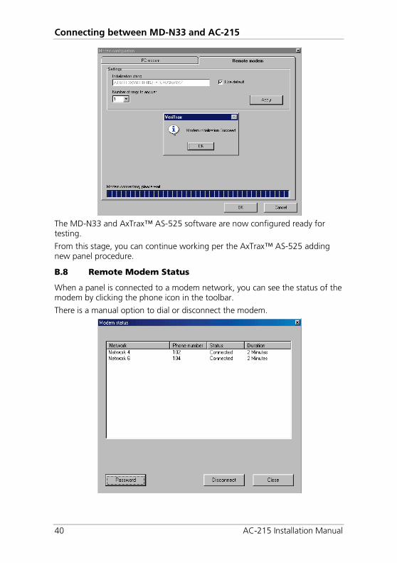
5. Click OK for the successful initialization.
If a failure message appeared, check the modem connections and repeat the last steps.
Connecting between MD-N33 and AC-215
40 AC-215 Installation Manual
The MD-N33 and AxTrax™ AS-525 software are now configured ready for testing.
From this stage, you can continue working per the AxTrax™ AS-525 adding new panel procedure.
B.8 Remote Modem Status
When a panel is connected to a modem network, you can see the status of the modem by clicking the phone icon in the toolbar.
There is a manual option to dial or disconnect the modem.
Connecting between MD-N33 and AC-215
AC-215 Installation Manual 41
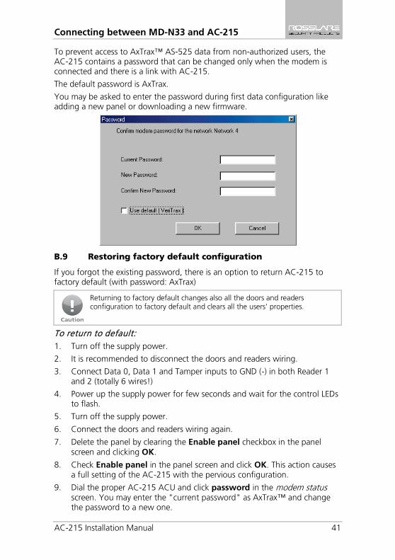
To prevent access to AxTrax™ AS-525 data from non-authorized users, the AC-215 contains a password that can be changed only when the modem is connected and there is a link with AC-215.
The default password is AxTrax.
You may be asked to enter the password during first data configuration like adding a new panel or downloading a new firmware.
B.9 Restoring factory default configuration
If you forgot the existing password, there is an option to return AC-215 to factory default (with password: AxTrax)
Returning to factory default changes also all the doors and readers configuration to factory default and clears all the users' properties.
To return to default: 1. Turn off the supply power.
2. It is recommended to disconnect the doors and readers wiring.
3. Connect Data 0, Data 1 and Tamper inputs to GND (-) in both Reader 1 and 2 (totally 6 wires!)
4. Power up the supply power for few seconds and wait for the control LEDs to flash.
5. Turn off the supply power.
6. Connect the doors and readers wiring again.
7. Delete the panel by clearing the Enable panel checkbox in the panel screen and clicking OK.
8. Check Enable panel in the panel screen and click OK. This action causes a full setting of the AC-215 with the pervious configuration.
9. Dial the proper AC-215 ACU and click password in the modem status screen. You may enter the "current password" as AxTrax™ and change the password to a new one.

Power Supply Specifications
42 AC-215 Installation Manual
C. Power Supply Specifications ACU uses the PS-14 power supply.
Transformer AC Transformer 120/220 VAC, 16 VAC 2.5 A (40 VA), Class 2
(not included)
PS-14 Power Supply Specifications Input Voltage 16 VAC, 2.5 A
From Transformer – Backup Battery Charger
12 VDC, 300 mA
From Transformer – Output Voltage 1
13.8 V
Access control panel – Output Voltage 2
12 VDC, 0.5 A
From ACU (to lock strike) – Output Voltage 3
12 VDC, 1.5 A
Power Supply Indication Tamper Output (open collector) Indicates faulty power
Power LEDs Power In (AC) – Green LED1 Main power
Power Out (DC) – Red LED2 Low voltage
Charger (BAT) – Red LED3 Backup battery low voltage
Limited Warranty
AC-215 Installation Manual 43
D. Limited Warranty ROSSLARE’S TWO-YEAR LIMITED WARRANTY is applicable worldwide. This warranty supersedes any other warranty. ROSSLARE'S TWO-YEAR LIMITED WARRANTY is subject to the following conditions:
WARRANTY
Warranty of ROSSLARE'S products extends to the original purchaser (Customer) of the ROSSLARE product and is not transferable.
PRODUCTS COVERED BY THIS WARRANTY AND DURATION ROSSLARE warrants the AC-215 Single and Double Door Access Control Unit to be free from defects in materials and assembly in the course of normal use and service. The warranty period commences with the date of shipment to the original purchaser and extends for a period of 2 years (24 months).
WARRANTY REMEDY COVERAGE
In the event of a breach of warranty, ROSSLARE will credit Customer with the price of the Product paid by Customer, provided that the warranty claim is delivered to ROSSLARE by the Customer during the warranty period in accordance with the terms of this warranty. Unless otherwise requested by a ROSSLARE representative, return of the failed product(s) is not immediately required.
If ROSSLARE has not contacted the Customer within a sixty (60) day holding period following the delivery of the warranty claim, Customer will not be required to return the failed product(s). All returned Product(s), as may be requested at ROSSLARE’S sole discretion, shall become the property of ROSSLARE.
To exercise the warranty, the user must contact ROSSLARE Enterprises Ltd. to obtain an RMA number after which, the product must be returned to the Manufacturer freight prepaid and insured.
In the event ROSSLARE chooses to perform a product evaluation within the sixty (60) day holding period and no defect is found, a minimum US$ 50.00 or equivalent charge will be applied to each Product for labor required in the evaluation.
ROSSLARE will repair or replace, at its discretion, any product that under normal conditions of use and service proves to be defective in material or workmanship. No charge will be applied for labor or parts with respect to defects covered by this warranty, provided that the work is done by ROSSLARE or a ROSSLARE authorized service center.

Limited Warranty
44 AC-215 Installation Manual
EXCLUSIONS AND LIMITATIONS ROSSLARE shall not be responsible or liable for any damage or loss resulting from the operation or performance of any Product or any systems in which a Product is incorporated. This warranty shall not extend to any ancillary equipment not furnished by ROSSLARE, which is attached to or used in conjunction with a Product, nor to any Product that is used with any ancillary equipment, which is not furnished by ROSSLARE.
This warranty does not cover expenses incurred in the transportation, freight cost to the repair center, removal or reinstallation of the product, whether or not proven defective.
Specifically excluded from this warranty are any failures resulting from Customer's improper testing, operation, installation, or damage resulting from use of the Product in other than its normal and customary manner, or any maintenance, modification, alteration, or adjustment or any type of abuse, neglect, accident, misuse, improper operation, normal wear, defects or damage due to lightning or other electrical discharge. This warranty does not cover repair or replacement where normal use has exhausted the life of a part or instrument, or any modification or abuse of, or tampering with, the Product if Product disassembled or repaired in such a manner as to adversely affect performance or prevent adequate inspection and testing to verify any warranty claim.
ROSSLARE does not warrant the installation, maintenance, or service of the Product. Service life of the product is dependent upon the care it receives and the conditions under which it has to operate.
In no event shall ROSSLARE be liable for incidental or consequential damages.
LIMITED WARRANTY TERMS THIS WARRANTY SETS FORTH THE FULL EXTENT OF ROSSLARE’S WARRANTY.
THE TERMS OF THIS WARRANTY MAY NOT BE VARIED BY ANY PERSON, WHETHER OR NOT
PURPORTING TO REPRESENT OR ACT ON BEHALF OF ROSSLARE.
THIS LIMITED WARRANTY IS PROVIDED IN LIEU OF ALL OTHER WARRANTIES. ALL OTHER
WARRANTIES EXPRESSED OR IMPLIED, INCLUDING WITHOUT LIMITATION, IMPLIED WARRANTIES OF
MERCHANTABILITY AND FITNESS FOR A PARTICULAR PURPOSE, ARE SPECIFICALLY EXCLUDED.
IN NO EVENT SHALL ROSSLARE BE LIABLE FOR DAMAGES IN EXCESS OF THE PURCHASE PRICE OF
THE PRODUCT, OR FOR ANY OTHER INCIDENTAL, CONSEQUENTIAL OR SPECIAL DAMAGES, INCLUDING BUT NOT LIMITED TO LOSS OF USE, LOSS OF TIME, COMMERCIAL LOSS, INCONVENIENCE, AND LOSS OF PROFITS, ARISING OUT OF THE INSTALLATION, USE, OR INABILITY
TO USE SUCH PRODUCT, TO THE FULLEST EXTENT THAT ANY SUCH LOSS OR DAMAGE MAY BE
DISCLAIMED BY LAW.
THIS WARRANTY SHALL BECOME NULL AND VOID IN THE EVENT OF A VIOLATION OF THE
PROVISIONS OF THIS LIMITED WARRANTY.

AC-215
Asia Pacific, Middle East, Africa Rosslare Enterprises Ltd. Kowloon Bay, Hong Kong Tel: +852 2795-5630 Fax: +852 2795-1508 [email protected] United States and Canada Rosslare Security Products, Inc. Southlake, TX, USA Toll Free: +1-866-632-1101 Local: +1-817-305-0006 Fax: +1-817-305-0069 [email protected] Europe Rosslare Israel Ltd. Rosh HaAyin, Israel Tel: +972 3 938-6838 Fax: +972 3 938-6830 [email protected]
Latin America Rosslare Latin America Buenos Aires, Argentina [email protected] China Rosslare Electronics (Shenzhen) Ltd. Shenzhen, China Tel: +86 755 8610 6842 Fax: +86 755 8610 6101 [email protected] India Rosslare Electronics India Pvt Ltd. Tel/Fax: +91 20 40147830 Mobile: +91 9975768824 [email protected]
07
06-0
9600
56+
04