ac corrosion and mitigation - nace-txlagulfsection.org · and the current values of the pipe line...
TRANSCRIPT
AC Mitigation Modeling and Field Tests
Mike AmesVice President Technical Operations
Chapman EngineeringJuly 16, 2019
East Texas NACE Section MeetingBeaumont, TX

Common ROW Today
Chapman Engineering 2

Common ROW Today
Chapman Engineering 3

General Perspective
• The consequence of well insulated pipelines in High Voltage AC corridors is that pipelines may suffer damages from high current loads of AC as a byproduct of inductive, capacitive, and direct coupling issues with the power lines.
• The pipeline basically is now a secondary winding of a gigantic transformer, with the AC power line as the primary winding.
• These voltages can build to levels that can become safety hazards, and the current values of the pipe line can result in corrosion to the pipe walls by AC Corrosion as that collected current leaves the pipeline through coating holidays.
• AC Corrosion is not yet a clearly defined process, however, it does have some characteristic indications that are commonly associated with it from field inspections.
• PRCI Has recently published a thorough study on the relationship of AC Interference currents and Cathodic Protection of pipelines.
Chapman Engineering 4

An Illustration of Capacitance
Chapman Engineering 5

Screwdriver in Dirt, Wires to it and Car
Chapman Engineering 6

Capacitive Interaction
Chapman Engineering 7

Types of AC Power Line/Pipeline Involvement
• Inductive CouplingThe process is one where the nearby
pipeline and parallel power line orientation induces magnetic fields in the pipeline, opposite to those in the power line.
The model is a power transformer, with the power line the primary winding, the pipeline as the secondary winding, and the air and earth as the core
This process primarily causes the flow of high current levels in the pipeline, that may need to be returned to the power line to protect the pipeline.
• Capacitive CouplingThis process creates charges on the
pipeline as the opposite plate of a leaky capacitor and the power line as the other capacitor.
Normally the current accompanying this coupling is low except during construction where the isolation of the pipeline can be much better than the buried pipeline, which allows the pipeline to charge to a high voltage, engendering shock hazards, and sufficient current to cause damage to people and equipment.
Auxiliary grounding is recommended for this situation during construction.
Normally when buried there is much less capacitive coupling.
Chapman Engineering 8

Pipeline/Power Line Interaction
• Resistive Coupling/FaultsA rare condition normally associated
with a short from the power line to the ground, or to the pipeline directly.
The coupling can happen from a power line contacting a tree, a bad insulator allowing contact between the tower and a phase line, a line falling to equipment in the area or to ground.
The currents coupled to the pipeline can be very large, and normally of short duration as switchgear is oriented to disconnect lines that have this situation.
The major issue of this type of coupling may be significant coating damage from the high voltages and currents involved
• Power Arc, and LightningPower arcs can happen during fault
currents, where the soil is ionized to allow an arc to the pipeline or soil near the pipeline. Lightning can be similar but is normally of less an issue on coating damage than arcs and faults may be.
Lightning can ionize the soil and penetrate to the pipeline, even to the point of burning holes in the pipe wall. Normally this would be in an area of higher soil resistivity with an area of less cover over the line. Lightning can also cause coating damage, but may be less of an area of damage than an arc or fault.
Chapman Engineering 9

HVAC/Pipeline Interactions
Chapman Engineering 10
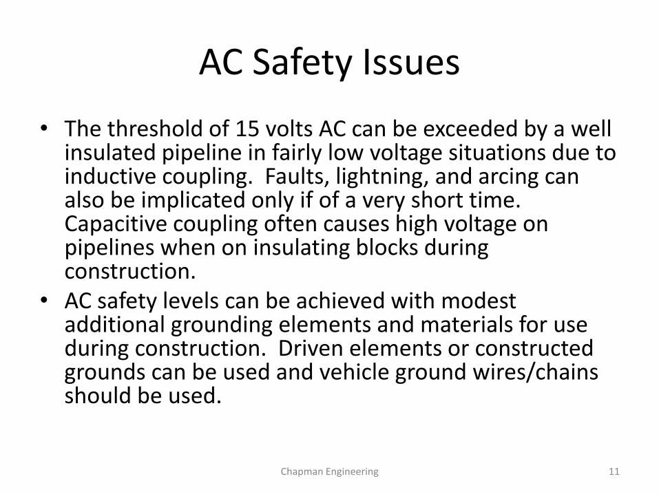
AC Safety Issues
• The threshold of 15 volts AC can be exceeded by a well insulated pipeline in fairly low voltage situations due to inductive coupling. Faults, lightning, and arcing can also be implicated only if of a very short time. Capacitive coupling often causes high voltage on pipelines when on insulating blocks during construction.
• AC safety levels can be achieved with modest additional grounding elements and materials for use during construction. Driven elements or constructed grounds can be used and vehicle ground wires/chains should be used.
Chapman Engineering 11
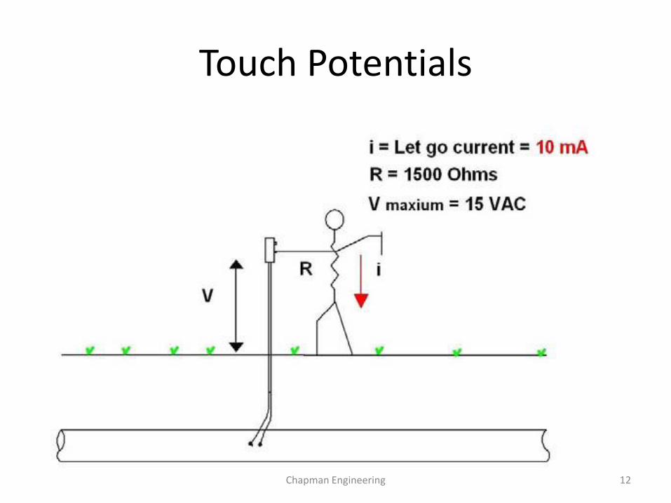
Touch Potentials
Chapman Engineering 12

Step Potentials
Chapman Engineering 13

Step Potential Mats
Chapman Engineering 14

Safety Hazard Voltages Very High
Chapman Engineering 15

Temporary Grounding/Construction
Chapman Engineering 16

How is AC Safety Mitigated?
• Locations of pipe to soil test leads, and any surface pipeline appurtenance can be measured to determine locations of possibly high enough voltage to require mitigation for safety. Accurate modeling will also disclose areas of expected safety issues.
• These locations can be mitigated with short runs of material that can permanently shunt the current to the power line ground system economically.
• Step potentials must be considered in these areas, and normally, step potential mats are indicated in all locations of surface pipe appurtenances such as block valves and risers to protect personnel
• All Test Lead contacts in high potential power line ROW parallel systems should be dead face front style to prevent contact with personnel. Covers are also indicated as further assurance of protection from public interaction in areas of high population densities.
Chapman Engineering 17

Other Safety Hazards
• Test leads directly to the pipeline can have dangerous AC Voltages, and should be of the “dead face front” style, so no electrical contact is possible to the person taking readings.
• Pipeline bonds also may have high AC Voltages in these areas and should also be constructed so no physical contact is made by the technician.
• Can you think of another significant possible shock hazard item in these areas?
Chapman Engineering 18
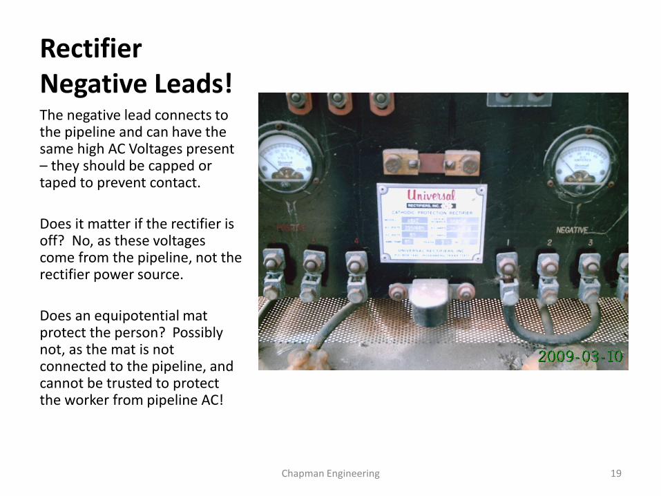
Rectifier Negative Leads!The negative lead connects to the pipeline and can have the same high AC Voltages present – they should be capped or taped to prevent contact.
Does it matter if the rectifier is off? No, as these voltages come from the pipeline, not the rectifier power source.
Does an equipotential mat protect the person? Possibly not, as the mat is not connected to the pipeline, and cannot be trusted to protect the worker from pipeline AC!
Chapman Engineering 19

Power Line Fault Example
Chapman Engineering 20

Substation Fault
Chapman Engineering 21

Lightning Damage - Arcing
Chapman Engineering 22

Faults
• Generally speaking faults are rare situations, but can have great effect on pipelines nearby, usually with implications of coating damage.
• Modeling calculations will evaluate the expected extent of fault currents near a pipeline and establish if the critical coating voltage may be exceeded.
• The electric power industry infrastructure is aging, however and may experience increasing fault situations across the country.
Chapman Engineering 23

AC Corrosion Characteristics
• AC corrosion is mainly due to inductive coupling which applies higher current values to a pipeline.
• Where the induced AC finds an opportunity to leave the pipeline, through an opening in the coating to the soil, low soil resistivity usually is needed to have significant AC corrosion.
• The main culprit is the AC Current Density.• The lower the soil resistivity and the smaller the
coating anomaly, the higher current density and the higher the probability of corrosion issues.
• Modeling looks at these iterations thousands of times along the pipeline segment for evaluation.
Chapman Engineering 24

What is Meant by AC Current Density?
• The current density level is important at the point of discharge from the pipeline into the soil.
• Reported data from field inspections have shown a range of AC current densities of 0 to 20A/m2 are not involved with AC corrosion. From 20A/m2 to 100A/m2 there may be an involvement, while levels over 100A/m2 are strongly indicated to have AC corrosion active.
Chapman Engineering 25

What affects the AC Current Density?
• High soil resistivities are an aide to protect the pipeline, by lowering the current density.
• Low soil resistivities enable higher current densities as the current flow away from the coating anomaly is enhanced.
• The size of the defect is critically important. Densities of current from a coating scrape of several inches in length will have lower current densities. While a small defect in the coating, such as made by a grain of sand in the coating will have much higher current densities as the current is being pushed from a much smaller cross sectional area.
Chapman Engineering 26

Further AC Current Density
• The availability of the current in the pipeline is also a major factor. If the pipeline is in a corridor with low AC current power lines, the critical current densities may be too low induced in the pipeline to be an issue, while large tower like lines with high voltages may indeed be involved with it. Each case is different, which points strongly to the need of field measurements and accurate modeling.
• Normally a length of pipe should be running parallel to an HVAC system to induce high current loads, but not always. In some crossings of shallow angles, these currents can still be achieved.
• There is an “end effect” situation as well, where current tries to preferentially leave the pipeline near the point of its deviations from being parallel.
Chapman Engineering 27

Bare Pipe or Coated - AC Implications
Chapman Engineering 28

How do we identify AC Corrosion?
• Field inspections of a suspected AC corrosion area should be exposed, but undisturbed prior to inspection. Cleaning or blasting them will erase critical clues to the cause of the corrosion.
• There are similarities between AC corrosion and MIC and may be misread by inspection, especially if the location has been cleaned.
• Both AC corrosion and MIC have a layered contour with each layer going deeper into the metal.
• Major differences may be that with MIC there likely is a smooth bottom to the pit, while with AC corrosion, the bottom may be somewhat level with small circular dimples scattered in the bottom.
• Measure the pH of liquid in the pit. A high pH is usually indicative of AC corrosion, while a low pH indicates possibly MIC is the corrosive agent.
• MIC can have some channel corrosion underneath the coating running away from the source of the corrosive acids produced along weak adhesion areas of the coating. Normally it is found that with AC corrosion, the corrosion is fairly locally confined and the coating may be disbonded only on the outer edges of the main pit.
Chapman Engineering 29
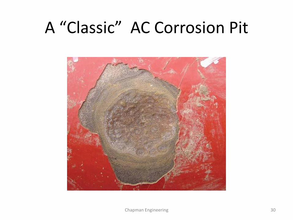
A “Classic” AC Corrosion Pit
Chapman Engineering 30

Point of AC Exit Example
Chapman Engineering 31

An Unusually Large AC Corrosion Anomaly
• Anomaly indications of CIS, DCVG, ACVG, and soil resistivity indicated the location as an excavation location.
• Upon excavation, a large anomalous ball of material was adhered to the pipe coating –much of the coating underneath was intact
Chapman Engineering 32

Upon Excavation
Chapman Engineering 33

Removed Corrosion Product Ball
Chapman Engineering 34

Area Under Corrosion Product
Chapman Engineering 35

Close Up of Corrosion Area
Chapman Engineering 36

Discussion
• The characteristic shapes of the AC corrosion are noted in the bottom of the pit.
• Layers of corrosion are evident in the pit outer walls, as well as indicated by rings in the corrosion product ball.
• Layers and rings of corrosion product are due to periods of higher current loads, and lower soil resistivity due to rains or soil moisture.
• The corrosion of .132” on a .403” wall indicates a corrosion loss of 32.8%. The time period is unknown.
Chapman Engineering 37

Look For the Characteristic Shapes/Orientations
Chapman Engineering 38

How do YOU Discover AC Corrosion?
• As PIM procedures mature, more emphasis on surveys will be required to detect AC issues especially in HCA’s.
• Reviewing AC readings on Test Leads, ECDA reports and as found by ILI pig runs with wall loss on the HVAC side - a big sign.
• Evaluate likelihood of AC corrosion by estimating current drain from 1cm^2 area, soil resistivity measured in field, and AC potential. Spreadsheet
• Request AC corrosion modeling (CDEGS-ROW, IRIS, others).
Chapman Engineering 39

What is needed for proper AC Mitigation Modeling?
Power Co. Data Needed
Proper AC mitigation modeling is based on information of the capabilities of the AC power system(s) and the orientation of the pipeline with the power lines, as well as the topography and other information.
Field survey work required is to determine separation distances, orientation angles and especially importantly, soil resistivity profiles.
Check with your AC Mitigation Modeling company for a document to be used for this data request.
Needed information:
Information can help reduce the overall cost of the grounding system. Accurate
information will reduce the number of overly conservative assumption that will have to
be made. Some information listed may not apply for this job.
Pipeline:
Plan & profile
Length of pipeline
What is at each end of the pipeline?
Does it connect to any other pipelines along the route?
Distance from electrical transmission and distribution lines that parallel the pipeline
What electrical lines cross the pipeline?
Location of above ground equipment such as valves or above ground piping
Buried depth of the pipe
Pipe diameter and wall thickness
Pipe coating and resistance value
Corrosion protection (CP) grounding system design
Grounding of pumping station
Any other grounding that connects to the pipeline
Transmission Lines that parallel the gas line
Plan & profile
Transmission structure drawings
Voltage of each circuit
Phase arrangement of each circuit
Maximum design current for each circuit
Fault current (magnitude and phase angle) at beginning and end of parallel to gas pipeline
for each circuit.
Number of shield wires and size of wire
Size and spacing of conductors.
Number conductors in bundle for each circuit
Grounding of structures (number and depth of ground rods)
Ground reading of structures
Pictures of structures
Aerial video of transmission line (geo referenced would be great)
Electric Generation site (when gas line connects to electric generation site)
Grounding system (switch yard and around generators).
Fault current (single phase fault) magnitude and phase angle
Current contribution from sources (step up transformers and from all lines)
Need structure information for all transmission lines that have shield wire that connects
to substation grid. Chapman Engineering 40

Field Tests to Enhance Modeling
Chapman Engineering 41

Construction, Pig Run, ECDA Insp.
Line 12" Diam 43.60 Miles
HCA 41.80 Miles
Confidence
Station Depth Length In. Dug ACVolts Comments Meas 090709 Ratio
465+53 21% 1.89
465+53 47% 3.25 2008 10.23 Installed 10 mag anodes and decoupler. 0.5VAC @0.5A 0.4468
674+91 19% 1.85
674+91 31% 1.28 2009 0.6129
675+01 10% 1.18
675+01 17% 1.00 2009 15.22 1.7000
2311+71 27% 1.30
2311+71 51% 0.88 2008 1.3 High concern area 1.8889
Scatter indicates good calibration ILI.
Wall thicknesses Loss Rate Per Year Depth Inches MPY Per
2001 2008 2009 Evaluating the wall loss rates 2008 2009 2008 MPY 2009 MPY VAC AC Volt
465+53 0.312 0.246 0.165 Loss rate 100% between 2008 and 2009 0.0094 0.0183 9.36 18.33 10.23 1.792
674+91 0.312 0.253 0.215 Loss rate 43% between 2008 and 2009 0.0085 0.0121 8.47 12.09
675+01 0.312 0.281 0.259 Loss rate 49% between 2008 and 2009 0.0045 0.0066 4.46 6.63 15.22 0.436
2311+71 0.312 0.228 0.153 Loss rate 65% between 2008 and 2009 0.0120 0.0199 12.03 19.89 1.3 15.300
AVG 8.58 14.24 8.92 5.84
Chapman Engineering 42

Calculate Amps/M^2
• Formula from 1995 NACE International paper
• Iac = (8* Vac)/(rho * pi *d)
• Iac is Current AC per m^2
• Vac is measured value
• Rho is soil resistivity in ohm meters
• D is diameter in meters (0.0113M)
Chapman Engineering 43

AC INTERFERENCE EQUATION:
I=8(VAC)/(ρ)(π)(d)
I = current density in A/m2
ρ = soil resistance in Ω-cm 350 Ω-cm
d = diameter of holiday in cm 1 CM
π = Pi 3.1415927
v = recorded AC voltage 2.5 VAC
Total: 182 A/m2
A penny has a diameter of 2.0 cmA nickel has a diameter of 2.2 cmA quarter has a diameter of 2.5 cm
Current Density
Chapman Engineering 44

AC INTERFERENCE EQUATION:
I=8(VAC)/(ρ)(π)(d)
I = current density in A/m2
ρ = soil resistance in Ω-cm 10000 Ω-cm
d = diameter of holiday in cm 1 CM
π = Pi 3.1415927
v = recorded AC voltage 30 VAC
Total: 76 A/m2
A penny has a diameter of 2.0 cmA nickel has a diameter of 2.2 cmA quarter has a diameter of 2.5 cm
AC Corrosion Theory - Current Density
Chapman Engineering 45

Spreadsheet for TL AC Surveys
Chapman Engineering 46
AC Corrosion Evaluation Spreadsheet
AC
Survey
Summar
y Mike Ames
Company [email protected]
Division Measured Results of
Area Field Meas Pipe Calculated Suggested
Line W/Half Cell Depth AC Mitigation
Note soil resistivity value at pipe depth. Enter VAC Resitivity Amps Comments
Location MP Description Type Date Technician AC P/S Ohm Cm M2 Ranges of Concern
Test Station #DIV/0! Results from 0 to 20 A/M2 no concern
Test Station #DIV/0! Results from 20 to 100 A/M2 corr0sion possible
Test Station #DIV/0! Results over 100 A/M2 corrosion probable
Test Station #DIV/0!
Test Station #DIV/0! Generally the higher the A/M2 over 100, the worse
Test Station #DIV/0! and higher the corrosion rate will be.
Test Station #DIV/0!
Test Station #DIV/0! Do not make changes in Yellow Column!
Test Station #DIV/0!
Test Station #DIV/0! Note: Safety hazard of shock if over 15 VAC !
Test Station #DIV/0!
Test Station #DIV/0!
Test Station #DIV/0!
Test Station #DIV/0!
Test Station #DIV/0!

T/L Annual Survey with AC PotentialsSurvey Summary
DCD >1 >4 >6 AC Density Suggested
Pipeline 12" Sta + VAC VAC VAC W/1cm Def Mitiga tion
>100 Likely For 2009 Deg
Location Date TechnicianAC P/S Comments
MS: 0+00 9/22/2009 JAMES EVANS0.394 25 .799 AC AMP ON BOND
MS: 35+38 9/22/2009 JAMES EVANS2.5 x 161
MS: 35+59 9/22/2009 JAMES EVANS2.5 x 161
MS: 35+60 9/22/2009 JAMES EVANS2.5 x 161
MS: 47+42 9/22/2009 JAMES EVANS1.394 x 90
MS: 78+57 9/22/2009 JAMES EVANS0.894 58
MS: 107+45 9/22/2009 JAMES EVANS1.76 x 113
MS: 176+21 9/22/2009 JAMES EVANS0.876 56
9/22/2009 JAMES EVANS0.906 58 NEW T/L
MS: 228+75 9/22/2009 JAMES EVANS0.888 57
MS: 263+64 9/22/2009 JAMES EVANS0.083 5 NEW T/L
MS: 311+56 9/22/2009 JAMES EVANS0.161 10
MS: 316+12 9/22/2009 JAMES EVANS0.77 50
MS: 364+50 9/22/2009 JAMES EVANS0.048 3
MS: 382+23 9/22/2009 JAMES EVANS0.088 6 NEW T/L
MS: 404+30 9/22/2009 JAMES EVANS0.171 11 NEW T/L
MS: 447+66 447+66 9/22/2009 JAMES EVANS8.561 x x x 551 Point Drains Could be horizontal - wide area
MS: 462+60 9/22/2009 JAMES EVANS4.91 x x 316 Mags at 0.17 ohms NEW T/L Loc of 10 Mag anodes - need drain here in near future.
MS: 491+74 491+74 9/22/2009 JAMES EVANS8.92 x x x 574 Point Drains if Possible Loc from 480+16 to 484+52
MS: 518+55 9/22/2009 JAMES EVANS1.234 x 79 NEW T/L
MS: 565+88 9/22/2009 JAMES EVANS0.988 64
MS: 583+27 9/22/2009 JAMES EVANS1.234 x 79 NEW T/L
MS: 617+34 9/22/2009 JAMES EVANS4.099 x x 264
MS: 665+67 668+67 9/22/2009 JAMES EVANS10.96 x x x 706 Horizontal Hor 1 NEW T/L Connect at MLV
MS: 668+67 9/22/2009 JAMES EVANS4.332 x x 279
MS: 774+65 9/22/2009 JAMES EVANS0.576 37
MS: 818+88 9/22/2009 JAMES EVANS0.79 51 NEW T/L
MS: 832+89 9/22/2009 JAMES EVANS1.389 x 89
MS: 876+45 9/22/2009 JAMES EVANS2.966 x 191 NEW T/L
MS: 910+21 9/22/2009 JAMES EVANS0.498 32 NEW T/L
MS: 913+78 9/22/2009 JAMES EVANS1.124 x 72
MS: 915+07 9/22/2009 JAMES EVANS0.269 17
MS: 929+70 9/22/2009 JAMES EVANS0.98 63 NEW T/L
MS: 959+26 9/22/2009 JAMES EVANS0.092 6 NEW T/L
MS: 971+12 9/22/2009 JAMES EVANS2.1 x 135
MS: 990+25 9/22/2009 JAMES EVANS2.5 x 161 NEW T/L
MS: 1012+23 9/22/2009 JAMES EVANS2.38 x 153
MS: 1050+10 9/22/2009 JAMES EVANS2.2 x 142 NEW T/L
MS: 1086+24 9/22/2009 JAMES EVANS1.207 x 78
MS: 1100+96 9/22/2009 JAMES EVANS1.604 x 103 NEW T/L
MS: 1133+37 9/22/2009 JAMES EVANS0.989 64
MS: 1181+58 9/22/2009 JAMES EVANS0.544 35
MS: 1231+80 9/22/2009 JAMES EVANS2.64 x 170
MS: 1254+48 9/22/2009 JAMES EVANS3.72 x 240
MS: 1270+87 9/22/2009 JAMES EVANS4.29 x x 276
MS: 1276+64 1276+64 9/22/2009 JAMES EVANS5.52 x x x 355 Horizontal Hor 2 Open area, no surface pipe
MS: 1288+47 9/22/2009 JAMES EVANS2.168 x 140 NEW T/L
MS: 1304+25 9/22/2009 JAMES EVANS4.26 x x 274
MS: 1315+41 9/22/2009 JAMES EVANS4.26 x x 274
MS: 1326+00 9/22/2009 JAMES EVANS4.35 x x 280
MS: 1360+90 9/22/2009 JAMES EVANS3.294 x 212
MS: 1388+80 9/22/2009 JAMES EVANS1.446 x 93
MS: 1395+30 9/22/2009 JAMES EVANS1.688 x 109
MS: 1415+65 9/22/2009 JAMES EVANS1.184 x 76
MS: 1447+89 9/22/2009 JAMES EVANS1.542 x 99
MS: 1447+90 9/22/2009 JAMES EVANS1.542 x 99
MS: 1451+47 9/22/2009 JAMES EVANS1.565 x 101 NEW T/L
MS: 1459+65 9/22/2009 JAMES EVANS1.408 x 91
MS: 1466+85 9/22/2009 JAMES EVANS1.221 x 79
MS: 1484+20 9/22/2009 JAMES EVANS0.439 28
MS: 1499+49 9/22/2009 JAMES EVANS0.445 29
MS: 1523+41 9/22/2009 JAMES EVANS1.007 x 65
VAC>1 39
7 VAC>4 11
Chapman Engineering 47

Graph AC Potentials
0.000
2.000
4.000
6.000
8.000
10.000
12.000
1 3 5 7 9 11 13 15 17 19 21 23 25 27 29 31 33 35 37 39 41 43 45 47 49 51 53 55 57 59 61
AC Volts - 1.8 VAC Critical This Case
AC…
Chapman Engineering 48

Graph AC Current Density
0
100
200
300
400
500
600
700
800
1 3 5 7 9 11 13 15 17 19 21 23 25 27 29 31 33 35 37 39 41 43 45 47 49 51 53 55 57 59 61
AC AmpsM^2
AC AmpsM^2
Chapman Engineering 49

Cell Phone/Camera Apps - Geocam
Chapman Engineering 50

Cell Phone Apps - EMF
Gauss Meter Ultimate EMF Detector
Chapman Engineering 51

App - Lightning
• Can be used to determine if lightning is approaching or leaving your area.
• Some use for company stop work limitation.
• Bottom line, be safe!
• Essentially times sound from any event to you.
Chapman Engineering 52

LEF/EMF TESTING
NACE course manual CP level 2 [1] refers to the longitudinal electrical field (LEF)
measurement with horizontal wire, called LEF-probe as a common practice to obtain an impression on the current power line load during site visit.
This wire is well-insulated, grounded at both ends and shall be placed on the ground parallel to the powerline.
The AC voltage induced in the wire is measured with an accurate high-impedance voltmeter. The measured voltage divided by the wire length, is approximately equal to the magnitude of the LEF.
Chapman Engineering 53
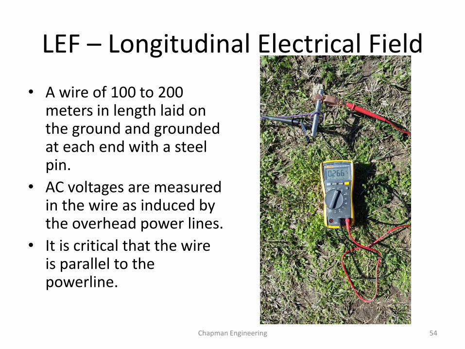
LEF – Longitudinal Electrical Field
• A wire of 100 to 200 meters in length laid on the ground and grounded at each end with a steel pin.
• AC voltages are measured in the wire as induced by the overhead power lines.
• It is critical that the wire is parallel to the powerline.
Chapman Engineering 54

EMF – Electromagnetic Field
Chapman Engineering 55

Using EMF to locate LEF Tests

Spreadsheet for LEF/EMF/Soil Resistivity
Chapman Engineering 57
LEF Cable: 465 feet #12 dual coated stranded Time: 12:30p Company:
Steel tent Stakes at each end. Date: 1/8/2019 Pipeline:
LEF ACV Proposal:
From: 0.345 From:
to: To:
From: 0.601 FT: Ohms Multiplier
To: 2.5 10.7 1
Note pipe PI's here in the middle of the run at 28.58266430, -99.20746389 5 6.6 1
Gauss From Trifield Meter 7.5 5 1
Reading 10 4 1
8.1 15 3.2 1
9.94 20 2.5 1
12.31 10 ohm 10 1
16.22
20.3
24.07
27.38
27.38
27.96 Under power line, note power line is vertical 3 cables.
25.56
20.05
15.84 tree line
Site 1
GPS
28.5821140, -99.20773487
28.58295688, -99.20806933
28.58209467, -99.20767229
GPS
Soil Resistivity
28.58208032, -99.20765466
28.58212463, -99.20746555
28.58256949, -99.20755520
28.58299046, -99.20803449
Over Pipe
Test station reads -1.333 dcv and 5.998 vac.
At 28.5821140, -99.20773487
28.58247214, -99.20730000
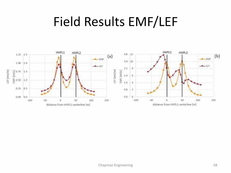
Field Results EMF/LEF
Chapman Engineering 58

Field Test EMF Trifield On Ground
Chapman Engineering 59

Modeling vs Field Tests
Chapman Engineering 60

AC Defects Found by Field Tests and ILI
Chapman Engineering 61

Quote from Paper CP11 - Corcon
Chapman Engineering 62
A sensitivity study demonstrates however that the LEF measurement as discussed in NACE interference course should be taken with caution. Interpretation of the LEF reading is difficult in the case of power lines with horizontally aligned circuits. LEF is more prone to errors related to misalignment of the probe with respect to the power line.
Therefore EMF measurements are preferred because they provide unambiguous information on the power line load characteristic and interference.
The use of LEF and EMF was demonstrated in real-world examples. The measurement values have been used to calibrate the power line characteristics in the computational model. As such realistic pipeline interference levels are simulated resulting in a more precise and cost-effective mitigation design.

AC Corrosion - Summary• Induced AC voltage may be a cause of corrosion at coating defects
where AC current escapes the pipe wall into the soil.
• Small rather than large coating defects are susceptible to AC corrosion effects.
• The surface area of the pipe at a coating holiday is important since the corrosion rate increases with increasing current density.
• Large holidays would have a lower current density than small holidays if both were exposed to the same soil conditions.
• Modeling can be enhanced and perhaps replace missing data by field testing with EMF and LEF techniques.
Chapman Engineering 63

Questions or Comments
For technical support – Free survey software:
Mike Ames - “[email protected]”
Chapman Engineering
Houston, TX
713 598 7042 cell, 800-375-7747 office
www.chapman.engineering
Chapman Engineering 64

Mitigation Systems
Chapman Engineering 65

How are AC Corrosion Issues Mitigated?
• A cookie cutter approach may be used, but cannot be assured of success as there may be areas that have not been modeled and found that can have significant issues of AC corrosion that may not be covered by short isolated segments of parallel or deep well drains.
• Areas for spot installations or longer runs of material may be disclosed by a good interpretation of the topography, and looking for areas of divergence and convergence between the pipeline and the power lines involved.
• Areas of known high current density may be generally indicated at major divergence points, and near power line substations, but many others may be on the line, and not discovered without field surveys and appropriate modeling of the systems. It is strongly suggested any line with discovered AC corrosion wall losses should be modeled and an appropriate complete system installation designed and proposed for consideration.
Chapman Engineering 66
What Modeling Does - Summary
• Establishes AC voltage touch and step levels• Establishes concerns and locations of possible
coating damage from fault currents• Establishes the location and resistance values
required for dissipating induced AC from the pipeline segment.
• Projects future changes of growth of HVAC system and new mitigation needs.
• It efficiently establishes the mitigation needs of the given pipeline segment, saving costs.
Chapman Engineering 67

Are Simple Fixes Enough?
Chapman Engineering 68

AC Mitigation – Modeling Defines What is Required and Where
• Mitigation wire provides a benefit in the mitigation of AC corrosion. For a coating holiday located in the vicinity of the mitigation wire, the effective resistance of the holiday is increased due to the mutual resistance between the holiday and the mitigation wire, thereby reducing the AC current density at the holiday.
Chapman Engineering 69

Typical Solid Media AC Mitigation – Single Linear
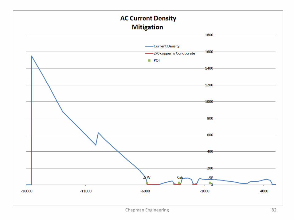
To the side of the pipe nearest the power line, a long trench is made for the installation of mitigation media. In this case a bare copper wire is used with a layer of conductive concrete.
The conductive concrete lowers the resistance of the system, protects the copper wire from corrosion, and lowers the impedance value of the wire to allow faster dissipation of fault currents.
Zinc wire or ribbon can also be used, but should have a surrounding prepared backfill .
Modeling will determine the length, location, wire size, and placement of these systems.
Chapman Engineering 70

Types of AC Mitigation for Corrosion Control
• Linear grounding systems – allow the dissipation of AC current through the soil back to the power line grounding.– Various materials are used including zinc, copper, and
steel
• Point Drain grounding – these systems are similar to deep wells in that they use vertical elements into the soil to achieve low resistance grounding to carry localized area AC currents back to the power line system.– Normally for low angle crossings or deviation points
Chapman Engineering 71

Grounding Materials Used
• Zinc Ribbon or Wire• Zinc over steel wire• Copper Wire• Combination Steel over
Copper Wire• Steel Wire
• Common Backfills– Native Soil– Bentonite– Conductive Concretes
Chapman Engineering 72

Field Installations of Linear AC Drains
Chapman Engineering 73

Results Copper/Conductive Concrete
0.000
1.000
2.000
3.000
4.000
5.000
6.000
1
12
23
34
45
56
67
78
89
10
0
11
1
12
2
13
3
14
4
15
5
16
6
17
7
18
8
19
9
21
0
22
1
23
2
24
3
25
4
26
5
27
6
28
7
29
8
30
9
32
0
33
1
34
2
35
3
36
4
37
5
38
6
39
7
40
8
41
9
43
0
Series1
Chapman Engineering 74

Point Drains
Chapman Engineering 75

AC Interaction on Municipal Lines
• A common misconception is that there is no need for AC Mitigation on city mains or small intrastate pipeline systems.
• AC can be induced to high levels on these lines even from low municipal AC systems.
• Key locations may be– New well coated lines parallel to AC systems
– Passing by an HVAC Substation
– Buried AC Systems crossing at shallow angles and little separation from the pipeline
Chapman Engineering 76

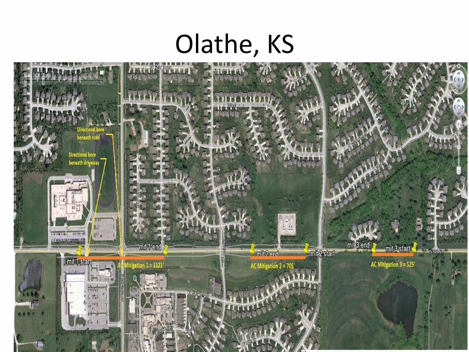
Point Drains in Kansas
• The location was near a power sub station
• The company had installed zinc ribbon and bare copper wire tests and tested copper wire with a conductive concrete backfill
• Prior to installation of the point drains, an AC Current Density monitor coupon was installed
Chapman Engineering 77
Model Results
• The models presented are to show the unmitigated Voltage and Current ranges in their current status and in their post mitigated status.
• These models were produced using the available information from the facility owner, the power line company, and field inspections of the areas concerned.
Chapman Engineering 78
Olathe, KS
Chapman Engineering 79

Chapman Engineering 80

Chapman Engineering 81
Chapman Engineering 82

Our New Reality ROW
Chapman Engineering 83

Would your AC Mitigation System Survive?
Chapman Engineering 84