academic hand book 2017-2018 ii b. tech eee i ...vallurupalli nageswara rao vignana jyothi institute...
TRANSCRIPT
VALLURUPALLI NAGESWARA RAO VIGNANA JYOTHI INSTITUTE OF ENGINEERING & TECHNOLOGY
AN AUTONOMOUS INSTITUTE
(Approved by AICTE - New Delhi, Govt. of A.P.)
Accredited by NBA and NAAC with ‘A’ Grade
Vignana Jyothi Nagar, Bachupally, Nizampet (S.O.), Hyderabad-500 090. A.P., India.
ACADEMIC HAND BOOK
2017-2018
II– B. TECH EEE
I SEMESTER

VNR VIGNANA JYOTHI INSTITUTE OF ENGINEERING AND TECHNOLOGY
AN AUTONOMOUS INSTITUTE
VISION
A Deemed University of Academic Excellence, for National and International Students
Meeting global Standards with social commitment and Democratic Values
MISSION
To produce global citizens with knowledge and commitment to strive to enhance quality of
life through meeting technological, educational, managerial and social challenges
QUALITY POLICY
• Impart up to date knowledge in the students chosen fields to make them quality Engineers
• Make the students experience the applications on quality equipment and tools.
• Provide quality environment and services to all stock holders.
• Provide Systems, resources and opportunities for continuous improvement.
• Maintain global standards in education, training, and services


VNR VIGNANA JYOTHI INSTITUTE OF ENGINEERING AND TECHNOLOGY
BACHUPALLY, NIZAMPET (S.O), HYDERABAD – 500090
LESSON PLAN: 2017-18
II B. Tech : I Sem : EEE L T/P/D C
3 0 3
Course Name: Network Analysis Course Code: 5EE02
Names of the Faculty Member: G.C.Prabhakar & Dr. J.Srinivasa Rao
Number of working days: 93-(mid 5)-(holidays10)=78
Number of Hours/week: 5
Total number of periods planned: 78
1. PREREQUISITES
Circuit Theory (5EE01), Ordinary Differential Equations and Laplace Transforms (
2. COURSE OBJECTIVES
The student should be able
• To understand Three phase circuits. • To analysis transients in Electrical systems. • To evaluate Network parameters of given
Electrical network and design of filters. • To apply Fourier analysis to Electrical systems
3. COURSE OUTCOMES (COs)
Upon completion of this course the student is able to
1. Describe The importance of three phase circuit for balanced and unbalanced conditions
2. Analyze the transient behavior of electrical networks in time domain and frequency domain.
3. Illustrate the concept of complex frequency, transform impedance, significance of poles and zeros of a given transfer
function and network synthesis.
4. Describe the properties of Fourier transforms and their applications to Electrical Systems.

4. MAPPING OF COs WITH POs
Course
Outcomes
(COs)
Program Outcomes (POs)
A b c d e f g h i J k l
CO 1 3 2 2 2 2 3
CO 2 3 2 1 2 1 2 2
CO 3 2 2 1 1 2 2 2 2 1 2 3
CO 4
3: High correlation, 2: Moderate correlation and 1: Low Correlation
5. LEARNING RESOURCES
(i) TEXT BOOKS
1. Engineering circuit analysis by William Hayt and Jack E. Kemmerly, Mc Graw Hill Company, 6th edition.
2. Network Analysis by A. Sudhakar, Shyammohan Palli, Mc Graw Hill Company
3. Fundementals of electric circuits by Charles k Alexander, Mathew N O Sadiku, Tata Mc Graw Hill Company, 3rd Edition
4. Network Analysis by M. E Van valkenburg, PHI.
5.Circuit Theory by A. Chakrabarti, Dhanipat Rai and Co., 6th edition.
6. Electric circuit analysis by C. L. Wadhwa, New Age international.
7. Basic circuit analysis by D. R, Cunningham and J. A Stuller, Jaico Publications.
8. Electrical Circuit theory by K. Rajeswaran, Pearson Education 2004.
9. Network Theory and Filter Design by Vasudev K. Aatre, Eastern Wiley Publishers, 1993.
10. Electric Circuits by Mahmood Nahvi, Joseph A edmister, Schaum's Outline,Fifth Edition.

11. Electric circuit analysis by B. Subrahmanyam, I. K international.
(a) Open Learning Resources for self learning
L1. http://nptel.ac.in/courses
L2. https://ocw.mit.edu
L3. https://www.coursera.org
(iii) JOURNALS
J1. IEEE Journal on circuits.
6. DELIVERY METHODOLOGIES
DM1: Chalk and Talk DM5: Open The Box
DM2: Learning by doing DM6: Case Study (Work on real data)
DM3: Collaborative Learning (Think Pair Share, POGIL, etc.) DM7: Group Project
DM4: Demonstration (Physical / Laboratory / Audio Visuals)
7. PROPOSED FIELD VISITS/ GUEST LECTURE BY INDUSTRY EXPERT
8. ASSESSMENT

AM1: Semester End Examination . AM2: Mid Term Examination
AM3: Home Assignments
AM6: Quizzes
AM7: Course Projects**
9. WEIGHTAGES FOR PROPOSED ASSESSMENT METHODOLOGIES
R15
S. No. Assessment Methodology Weightages in marks for the
courses with Course project
Weightages in marks for
the courses without
Course project
1. Home Assignments (AM3) 3%
10
5% 10
2. Quizzes (AM6) 3% 5%
3. Course project (AM7) 4% -
4. Mid Term Examination (AM2) 30 30
5. Semester End Examination (AM1) 60 60
(i) HOME ASSIGNMENTS
On the beginning day of each unit, home assignment sheet is given to the students and the solution sheet for the same is expected
after two days of the completion of unit.
(ii) QUIZZES
Two quizzes are conducted in the course duration. One is scheduled on 31/08/2017 and the second one is scheduled on 01/11/2017.
(iii) COURSE PROJECTS
One course project is assigned to each project batch of size three in the beginning of the course and assessed at the end of the
course. One midterm evaluation is carried out to monitor the progress of the project and the team coherence.
i). Design of relay driver circuit driven by pulsed voltage source
ii).Design of power factor correction equipment
iii).Design of portable hazard blinker
iv).Design of inductor based solar energy storage system
v).Design of a electronic call bell vi) Measurement of power delivered by a three phase heater installed in a hot water.
10. SIMULATION SOFTWARES
1. PSpice
2. MATLAB
11. DETAILED COURSE DELIVERY PLAN
UNIT –I
THREE PHASE CIRCUITS: Three phase circuits: Phase sequence – Star and Delta connection – Relation between line and phase
voltages and currents in balanced systems – Analysis of balanced and Unbalanced 3 phase circuits – Measurement of Active and
Reactive Power- Different methods-Problems
LEARNING OUTCOMES
After completion of this unit the student will be able to
1. Distinguish between the single phase, two phase and three phase system
2. Formulate the relation between line and phase quantities of a star and delta systems
3. Convert star network to delta network vice versa.

4. Measure reactive and active power in 3-phase system by different methods
TEACHING PLAN
S.
No. Contents of syllabus to be taught
No. of
Lecture
Periods
Lecture
Dates
Proposed Delivery
Methodologies
Learning Resources /
References
(Text Books /
Journals /
Publications/ Open
Learning Resources)
Course
Outcomes
43. Introduction of three phase circuits 1 3-7-17
DM1. Chalk and Talk (along
with PPT)
DM4. Demonstration of
one example.
L.1.
T.1& T.2
CO1
44. Phase sequence 1 4-7-17
DM1. Chalk and Talk
DM4. Detailed analysis with
the help of simulation
model
T.1 & T.5
CO1
45. Star and Delta connection 1 5-7-17
DM1. Chalk and Talk
DM4. Detailed analysis with
the help of simulation
model
T.1 & T.5
CO1

46.
Relation between line and phase
voltages and currents in balanced
systems
1 6-7-17
DM1. Chalk and Talk
DM4. Detailed analysis with
the help of simulation
model
T.1, T.5 & L4
CO1
47.
Relation between line and phase
voltages and currents in balanced
systems
1 8-7-17 DM1. Chalk and Talk. T.1& T.5
CO1
48. Analysis of balanced and Unbalanced 3
phase circuits 1 12-7-17
DM1. Chalk and Talk
DM4. Detailed analysis with
the help of simulation
model
T.1 & T.5
CO1
49. Analysis of balanced and Unbalanced 3
phase circuits 1 13-7-17
DM1. Chalk and Talk
DM4. Detailed analysis with
the help of simulation
model
T.1 & T.5
CO1
50. Problems 1 15-7-17
DM1. Chalk and Talk
DM4. Detailed analysis with
the help of simulation
model
T.1& T.5
CO1

51. Problems 1 16-7-17 DM1. Chalk and Talk T.1, T.2 & T.5
CO1
52. Problems 1 17-7-17
DM1. Chalk and Talk
DM4. Detailed analysis with
the help of simulation
model
T.1, T.5
CO1
53. Measurement of Active and Reactive
Power 1 19-7-17
Tutorial
DM1. Chalk and Talk T.1, T.2 & T.5
CO1
54. Measurement of Active and Reactive
Power 1 20-7-17
DM1. Chalk and Talk
DM4. Detailed analysis with
the help of simulation
model
T.1 & T.5
CO1
55. Problems 1 21-7-17
DM1. Chalk and Talk
DM4. Detailed analysis with
the help of simulation
model
T.1 & T.5
CO1
56. Problems 1 22-7-17
Tutorial
DM3: Collaborative
Learning -Think Pair Share
T.1, T.2 & T.5
CO1

57. Problems 1 24-7-17
DM1. Chalk and Talk
DM4. Detailed analysis with
the help of simulation
model
T.1, T.5 & L4
CO1
58. Problems 1 25-7-17
DM1. Chalk and Talk
DM4. Detailed analysis with
the help of simulation
model
T.1, T.2 & T.5
CO1
59. Problems 1 26-7-17
Tutorial
DM3: Collaborative
Learning -Think Pair Share
T.1, T.2 & T.5
CO1
60. Problems 1 29-7-17 DM1.Power point
presentation. All Unit-II publications.
CO1
TUTORIAL QUESTIONS
In the network shown in fig below switch is closed at t=0. Determine ,di
idt
.

HOME ASSIGNMENT-II
Issue date: 22/07/2017 Submission date: 28/08/2017
1.Determine the currents in unbalanced star connected load supplied from symmetrical 3-pahse, 400V system. The
branch impedance of the loads are 010 30AZ = Ω, 010 45BZ = Ω , 010 60CZ = Ω .The phase sequence is A-B-C.
CO2
UNIT- II
TRANSIENT ANALYSIS: Transient response of R-L, R-C, R-L-C circuits (Series and parallel combinations) for D.C. and
sinusoidal excitations – Initial conditions - Solution using differential equation approach and Laplace transforms. Response of R-
L, R-C, R-L-C circuits for step, ramp, pulse and impulse excitation using Laplace Transform Methods.
LEARNING OUTCOMES
After completion of this unit the student will be able to
5. Analyse the operation of single phase fully controlled converter with R, RL and RLE load.
TEACHING PLAN
S.
No. Contents of syllabus to be taught
No. of
Lecture
Periods
Lecture
Dates
Proposed Delivery
Methodologies
Learning Resources /
References
(Text Books /
Journals /
Publications/ Open
Learning Resources)
Course
Outcomes
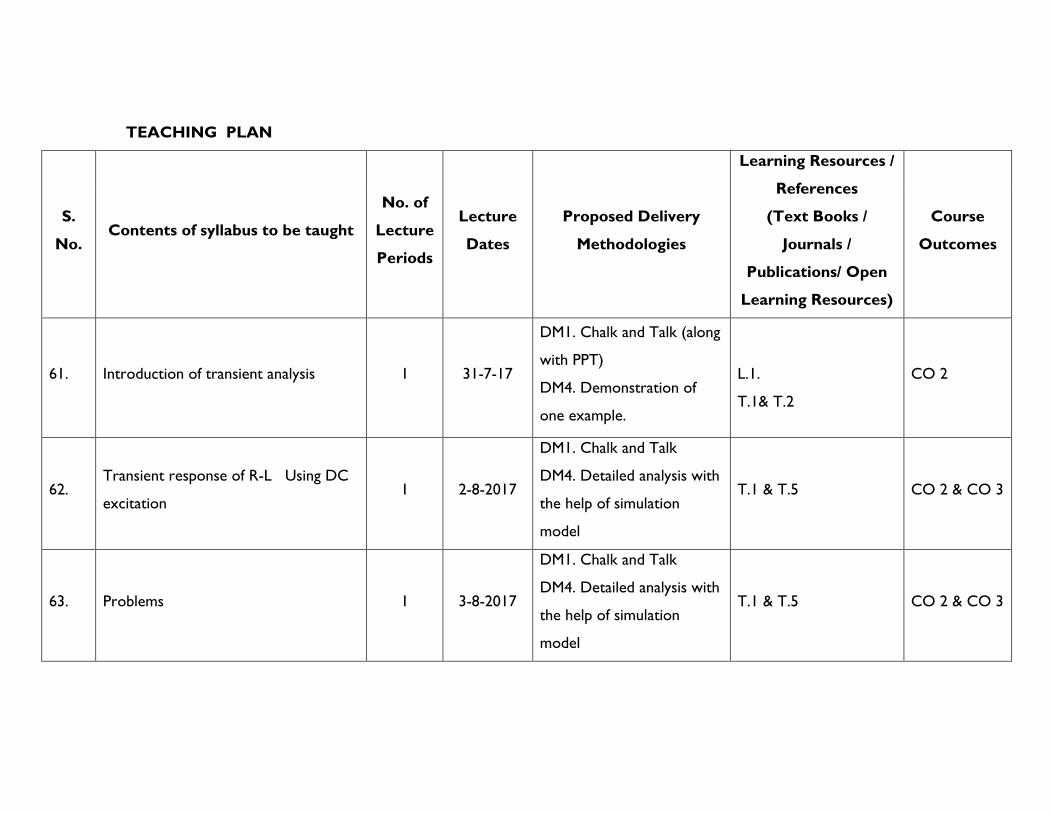
61. Introduction of transient analysis 1 31-7-17
DM1. Chalk and Talk (along
with PPT)
DM4. Demonstration of
one example.
L.1.
T.1& T.2
CO 2
62. Transient response of R-L Using DC
excitation 1 2-8-2017
DM1. Chalk and Talk
DM4. Detailed analysis with
the help of simulation
model
T.1 & T.5 CO 2 & CO 3
63. Problems 1 3-8-2017
DM1. Chalk and Talk
DM4. Detailed analysis with
the help of simulation
model
T.1 & T.5 CO 2 & CO 3

64. Transient response of R-C Using DC
excitation, 1 4-8-2017
DM1. Chalk and Talk
DM4. Detailed analysis with
the help of simulation
model
T.1, T.5 & L4 CO 2 & CO 3
65. Transient response of R-L-C Using DC
excitation 1 8-8-2017 DM1. Chalk and Talk. T.1& T.5 CO 2 & CO 3
66. Transient response of R-L Using AC
excitation 1 9-8-2017
DM1. Chalk and Talk
DM4. Detailed analysis with
the help of simulation
model
T.1 & T.5 CO 2 & CO 3
67. Transient response of R-C Using AC
excitation 1 10-8-2017
DM1. Chalk and Talk
DM4. Detailed analysis with
the help of simulation
model
T.1 & T.5 CO 2 & CO 3
68. Transient response of R-L-C Using AC
excitation 1 12-8-2017
DM1. Chalk and Talk
DM4. Detailed analysis with
the help of simulation
model
T.1& T.5 CO 2 & CO 3

69. Initial conditions 1 12-8-2017 DM1. Chalk and Talk T.1, T.2 & T.5 CO 2 & CO 3
70. Solution using differential equation
approach and Laplace transforms 1 13-8-2017
DM1. Chalk and Talk
DM4. Detailed analysis with
the help of simulation
model
T.1, T.5 CO 2 & CO 3
71. Response of R-L, R-C circuits for step,
ramp, pulse and impulse excitation 1 14-8-2017
Tutorial
DM1. Chalk and Talk T.1, T.2 & T.5 CO 2 & CO 3
72. Response of R-L-C circuits for step,
ramp, pulse and impulse excitation 1 15-8-2017
DM1. Chalk and Talk
DM4. Detailed analysis with
the help of simulation
model
T.1 & T.5 CO 2 & CO 3
73. Laplace Transform Methods 1 17-8-2017
DM1. Chalk and Talk
DM4. Detailed analysis with
the help of simulation
model
T.1 & T.5 CO 2 & CO 3
74. Problems 1 19-8-2017 Tutorial
DM3: Collaborative T.1, T.2 & T.5 CO 2 & CO 3

Learning -Think Pair Share
75. Problems 1 22-8-2017
DM1. Chalk and Talk
DM4. Detailed analysis with
the help of simulation
model
T.1, T.5 & L4 CO 2 & CO 3
76. Problems 1 23-8-2017
DM1. Chalk and Talk
DM4. Detailed analysis with
the help of simulation
model
T.1, T.2 & T.5 CO 2 & CO 3
77. Problems 1 24-8-2017
Tutorial
DM3: Collaborative
Learning -Think Pair Share
T.1, T.2 & T.5 CO 2 & CO 3
78. Problems 1 26-8-2017 DM1.Power point
presentation. All Unit-II publications. CO 2 & CO 3
TUTORIAL QUESTIONS
Write the properties of the Driving Point function of RC Networks. HOME ASSIGNMENT-II
Issue date: 22/07/2017 Submission date: 28/08/2017
Find the current ( )i t for the series RC network if R=1Ω, 1
2C F=

UNIT- III
NETWORK FUNCTIONS & SYNTESIS: The Complex Frequency- concept -Physical interpretation - Transform Impedance and
Transform Circuits, Series and parallel Combination of Elements, Terminal Pairs or Ports, Network Functions for One-port and
Two-port, Poles and Zeros of Network Functions,
62
Significance of poles and Zeros, Properties of Driving Point Functions, Properties of Transfer functions, Necessary Conditions
for Transfer Functions, Time Domain Response from Pole Zero Plot.Synthesis of one port LC, RL and RC networks – Foster
and Cauer methods.
LEARNING OUTCOMES
After completion of this unit the student will be able to
6. Analyse the operation of single phase fully controlled converter with R, RL and RLE load.
TEACHING PLAN
S.
No. Contents of syllabus to be taught
No. of
Lecture
Periods
Lecture
Dates
Proposed Delivery
Methodologies
Learning Resources /
References
(Text Books /
Journals /
Publications/ Open
Learning Resources)
Course
Outcomes
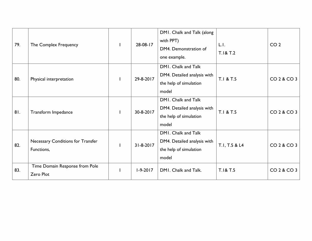
79. The Complex Frequency 1 28-08-17
DM1. Chalk and Talk (along
with PPT)
DM4. Demonstration of
one example.
L.1.
T.1& T.2
CO 2
80. Physical interpretation 1 29-8-2017
DM1. Chalk and Talk
DM4. Detailed analysis with
the help of simulation
model
T.1 & T.5 CO 2 & CO 3
81. Transform Impedance 1 30-8-2017
DM1. Chalk and Talk
DM4. Detailed analysis with
the help of simulation
model
T.1 & T.5 CO 2 & CO 3
82. Necessary Conditions for Transfer
Functions, 1 31-8-2017
DM1. Chalk and Talk
DM4. Detailed analysis with
the help of simulation
model
T.1, T.5 & L4 CO 2 & CO 3
83. Time Domain Response from Pole
Zero Plot 1 1-9-2017 DM1. Chalk and Talk. T.1& T.5 CO 2 & CO 3

84. Time Domain Response from Pole
Zero Plot 1 1-9-2017
DM1. Chalk and Talk
DM4. Detailed analysis with
the help of simulation
model
T.1 & T.5 CO 2 & CO 3
85. Synthesis of one port LC Networks 1 2-9-2017
DM1. Chalk and Talk
DM4. Detailed analysis with
the help of simulation
model
T.1 & T.5 CO 2 & CO 3
86. Synthesis of one port RC networks 1 3-9-2017
DM1. Chalk and Talk
DM4. Detailed analysis with
the help of simulation
model
T.1& T.5 CO 2 & CO 3
87. Synthesis of one port R L networks 1 4-9-2017 DM1. Chalk and Talk T.1, T.2 & T.5 CO 2 & CO 3
88. Foster and Cauer methods.
1 5-9-2017
DM1. Chalk and Talk
DM4. Detailed analysis with
the help of simulation
model
T.1, T.5 CO 2 & CO 3

89. Foster and Cauer methods.
1 6-9-2017
Tutorial
DM1. Chalk and Talk T.1, T.2 & T.5 CO 2 & CO 3
90. Foster and Cauer methods.
1 7-9-2017
DM1. Chalk and Talk
DM4. Detailed analysis with
the help of simulation
model
T.1 & T.5 CO 2 & CO 3
91. Problems 1 8-9-2017
DM1. Chalk and Talk
DM4. Detailed analysis with
the help of simulation
model
T.1 & T.5 CO 2 & CO 3
92. Problems 1 12-9-2017
Tutorial
DM3: Collaborative
Learning -Think Pair Share
T.1, T.2 & T.5 CO 2 & CO 3
93. Problems 1 14-9-2017
DM1. Chalk and Talk
DM4. Detailed analysis with
the help of simulation
model
T.1, T.5 & L4 CO 2 & CO 3
94. Problems 1 16-9-2017
DM1. Chalk and Talk
DM4. Detailed analysis with
the help of simulation
model
T.1, T.2 & T.5 CO 2 & CO 3
95. Problems 1 17-9-2017
Tutorial
DM3: Collaborative
Learning -Think Pair Share
T.1, T.2 & T.5 CO 2 & CO 3
96. Problems 1 18-9-2017 DM1.Power point
presentation. All Unit-II publications. CO 2 & CO 3
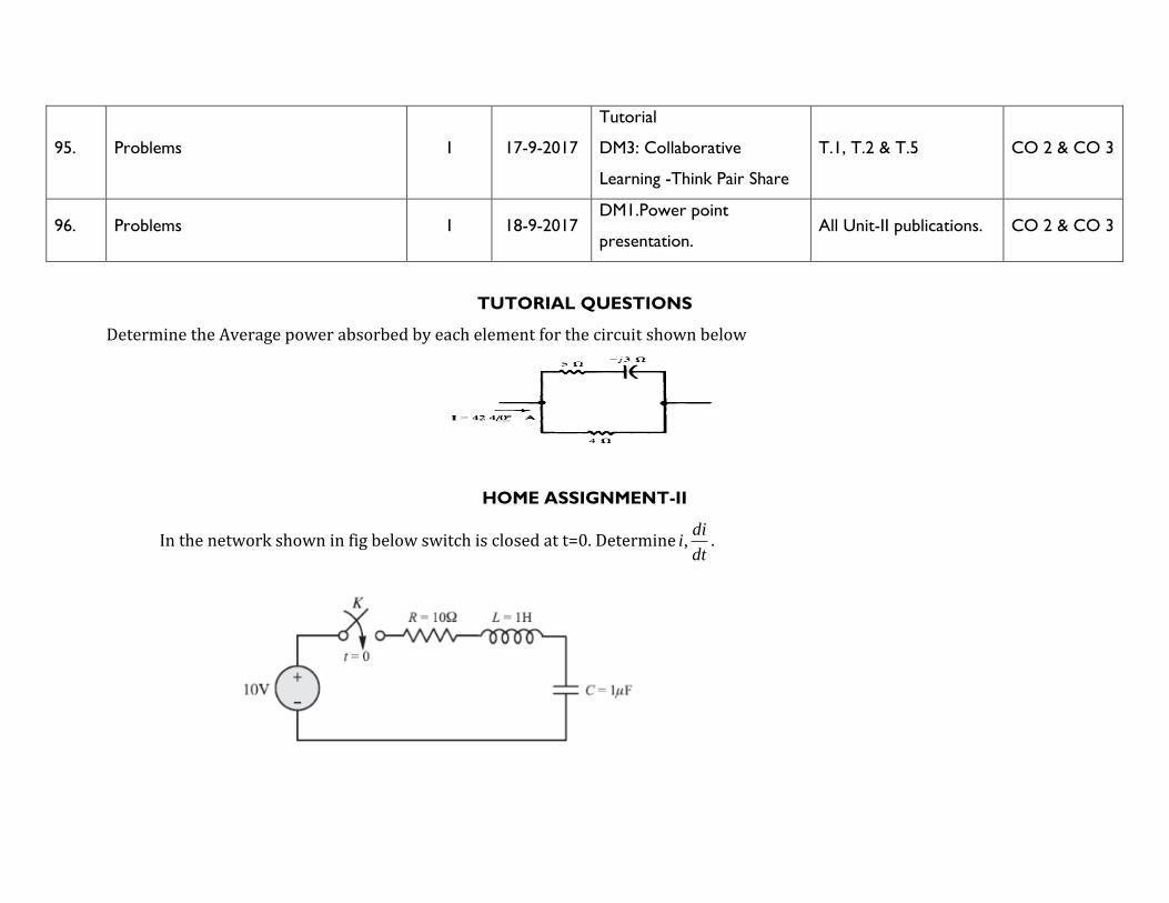
TUTORIAL QUESTIONS
Determine the Average power absorbed by each element for the circuit shown below
HOME ASSIGNMENT-II
In the network shown in fig below switch is closed at t=0. Determine ,di
idt
.

UNIT- IV
NETWORK PARAMETERS & FILTERS: Impedance parameters, Admittance parameters, Hybrid parameters, Transmission
(ABCD) parameters, conversion of Parameters from one form to other, Conditions for Reciprocity and Symmetry,
Interconnection of Two Port networks in Series, Parallel and Cascaded configurations, Image Parameters, Illustrative problems.
Classification of filters – Low pass, High pass, Band pass and Band Elimination, Constant-k and M-derived filters-Low pass and
High pass Filters (qualitative and quantitative treatment) and Band pass and Band elimination filters (quantitative treatment only),
Illustrative problems.
LEARNING OUTCOMES
After completion of this unit the student will be able to
1. Identify the symmetrical and reciprocal network based upon the conditions for all types of parameters
2. Analyze the process of conversion of Parameters from one form to other
3. Know the importance and applicability of image parameters
4. Design the different types of filters
TEACHING PLAN
S. No. Contents of syllabus to be taught
No. of
Lecture
Periods
Lecture
Dates
Proposed Delivery
Methodologies
Learning Resources /
References
(Text Books /
Journals /
Publications/ Open
Course
Outcomes

Learning Resources)
55
Impedance parameters, Conditions
for Reciprocity and Symmetry,
problems
1 21-9-2107 DM1. Chalk and Talk T.2,T.3,T.5 & T.11 CO3
56
Admittance parameters, Conditions
for Reciprocity and Symmetry,
problems
1 22-9-2107
DM1. Chalk and Talk
T.2,T.3,T.5 & T.11
CO3
57 Hybrid parameters, Conditions for
Reciprocity and Symmetry, problems 1 23-9-2107
DM1. Chalk and Talk
T.2,T.3,T.5 & T.11
CO3
58
Transmission (ABCD) parameters,
Conditions for Reciprocity and
Symmetry, problems
1 24-9-2107
DM1. Chalk and Talk T.2,T.3,T.5 & T.11
CO3
59 Conversion of Parameters from one
form to other and problems 1 25-9-2107
DM1. Chalk and Talk T.2,T.3,T.5 & T.11
CO3
60
Interconnection of Two Port
networks in Series, Parallel and
Cascaded configurations
2 26-9-2107
DM1. Chalk and Talk T.2,T.3,T.5 & T.11
CO3

61 Image Parameters 1 4-10-2017
DM1. Chalk and Talk T.2,T.3,T.5 & T.11
CO3
62
Classification of filters – Low pass,
High pass, Band pass and Band
Elimination
1 5-10-2017
DM1. Chalk and Talk T.2,T.3,T.5 & T.11
CO3
63 Constant-k -Low pass filter 1 7-10-2017
DM1. Chalk and Talk T.2,T.3,T.5 & T.11
CO3
64 Constant-k -High pass filter 1 9-10-2017
DM1. Chalk and Talk T.2,T.3,T.5 & T.11
CO3
65 Constant-k -Band pass filter 1 10-10-2017
DM1. Chalk and Talk T.2,T.3,T.5 & T.11
CO3
66 Constant-k -Band elimination filter 1 11-10-2017
DM1. Chalk and Talk T.2,T.3,T.5 & T.11
CO3

67 M derived -Low pass filter 1 12-10-2017
DM1. Chalk and Talk T.2,T.3,T.5 & T.11
CO3
68 M derived -High pass filter 1 13-10-2017
DM1. Chalk and Talk T.2,T.3,T.5 & T.11
CO3
69 M derived -Band pass filter 1 15-10-2017
DM1. Chalk and Talk T.2,T.3,T.5 & T.11
CO3
70 M derived -Band elimination filter 1 16-10-2017
DM1. Chalk and Talk T.2,T.3,T.5 & T.11
CO3
TUTORIAL QUESTIONS
Find the hybrid parameters h11and h21 of the given Two-port Network.

HOME ASSIGNMENT-IV
Issue date: 22/07/2017 Submission date: 28/08/2017
Derive the condition if two-port network is said to be reciprocal for ABCDparameters?
UNIT- V
FOURIER ANALYSIS OF A. C. CIRCUITS: The Fourier theorem, consideration of symmetry, exponential form of Fourier
series, line spectra and phase angle spectra, Fourier integrals and Fourier transforms, properties of Fourier transforms.
Application to Electrical Systems – Effective value and average value of non sinusoidal periodic waveforms, power factor, effect
of harmonics
LEARNING OUTCOMES
After completion of this unit the student will be able to
5. Analyse the operation of single phase fully controlled converter with R, RL and RLE load.
TEACHING PLAN
S.
No. Contents of syllabus to be taught
No. of
Lecture
Periods
Lecture
Dates
Proposed Delivery
Methodologies
Learning Resources /
References
(Text Books /
Journals /
Publications/ Open
Learning Resources)
Course
Outcomes

71 Introduction to Fourier analysis 1 16-10-17
DM1. Chalk and Talk (along
with PPT)
DM4. Demonstration of
one example.
L.1.
T.1& T.2
CO 2
72 The Fourier theorem 1 17-10-17
DM1. Chalk and Talk
DM4. Detailed analysis with
the help of simulation
model
T.1 & T.5 CO 2 & CO 3
73 consideration of symmetry 1 18-10-17
DM1. Chalk and Talk
DM4. Detailed analysis with
the help of simulation
model
T.1 & T.5 CO 2 & CO 3
74 exponential form of Fourier series, 1 19-10-17
DM1. Chalk and Talk
DM4. Detailed analysis with
the help of simulation
model
T.1, T.5 & L4 CO 2 & CO 3
75 line spectra and phase angle spectra 1 20-10-17 DM1. Chalk and Talk. T.1& T.5 CO 2 & CO 3
76 Fourier integrals and Fourier
transforms 1 21-10-17
DM1. Chalk and Talk
DM4. Detailed analysis with
the help of simulation
model
T.1 & T.5 CO 2 & CO 3

77 properties of Fourier transforms 1 23-10-17
DM1. Chalk and Talk
DM4. Detailed analysis with
the help of simulation
model
T.1 & T.5 CO 2 & CO 3
78 Application to Electrical Systems 1 24-10-17
DM1. Chalk and Talk
DM4. Detailed analysis with
the help of simulation
model
T.1& T.5 CO 2 & CO 3
79 Application to Electrical Systems 1 25-10-17 DM1. Chalk and Talk T.1, T.2 & T.5 CO 2 & CO 3
80 Effective value and average value of non
sinusoidal periodic waveforms 1 26-10-17
DM1. Chalk and Talk
DM4. Detailed analysis with
the help of simulation
model
T.1, T.5 CO 2 & CO 3
81 Effective value and average value of non
sinusoidal periodic waveforms 1 27-10-17
Tutorial
DM1. Chalk and Talk T.1, T.2 & T.5 CO 2 & CO 3

82
power factor, effect of harmonics
1 28-10-17
DM1. Chalk and Talk
DM4. Detailed analysis with
the help of simulation
model
T.1 & T.5 CO 2 & CO 3
83
power factor, effect of harmonics
1 30-10-17
DM1. Chalk and Talk
DM4. Detailed analysis with
the help of simulation
model
T.1 & T.5 CO 2 & CO 3
84 Problems 1 31-10-17
Tutorial
DM3: Collaborative
Learning -Think Pair Share
T.1, T.2 & T.5 CO 2 & CO 3
85 Problems 1 1-11-17
DM1. Chalk and Talk
DM4. Detailed analysis with
the help of simulation
model
T.1, T.5 & L4 CO 2 & CO 3
86 Problems 1 2-11-17
DM1. Chalk and Talk
DM4. Detailed analysis with
the help of simulation
model
T.1, T.2 & T.5 CO 2 & CO 3
87 Problems 1 3-11-17
Tutorial
DM3: Collaborative
Learning -Think Pair Share
T.1, T.2 & T.5 CO 2 & CO 3

88 Problems 1 4-11-17 DM1.Power point
presentation. All Unit-II publications. CO 2 & CO 3
TUTORIAL QUESTIONS
Design T and π- networks of m-derived high pass filter having nominal characteristic impedance 0 900 ,R = cutoff frequency
2cf KHz= and infinite attenuation (or resonant) frequency 1.8f KHz = .
HOME ASSIGNMENT-II
Issue date: 22/07/2017 Submission date: 28/08/2017
Write the limitations of the passive filters
12. MODEL QUESTION PAPER
VNR VIGNANA JYOTHI INSTITUTE OF ENGINEERING & TECHNOLOGY
(AN AUTONOMOUS INSTITUTE) Subject Code
5EE02
R15
II B.TECH. I SEMESTER REGULAR EXAMINATION-2017
SUBJECT: NETWORK ANALYSIS
(EEE)
Time: 3 Hours Max. Marks: 60
------------------------------------------------------------------------------------------------------------------------------------------------------------------
PART-A
1. Answer the following 2×10 =20 Marks
i. What is time constant? What are the time constant of series R-L and R-C circuit? CO1
ii. Write condition of symmetry and reciprocity for transmission, Y and h-parameters? CO3
iii. List the advantages of the three phase system over single phase system? CO3
iv. What is meant by natural and forced response?? CO2
v. Write the line and phase voltage relationship for star and delta networks? CO2
vi. Draw the equivalent circuit representation of h parameters? . CO1
vii. What is a system function Explain with suitable example CO2
viii. What is the significance of system transfer function CO2
ix. Explain the Fourier theorem CO3
x. Explain the effect of harmonics CO2
Part-B
Answer the following questions 5×8=40 Marks

UNIT I
1. three phase, four wire, 150V star connected load with 06 0AZ = , 06 30BZ = and 05 45CZ = . Obtain all line
currents and draw the phasor diagram. CO 1
(OR)
2. Explain the method for measurement of reactive power of a three phase circuit using one wattmeter.
CO 1
UNIT II
3. Obtain the effective value of periodic function shown below
. CO 2
(OR)
3. I(S) = 5S/(S+1) (S2+4S+8). Draw the pole zero diagram and hence obtain i(t)
4. A series RLC circuit with R=10 Ω, L=0.1 H and C=20 µF has a constant voltage of 100 Volts applied at time t=0. Determine the
transient current i(t). Assume zero initial conditions. CO 2
UNIT III
5. In the circuit shown below, the switch is initially in closed position for a long time and opened at time t=0. Find the current i(t) in inductor for t > 0, using Laplace transform techniques.

CO 2
(OR)
6. In the network shown below, the switch is in open position for a long time and is closed at t=0. Find the current i(t) in the inductor.
.
CO 2
UNIT IV
7. Obtain Y-Parameters for Two-Port Network shown below. 5M
OR CO 3
8. Find the Y parameters for the given two-port network.

CO 2
UNIT V
9. Find the Fourier series coefficients of the wave form shown in fig below.
CO 4
OR 10. Find ( )cv t for the circuit shown in fig below, using Fourier Transform. CO 4


VNR VIGNANA JYOTHI INSTITUTE OF ENGINEERING AND TECHNOLOGY
BACHUPALLY, NIZAMPET (S.O), HYDERABAD – 500090
LESSON PLAN: 2017-18
A Good Lesson Plan is instrumental for the delivery of course content in a competent way so that students get benefited in view of
learning, developing good skill set, updating with current trends in industry etc., Delivery including latest trends in the technology and
applications brings deep insight of the course in students. As the plan includes the home assignments, quizzes, course projects etc., it
carries out the continuous assessment of student learning (course outcomes).
The course delivery in adherence to the lesson plan is ensured through course level audit forms on regular basis.
II B. Tech : I Sem : EIE L T/P/D C
3 1 4
Course Name: Electronic Devices and Circuits Course Code: 5EC01
Names of the Faculty Member: Dr. Pasula Naresh
Number of working days: 90
Number of Hours/week: 5
Total number of periods planned: 75
1. PREREQUISITES
Semiconductor Physics, Mathematics
2. COURSE OBJECTIVES
The student should be able
1. To learn principle of operation, construction and characteristics of various electronic devices.
2. To know about different applications of these devices
3. To provide the concepts involved in design of electronic Circuits

3. COURSE OUTCOMES (COs)
Upon completion of this course the student is able to
1. Use devices in real life applications
2. Design small signal model for BJT, FET.
3. Analyze and Design few applications using these devices
4. Design and construct a simple DC power supply.
4. MAPPING OF COs WITH Pos
Course
Outcomes
(COs)
Program Outcomes (POs)
a b c d e f g h i j k l
CO 1 2 3 2 2 3
CO 2 2 3 3 3 1 1 3 1
CO 3 1 2 2 3 2 3 2 3
3: High correlation, 2: Moderate correlation and 1: Low Correlation
5. LEARNING RESOURCES
(i) TEXT BOOKS
T1. Electronic Devices and Circuits – J.Millman, C.C.Halkias, and Satyabratha Jit, Tata McGraw Hill, 2nd Edition, 2007.
T2. Electronic Devices and Circuits – R.L. Boylested and Louis Nashelsky, Pearson/Prentice Hall, 11th Edition, 2006
T3. Electronic Devices and Circuits- S. S Salivahanan, N. Suresh Kumar, A. Vallava Raju,2nd Edition., TMH,2010. T4.
Electronic Devices and Circuits – David A Bell, Oxford University Press, 5th edition (2008)

(ii) REFERENCES (Publications/ Open Learning Resources)
L1. http://nptel.ac.in/courses/117103063/
L2. http://nptel.ac.in/courses/122104013/
L3. http://nptel.ac.in/courses/115106076/Module%2012/Module%2012.pdf
L4. http://www.skyworksinc.com/uploads/documents/200824A.pdf
L5.http://www.talkingelectronics.com/Download%20eBooks/Principles%20of%20electronics/CH-07.pdf
L6.http://coe.uok.edu.in/Portals/0/Downloads/Notes/3rd%20Sem/ECE/EDC-I/UJT.pdf
L7.http://www.talkingelectronics.com/Download%20eBooks/Principles%20of%20electronics/CH-20.pdf
L8.http://www.skyworksinc.com/uploads/documents/200823A.pdf
L9.http://cie-wc.edu/Photodiode-Phototransistor-Characteristics-07-10-2012.pdf
L10.http://www.circuitstoday.com/liquid-crystal-displays-lcd-working
L11.https://www.youtube.com/watch?v=3zVTwiwLtW4
6. DELIVERY METHODOLOGIES
DM1: Chalk and Talk
DM2: Open The Box
DM3: Learning by doing
DM4: Case Study (Work on real data)
DM5: Group Project
DM6: Demonstration (Physical / Laboratory / Audio Visuals)
7. PROPOSED FIELD VISITS/ GUEST LECTURE BY INDUSTRY EXPERT

Field Visit: As a part of class, field visit is scheduled to SUKHILA POWER ELECTRONICS industry on 22/09/2017.
8. ASSESSMENT
AM1: Semester End Examination
AM2: Mid Term Examination
AM3: Home Assignments
AM4: Objective Test
AM5: Quizzes
9. WEIGHTAGES FOR PROPOSED ASSESSMENT METHODOLOGIES
R15
S. No. Assessment Methodology Weightages in marks for the
courses with Course project
Weightages in marks for
the courses without Course
project
1. Home Assignments (AM3) 3%
10
5% 10
2. Quizzes (AM6) 3% 5%
3. Course project (AM7) 4% -
4. Mid Term Examination (AM2) 30 30
5. Semester End Examination
(AM1) 60 60
(i) HOME ASSIGNMENTS
On the beginning day of each unit, home assignment sheet is given to the students and the solution sheet for the same is expected after
two days of the completion of unit.
(ii) QUIZZES
Two quizzes are conducted in the course duration. One is scheduled on 30/08/2017 and the second one is scheduled on 04/11/2017.
(iii) COURSE PROJECTS
One course project is assigned to each project batch of size three in the beginning of the course and assessed at the end of the course.
One midterm evaluation is carried out to monitor the progress of the project and the team coherence.
1. Automatic Solar Light
2. The cheap & small hearing aids circuit
3. LED flasher(torch circuit)
4. Rain alarm circuit using transistors
5. Bicycle horn with ringtone circuit
6. Automatic dark detector
7. Beeper circuit
8. Photo relay circuit
9. Plant water alarm
10. Dimmer circuit
10. SIMULATION SOFTWARES (If any)
5. PSpice
6. Multisim
11. DETAILED COURSE DELIVERY PLAN
UNIT –I
p-n Junction Diode and Applications : Review of Semi-Conductor Materials, Theory of p-n Junction, p-n Junction as a Diode,
Diode Equation, Volt-Ampere Characteristics, Temperature dependence of V-I characteristic, Ideal and Practical Diode Equivalent
Circuits, Static and Dynamic Resistance levels , Transition and Diffusion Capacitances.
The p-n diode as a rectifier, Half wave Rectifier, Full wave rectifier, Bridge Rectifier, Harmonic components in a Rectifier Circuit,
Inductor filters, Capacitor filters, L- Section Filters, - section filters, Comparison of Regulation Characteristics of different Filters,
Breakdown Mechanisms in Semi-Conductor Diodes, Zener Diode Characteristics, Shunt Voltage Regulation using Zener Diode.
Principle of series voltage regulators.
Learning Outcomes:
After completion of the unit, students will be able to:
• Understand the working of semiconductors devices: PN junction Diode and Zener Diode
• Appreciate the attributes of diodes
• Create applications using the diodes for set specification
• Design and recommend a suitable filter for rectifier and regulator circuit

TEACHING PLAN
S.
No.
Contents of
syllabus to be
taught
No. of
Lecture
Periods
Lecture Dates Proposed Delivery
Methodologies
Learning Resources /
References
(Text Books / Journals /
Publications/ Open
Learning Resources)
Course Outcomes
1
Review of Semi-
Conductor Materials
1
03-07-17
DM1: Chalk and Talk
T1,T2 ,T3 & L1
CO 1
2
Theory of p-n
Junction, p-n
Junction
1
04-07-17
DM1: Chalk and Talk
DM4: Demonstration
T1,T2 ,T3 & L1
CO 1
3
Volt-Ampere
Characteristics
1
05-07-17
DM1: Chalk and Talk
DM4: Demonstration
DM2: Learning by doing
T1,T2 ,T3 & L2
CO 1 & CO 2

4
Temperature
dependence of V-I
characteristics
1
06-07-17
DM1: Chalk and Talk
DM4: Demonstration
T1,T2 ,T3 &L1,L2
CO 1 & CO 2
5
Ideal and Practical
Diode Equivalent
Circuits
1
08-07-17
DM1: Chalk and Talk
DM4: Demonstration
T1,T2 ,T3 &L1,L2
CO 1
6
Static and Dynamic
Resistance levels
1
10-07-17
DM1: Chalk and Talk
DM4: Demonstration
T1,T2 ,T3 &L1
CO 1
7
Transition and
Diffusion
Capacitances
1
11-07-17
DM1: Chalk and Talk
T1,T2 ,T3 &L1
CO 1
8
The p-n diode as a
rectifier
1
12-07-17
DM1: Chalk and Talk
DM4: Demonstration
T1,T2 ,T3 &L1
CO 1
9
Unit Test 1
1
13-07-17
10
Half wave Rectifier
1
15-07-17
DM1: Chalk and Talk
T1,T2 ,T3,L1 & L2
CO 1 & CO 2

DM4: Demonstration
DM2: Learning by doing
11
Full wave rectifier
1
18-07-17
DM1: Chalk and Talk
DM4: Demonstration
DM2: Learning by doing
T1,T2 ,T3 &L1,L2
CO 1 & CO 2
12
Bridge Rectifier
1
19-07-17
DM1: Chalk and Talk
DM4: Demonstration
DM2: Learning by doing
T1,T2 ,T3 ,L1 & L2
CO 1 & CO 2
13
Harmonic
components in a
Rectifier Circuit
1
20-07-17
DM1: Chalk and Talk
DM4: Demonstration
T1,T2 ,T3,T4 &L1
CO 1 & CO 2
14
Inductor filters
1
22-07-17
DM1: Chalk and Talk
DM4: Demonstration
T1,T2 ,T3, T5 &L1
CO 1 & CO 2
15
Capacitor filters
1
24-07-17
DM1: Chalk and Talk
DM4: Demonstration
T1,T2 ,T3 &L1
CO 1 & CO 2

16
L- Section Filters
1
25-07-17
DM1: Chalk and Talk
DM4: Demonstration
T1,T2 ,T3, T4 &L1
CO 1 & CO 2
17
Π- section filters
1
26-07-17
DM1: Chalk and Talk
DM4: Demonstration
T1,T2 ,T3 &L1
CO 1 & CO 2
18
Comparison of
Regulation
Characteristics of
different Filters
1
27-07-17
DM1: Chalk and Talk
DM4: Demonstration
T1,T2 ,T3 &L1
CO 1 & CO 2
19
Breakdown
Mechanisms in
Semi-Conductor
1Diodes
1
29-08-17
DM1: Chalk and Talk
DM4: Demonstration
T1,T2 ,T3 &L1
CO 1 & CO 2
20
Zener Diode
Characteristics
1
31-07-17
DM1: Chalk and Talk
T1,T2 ,T3, T4 &L1
CO 1 & CO 2
21
Shunt Voltage
Regulation using
1
01-08-17
DM1: Chalk and Talk
DM4: Demonstration
T1,T2 ,T3,T5 & L1
CO 1 & CO 2

Zener Diode
22
Unit Test 2
1
02-08-17
TUTORIAL QUESTIONS:
PART-A
1. Define Semiconductor.
2. Classify Semiconductors.
3. Define Hole Current.
4. Define Knee voltage of a Diode.
5. What is Peak Inverse Voltage?
6. Define Depletion Region in PN Junction Diode.
7. What is Barrier Potential? 8. Define Reverse Saturation Current in PN Junction Diode.
9. What is meant by Diffusion Current in a Semi-conductor?
10. A silicon diode has a saturation current of 7.5 µA at room temperature to 300 °K. Calculate the saturation current at 400 ° K.
11. What is meant by dynamic resistance of diode?
12. Differentiate between Zener Breakdown and Avalanche breakdown.
13. Define Rectifiers. List the types of Rectifiers.
14. Compare the various types of Rectifiers.
15. Define Voltage Regulators. List the types of Voltage Regulators. 16. What is the necessity of Filters? List the types of Filters.
PART-B

1. With a neat diagram explain the working of a PN junction diode in forward bias and reverse bias and show the effect of
temperature on its V-I characteristics.
2. Explain V-I characteristics of Zener diode.
3. Draw the circuit diagram and explain the working of full wave bridge rectifier and derive the expression for average output
current and rectification efficiency.
4. Explain the operation of FWR with centre tap transformer. Also derive the following for this transformer
1.dc output voltage
2.dc output current
3. RMS output voltage.
5. Explain the following regulator circuits :
(i) Transistorized shunt regulator.
(ii) Zener diode shunt regulator.
6. Draw the circuit diagram and explain the operation of full wave rectifier using center tap transformer and using bridge rectifier
without center tap transformer. Obtain the expression for peak inverse voltage.
HOME ASSIGNMENT - No. 1
1. Explain V-I characteristics of Zener diode.
2. Draw the circuit diagram and explain the working of full wave bridge rectifier and derive the expression for average output current
and rectification efficiency
UNIT- II

Transistors, Biasing and Stabilization : The Bipolar Junction Transistor(BJT), Transistor Current Components, Transistor
Construction, BJT Operation, Common Base, Common Emitter and Common Collector Configurations, Limits of Operation,
Transistor as an Amplifier, BJT Specifications.
The DC and AC Load lines, Quiescent operating Point, Need for Biasing, Fixed Bias, Collector Feedback Bias, Emitter Feedback
Bias, Collector-Emitter Feedback Bias, Voltage Divider Bias, Bias Stability, Stabilization Factors, Stabilization against variations in
VBE, β1 and ICO. Bias Compensation using Diodes, Thermistors and Sensistors, Thermal Runway, Thermal Stability.
LEARNING OUTCOMES
After completion of this unit the student will be able to
7. To design a transistor amplifier.
8. To appreciate the importance of CE amplifier.
9. To determine the operating point and design all the biasing circuits.
10. To take care of the stabilization of the BJT circuits.
11. To use different compensation techniques for BJT circuits.
TEACHING PLAN
S.
No. Contents of syllabus to be taught
No. of
Lecture
Periods
Lecture
Dates
Proposed Delivery
Methodologies
Learning Resources /
References
(Text Books / Journals
/ Publications/ Open
Learning Resources)
Course
Outcomes

23 The Bipolar Junction Transistor(BJT),
Transistor Current Components 1 03-08-17
DM1. Chalk and Talk
(along with PPT)
DM4. Demonstration of one
example.
L1.
T1& T2
CO 2
24
Transistor Construction, BJT
Operation, Common Base, Common
Emitter and Common Collector
Configurations
2 07-08-17 &
08-08-17
DM1. Chalk and Talk
DM4. Detailed analysis
with the help of simulation
model
T1 & T5 CO 2 & CO 3
25 Limits of Operation, Transistor as an
Amplifier, BJT Specifications 1 09-08-17
DM1. Chalk and Talk
DM4. Detailed analysis
with the help of simulation
model
T1 & T5 CO 2 & CO 3
26. The DC and AC Load lines, Quiescent
operating Point 2 10-08-17 &
12-08-17
DM1. Chalk and Talk
DM4. Detailed analysis
with the help of simulation
model
T1, T5 & L4 CO 2 & CO 3
27. Need for Biasing, Fixed Bias, 1 16-08-17 DM1. Chalk and Talk. T1& T.5 CO 2 & CO 3
28. Numerical problems 2 17-08-17 &
19-08-17
DM1. Chalk and Talk
DM4. Detailed analysis
with the help of simulation
model
T1 & T5 CO 2 & CO 3

29. Collector Feedback Bias, Emitter
Feedback Bias 1 21-08-17
DM1. Chalk and Talk
DM4. Detailed analysis
with the help of simulation
model
T1 & T5 CO 2 & CO 3
30. Numerical problems 1 22-08-17
DM1. Chalk and Talk
DM4. Detailed analysis
with the help of simulation
model
T1& T5 CO 2 & CO 3
31. Collector-Emitter Feedback Bias,
Voltage Divider Bias 2 23-08-17&
24-08-17 DM1. Chalk and Talk T1, T2 & T5 CO 2 & CO 3
32. Numerical problems 2 26-08-17
& 28-08-17
DM1. Chalk and Talk
DM4. Detailed analysis
with the help of simulation
model
T1, T5 CO 2 & CO 3
33.
, Bias Stability, Stabilization Factors,
Stabilization against variations in VBE,
β1 and ICO
2 29-08-17 &
30-08-17
Tutorial
DM1. Chalk and Talk T1, T2 & T5 CO 2 & CO 3

34.
Bias Compensation using Diodes,
Thermistors and Sensistors,
1 31-08-17
DM1. Chalk and Talk
DM4. Detailed analysis
with the help of simulation
model
T1 & T5 CO 2 & CO 3
35. Thermal Runway, Thermal Stability. 1 11-09-17
DM1. Chalk and Talk
DM4. Detailed analysis
with the help of simulation
model
T1 & T5 CO 2 & CO 3
36. Tutorials 1 12-09-17
Tutorial
DM3: Collaborative
Learning -Think Pair Share
T1, T2 & T5 CO 2 & CO 3
TUTORIAL QUESTIONS
1. For the Emitter feedback bias circuit Vcc = 10V, Rc = 1.5K, RB = 270K, and RE = 1K. Assuming β = 50, determine (i) stability
factor (ii) IB (ii) Ic (iii) VCE.
2. An NPN transistor if β = 50 is used in common emitter circuit with V cc = 10 V and R c = 2 K. The bias is obtained by connecting
100 K resistor from collector to base . Find the quiescent point and stability factor.
3. Consider a Self-bias circuit where V cc =22.5V, R c = 5.6K, R2 = 10K and R1 = 90K, h fe = 55,. The transistor operates in active
region. Determine operating point and stability factor.
4. Define Thermal Runaway. Explain its effect on the performance of a transistor.
HOME ASSIGNMENT-II

Issue date: 22/07/2017 Submission date: 28/08/2017
1. In a Germanium transistor CE amplifier biased bt feedback resistor method, V cc = 20v, β = 100 and the operating point is
chosen such that V ce = 10v and I c = 9.9 mA. Determine the value of RB and R c. CO2
2. Distinguish between DC and Ac load lines with examples.
CO 3
Unit-III
Small signal low frequency BJT Amplifiers
Small signal low frequency transistor amplifier circuits: h-parameter representation of a transistor, Analysis of single stage transistor
amplifiers CE, CC, CB configurations using h-parameters: voltage gain, current gain, Input impedance and Output impedance.
Comparison of CB, CE, CC configurations in terms of AI, Ri, AV, RO.
Learning objectives:
At the end of completion of all learning activities the student is able to
1. Define ‘ h parameters’ for a two port network
2. Draw the h parameter equivalent circuits for the three transistor configurations CE, CB, CC.
3. Explain the operation of CE amplifier as an amplifier
4. Explain the need of C1, C2 and Ce in a single stage CE amplifier
5. Derive Ai, Av, Ri, R0 of a single stage CE amplifier. Give the general steps for the analysis of transistor amplifier

S.
No.
Contents of syllabus
to be taught
No. of Lecture
Periods Lecture Dates
Proposed Delivery
Methodologies
Learning Resources / References
(Text Books / Journals /
Publications/ Open Learning
Resources)
Course
Outcomes
37.
Introduction to Small
signal low frequency
transistor amplifier
circuits
1 13-09-17 Chalk &Talk T1,L2 and L3 CO1
38.
h-parameter
representation of a
transistor
2 14-09-17 &
16-09-17 Chalk &Talk T1,L2 and L3 CO1 & CO2
39.
Analysis of single stage
CE amplifier using h-
parameters: AV, AI, ZI
and ZO
2 18-09-17&
19-09-17 Chalk &Talk T1,L2 and L3
CO 2 &
CO3
40.
Analysis of single stage
CB amplifier using h-
parameters: AV, AI, ZI
and ZO
2 21-09-17&
23-09-17 Chalk &Talk T1,L2 and L3
CO 2 &
CO3
41. Analysis of single stage
CC amplifier using h-2
25-09-17 &
26-09-17 Chalk &Talk T1,L2 and L3
CO 2 &
CO3

parameters: AV, AI, ZI
and ZO
42.
Comparison of CB, CE,
CC configurations in
terms of AI, Ri, AV, RO
1 27-09-17 Chalk &Talk T1,L2 and L3 CO 2 &
CO3
UNIT- IV
FET, Biasing and Amplifiers :Construction and operation of Junction Field Effect Transistor (JFET), Volt-Ampere characteristics -
Drain and transfer Characteristics, FET as Voltage Variable Resistor, Biasing FET, The JFET Small Signal Model, FET Common
Source Amplifier, Common Drain Amplifier, Construction and operation of MOSFET , MOSFET Characteristics in Enhancement
and Depletion modes. Comparison of BJT and FET amplifiers.
LEARNING OUTCOMES
After completion of this unit the student will be able to
• Learn the basics of FET and its advantages over BJT.
• Learn different types of FET and their characteristics.
• Design and develop different circuits using JFET and enumerate its applications.
• Apply the concepts learned and develop Amplifier circuits using JFET.

TEACHING PLAN
S.
No. Contents of syllabus to be taught
No. of
Lecture
Periods
Lecture
Dates
Proposed Delivery
Methodologies
Learning Resources /
References
(Text Books / Journals
/ Publications/ Open
Learning Resources)
Course
Outcomes
97.
Field Effect Transistor(FET) –
important features, types
Construction and working of JFET in
unbiased condition
1 03-10-17
DM1. Chalk and Talk
(along with PPT)
T1, T2 & T3 CO 2
98.
Principle of operation of JFET, JFET as
Voltage Controlled Current Source,
Drain Characteristics 1 04-10-17
DM1. Chalk and Talk(along
with PPT)
T1, T2 & T3 CO 2
99. Transfer Characteristics, JFET
parameters 1 05-10-17
DM1. Chalk and Talk(along
with PPT)
T1, T2 & T3 CO 2
100.
Problems on JFET and Applications of
JFET as Switch, Voltage Variable
Resistor (VVR) 1 09-10-17
DM1. Chalk and Talk(along
with PPT)
T1, T2 & T3 CO 3
101. Biasing FET, The JFET Small Signal
Model, FET Common Source 1 10-10-17
DM1. Chalk and Talk.
(along with PPT) T1, T2 & T3 CO 2

Amplifier
102. Common Drain Amplifier 1 11-10-17
DM1. Chalk and Talk
(along with PPT)
T1, T2 & T3 CO 2
103.
Construction and operation of
Depletion MOSFET and its
Characteristics
1 12-10-17
DM1. Chalk and Talk
(along with PPT)
T1, T.2 & T.3 CO 2
104.
Construction and operation of
Enhancement MOSFET and its
characteristics
1 14-10-17
DM1. Chalk and Talk
(along with PPT)
T1, T2 & T3 CO 2
105.
Application of MOSFET, comparision
of D-MOSFET and E-MOSFET and
Comparision of BJT and FET 2
16-10-17 &
17-10-17
DM1. Chalk and Talk(along
with PPT)
T1, T2 & T3 CO 2 & CO 3
TUTORIAL QUESTIONS
1. Explain how FET works as voltage variable resistor.
2. Draw the structure of an p-channel JFET and explain its principle of operation. Why is the name field effect used for the device?
Show the circuit symbol of JFET.

3. Draw the static characteristics curves of an n-channel JFET and explain the different portions of the characteristic. Define the pinch-
off voltage and indicate its location on drain characteristics.
4. Define Rd, gm and µ of JFET.
HOME ASSIGNMENT-II
Issue date: 22/07/2017 Submission date: 28/08/2017
1. Explain how FET can be used as a Switch. CO3
2. Explain the constructional features of a depletion mode MOSFET and explain its basic operation. CO2
3. What is the significance of threshold voltage VT in i) Enhancement Mode ii) Depletion Mode MOSFETS. CO2
4. Compare BJT with FET.
UNIT- V
SPECIAL PURPOSE ELECTRONIC DEVICES
Principle of Operation and Characteristics of Tunnel Diode (with the help of Energy Band Diagram), Varactor Diode and schotky
barrier diode. Principle of Operation and Characteristics of UJT, UJT Relaxation Oscillator.Principle of Operation of SCR, Shockley
Diode, Diac and Triac. Principle of Operation of Semiconductor Photo Diode, PIN Diode ,Photo Transistor ,LED and LCD
LEARNING OUTCOMES
After completion of this unit the student will be able to
1. Analyze the operation of Tunnel diode, varactor diode and schotky diode Compare the operation of all diodes based on the
construction and characteristics.

2. Analyze the operation of UJT, SCR, Shockley Diode, Diac and Triac
3. Analyze the operation of Photo diode, Pin diode, Phototransistor, LED and LCD.
4. Compare the pros and cons of Photo diode, Pin diode, Phototransistor, LED and LCD.
5. Identify the applications of Different Diodes.
TEACHING PLAN
S.
No. Contents of syllabus to be taught
No. of
Lecture
Periods
Lecture
Dates
Proposed Delivery
Methodologies
Learning Resources /
References
(Text Books / Journals
/ Publications/ Open
Learning Resources)
Course
Outcomes
106.
Principle of Operation and
Characteristics of Tunnel Diode (with
the help of Energy Band Diagram)
1 19-10-17
DM1. Chalk and Talk
(along with PPT)
T1, T2, T3, L3 and L4
CO 1& CO 2
107. Varactor Diode 1 21-1017
DM1. Chalk and Talk
(along with PPT)
T1, ,T2,T3, L4 and L5 CO 1 & CO 2

108. schotky barrier diode 1 23-10-17
DM1. Chalk and Talk
(along with PPT)
T1,T2,T3,L5 and L11 CO 1 & CO 2
109.
Principle of Operation and
Characteristics of UJT, UJT Relaxation
Oscillator.
2 24-10-17 &
25-10-17
DM1. Chalk and Talk
(along with PPT)
T1,T2,T3 and L6 CO 1 & CO 2
110. Principle of Operation of SCR 1 26-10-17
DM1. Chalk and Talk
(along with PPT)
T1, T2,T3 and L5 CO 1 & CO 2
111. Shockley Diode 1 28-10-17
DM1. Chalk and Talk
(along with PPT)
T1, T2,T3 and L5 L11 CO 1 & CO 3
112. TRIAC and DIAC 1 30-10-17
DM1. Chalk and Talk
(along with PPT)
T1, T2,T3 and L8 CO 1 & CO 2
113. Principle of Operation of
Semiconductor Photo Diode. 2 31-10-17
DM1. Chalk and Talk
(along with PPT)
T1, T2,T3 and L5
andL11 CO 2 & CO 3

114. PIN Diode 1 01-11-17
DM1. Chalk and Talk
(along with PPT)
T1,T2,T3 and L4 L11 CO 2 & CO 3
115. Photo Transistor 2 02-11-17 &
06-11-17
DM1. Chalk and Talk
(along with PPT)
T1,T2 & ,T3 and L9 CO 2 & CO 3
116. LED 1 07-11-17
DM1. Chalk and Talk
(along with PPT)
T1,T2,T3 and L7 CO 2 & CO 3
117. LCD
1 08-11-17
DM1. Chalk and Talk
(along with PPT)
T1,T2,T3 and L10 CO 2 & CO 3
TUTORIAL QUESTIONS:
1. Explain the operation principle of tunnel diode
2. How a varactor diode and schotky diodes are used in electronics circuits
3. How to generate square wave output using UJT
4. Explain forward blocking and forward conduction regions of SCR
5. Explain about applications of photo diode, pin diode and photo transistor

HOME ASSIGNMENT
1. Make a chart on applications of different kinds of special purpose devices
2. Explain the principle of operation of silicon controlled rectifier
MODEL QUESTION PAPER
Subject Code: 5EC01
VNR VIGNANA JYOTHI INSTITUTE OF ENGINEERING AND TECHNOLOGY
(An Autonomous Institute)
II B.Tech –I Semester Examinations
ELECTRONIC DEVICES AND CIRCUITS
(Common for EEE, ECE and EIE)
Time: 3 Hours Max. Marks: 60
PART – A (Compulsory) 10 x 2M=20M
a. Differentiate Diffusion and Transition capacitance in Diode.
b. Briefly explain Thermal runaway.
c. Draw the h parameter model of BJT.
d. Explain FET as Voltage variable resistor.
e. Draw the circuit diagram of UJT Relaxation oscillator.
f. Determine the forward resistance of a pn junction diode when the forward current is 5 mA at T= 300 K. Assume Si diode.
g. The transistor has IE = 10 mA and α = 0.98. Determine the value of IC and IB .
h. The h parameter of a transistor in CE amplifier mode are hie = 2.5 x 10 -4 , hfe = 50 and
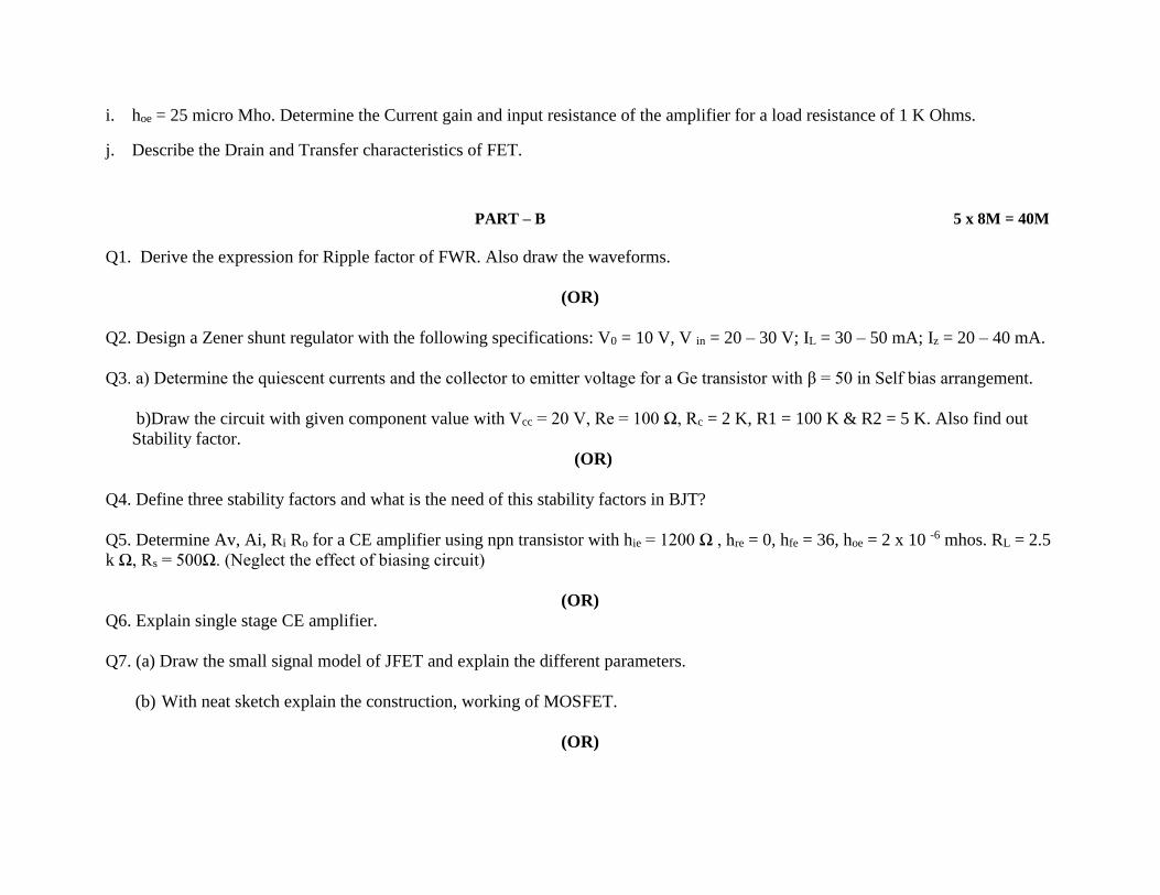
i. hoe = 25 micro Mho. Determine the Current gain and input resistance of the amplifier for a load resistance of 1 K Ohms.
j. Describe the Drain and Transfer characteristics of FET.
PART – B 5 x 8M = 40M
Q1. Derive the expression for Ripple factor of FWR. Also draw the waveforms.
(OR)
Q2. Design a Zener shunt regulator with the following specifications: V0 = 10 V, V in = 20 – 30 V; IL = 30 – 50 mA; Iz = 20 – 40 mA.
Q3. a) Determine the quiescent currents and the collector to emitter voltage for a Ge transistor with β = 50 in Self bias arrangement.
b)Draw the circuit with given component value with Vcc = 20 V, Re = 100 Ω, Rc = 2 K, R1 = 100 K & R2 = 5 K. Also find out
Stability factor.
(OR)
Q4. Define three stability factors and what is the need of this stability factors in BJT?
Q5. Determine Av, Ai, Ri Ro for a CE amplifier using npn transistor with hie = 1200 Ω , hre = 0, hfe = 36, hoe = 2 x 10 -6 mhos. RL = 2.5
k Ω, Rs = 500Ω. (Neglect the effect of biasing circuit)
(OR)
Q6. Explain single stage CE amplifier.
Q7. (a) Draw the small signal model of JFET and explain the different parameters.
(b) With neat sketch explain the construction, working of MOSFET.
(OR)

Q8. (a) Draw the characteristics of SCR and describe the different regions in it and their importance.
(b) Mention the advantages and disadvantages of LED and LCD.
Q9. Obtain the diode equation for current.
(OR)
Q10. What are the advantages of Voltage divider bias? Draw the circuit and explain the circuit operation.

VNR VIGNANA JYOTHI INSTITUTE OF ENGINEERING AND TECHNOLOGY
BACHUPALLY, NIZAMPET (S.O), HYDERABAD – 500090
LESSON PLAN: 2017-18
A Good Lesson Plan is instrumental for the delivery of course content in a competent way so that students get benefited in view
of learning, developing good skill set, updating with current trends in industry etc., Delivery including latest trends in the technology
and applications brings deep insight of the course in students. As the plan includes the home assignments, quizzes, course projects
etc., it carries out the continuous assessment of student learning (course outcomes).
The course delivery in adherence to the lesson plan is ensured through course level audit forms on regular basis.
II B. Tech : I Sem : EEE L T/P/D C
3 1 4
Course Name: PDE&CA Course Code: 5BS14
Names of the Faculty Member: Dr.Srinivas Joshi
Number of working days: 60
Number of Hours/week: 4
Total number of periods planned: 62
1. PREREQUISITES
Integral and Differential Calculus
2. COURSE OBJECTIVES
(Objectives define the importance of course and how the course is helpful to the students in their career.
Objectives must be defined first and contents must be developed later.)
The student should be able
• Computing Fourier coefficients.

• Understand the properties of Fourier transforms.
• Apply method of separation of variables to solve partial differential equations.
• Apply Cauchy’s theorem, Cauchy’s integral formula and residue theorem to evaluate complex intregation.
3. COURSE OUTCOMES (COs)
(Outcomes define what the student will be able to do upon completion of the course. Course outcomes must be
assessable. The blooms taxonomy terms are used as reference in defining course outcomes)
Upon completion of this course the student is able to
• Solve problems using Fourier series.
• Evaluate problems involving Fourier and inverse Fourier transforms.
• Solve the second order linear partial differential equations by method of separation of variables and Fourier series.
• Evaluate line and contour intregals.
4. MAPPING OF COs WITH POs
(This mapping represents the contribution of course in attaining the program outcomes and there by program
educational objectives. This also helps in strengthening the curriculum towards the improvement of program.)
Course
Outcomes
(COs)
Program Outcomes (POs)
a B c d E f g h i j K L
CO 1 3 3 2 1 2
CO 2 3 3 1 3 3
CO 3 2 3 2 2 2 3 2 2 2 3
3: High correlation, 2: Moderate correlation and 1: Low Correlation

5. LEARNING RESOURCES
(i) TEXT BOOKS
T1. Higher Engineering Mathematics – B. S. Grewal, Khanna publisher.
T2. Advance Engineering Mathematics - Peter O’Neil,(2000),5th Edition, Cengage Learning
T3. Schaum’s Outline Of Complex Variables - Murray.R.Spiegel,(2011), 2nd Edition, Tata McGraw Hill.
T4. Complex Variables & Its Applications- Churchill and Brown, (1996), International Edition, McGraw Hill.
(ii) REFERENCES (Publications/ Open Learning Resources)
(Course delivery including latest trends brings good insight of the course in students and also inculcates the habit of
self learning among the students.
Publications referred can be given unit wise or at course level.)
(a) Publications
PI. David Maslen ; Daniel N. Rockmore; Sarah Wolff “The Efficient Computation of Fourier Transforms on
Semisimple Algebras” pp 1–24, 11 July 2017
(b) Open Learning Resources for self learning
L1. http://nptel.ac.in/courses/117101055/18
L2. https://www.youtube.com/watch?v=gZNm7L96pfY
L3. https://www.mooc-list.com/tags/fourier
L4. www.mathworks.com/help/matlab/math/partial.
L5. www.youtube.com/watch?v=VBn1diQCykQ.

(iii) JOURNALS
J1. Journal Of Fourier Analysis and Applications
J2. Complex Analysis and Operator Theory
J3. Journal of Complex Analysis.
6. DELIVERY METHODOLOGIES
(Depending on the suitability to the delivery of concept, one or more among the following delivery methodologies
are adopted to engage the student in learning)
DM1: Chalk and Talk DM5: Open The Box
DM2: Learning by doing
DM3: Collaborative Learning (Think Pair Share, POGIL, etc.) DM6: Group Project
DM4: Demonstration (Physical / Laboratory / Audio Visuals)
7. PROPOSED FIELD VISITS/ GUEST LECTURE BY INDUSTRY EXPERT
(To be added for the courses as directed by the department.)
Guest Lecture: "Application of Fourier Series & Fourier Transforms in Engineerings" on
8. ASSESSMENT (As per Regulations, AM1 and AM2 are compulsory for assessment. Whereas, any two or more
assessment methodologies can be considered from AM3 to AM9 under assignment towards continuous assessment
of the performance of students.)
AM1: Semester End Examination . AM2: Mid Term Examination
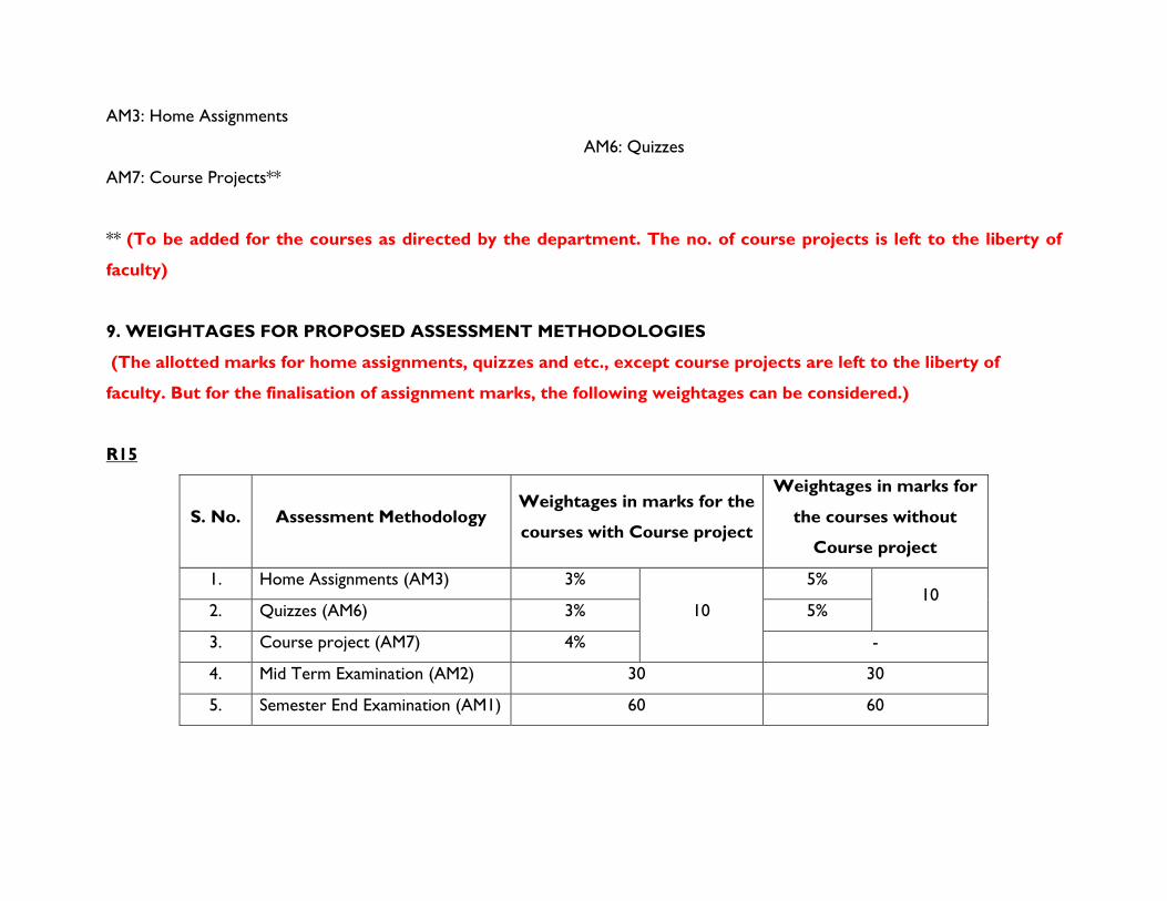
AM3: Home Assignments
AM6: Quizzes
AM7: Course Projects**
** (To be added for the courses as directed by the department. The no. of course projects is left to the liberty of
faculty)
9. WEIGHTAGES FOR PROPOSED ASSESSMENT METHODOLOGIES
(The allotted marks for home assignments, quizzes and etc., except course projects are left to the liberty of
faculty. But for the finalisation of assignment marks, the following weightages can be considered.)
R15
S. No. Assessment Methodology Weightages in marks for the
courses with Course project
Weightages in marks for
the courses without
Course project
1. Home Assignments (AM3) 3%
10
5% 10
2. Quizzes (AM6) 3% 5%
3. Course project (AM7) 4% -
4. Mid Term Examination (AM2) 30 30
5. Semester End Examination (AM1) 60 60

(i) HOME ASSIGNMENTS
On the beginning day of each unit, home assignment sheet is given to the students and the solution sheet for the same is expected
after two days of the completion of unit.
(ii) QUIZZES
Two quizzes are conducted in the course duration. One is scheduled on 29/08/2017 and the second one is scheduled on 04/11/2017.
10. SIMULATION SOFTWARES (If any)
7. MATLAB
8. MATHEMATICA
11. DETAILED COURSE DELIVERY PLAN
(Detailed syllabus mentioning its learning outcomes, teaching plan, tutorial questions and home assignment
questions for each unit can be given. Heads under teaching plan is given below. Model Academic plan can be taken
as reference.)
UNIT -I
Fourier series: Fourier series -- Fourier series of periodic functions, Euler’s formulae, Fourier series of even and odd functions having arbitrary periods, Half - range Fourier series. LEARNING OUTCOMES
After completion of this unit the student will be able to

• Express the function in terms of sine and cosine series in the given interval.
• Find the Fourier coefficients for a given function and express it in terms of sine/cosine series.
• Solve even and odd functions in terms of Fourier series.
• Evaluate the given function in terms of either half range Fourier sine series (or) cosine series.
TEACHING PLAN
S.
No. Contents of syllabus to be taught
No. of
Lecture
Periods
Lecture
Dates
Proposed Delivery
Methodologies
Learning Resources /
References
(Text Books /
Journals /
Publications/ Open
Learning Resources)
Course
Outcomes
118. Introduction and Applications of Fourier
series 1 5-07-17
DM1. Chalk and Talk (along
with PPT)
DM4. Demonstration of
one example.
T.1& T.2
L.3
CO 1
119.
Calculation of Euler’s coefficients.
1 6-07-17
DM1. Chalk and Talk
DM4. Detailed analysis with
the help of simulation
model
T.1 & T.2 CO 1

120. Problems on fourier series 1 7-07-17
DM1. Chalk and Talk
DM4. Detailed analysis with
the help of simulation
model
T.1 & T.2 CO 1
121. Points of discontinuity 1 7-07-17
DM1. Chalk and Talk
DM4. Detailed analysis with
the help of simulation
model
T.1, T.2 & L1 CO 1
122. Problems on discontinuity 1 12-07-17 DM1. Chalk and Talk. T.1& T.2 CO 1
123. Problems on even & odd function 1 13-07-17 DM1. Chalk and Talk. T.1& T.2 CO 1
124. Half range fourier series 1 14-07-17
DM1. Chalk and Talk
DM4. Detailed analysis with
the help of simulation
model
T.1 & T.2
L.3
CO 1

125. Problems 1 14-07-17
DM1. Chalk and Talk
DM4. Detailed analysis with
the help of simulation
model
T.1 & T.2 CO 1
126. Change of interval 1 19-07-17
DM1. Chalk and Talk
DM4. Detailed analysis with
the help of simulation
model
T.1& T.2 CO 1
127.
Problems on change of interval
1 20-07-17 DM1. Chalk and Talk T.1, T.2 & L.1 CO 1
TUTORIAL QUESTIONS
1.Write Dirichlet’s conditions for Fourier Expansion.
2. Find the Fourier series to represent the function −= xxxf ,sin)( .
3.Find the Fourier coefficient nb for the function f(x) = x.
4. Find half range cosine series for f(x) =
−
xforxlk
xforkx
2/)(
2/0
5. Expand 2)( 2 −= xxf as a Fourier series in the interval (-2,2).

UNIT- II
Fourier Transforms -- Fourier transform, Sine and Cosine transforms, properties and its applications.
LEARNING OUTCOMES
After completion of this unit the student will be able to
• Find Fourier transforms of given functions.
• Find Fourier sine and cosine transforms.
• Find finite Fourier sine/cosine transform in the given interval.
TEACHING PLAN
S.
No. Contents of syllabus to be taught
No. of
Lecture
Periods
Lecture
Dates
Proposed Delivery
Methodologies
Learning Resources /
References
(Text Books /
Journals /
Publications/ Open
Learning Resources)
Course
Outcomes
1)
Introduction to Fourier transforms. 1 9-08-17
DM1. Chalk and Talk
DM4. Detailed analysis with
the help of simulation
model.
T.1 & L.2 CO2

2) problems on Fourier sine/cosine intregal 1 10-08-17
DM1. Chalk and Talk
(along with PPT)
T.1 CO2
3) Fourier integral in complex form
Fourier sine/cosine transform 1 11-08-17
DM1. Chalk and Talk
(along with PPT)
DM3. Collaborative
Learning (Think Pair Share)
T.1& T.2 CO2
4) Properties of Fourier transforms
1 16-08-17 DM1. Chalk and Talk
T.1, T.2 &L2. CO2
5)
Problems on Fourier transform
1 17-08-17
DM1. Chalk and Talk
DM3. Collaborative
Learning (Think Pair Share)
T.1 & L.2 CO2
6)
Problems 1 18-08-17
DM1. Chalk and Talk
DM3. Collaborative
Learning (Think Pair Share)
T.1 & L.2 CO2
7) Problems on Inverse Fourier transform 1 19-08-17
DM1. Chalk and Talk
DM3. Collaborative
Learning (Think Pair Share)
T.1 & L.2 CO2
8) Problems on Fourier sine/cosine
transforms 1 21-08-17
DM1. Chalk and Talk
DM3. Collaborative
Learning (Think Pair Share)
T.1 & L.2 CO2

9) Problems 1 23-08-17
DM1. Chalk and Talk
DM3. Collaborative
Learning (Think Pair Share)
T.1 & L.2 CO2
10) Problems on inverse Fourier
sine/cosine transform 1 24-08-17
DM1. Chalk and Talk
DM3. Collaborative
Learning (Think Pair Share)
T.1 & L.2 CO2
11) Problems 1 25-08-17
DM1. Chalk and Talk
DM3. Collaborative
Learning (Think Pair Share)
T.1 & T.2 CO2
12) Finite fourier sine/cosine transforms 1 28-08-17
DM1. Chalk and Talk
DM3. Collaborative
Learning (Think Pair Share)
T.1 & T.2 CO2
13) Problems 1 30-08-17
DM1. Chalk and Talk
DM3. Collaborative
Learning (Think Pair Share)
T.1 & L.2 CO2
TUTORIAL QUESTIONS
1. Write Dirichlet’s conditions for Fourier transform.

2.If F(s) is the complex Fourier Transform of f(x), then prove that )())(( sFeaxfF isa=− .
3. Find the Fourier Transform of f(x) defined by
f(x) =
−
10
11 2
xfor
xforx hence evaluate
dxx
x
xxx)
2cos(
)sin()cos(
0
3
−
4. Find Fourier transform of f(x) defined by f(x) = 22 xae−
5. Find the Fourier sine transform ofx
exf
ax−
=)( .
UNIT- III
Standard Partial Differential Equations:
Method of seperation of variables, Applications: Problems of vibrating string- wave equation, Problems of one-dimensional heat equation,
Problems of steady state two dimensional heat flow-Laplace equation.
LEARNING OUTCOMES
After completion of this unit the student will be able to
• Solve the second order linear partial differential equations by method of separation of variables and Fourier series.
• Solve the first order wave equation by using the method of separation of variables and get the solution of wave equation.

• Find the solution of one dimensional heat equation in steady state and transient state.
• Solve Laplace equation by using the method of separation of variables.
TEACHING PLAN
S.
No. Contents of syllabus to be taught
No. of
Lecture
Periods
Lecture
Dates
Proposed Delivery
Methodologies
Learning Resources /
References
(Text Books /
Journals /
Publications/ Open
Learning Resources)
Course
Outcomes
1)
Introduction to partial differential
equations
1 21/07/17
DM1. Chalk and Talk
DM4. Detailed analysis with
the help of simulation
model
T.1, T.2 & L4 CO 3
2) Elimination of arbitrary functions &
arbitrary constants 1 21/07/17
Tutorial
DM1. Chalk and Talk T.1, T.2 CO 3
3) Method of separation of variables 1 24/07/17
DM1. Chalk and Talk
DM4. Detailed analysis with
the help of simulation
model
T.1 & T.2 CO 3

4) one dimensional wave equation 1 26/07/17
DM1. Chalk and Talk
DM4. Detailed analysis with
the help of simulation
model
T.1 & T.5 CO 3
5) Problems 1 27/07/17
Tutorial
DM3: Collaborative
Learning -Think Pair Share
T.1, T.2 CO 3
6) one dimensional heat flow equation 1 28/07/17
DM1. Chalk and Talk
DM4. Detailed analysis with
the help of simulation
model
T.1, T.2& L5 CO 3
7) Problems on steady state heat flow 1 31/07/17
DM1. Chalk and Talk
DM4. Detailed analysis with
the help of simulation
model
T.1, T.2 CO 3
8) Problems on heat flow equation 1 2/08/17
Tutorial
DM3: Collaborative
Learning -Think Pair Share
T.1, T.2 & L5 CO 3
9) Laplace equation 1 3/08/17 DM1. Chalk and Talk
T.1, T.2 & L5 CO 3

10) Problems 1 7/08/17
Tutorial
DM3: Collaborative
Learning -Think Pair Share
T.1, T.2 CO 3
11) Problems on all above topics
1 7/08/17
Tutorial
DM3: Collaborative
Learning -Think Pair Share
T.1, T.2 CO 3
TUTORIAL QUESTIONS
1. Write one dimensional heat conduction equation.
2. Solve 022 =
+
y
uy
x
ux
3. The bounding diameter of a semi-circular plate of radius ‘a’ cm is kept at 0°c and temperature along the semi circular boundary is given by
−
=
)2/()(50
)2/(0,50),(
when
whenaT Find the steady state temperature T(r, θ).
4. A tightly stretched string with fixed end points x=0 and x=l is initially in a position given by
=
l
xyy
3
0 sin . If it is released from rest from this
position, find the displacement y(x ,t).
5 .Find the solution of Laplace equation.
UNIT- IV
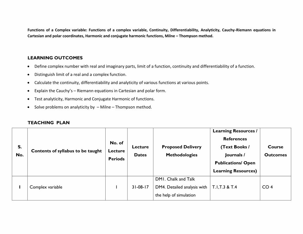
Functions of a Complex variable: Functions of a complex variable, Continuity, Differentiability, Analyticity, Cauchy-Riemann equations in
Cartesian and polar coordinates, Harmonic and conjugate harmonic functions, Milne – Thompson method.
LEARNING OUTCOMES
• Define complex number with real and imaginary parts, limit of a function, continuity and differentiability of a function.
• Distinguish limit of a real and a complex function.
• Calculate the continuity, differentiability and analyticity of various functions at various points.
• Explain the Cauchy’s – Riemann equations in Cartesian and polar form.
• Test analyticity, Harmonic and Conjugate Harmonic of functions.
• Solve problems on analyticity by – Milne – Thompson method.
TEACHING PLAN
S.
No. Contents of syllabus to be taught
No. of
Lecture
Periods
Lecture
Dates
Proposed Delivery
Methodologies
Learning Resources /
References
(Text Books /
Journals /
Publications/ Open
Learning Resources)
Course
Outcomes
1 Complex variable 1 31-08-17
DM1. Chalk and Talk
DM4. Detailed analysis with
the help of simulation
T.1,T.3 & T.4 CO 4

model
2 Analyticity. 1 01/09/17
DM1. Chalk and Talk
DM4. Detailed analysis with
the help of simulation
model
T.1,T.3 & T.4 CO 4
3 Cauchy- Riemann equations in
Cartesian form. 1 11/09/17
DM1. Chalk and Talk
DM4. Detailed analysis with
the help of simulation
model
T.1,T.3 & T.4 CO 4
4 C-R equations in polar form 1 13/09/17
Tutorial
DM3: Collaborative
Learning -Think Pair Share
T.1,T.3 & T.4 CO 4
5 Problems on analytic function 1 14/09/17
Tutorial
DM3: Collaborative
Learning -Think Pair Share
T.1,T.3 & T.4 CO 4
6 Harmonic and conjugate Harmonic
functions. 1 15/09/17
Tutorial
DM3: Collaborative
Learning -Think Pair Share
T.1,T.3 & T.4 CO 4
7 Milne Thompson Method 1 18/09/17 DM1.Power point
presentation. T.1,T.3 & T.4 CO 4
8 Problems on Milne Thompson method 1 18/09/17 DM1. Chalk and Talk T.1,T.3 & T.4 CO 4

9 Calculation of Harmonic functions
using Milne Thomson Method 1 20/09/17
DM1. Chalk and Talk
T.1,T.3 & T.4 CO 4
10 Problems 1 21/09/17 DM1. Chalk and Talk
T.1,T.3 & T.4 CO 4
TUTORIAL QUESTIONS
1.Derive C-R equations in polar form?
2.If a function is analytic, show that it is independent of z
3.Find the analytic function w= U+iV, if U= e-x [ (x2-y2)cos(y) + 2xy sin(y)]
4.If U and V are harmonic functions, show that Uy-Vx + i(Uy+Vx) is analytic function of z.
5.Show that 2
22 )()1()( zfuppu pp −−=
UNIT- V
Integration of Complex function, Power series and Residues:
Line integral, evaluation along a path and by indefinite integration. Cauchy’s integral theorem, Cauchy’s integral formula. Expansion of
Taylor’s series and Laurent series (without proofs). Singular point, Isolated singular point, pole of order m , essential singularity. Residues –
Evaluation of residue by formulae, Residue theorem, Evaluation of real integrals.

LEARNING OUTCOMES
After completion of this unit the student will be able to
• Define a Closed Curve , multiple curve, contour , simply connected region ,multiply connected region and Observe the properties of Integrals.
• Estimate the line Integral along a given path .
• Distinguish Cauchy’s integral theorem and Cauchy’s integral formula.
• Apply Cauchy’s Integral theorem to find the integral of a closed cur.
• Recognize Sequence , Infinite series , power series,region of convergence of a series.
• Describe Taylor’s Series Maclaurin’s series and Laurent series
• Apply Taylor’s Series and Laurent series to expand the function.
• Explain Singular point –Isolated singular point, essential singularity and pole.
• Calculate Residues by formulae and by Laurent series.
• Evaluate real integrals by contour integration.
TEACHING PLAN
S.
No. Contents of syllabus to be taught
No. of
Lecture
Periods
Lecture
Dates
Proposed Delivery
Methodologies
Learning Resources /
References
(Text Books /
Journals /
Publications/ Open
Learning Resources)
Course
Outcomes

1) Complex Integration: Line Integral 1 21/09/17
DM1. Chalk and Talk
DM4. Detailed analysis with
the help of simulation
model
DM3: Collaborative
Learning -Think Pair Share.
T.1,T.3 & T.4 CO 4
2) Cauchy’s theorem 1 22/09/17
DM1. Chalk and Talk
Tutorial
DM3: Collaborative
Learning -Think Pair Share
T.1,T.3 & T.4 CO 4
3) Problems on Cauchy’s Theorem 1 27/09/17
DM1. Chalk and Talk
Tutorial
DM3: Collaborative
Learning -Think Pair Share
T.1,T.3 & T.4 CO 4
4) Cauchy’s integral formula 1 4/10/17 DM3: Collaborative
Learning -Think Pair Share T.1,T.3 & T.4 CO 4
5) Problems on Cauchy’s integral formula 1 5/10/17 DM1. Chalk and Talk
Tutorial T.1,T.3 & T.4 CO 4
6) Expansion in Taylor’s series 1 6/10/17
DM1. Chalk and Talk
DM3. Collaborative
Learning (Think Pair Share)
T.1,T.3 & T.4 CO 4

7) Laurent series 1 9/10/17
DM1. Chalk and Talk
DM3. Collaborative
Learning (Think Pair Share)
T.1,T.3 & T.4 CO 4
8 Problems on expansions 1 11/10/17
DM1. Chalk and Talk
DM3. Collaborative
Learning (Think Pair Share)
T.1,T.3 & T.4 CO 4
9 Singular point, Isolated singular
point,essential singularity 1 12/10/17
DM1. Chalk and Talk
DM3: Collaborative
Learning -Think Pair Share
T.1,T.3 & T.4 CO 4
10 Poles of different orders 1 13/10/17 DM1. Chalk and Talk
T.1,T.3 & T.4 CO 4
11 Residue formula 1 16/10/17
DM1. Chalk and Talk
DM3. Collaborative
Learning (Think Pair Share)
T.1,T.3 & T.4 CO 4
12 Problems on residues 1 18/10/17
DM1. Chalk and Talk
DM3. Collaborative
Learning (Think Pair Share)
T.1,T.3 & T.4 CO 4
13 Evaluation of residues by residue
formula 1 20/10/17
DM1. Chalk and Talk
DM3. Collaborative
Learning (Think Pair Share)
T.1,T.3 & T.4 CO 4

14 Residue theorem 1 23/10/17
DM1. Chalk and Talk
DM4. Detailed analysis with
the help of simulation
model
T.1,T.3 & T.4 CO 4
15 Problems on residue theorem 1 26/10/17
DM1. Chalk and Talk
DM3. Collaborative
Learning (Think Pair Share)
T.1,T.3 & T.4 CO 4
16 Evaluation of integrals using Residues 1 27/10/17
DM1. Chalk and Talk
DM3. Collaborative
Learning (Think Pair Share)
T.1,T.3 & T.4 CO 4
17 Problems 1 02/11/17
DM1. Chalk and Talk
DM3. Collaborative
Learning (Think Pair Share)
T.1,T.3 & T.4 CO 4
18 Problems 1 03/11/17
DM1. Chalk and Talk
DM3. Collaborative
Learning (Think Pair Share)
T.1,T.3 & T.4 CO 4
TUTORIAL QUESTIONS
1. Find the Residues of 1
)(2 +
=z
zzf at each pole.

2. Find the Laurents series expansion of the function: )2)(3)(1(
162
+−−
−−
zzz
zz in the region 23 + z 5 .
3. Show by the method of residues, )0(5cos53
0
=+ ba
d
by contour integration in the complex plane.
4. Evaluate
+0
222 )(
cosdx
ax
mx.
HOME ASSIGNMENT-I
Issue date: 22/07/2017 Submission date: 28/08/2017
a) 1. Express 2)( xxf = as half – Range sine series in 20 x
b) Express 2)( xxxf −= as Fourier series in the interval − x
c) Find the Fourier Transform of = − xexxf x 0,)(
d) Find the Fourier cosine transform of f(x)=
−
2,0
21,2
10,
x
xx
xx
e) Find F.T of (a) f(x) =
−
10
11 2
xfor
xforx hence evaluate dx
x
x
xxx)
2cos(
)sin()cos(
0
3
−
HOME ASSIGNMENT-II
Issue date: 9 /10/2017 Submission date: 21/10/2017
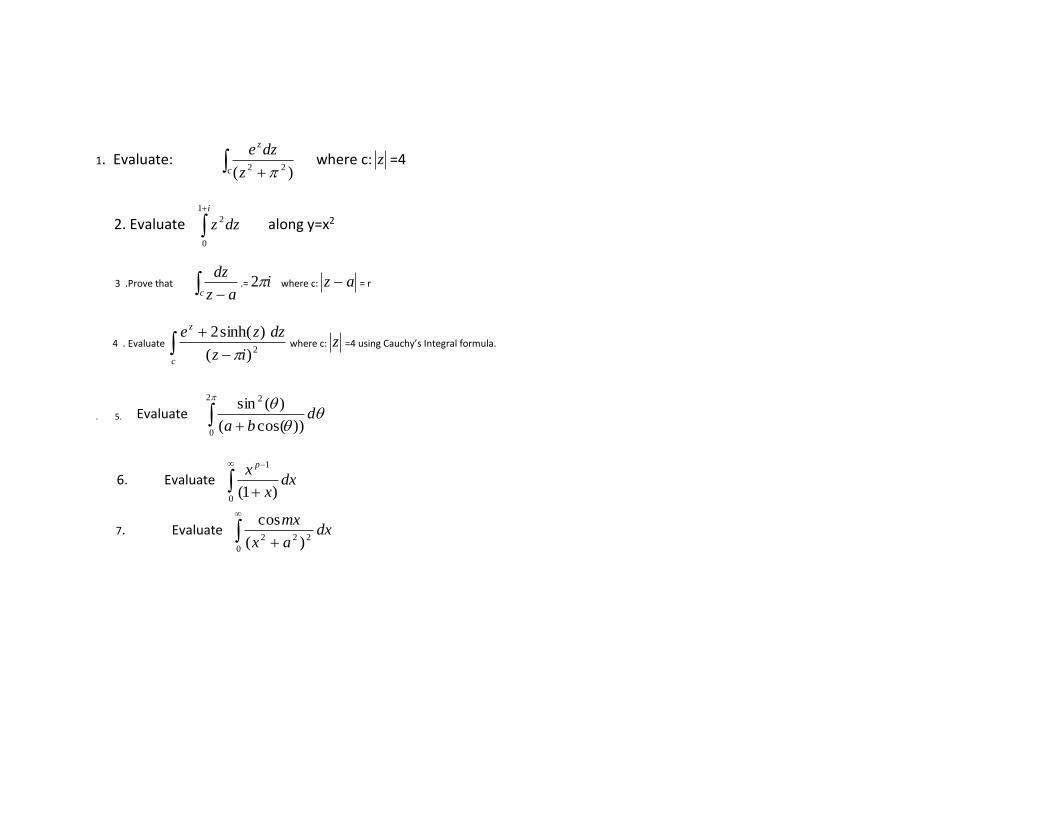
1. Evaluate: +c
z
z
dze
)( 22 where c: z =4
2. Evaluate +i
dzz
1
0
2 along y=x2
3 .Prove that −c az
dz.= i2 where c: az − = r
4 . Evaluate −
+
c
z
iz
dzze2)(
)sinh(2
where c: z =4 using Cauchy’s Integral formula.
. 5. Evaluate +
2
0
2
))cos((
)(sind
ba
6. Evaluate −
+0
1
)1(dx
x
x p
7. Evaluate
+0
222 )(
cosdx
ax
mx

12. MODEL QUESTION PAPER
VNR VIGNANA JYOTHI INSTITUTE OF ENGINEERING & TECHNOLOGY
(AN AUTONOMOUS INSTITUTE)
II B.TECH. I SEMESTER REGULAR EXAMINATION-2017
SUBJECT: PDE WITH APPLICATIONS & COMPLEX ANALYSIS (MECHANICAL & AME)
Time: 3 Hours Max. Marks: 60
------------------------------------------------------------------------------------------------------------------------------------------------------------------
PART-A
1. Answer the following 10×2 =20 Marks
a) Define periodic function with an example.
b) Find the Fourier coefficient 0a for the function −= xinxxf )( .
c) Write Dirichlet’s conditions for Fourier transform.
d) If F(s) is the complex Fourier Transform of f(x), then prove that )())(( sFeaxfF isa=− .
e) Find all possible solutions of Uxx+Uyy=0 using variable separable method?
f) Find the solution of one dimensional wave equation.
g) Write Cauchy-Riemann equations in polar form?
h) Verify whether u(x,y)= ex.cos(y) is harmonic (or) not.
i) Evaluate dzz
zz
C
−
+−
1
12
where C:|z|=1
Subject Code
5BS14
R15

j) Find the residue at poles of)1(
)(3
34
zz
zzzf
−
+= ?
PART- B 5x8 = 40 Marks
UNIT- I
1) Obtain the Fourier series expansion of f(x)= |x| in (- π, π) and hence deduce that ..............5
1
3
1
1
1
8 222
2
+++=
.
(or)
2) Find the Fourier series of f(x)=
−
xx
x
0,sin
0,0 ; hence show that )2(
4
1............
75
1
53
1
31
1−=+
•+
•+
• .
UNIT- II
3) Find the Fourier transform of ( ) )2/( 2xexf −= , -< x < .
(or)
4) Find the Fourier transform of f(x) =
−
10
11 2
xfor
xforx hence evaluate dx
x
x
xxx)
2cos(
)sin()cos(
0
3
−
UNIT- III

5) The bounding diameter of a semi-circular plate of radius ‘a’ cm is kept at 0°c and temperature along the semi circular
boundary is given by
−
=
)2/()(50
)2/(0,50),(
when
whenaT Find the steady state temperature T(r, θ).
(or)
6) A tightly stretched string with fixed end points x=0 and x=l is initially in a position given by
=
l
xyy
3
0 sin . If it is released from
rest from this position, find the displacement y(x ,t).
UNIT- IV
7. a) If f(z)=u+iv is an analytic function and u-v= ex(cos(y)- sin(y)) find f(z) in terms of f(z).
b) Find the orthogonal trajectories of the family of curves: x4+y4-6x2y2 = C
(or)
8) Evaluate ++
+
C
dzzz
z
52
42
where c is the circle (i) 1=z (ii) 21 =−+ iz (iii) 21 =++ iz using Cauchy’s integral formula.

UNIT- V
9) Evaluate by the method of residues +
2
0cosba
d
(or)
10)Evaluate
0,0))(( 2222
2
++
−
badxbxax
x

VNR VIGNANA JYOTHI INSTITUTE OF ENGINEERING AND TECHNOLOGY
BACHUPALLY, NIZAMPET (S.O), HYDERABAD – 500090
LESSON PLAN: 2017-18
A Good Lesson Plan is instrumental for the delivery of course content in a competent way so that students get benefited in view
of learning, developing good skill set, updating with current trends in industry etc., Delivery including latest trends in the technology
and applications brings deep insight of the course in students. As the plan includes the home assignments, quizzes, course projects
etc., it carries out the continuous assessment of student learning (course outcomes).
The course delivery in adherence to the lesson plan is ensured through course level audit forms on regular basis.
II B. Tech : I Sem : EEE-1 L T/P/D C
4 1 4
Course Name: Electrical Machines-1 Course Code: 5EE004
Names of the Faculty
Member: Dr J Viswanatha Rao / Dr.V.Madhusudhan
Number of working days: 90
Number of Hours/week: 5
Total number of periods
planned: 65
1. PREREQUISITES
Circuit Theory (5EE01)
2. COURSE OBJECTIVES
(Objectives define the importance of course and how the course is helpful to the students in their career.
Objectives must be defined first and contents must be developed later.)
• To understand the Electro-mechanical Energy conversion
• To know the construction and operation of DC machines

• To know the different testing methods for dc machines
• To know the behavior of DC machines
• To learn about different speed and voltage control methods
3. COURSE OUTCOMES (COs)
(Outcomes define what the student will be able to do upon completion of the course. Course outcomes must be
assessable. The blooms taxonomy terms are used as reference in defining course outcomes)
After completion of this course the student is able to
CO-1• Identify the different parts of a dc machine and their roles in its operation.
CO-2• Carry out different testing methods to predetermine the efficiency of DC machines
CO-3• Select a DC machine for particular practical application
CO-4• Start and to control voltage and speed of DC machines
4. MAPPING OF COs WITH POs
(This mapping represents the contribution of course in attaining the program outcomes and there by program
educational objectives. This also helps in strengthening the curriculum towards the improvement of program.)
Course
Outcomes
(COs)
Program Outcomes (POs)
a b c d e f g h i j k l
CO 1 2 1 1
1
1
2 2
CO 2 3 3 2
3 2
1 1 1 3 3
CO 3 2 3 2 2 2 3 2 2 2 1 3 3

CO4 2 3
1
2 1
2
3: High correlation, 2: Moderate correlation and 1: Low Correlation
5. LEARNING RESOURCES
(i) TEXT BOOKS
T1. Electric Machines by P.S.Bimbra khanna publishers
T2. Electrical Machiney A.E.Fitzgerald,C.Kingsly and S.Umans,Mc Graw-Hill-5th edition.
T3. Electric Machines by I.J Nagrath & D.P.Kothari, Tata Mc Graw – Hill Publishers
T4. Fundamentals of Electrical machines by Chapman Tata Mc Graw – Hill Publishers
T5. Electrical Technology vol-II B.L.Thereja & A.K.Thereja
T6. Performance and Design of D.C machines by Clayton and Hancock, BPB publishers
T7. Electrical machines by Gordon.R.Slemon, Alan straughen, Addison – Wesley.co.,1980, 1st edition
(ii) REFERENCES (Publications/ Open Learning Resources)
(Course delivery including latest trends brings good insight of the course in students and also inculcates the habit of
self learning among the students.
Publications referred can be given unit wise or at course level.)
(a) Publications
[P1] Z. Zhang, Y. Yan, Y. Tao, “A new topology of low speed doubly salient brushless DC generator for wind power generation,”
IEEE Transactions on Magnetics, vol. 48, pp. 1227-1233, March 2012.
[P2] L. Yu, Z. Zhang, Z. Chen, et al, “Analysis and verification of the doubly salient brushless DC generator for automobile auxiliary
power unit application,” IEEE Transactions on Industrial Electronics, vol. 61, pp. 6655-6663, December 2014.

[P3] Y. Wang, Z. Zhang, L. Yu, et al, “Investigation of a variable-speed operating doubly salient brushless generator for automobile
on-board generation application,” IEEE Transactions on Magnetics, vol. 51, pp.1-4, November 2015.
[P4] W. Dai, H. Qin, H. Guo, et al, “Analysis of commutation in three-phase rectifier of doubly salient electro-magnetic generator,”
Proceedings of the CSEE, vol. 28, pp. 111-117, 2008.
[P5] I. Somos, “Commutation and destructive oscillation in diode circuits,”Transactions of the American Institute of Electrical
Engineers, vol. 80,pp. 162-172, May 1961.
[P6] E. E. VonZastrow and J. H. Galloway, “Commutation behavior of diffused high-current rectifier diodes,” IEEE Transactions on
Industry and General Applications, vol. IGA-1, pp. 157-166, March 1965.
[P7] J. Lutz, H. Schlangenotto, U. Scheuermann, and R. D. Doncker, Semiconductor Power Devices, Physics, Characteristics,
Reliability.Berlin Heidelberg: Springer-Verlag, 2011, pp. 188-191.
[P8] J. Millan, P. Godignon, X. Perpina, et al, “A survey of wide bandgap power semiconductor devices,” IEEE Transactions on
Power Electronics, vol. 29, pp. 2155-2163, May 2014.
(b) Open Learning Resources for self learning
L1. http://nptel.ac.in/courses/108105017/
L2. https://ocw.mit.edu/courses/electrical-engineering-and-computer-science/6-685-electric-machines-fall-2013/index.htm
L3. https://www.coursera.org/learn/electric-machines
L4: http://www.plexim.com/academy/electric-machines
(iii) JOURNALS
J1. IEEE Industrial Electronics Society
J2 IEEE Industry Applications Society.
J3. IEEE Power & Energy Society.
6. DELIVERY METHODOLOGIES

(Depending on the suitability to the delivery of concept, one or more among the following delivery methodologies
are adopted to engage the student in learning)
DM1: Chalk and Talk
DM2: PPT
DM3: Collaborative Learning (Think Pair Share, etc.)
DM4: Demonstration (Physical / Laboratory / Audio Visuals/Video Visuals)
7. PROPOSED FIELD VISITS/ GUEST LECTURE BY INDUSTRY EXPERT
(To be added for the courses as directed by the department.)
Guest Lecture: "Application of Electrical Mahcines in Renewable Energy Systems" by Mr. B. Raju, Assit Divisional Engineer, TSCPL
polancha Khammam(DIST) is scheduled on 14/09/2017
8. ASSESSMENT
(As per Regulations, AM1 and AM2 are compulsory for assessment. Whereas, any two or more assessment
methodologies can be considered from AM3 to AM9 under assignment towards continuous assessment of the
performance of students.)
AM1: Semester End Examination . AM2: Mid Term Examination
AM3: Home Assignments
AM6: Quizzes
AM7: Course Projects**
** (To be added for the courses as directed by the department. The no. of course projects is left to the liberty of
faculty)
9. WEIGHTAGES FOR PROPOSED ASSESSMENT METHODOLOGIES

(The allotted marks for home assignments, quizzes and etc., except course projects are left to the liberty of
faculty. But for the finalisation of assignment marks, the following weightages can be considered.)
R15
S. No. Assessment Methodology Weightages in marks for the
courses with Course project
Weightages in marks for
the courses without
Course project
1. Home Assignments (AM3) 3%
10
5% 10
2. Quizzes (AM6) 3% 5%
3. Course project (AM7) 4% -
4. Mid Term Examination (AM2) 30 30
5. Semester End Examination (AM1) 60 60
(i) HOME ASSIGNMENTS
On the beginning day of each unit, home assignment sheet is given to the students and the solution sheet for the same is expected
after two days of the completion of unit.
(ii) QUIZZES
Two quizzes are conducted in the course duration. One is scheduled on 29/08/2017 and the second one is scheduled on 04/11/2017.
(iii) COURSE PROJECTS
One course project is assigned to each project batch of size three in the beginning of the course and assessed at the end of the course.
One midterm evaluation is carried out to monitor the progress of the project and the team coherence.
1) Development of small DC Generator.

2) DC Motor speed controller based on PC
3) DC brush less Motor
4) Mobile charger by using DC Generator
5) Vacuum cleaner using DC Motor
6) Design of PM Generator for A Vertical Axis Wind Turbine
10. SIMULATION SOFTWARES (If any)
9. MATLAB
11. DETAILED COURSE DELIVERY PLAN
(Detailed syllabus mentioning its learning outcomes, teaching plan, tutorial questions and home assignment
questions for each unit can be given. Heads under teaching plan is given below. Model Academic plan can be taken
as reference.)
UNIT-I
ELECTROMECHANICAL ENERGY CONVERSION
Law of energy conservation- Need of Electromechanical energy Conversion-Definition of Generator and Motor-Coupling medium-
Role-Energy balance equation of a motor and generator-Singly excited electromagnetic systems-Energy-Co-energy- force expression-
Multi excited systems-Torque expression-Problems
UNIT-II
D.C GENERATORS (PART –I)
D.C generator-principle-simple loop generator-Construction- DC Armature Windings-Lap and Wave windings-Development-
Differences- emf equation-Classification of D.C.Generators -self excitation-open circuit characteristics-critical resistance and critical
speed problems.
UNIT-III
D.C.GENERATORS (PART –II)
Armature Reaction-Effects-Distribution of Field mmf and Armature mmf-Demagnetising and Cross magnetizing AT/pole-
Compensating Windings-Problems-Commutation-Methods of Improving Commutation-Generator Characteristics-Power Stages-
Losses-Efficiency-Parallel Operation-Problems
UNIT-IV
D.C.MOTORS (PART –I)
D.C.Motor-Principle-Function of Commutator-Types-Back emf-Voltage Equation-Mechanical Power developed-Condition for
maximum mechanical power developed-Torque equation-Motor characteristics-Power stages- Efficiency-Condition for maximum
efficiency-problems.
UNIT-V
DC MOTORS (PART –II)
Speed control-Field and Armature control methods - starting of D.C.Motors-3 point and 4 point starters-Design of starter steps-
problems-Testing of D.C.Machines: Brake Test, Swin-Burne’s Test, Hopkinson’sTest, Field’s Test and Retardation Test, Problems,
concept of Electrical Braking [Elementary Treatment only].
LEARNING OUTCOMES
After completion of this unit the student will be able to
5. Analyze the operating principles of electro magnetic energy conversion.
6. Understand the construction and operating characteristics of DC Machines.
7. Apply the voltage and speed control methodologies for various types of DC Machine Testing.
8. Evaluate the applications of DC Machines.
TEACHING PLAN

S.
No.
No. of
Lecture
Periods
Lecture
Dates
Proposed
Delivery
Methodologies
Contents of
syllabus to be
taught
Learning
Resources /
References
(Text Books
/ Journals /
Publications/
Open
Learning
Resources)
Course
Outcomes
1.
Unit -1
ELECTROMECHANICAL ENERGY CONVERSION
Introduction to SI Units, Electro mechanical Energy conversion.
1/2 03-07-17
DM1. Chalk and
Talk.
DM2: PPT
L.1.
T.1& T.2
CO 1, 2, 3
2.
Motor and Generator Action coupling medium
2/1 04-07-17/
05-07-17
DM1. Chalk and
Talk
DM2: PPT
L.1.
T.1 & T.2 CO 1 & CO 3
3.
Forces and torque in magnetic field systems
Energy balance equation 1
05-07-17/
07-07-17
DM1. Chalk and
Talk
T.1 & T.2 CO 1 & CO 3
4.
Concept of energy stored in magnetic field system
1 06-07-17/
08-07-17
DM1. Chalk and
Talk
T.1 & T.2 CO 1 & CO 3

5.
singly excited system filed energy –co- energy 2/1
18-07-17/
10-07-17
DM1. Chalk and
Talk. T.1 & T.2 CO 1 & CO 3
6.
Force torque equation derivation
1 18-07-17/
12-07-17
DM1. Chalk and
Talk
T.1 & T.2 CO 1 & CO 3
7.
Estimated magnetic force in linear
systems.
1 20-07-17/
14-07-17
DM1. Chalk and
Talk
T.1 & T.3 CO 1 & CO 3
8.
Introduction of doubly excited system
1 24-07-17/
15-07-17
DM1. Chalk and
Talk T.1 & T.3 CO 1 & CO 3
9.
Force and torque derivation
2 25-07-17/
19-07-17
DM1. Chalk and
Talk
T.1 & T.2 CO 1 & CO 3
10.
Unit-2 D.C.Generators-I (PART –I)
Introduction of DC generators and
principle
2/1 26-07-17/
21-07-17
DM1. Chalk and
Talk
DM2: PPT
L.1.
T.1 & T.2 CO 1 & CO 3

11.
Working and construction of DC generator
1 27/07/17/
24-07-17
DM1. Chalk and
Talk
DM2: PPT
L.1.
T.1 & T.2 CO 1 & CO 3
12.
Construction of DC machines
1/2 31/07/17/
26-07-17
DM1. Chalk and
Talk
DM2: PPT
T.1 & T.3 CO 1 & CO 3
13.
Introduction o f Armature windings- lap and wave windings
2 01/08/17/
28-07-17
DM1. Chalk and
Talk
DM2: PPT
L.1.
T.1 & T.2 CO 1 & CO 3
14.
Problems related with lap and wave windings
2/1
02/08/17/
31/07/17
DM1. Chalk and
Talk
T.1 & T.2 CO 1 & CO 3
15.
Problems related with lap and wave windings 1/2
03/08/17/
02/08/17
DM1. Chalk and
Talk
L.1.
T.1 & T.2 CO 1 & CO 3
16.
EMF equation of DC machines and problems 1 07/08/17
DM1. Chalk and
Talk
T.1 & T.3 CO 1 & CO 2
17.
Classification of DC machines
2 08/08/17/
09/08/17
DM1. Chalk and
Talk
DM2: PPT
L.1.
T.1 & T.2 CO 1 & CO 2

18.
Problems in DC machines
1 10/08/17/
11/08/17
DM1. Chalk and
Talk
T.1 & T.3 CO 1 & CO 3
19.
Tutorial
1 11/08/17/
12/08/17
Tutorial
DM3:
Collaborative
Learning -Think
Pair Share
T.1 & T.2 CO 1 & CO 3
20.
Characteristics of DC Generators
2 16/08/17
DM1. Chalk and
Talk
DM2: PPT
T.1 & T.2 CO 2, 3 & 4
21.
Problems on OCC
1 21/08/17/
18/08/17
DM1. Chalk and
Talk
T.1 & T.3 CO 2 & CO 3
22.
Load characteristics of different types of machines
2 22/08/17/
21/08/17
DM1. Chalk and
Talk
DM2: PPT
T.1 & T.3 CO 2 & CO 3
23.
Problems & Revision of Second unit
1 23/08/17/
26/08/17
DM1. Chalk and
Talk
T.1 & T.3 CO 1 & CO 3
24.
nit-III
D.C.GENERATORS
(PART –II)
1 24/08/17/ 28/08/17
DM1. Chalk and
Talk
DM2: PPT
L.1. T.1 & T.2
CO 2, 3 & 4

Introduction of Armature Reaction
25.
Armature Reaction and its effects of machine
1/2 28/08/17/
30/08/17
DM1. Chalk and
Talk
DM2: PPT
T.1 & T.3 CO 2 & CO 3
26.
Demagnitizing and cross magnetizing AT/Pole
2 29/08/17/
12/09/17
DM1. Chalk and
Talk
DM2: PPT
T.1 & T.3 CO 2 & CO 3
27.
remedial measures for Armature reaction
1 30/08/17/
16/09/17
DM1. Chalk and
Talk
DM2: PPT
L.1.
T.1 & T.2 CO 2 & CO 3
28.
Methods of Compensating Armature reaction
2/1 12/09/17/
18/09/17
DM1. Chalk and
Talk
DM2: PPT
T.1 & T.3 CO 2, 3 & 4
29.
Process of commutation & classification
2 13/09/17/
22/09/17
DM1. Chalk and
Talk
T.1 & T.3 CO 2 & CO 3
30.
Reactance voltage method and Improving commutation 1
18/09/17/
25/09/17
DM1. Chalk and
Talk
T.1 & T.3 CO 2 & CO 3
31.
Power stages and Power Loss
1 19/09/17/
26/09/17
DM1. Chalk and
Talk
T.1 & T.3 CO 2 & CO 3

32.
Condition for maximum efficiency
1/2 21/09/17/
27/09/17
DM1. Chalk and
Talk
T.1 & T.3 CO 2 & CO 3
33.
Problem on Efficiency Calculation
1
25/09/17/
06/10/17
DM1. Chalk and
Talk
T.1 & T.3 CO 2 & CO 3
34.
Condition for Parallel operation and Operation of shunt generators 1
26/09/17/
07/10/17
DM1. Chalk and
Talk
T.1 & T.3 CO 2 & CO 3
35.
Load sharing problem on Parallel operation 1
27/09/17/
09/10/17
DM1. Chalk and
Talk
T.1 & T.3 CO 2 & CO 3
36.
Revision of unit-3
11/10/17
DM1. Chalk and
Talk
T.1 & T.3 CO 2 & CO 3
37.
Unit-4 D.C.Motors –I
Part-1
Introduction of DC motors 1
04/10/17/
11/10/17
DM1. Chalk and
Talk
DM2: PPT
T.1 & T.3 CO 2 & CO 3
38.
Back emf – torque equation
1 05/10/17/
13/10/17
DM1. Chalk and
Talk
T.1 & T.3 CO 2 & CO 3
39. Function of commutator armature
torque Shaft torque
1 09/10/17/
14/10/17
DM1. Chalk and
Talk
T.1 & T.3 CO 2 & CO 3
40.
Problems
2 10/10/17/
16/10/17
DM1. Chalk and
Talk
T.1 & T.3 CO 2 & CO 3
41.
Mechanical Power developed and power stages 1
11/10/17/
20/10/17
DM1. Chalk and
Talk
T.1 & T.3 CO 2 & CO 3

42.
Speed torque characteristics-applications of DC motors.
1 12/10/17/
21/10/17
DM1. Chalk and
Talk
DM2: PPT
T.1 & T.3 CO 2, 3 & 4
43.
Characteristics of shunt motors
1 16/10/17/
23/10/17
DM1. Chalk and
Talk
T.1 & T.3 CO 2, 3 & 4
44.
Characteristics of series and compound motors 2
17/10/17/
25/10/17
DM1. Chalk and
Talk
T.1 & T.3 CO 2, 3 & 4
45.
Condition for Maximum Efficiency Losses and efficiency 1
19/10/17/
27/10/17
DM1. Chalk and
Talk
T.1 & T.3 CO 2, 3 & 4
46.
Tutorial
1 23/10/17/
28/10/17
Tutorial
DM3:
Collaborative
Learning -Think
Pair Share
T.1 & T.3 CO 2, 3 & 4
47.
Tutorial
2/1 24/10/17/
30/10/17
Tutorial
DM3:
Collaborative
Learning -Think
Pair Share
T.1 & T.3 CO 2, 3 & 4
48.
Revision of unit-4
1 25/10/17/
30/10/17
DM1. Chalk and
Talk
T.1 & T.3 CO 2, 3 & 4
49.
Unit-5 Speed control and Testing of D.C.Machines
Introduction 1
26/10/17/
01/11/17
DM1. Chalk and
Talk
T.1 & T.3 CO 2, 3 & 4

50.
Speed control of dc motors – Armature voltage and field flux control methods 1
30/10/17/
01/11/17
DM1. Chalk and
Talk
T.1 & T.3 CO 2, 3 & 4
51.
Starting by 3 point and 4point starter
2 31/10/17/
03/11/17
DM1. Chalk and
Talk
T.1 & T.3 CO 2, 3 & 4
52.
Design of starter steps
1 01/11/17/
04/11/17
DM1. Chalk and
Talk
T.1 & T.3 CO 2, 3 & 4
53.
Testing of dc machines- brake test- Swinburne’s test 1
01/11/17/
04/11/17
DM1. Chalk and
Talk
T.1 & T.3 CO 2, 3 & 4
54.
Principles of regenerative or Hopkinson’s test 1 06/11/17
DM1. Chalk and
Talk
T.1 & T.3 CO 2, 3 & 4
55.
Retardation test- separation of losses.
1 07/11/17/
06/11/17
DM1. Chalk and
Talk
T.1 & T.3 CO 2, 3 & 4
56.
Methods of Electrical braking:
1/2 08/11/17
DM1. Chalk and
Talk
T.1 & T.3 CO 2, 3 & 4
57.
plugging, dynamic and regenerative
1 09/11/17/
---------
DM1. Chalk and
Talk
T.1 & T.3 CO 2, 3 & 4
TUTORIAL QUESTIONS
1. An 8-pole D.C generator has per pole flux of 40 mwb and winding is connected in lap with 960 conductors. Calculate the
generated EMF on open circuit when it runs at 400 rpm. If the armature is wave wound at what speed must the machine be
driven to generate the same voltage.
2. Draw the winding table for a 4-pole wave connected armature having 30 coil sides and give a developed diagram of the
winding showing the polarity and position of brushes the main poles and the direction of motion for a D.C motor.

3. The OCC of a D.C shunt generator for a speed of 1000 rpm is given by the following table:
Field Current I 8(A) 2 3 4 5 6 7
Generated e.m.f (V) 102 150 185 215 232 245
The shunt circuit has resistance of 37 ohm Find the speed at which the recitation may be respected to build up. The Ra is 0.04
ohm. Neglecting the effect of brush drop and armature reactance, estimate the terminal voltage when the speed is 1000 rpm
and the armature delivery a current of 100 A.
4. A 22.38 KW, 400V, 2-pole wave wound DC shunt motor has 840 Armature conductors and 140 commutator segments. Its full-
load efficiency is 88% and the shunt field current is 1.57 A. If brushes are shifted backward through 1.5 segments from the
geometrical natural axis. Find the demagnetizing and distorting AT/Pole.
5. Two d.c compound generations A and B with an equalizing bar, supply a total load of 500 A. The data relating to the machine
are as follows.
Arm resistance RA = 0.05 ohm, RB = 0.03 ohm
Series field wdg RSA = 0.02 ohm, RsB= 0.01 ohm
Generated emf EA = 463 V, EB = 470 V
Calculate
a. The armature current in each machine
b. The current in each series winding
c. The current in the equalizing bar and
d. The bus bar voltage
6. The load characteristics of two shunt generations are as follows
M-I 0 283 566 850
M-II 0 200 400 600
Voltage 500 490 480 470

If the above machine works in parallel to supply a total load of 400 KW, determine
a. The load taken by each machine and
b. The amount by which the open circuit emf of the machine must be raised by field regulation so that the two machines share
the 400 KW load equally
HOME ASSIGNMENT-I
Issue Date:21-08-2017
Submission Date:28-08-2017
1.Explain the constructional details of D.C Machine with neat sketches of all parts
2.a) Derive an expression for induced E.M.F from the first principles (Dynamically induced E.M.F)
b) An 8-pole D.C generator has per pole flux of 40 mwb and winding is connected in lap with 960 conductors. Calculate the
generated EMF on open circuit when it runs at 400 rpm. If the armature is wave wound at what speed must the machine be
driven to generate the same voltage.
3. Draw the winding table for a 4-pole wave connected armature having 30 coil sides and give a developed diagram of the winding
showing the polarity and position of brushes the main poles and the direction of motion for a D.C motor.
4. Explain the concept of voltage build-up in self excited D.C generators and also explain the significance of critical field
resistance and critical speed and also list out factors for failure of voltage build-up and suggest some remedial measures
9. The OCC of a D.C shunt generator for a speed of 1000 rpm is given by the following table:
Field Current I 8(A) 2 3 4 5 6 7
Generated e.m.f (V) 102 150 185 215 232 245
The shunt circuit has resistance of 37 ohm Find the speed at which the recitation may be respected to build up. The Ra is 0.04
ohm. Neglecting the effect of brush drop and armature reactance, estimate the terminal voltage when the speed is 1000 rpm
and the armature delivery a current of 100 A.
HOME ASSIGNMENT-II
Issue date: 24/10/2017 Submission date: 31/10/2017
1. a) Explain the concept of commutator function in D.C motor and derive the expression for torque and explain about shaft,
armature
b) Draw and explain the characteristics of D.C motor
2. A Shunt motor operating on 230V takes armature current of 6A at NL and runs at 1200 rpm take Ra = 0.25 ohm. Find the speed
and electromagnetic torque when the armature takes 36 A with the same flux.
3. A 4-pole 250V D.C shunt motor has lap connected 960 conductions. The flux per pole is20 mwb. Determine the torque
developed by the armature and the useful torque in N-m when current drawn By the motor is 32A. The armature resistance is 0.1ohm
and shunt field resistance is 125 ohm. The Rotational losses of the machine amount to 825 W. Derive the formula used.
4.. a) Explain why armature is called constant torque method and field control is known as constant power control
b) Explain the necessities and working of 3-point starter with a neat sketch
5. a) Explain about Series-Parallel speed control of D.C series motors
b) A 500 V, D.C shunt motor takes a current of 5A on NL. The resistances of the armature and the field circuits are 0.22 ohm and 250
ohm respectively. Find i) The efficiency when loaded and taking a current of 100 A
ii) The percentage change in speed state precisely the assumptions made

12. MODEL QUESTION PAPER
VNR VIGNANA JYOTHI INSTITUTE OF ENGINEERING & TECHNOLOGY
(AN AUTONOMOUS INSTITUTE)
II B.TECH. I SEMESTER REGULAR EXAMINATION-2017
SUBJECT: ELECTRICAL MACHINES-1 (EEE)
Time: 3 Hours Max. Marks: 60
-------------------------------------------------------------------------------------------------------------------------------
PART-A
1. Answer the following 2×10 =20 Marks
xi. What is electromagnetic energy conversion?
xii. What is energy balance equation?
xiii. Define principle of operation of d.c generator?
xiv. Explain back pitch & front pitch in armature winding?
xv. Define armature reaction?
xvi. What is function of commutator?
xvii. What is the function of interpoles in DC machines?
xviii. Define principle of operation of d.c motor?
xix. What are the methods of speed control of DC motors?
xx. What are the application of DC Motors?
Part-B
Subject Code
5EEE04
R15

Answer the following questions 5×8=40 Marks
UNIT I
1. (a) Describe the principle of energy conversion? (4M) CO 1
(b) Explain Fleming’s left hand and right hand rules? (4M) CO 1
(OR)
2. Describe singly and doubly excited magnetic systems. (8M) CO 1
UNIT II
3. Explain the constructional details of D.C Machine with neat sketches of all parts. (8M) CO 2
(OR)
4. a) Derive an expression for induced E.M.F of DC Generator (4M) CO 2
b) An 8-pole D.C generator has per pole flux of 40 mwb and winding is connected in lap with 960 conductors. Calculate the
generated EMF on open circuit when it runs at 400 rpm. If the armature is wave wound at what speed must the machine be driven
to generate the same voltage. (4M) CO 2
UNIT III
5. a). Explain the concept of Armature Reaction and Commutation effects in D.C Generator and suggest some remedies for
improving further effects. (4M) CO 2
b) Derive the expressions for demagnetizing and cross magnetizing ampere turns. (4M) CO 2
(OR)
6. a) A 22.38 KW, 400V, 2-pole wave wound DC shunt motor has 840 Armature conductors and 140 commutator segments. Its full-
load efficiency is 88% and the shunt field current is 1.57 A. If brushes are shifted backward through 1.5 segments from the
geometrical natural axis. Find the demagnetizing and distorting AT/Pole. (8M)
CO 2

UNIT IV
7. a) Explain the concept of commutator function in D.C motor and derive the expression for armature torque (4M)
b). A Shunt motor operating on 230V takes armature current of 6A at NL and runs at 1200 rpm take Ra = 0.25 ohm. Find the speed
and electromagnetic torque when the armature takes 36 A with the same flux.(4M)
OR
8. a)A 4-pole 250V D.C shunt motor has lap connected 960 conductions. The flux per pole is20 mwb. Determine the torque
developed by the armature and the useful torque in N-m when current drawn By the motor is 32A. The armature resistance is
0.1ohm and shunt field resistance is 125 ohm. The Rotational losses of the machine amount to 825 W.(4M)
b) Derive the formula used.(4M)
UNIT V
9 . a) Explain the necessities and working of 3-point starter with a neat sketch(4M)
b) Explain speed control of D.C series motors (4M)
OR
10) A 500 V, D.C shunt motor takes a current of 5A on NL. The resistances of the armature and the field circuits are 0.22 ohm and
250 ohm respectively.
Find i) The efficiency when loaded and taking a current of 100 A (4M)
ii) The percentage change in speed state precisely the assumptions made(4M)

VNR VIGNANA JYOTHI INSTITUTE OF ENGINEERING AND TECHNOLOGY
BACHUPALLY, NIZAMPET (S.O), HYDERABAD – 500090
LESSON PLAN: 2017-18
A Good Lesson Plan is instrumental for the delivery of course content in a competent way so that students get benefited in view
of learning, developing good skill set, updating with current trends in industry etc., Delivery including latest trends in the technology
and applications brings deep insight of the course in students. As the plan includes the home assignments, quizzes, course projects
etc., it carries out the continuous assessment of student learning (course outcomes).
The course delivery in adherence to the lesson plan is ensured through course level audit forms on regular basis.
II B. Tech : I Sem : EEE-1& II L T/P/D C
3 0 3
Course Name: Switching Theory and Logic Design Course Code: 5EC03
Names of the Faculty Member: G.Lakshminarayana and CH. Sunil Chowdary
Number of working days: 90
Number of Hours/week: 5
Total number of periods planned: 77
1. PREREQUISITES
Basic Electronics
2. COURSE OBJECTIVES
(Objectives define the importance of course and how the course is helpful to the students in their career.
Objectives must be defined first and contents must be developed later.)
The student should be able

• To understand the concepts of number systems, codes and design of various combinational and
synchronous sequential circuits
• To learn various methods to minimize the Boolean expressions for reducing the number of gates and cost
• To realize logic networks, digital computers using PROM, PLA, PAL devices.
• To design state machines and ASM charts
3. COURSE OUTCOMES (COs)
(Outcomes define what the student will be able to do upon completion of the course. Course outcomes must be
assessable. The blooms taxonomy terms are used as reference in defining course outcomes)
Upon completion of this course the student is able to
1. Represent Digital data in various formats
2. Design and implement combinational and sequential circuits with minimized logic
3. Design ASM charts for digital systems
4. MAPPING OF COs WITH POs
(This mapping represents the contribution of course in attaining the program outcomes and there by program
educational objectives. This also helps in strengthening the curriculum towards the improvement of program.)
Course
Outcomes
(COs)
Program Outcomes (POs)
a b c d e f g h i j k l
CO 1 3 3 3 2 3 1
3 2
3
CO 2 3
3 2 2 1 1 1
2
CO 3 3 2 2 3 3 2 2
2 1 1 2
3: High correlation, 2: Moderate correlation and 1: Low Correlation
5. LEARNING RESOURCES

(i) TEXT BOOKS
T1. Switching & Finite Automata theory – Zvi Kohavi, TMH,2nd Edition.
T2. Digital Design – Morris Mano, PHI, 3rd Edition, 2006.
T3. An Engineering Approach To Digital Design – Fletcher, PHI. Digital Logic –Application and Design – John M. Yarbrough,
Thomson.
T4. Fundamentals of Logic Design – Charles H. Roth, Thomson Publications, 5th Edition, 2004.
T5. Digital Logic Applications and Design – John M. Yarbrough, Thomson Publications, 2006.
T6. Modern Digital Electronics by R.P JAIN, TMH.
(ii) REFERENCES (Publications/ Open Learning Resources)
(Course delivery including latest trends brings good insight of the course in students and also inculcates the habit of
self learning among the students.
Publications referred can be given unit wise or at course level.)
(a) Publications
Unit II
P1. H. Troy Nagle, Jr., B. D. Carroll, And J. David Irwin A Book Review On “An Introduction To Computer Logic “ Ieee
Transactions Prentice Hall, 1975, 529 Pp.,
P2. George H. Mealy The Bell System Technical Journal On “A Method For Synthesizing Sequential Circuits” Nokia
Bell Labs Journal Pages: 1045 – 1079
P3. Franz E. Hohn; L. Robert Schissler The Bell System Technical Journal “ Boolean Matrices And The Design
Of Combinational Relay Switching Circuits” Nokia Bell Labs Journal Pages: 177 – 202.

P4. T. C. Bartee, Review Editor R. Alonso, D. C. Englebart, D. L. Epley, R. A. Laing, M. Lewin, J. H. Pomerene
“Reviews Of Books And Papers In The Computer Field” Ire Transactions On Electronic Computers Pages 295-303.
(b) Open Learning Resources for self learning
L1. http:// http://nptel.ac.in/courses/117103064/
L2. https://www.coursera.org/courses?languages=en&query=digital+circuits
(iii) JOURNALS
J1. IEEE Switching and Automata Theory
J2. IEEE Switching Circuit Theory and Logical Design
J3. IEEE Journal on Circuit Theory and Design
6. DELIVERY METHODOLOGIES
(Depending on the suitability to the delivery of concept, one or more among the following delivery methodologies
are adopted to engage the student in learning)
DM1: Chalk and Talk DM2: PPT DM5: Open The Box
DM3: Collaborative Learning (Think Pair Share, POGIL, etc.) DM7: Group Project
DM4: Demonstration (Physical / Laboratory / Audio Visuals)

7. PROPOSED FIELD VISITS/ GUEST LECTURE BY INDUSTRY EXPERT
(To be added for the courses as directed by the department.)
Guest Lecture: "Design and development of logical circuits different processors is scheduled on 17/08/2017
(And / Or)
Field Visit: As a part of class, field visit is scheduled to Vision-Tek industry on 25/10/2017.
8. ASSESSMENT
(As per Regulations, AM1 and AM2 are compulsory for assessment. Whereas, any two or more assessment
methodologies can be considered from AM3 to AM9 under assignment towards continuous assessment of the
performance of students.)
AM1: Semester End Examination . AM2: Mid Term Examination
AM3: Home Assignments
AM6: Quizzes
AM7: Course Projects**
** (To be added for the courses as directed by the department. The no. of course projects is left to the liberty of
faculty)
9. WEIGHTAGES FOR PROPOSED ASSESSMENT METHODOLOGIES
(The allotted marks for home assignments, quizzes and etc., except course projects are left to the liberty of
faculty. But for the finalisation of assignment marks, the following weightages can be considered.)
R15

S. No. Assessment Methodology Weightages in marks for the
courses with Course project
Weightages in marks for
the courses without
Course project
1. Home Assignments (AM3) 3%
10
5% 10
2. Quizzes (AM6) 3% 5%
3. Course project (AM7) 4% -
4. Mid Term Examination (AM2) 30 30
5. Semester End Examination (AM1) 60 60
(i) HOME ASSIGNMENTS
On the beginning day of each unit, home assignment sheet is given to the students and the solution sheet for the same is expected
after two days of the completion of unit.
(ii) QUIZZES
Two quizzes are conducted in the course duration. One is scheduled on 24/08/2017 and the second one is scheduled on 02/11/2017.
(iii) COURSE PROJECTS
One course project is assigned to each project batch of size three in the beginning of the course and assessed at the end of the
course. One midterm evaluation is carried out to monitor the progress of the project and the team coherence.
1. Arduino based Home Automation
2. Auto Metro Train to Shuttle between Stations
3. Density Based Auto Traffic Signal Control with Android Based Remote Override
10. SIMULATION SOFTWARES (If any)
10. P-Spice

11. MATLAB
11. DETAILED COURSE DELIVERY PLAN
(Detailed syllabus mentioning its learning outcomes, teaching plan, tutorial questions and home assignment
questions for each unit can be given. Heads under teaching plan is given below. Model Academic plan can be taken
as reference.)
UNIT- I
NUMBER SYSTEMS & CODES:
Philosophy of number systems – complement representation of negative numbers-binary arithmetic-binary codes-error detecting &
error correcting codes –Hamming codes.
BOOLEAN ALGEBRA:
Fundamental postulates of Boolean algebra - Basic theorems and properties
Learning Outcomes
After completion of this unit the student will be able to
1. Convert decimal numbers into binary, octal, hexadecimal numbers.
2. Conversion from binary to decimal, octal & hexadecimal numbers.
3. Can add or subtract or divide or multiply binary numbers.
4. Able to convert binary code to gray code and vice-versa.
5. Able to write excess-3 code to any decimal digit.
6. Can be able to detect an error and correct the error.
7. Can simplify the given functions using known properties

8. Will be able to prove the given expressions.
TEACHING PLAN
S.
No. Contents of syllabus to be taught
No. of Lecture
Periods
Lecture
Dates
Proposed
Delivery
Methodologies
Learning Resources
/ References
(Text Books /
Journals /
Publications/ Open
Learning Resources)
Course
Outcomes
1 Introduction to number representation 01 03-07-17
DM1. Chalk and
Talk.
DM2: PPT
L.1.
T.1& T.2 CO 1
2 Philosophy of number systems 01 04-07-17
DM1. Chalk and
Talk.
DM2: PPT
L.1.
T.1& T.2 CO 1
3 Complement representation of
negative numbers. 01 05-07-17
DM1. Chalk and
Talk.
DM2: PPT T.1& T.2 CO 1
4 Binary Arithmetic. 01 06-07-17
DM1. Chalk and
Talk.
DM2: PPT T.1& T.2
CO 1 & CO
2
5 Binary Codes – Weighted codes, Non
weighted Codes. 02 18-07-17
DM1. Chalk and
Talk.
DM2: PPT T.1& T.2
CO 1 & CO
2
6 Error detection codes. 02 18-07-17 DM1. Chalk and T.1& T.2 CO 1 & CO

Talk.
DM2: PPT
2
7 Error correction codes – Hamming
code. 02 20-07-17
DM1. Chalk and
Talk.
DM2: PPT T.1& T.2
CO 1 & CO
2
8 Fundamental postulates of Boolean
algebra. 01 24-07-17 DM1. Chalk and
Talk. T.1& T.2
CO 1 & CO
2
9 Basic properties 01 25-07-17
DM1. Chalk and
Talk
DM4.
Demonstration of
one example.
T.1& T.2 CO 1 & CO
2
10 Switching expressions. 01 26-07-17
DM1. Chalk and
Talk
DM4.
Demonstration of
one example.
T.1& T.2 CO 2 & CO
3
11 De Morgan’s Theorem. 01 27/07/17
DM1. Chalk and
Talk
DM4.
Demonstration of one example.
T.1& T.2 CO 2 & CO
3
12 Numericals 02 31/07/17
DM1. Chalk and
Talk
DM4. Demonstration of
one example.
T.1& T.2 CO 2 & CO
3

UNIT-II
SWITCHING FUNCTIONS
Canonical and Standard forms - Algebraic simplification, Digital logic gates, properties of XOR gates –universal gates-Multilevel
NAND/NOR realizations.
MINIMIZATION OF SWITCHING FUNCTIONS
Map method, Prime implicates, don’t care combinations, Minimal SOP and POS forms, Tabular Method, Prime –Implicate chart,
simplification rules.
Learning Outcomes
After completion of this unit the student will be able to
1. Can draw the Karnaugh maps for 3-variable, 4-variable, and 5-variable maps.
2. Can simplify the given functions.
3. Will be able to differentiate between Sum Of Products and Products Of Sums.
4. They can also simplify the functions using Tabular Method.
5. Can draw gate networks for the obtained simplified functions.
TEACHING PLAN
S.
No.
Contents of syllabus to be
taught
No. of
Lecture
Periods
Lecture
Dates
Proposed
Delivery
Methodologies
Learning
Resources /
References
(Text Books /
Course
Outcomes

Journals /
Publications/
Open Learning
Resources)
1 Switching functions – Conical forms 02
01/08/17
DM1. Chalk and
Talk
DM2: PPT
L.1.
T.1 & T.2 CO 1 & CO 3
2 Logic gates (AND, OR, NOT) 01 02/08/17
DM1. Chalk and
Talk T.1 & T.2 CO 1 & CO 3
3 Exclusive – OR gate (Introduction &
properties)
01 03/08/17
DM1. Chalk and
Talk
T.1 & T.2 CO 2 & CO 3
4 NAND and NOR gates. 02 07/08/17
DM1. Chalk and
Talk T.1 & T.3 CO 2 & CO 3
5 Karnaugh map representation (3-
variable, 4-variable, and 5-variable
maps
02
08/08/17
DM1. Chalk and
Talk
DM2: PPT
T.1 & T.2 CO 2 & CO 3
6 Simplification of Logic expressions
using K- Map
02 10/08/17
DM1. Chalk and
Talk T.1 & T.3 CO 2 & CO 3
7 Don’t care combinations 01 11/08/17
DM1. Chalk and
Talk
T.1 & T.2 CO 2 & CO 3
8 Prime implicates 01 16/08/17
DM1. Chalk and
Talk T.1 & T.2 CO 2 & CO 3
9 Tabular Method 02 21/08/17
DM1. Chalk and
Talk
L.1.
T.1 & T.2 CO 2 & CO 3
10 Prime implicates chart. 01 22/08/17
DM1. Chalk and
Talk T.1 & T.3 CO 2 & CO 3
11 Numericals 02 23/08/17
DM1. Chalk and
T.1 & T.2 CO 2 & CO 3

Talk
DM4.
Demonstration of
one example.
UNIT III
COMBINATIONAL LOGIC DESIGN
Design using conventional logic gates, Encoder, Decoder, Multiplexer, De-Multiplexer, Modular design using IC chips, MUX
Realization of switching functions Parity bit generator, Code-converters, Hazards and hazard free realizations.
Learning Outcomes
After completion of this unit the student will be able to
1. Explain the concept of combinational circuits
2. Designing of adder, sub tractor, serial adder, parallel adder using logic gates.
3. Concept of encoded & decoder, Designing of encoded & decoder using NAND & NOR gates
4. Explain the applications of Encoder & Decoder
5. Explain MUX & DEMUX
6. Design MUX & DEMUX using IC’S.
7. Explain the Realization of MUX switching functions
8. Design parity bit generator.
9. Design Code converters for BCD – Binary.
10. Explain Hazards & Hazards free Realizations.
11. Designing of PLD – ROM, RAM, PAL and PLA.
12. Different types of memories, designing of ROM.
13. Design of PAL and PLA

14. Using PLD’s design PLD realizations of switching functions.
TEACHING PLAN
S.
No. Contents of syllabus to be taught
No. of
Lecture
Periods
Lecture Dates
Proposed
Delivery
Methodologies
Learning
Resources /
References
(Text Books /
Journals /
Publications/
Open Learning
Resources)
Course
Outcomes
1 Designing using conventional logic gates 01
24/08/17
DM1. Chalk and
Talk
T.1 & T.3 CO 2 & CO 3
2 Encoder, Decoder. 02
28/08/17
DM1. Chalk and
Talk
DM2: PPT
T.1 & T.3 CO 2 & CO 3
3 Multiplexer, De-Multiplexer. 02
29/08/17
DM1. Chalk and
Talk
DM2: PPT
L.1.
T.1 & T.2 CO 2 & CO 3
4 Modular design using IC chips 01
30/08/17
DM1. Chalk and
Talk
DM2: PPT
T.1 & T.3 CO 2 & CO 3

5 MUX realization of switching functions 02
12/09/17
DM1. Chalk and
Talk
DM2: PPT
T.1 & T.3 CO 2 & CO 3
6 Parity bit generator 01
13/09/17
DM1. Chalk and
Talk
DM2: PPT
T.1 & T.2 CO 2 & CO 3
7 Code-converters 02
18/09/17
DM1. Chalk and
Talk
T.1 & T.3 CO 2 & CO 3
8 Hazards and Hazard free Realizations 01
19/09/17
DM1. Chalk and
Talk
T.1 & T.3 CO 2 & CO 3
9 Half adder and Full adder 01
21/09/17
DM1. Chalk and
Talk
T.1 & T.2 CO 2 & CO 3
10 Half subtractor and Full subtractor 01
25/09/17
DM1. Chalk and
Talk
T.1 & T.2 CO 2 & CO 3
UNIT-IV
SEQUENTIAL CIRCUITS – I
Classification of sequential circuits (Synchronous, Asynchronous, Pulse mode, Level mode with examples) Basic flip-flops-Triggering
and excitation tables. Steps in synchronous sequential circuit design. Design of modulo-N Ring & Shift counters, Serial binary adder,
sequence detector.

Learning Outcomes
After completion of this unit the student will be able to
1. Classify the different types of sequential circuits.
2. Explain Synchronous, Asynchronous, Pulse mode and Level mode with examples.
3. Explain various Flip-flops.
4. Explain Triggering and Excitation Tables.
5. Explain the various steps involved in synchronous sequential circuits design.
6. Design a modulo – N ring counter.
7. Design a modulo – N ring shift counter.
8. Design a binary serial adder.
9. Design a sequential decoder.
TEACHING PLAN
S.
No. Contents of syllabus to be taught
No. of
Lecture
Periods
Lecture
Dates
Proposed
Delivery
Methodologies
Learning
Resources /
References
(Text Books /
Journals /
Publications/
Open
Learning
Resources)
Course
Outcomes
1 Classification of sequential circuits. 01
26/09/17
DM1. Chalk and
Talk
DM2: PPT T.2 & T.3 CO1 & CO 3
2 Synchronous, Asynchronous 02 27/09/17
DM1. Chalk and
Talk T.2 & T.3 CO 2 & CO 3

3 Pulse mode, Level mode 01
04/10/17
DM1. Chalk and
Talk
DM2: PPT T.2 & T.3 CO 2 & CO 3
4 Basic flip-flops 02 05/10/17
DM1. Chalk and
Talk T.2 & T.3 CO 1 & CO 3
5 Triggering and excitation tables 01
09/10/17
DM1. Chalk and
Talk
DM2: PPT T.2 & T.3 CO 2 & CO 3
6 Synchronous sequential circuit design 02
10/10/17
DM1. Chalk and
Talk
T.2 & T.3 CO 2 & CO 3
7 Modulo-N Ring & Shift counters. 02
11/10/17
DM1. Chalk and
Talk
DM2: PPT T.2 & T.3 CO 2 & CO 3
8 Serial binary adder 01
12/10/17
DM1. Chalk and
Talk
T.1 & T.3 CO 2 & CO 3
9 sequence detector 01
16/10/17
DM1. Chalk and Talk
DM2: PPT T.1 & T.3 CO 2 & CO 3
10 Numericals 02 17/10/17
DM1. Chalk and
Talk T.1 & T.3
CO 2 & CO 3
Unit –V
SEQUENTIAL CIRCUITS – II
Finite state machine-capabilities and limitations, Mealy and Moore models-minimization of completely specified and incompletely
specified sequential machines, Partition techniques and Merger chart methods-concept of minimal cover table. Introduction to ASM
charts, simple examples, system Design using data path and control subsystems, ASM charts for Flip Flops and Binary multiplier.
Learning Outcomes
After completion of this unit the student will be able to
1. Explain the Finite State Machine Capabilities.
2. Explain the Finite State Machine limitations.
3. Design a Mealy machine.
4. Design a Moore machine.
5. Minimization of sequential machines.
6. Explain the concept of minimal cover table.
7. Explain the different types of Merger chart methods.
8. Explain the Salient features of the ASM chart with examples.
9. Explain the control implementations.
10. Explain the System design using data path and control subsystems.
11. Give the examples of Weighing machine and binary multiplier.
TEACHING PLAN
S.
No. Contents of syllabus to be taught
No. of
Lecture
Periods
Lecture
Dates
Proposed
Delivery
Methodologies
Learning
Resources /
References
(Text
Books /
Journals /
Publication
Course
Outcomes
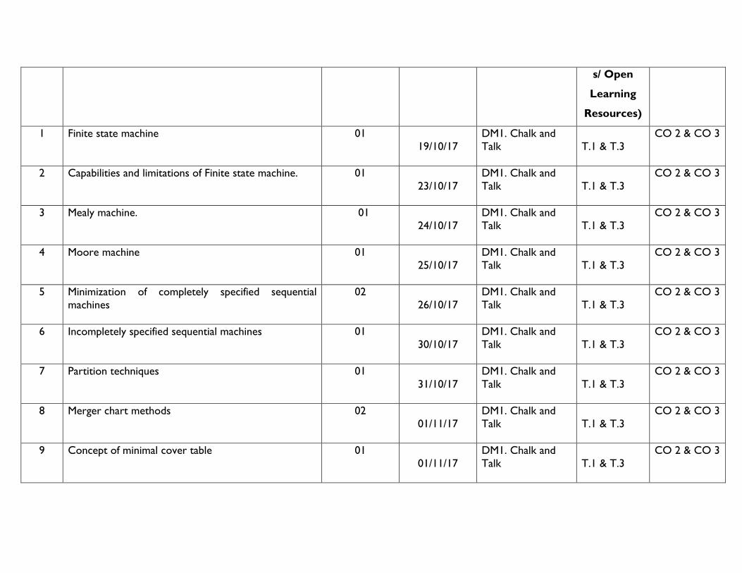
s/ Open
Learning
Resources)
1 Finite state machine 01
19/10/17
DM1. Chalk and
Talk
T.1 & T.3
CO 2 & CO 3
2 Capabilities and limitations of Finite state machine. 01
23/10/17
DM1. Chalk and
Talk
T.1 & T.3
CO 2 & CO 3
3 Mealy machine. 01
24/10/17
DM1. Chalk and
Talk
T.1 & T.3
CO 2 & CO 3
4 Moore machine 01
25/10/17
DM1. Chalk and
Talk
T.1 & T.3
CO 2 & CO 3
5 Minimization of completely specified sequential
machines
02
26/10/17
DM1. Chalk and
Talk
T.1 & T.3
CO 2 & CO 3
6 Incompletely specified sequential machines 01
30/10/17
DM1. Chalk and
Talk
T.1 & T.3
CO 2 & CO 3
7 Partition techniques 01
31/10/17
DM1. Chalk and
Talk
T.1 & T.3
CO 2 & CO 3
8 Merger chart methods 02
01/11/17
DM1. Chalk and
Talk
T.1 & T.3
CO 2 & CO 3
9 Concept of minimal cover table 01
01/11/17
DM1. Chalk and
Talk
T.1 & T.3
CO 2 & CO 3

10
ASM charts, Salient features of ASM charts
Examples of ASM charts.
01
06/11/17
DM1. Chalk and
Talk
T.1 & T.3
CO 2 & CO 3
11 System designing using data path and control
subsystems
02
07/11/17
DM1. Chalk and
Talk
T.1 & T.3
CO 2 & CO 3
12 Control implementations 01
08/11/17
DM1. Chalk and
Talk T.1 & T.3
CO 2 & CO 3
13 Examples of weighing machine and Binary multiplier. 01
09/11/17
DM1. Chalk and
Talk T.1 & T.3
CO 2 & CO 3
TUTORIAL QUESTIONS
1. Convert (23A4.EC) H to Decimal.
2. Divide (110101.11) 2 by (101) 2.
3. Convert the following into Gray number.
i) (3A7) H ii) (527) 8
4. Reduce A’B+A’BC’+A’BCD+A’BC’D’E
5. Reduce the expression f=∑m (2,3,6,7,8,10,11,13,14) using K-map
6. Minimize the following expression f=∑m (0,1,2,8,9,15,17,21,24,25,27,31).
7. Simplify the following Boolean function for minimal POS form using K-map and implement using NOR gates.
F(W,X,Y,Z) = π M (4,5,6,7,8,12) . d (1,2,3,9,11,14)

8. Realize the Boolean function T(X,Y,Z) = (1,3,4,5) using logic gates for hazard free.
Determine a minimal state table equivalent to the state table given using the partition technique.
PS NS,Z
X=0 X=1
S1
S2
S3
S4
S5
S6
S7
S1,1
S1,1
S2,0
S1,0
S4,1
S2,0
S4,1
S1,0
S6,1
S5,0
S7,0
S3,1
S5,0
S3,1
HOME ASSIGNMENT-I

Issue date: 22/08/2017 Submission date: 28/08/2017
1. a) Convert A0F9.0EB into decimal, binary and octal systems.
b) Add -45.75 to +87.5 using 12-bit 1’s and 2’s compliments.
2. a) Discuss the classification of binary codes and importance.
b) Perform 679.6 - 885.9 decimal subtraction in BCD by 9’s complement method.
3. Explain the all logic gates with neat circuit diagrams and truth tables.
4. a) Reduce using mapping the expression f= Π M(2,8,9,10,11,12,14,) in SOP and POS forms.
b) Write the minterms and maxterms of 5 variable k – map.
5. a) Realize the all logic gates operations using NAND gate.
b) Expand A+BC1+ABD1+ABCD to standard SOP and POS forms.
HOME ASSIGNMENT-II
Issue date: 22/10/2017 Submission date: 28/10/2017
1. (a)Implement Ful l Adder using decoder and OR gates.
(b) Realize the Boolean function T(X,Y,Z) = Σ(1,3,4,5) using logic gates for
hazard free.
2. Design a 64 line output de-multiplexer using lower order de-multiplexer such as 4 to 16 line and 2 to 4 line de-multiplexers.
3. Explain the working of 3-bit bi-directional shift register with the help of diagram.

4. Design mod-9 asynchronous counter using D flip flop.
5. Explain the following related to sequential circuits with suitable examples.
(a) State diagram
(b) State table
(c) State assignment.
12. MODEL QUESTION PAPER
VNR VIGNANA JYOTHI INSTITUTE OF ENGINEERING & TECHNOLOGY
(AN AUTONOMOUS INSTITUTE)
II B.TECH. I SEMESTER REGULAR EXAMINATION-2017
SUBJECT: SWITCHING THEORY AND LOGIC DESIGN
(EEE)
Time: 3 Hours Max. Marks: 60
------------------------------------------------------------------------------------------------------------------------------------------------------------------
PART-A
1. Answer the following 2×10 =20 Marks
i. Represent decimal number 6027 in BCD CO1
ii. Convert (198)12 to decimal. CO1
iii. Define ASM Charts. CO3
iv. Write the truth table for AND logic gate. CO2
v. What is data selector. CO2
vi. Reduce the following Boolean expressions (AB + AC) CO2
vii. What the 7-bit hamming code requires. CO1
Subject Code
5EC03
3
R15

viii. Why the flip-flops are used. CO2
ix. What is the Gray code? CO1
x. State control subsystems. CO3
Part-B
Answer the following questions 5×8=40 Marks
UNIT I
1. a. What is the Gray code? What are the rules to construct Gray code? CO1 c. List the XS3 code for decimal 0 to 9. (4M+4M)
(OR)
2. Explain the all logic gates with neat circuit diagrams and truth tables. CO 1
UNIT II
3. ) Obtain the real minimal expression for f=Ʃ m(1,2,4,6,7) using k-map in SOP and POS forms.
b) Discuss the prime implicants, essential PI, Reduntant PI and Selective PI with examples. CO 2
(OR)
4. Simplify the following Boolean expressions using K-map and implement them using NOR gates: (a) F (A, B, C, D) = AB’C’ + AC + A’CD’
(b) F (W, X, Y, Z) = W’X’Y’Z’ + WXY’Z’ + W’X’YZ + WXYZ. CO 2
UNIT III
5. a. Discuss the working of a BCD adder.
b. Explain the 3 to 8 line decoder with the help of a logic diagram and truth table. CO 2

(OR)
6. a. Explain the full subtractor with neat diagrams.
b. Distinguish between multiplexer and demultiplexer with examples. CO2
UNIT IV
7. (a) Draw the logic diagram of a 4 bit binary ripple counter using Positive edge triggering. CO2
(b) Draw the block diagram of a 4 - bit serial adder and explain its Operation.
(OR)
8. Design a modulo-8 counter which counts in the way specified below. Use JK flip-flops in your realization. CO2
UNIT V
9. Discuss the Finite state machine-capabilities and limitations CO 3
(OR)
10. Explain the operation of Mealy and Moore models with neat diagrams. CO 3

VNR VIGNANA JYOTHI INSTIYUTE OF ENGINEERING AND TECHNOLOGY
BACHUPALLY, NIZAMPET (S.O), HYDERABAD – 500 090
LABORATORY EXECUTION PLAN: 2017-18
II B. Tech : I Sem : EEE-1 L T/P/D C
0 3 2
Course Name: Electronic devices and circuits Laboratory Course Code: 5EC51
Names of the Faculty Members: Dr. Pasula Naresh, Y.Srikanth Reddy and Ch. Sunil
Chowdhary
Number of working days: 90
Number of Sessions per week per batch: Batch: 1(3 lecture periods)
COURSE PREREQUISITES:
Semiconductor Physics, Electronic Devices and Circuits Concepts (5EC01)
COURSE OBJECTIVES:
The student should be able
1. To identify various components and testing of active devices.
2. To study the operation of multi-meters, function generators, regulated power supplies and CRO
3. To know the characteristics of various active devices.
4. To study frequency response Amplifier.
VNR VJIET/ACADEMICS/2017-18/EEE/EDC Lab

COURSE OUTCOMES:
After completion of this course the student is able to
1. Apply various devices to real time problems.
2. Compute frequency response of various amplifiers.
DETAILED SYLLABUS:
Part A: (Only for viva-voce Examination)
ELECTRONIC WORKSHOP PRACTICE (in 2 lab sessions):
1. Identification, Specification, testing of R,L,C components (colour codes), Potentiometers (SPDT, DPDT, and DIP),Coils, Gang
Condensers, Relays, Bread Board, PCB’s
2. Identification, Specification, testing of Active devices : Diodes, BJT, Low power JFET’s, MOSFET’s, Power Transistors,
LED’s, LCD’s, SCR, UJT.
3. Study and operation of : Multi-meters (Analog and Digital), Function Generator, Regulated Power Supplies , CRO
Part B: (For Laboratory Examination – Minimum of 10 experiments)
1. Forward and Reverse Bias V-I characteristics of PN junction Diode.
2. Zener diode V-I characteristics and Zener diode as voltage regulator.
3. Half Wave and Full wave with and without filters.
4. Characteristics of a BJT under CE configuration and calculation of h-parameters.

5. Characteristics of a BJT under CC configuration and calculation of h-parameters.
6. Characteristics of a BJT under CB configuration and calculation of h-parameters.
7. FET characteristics under CS configuration.
8. Frequency response of CE Amplifier.
9. Frequency response of CC Amplifier.
10. Frequency response of CS FET Amplifier.
11. SCR characteristics.
12. UJT characteristics and Relaxation Oscillator.
LABORATORY EXECUTION PLAN
S. No. Topic Schedule Date
Batch-I
Schedule Date
Batch-II
1
Introduction (Story Board, Lab Protocol)
1. Identification, Specification, testing of R,L,C
components (colour codes), Potentiometers
3/7/17 7/7/17

(SPDT, DPDT, and DIP),Coils, Gang
Condensers, Relays, Bread Board, PCB’s
2. Identification, Specification, testing of Active
devices : Diodes, BJT, Low power JFET’s,
MOSFET’s, Power Transistors, LED’s, LCD’s,
SCR, UJT.
3. Study and operation of : Multi-meters (Analog
and Digital), Function Generator, Regulated
Power Supplies , CRO
2 Forward and Reverse Bias V-I characteristics of PN
junction Diode. 10-07-17 14-07-17
3 Zener diode V-I characteristics and Zener diode as
voltage regulator. 24-07-17 21-07-17
4 Half Wave and Full wave with and without filters. 31-07-17 28-07-17
5 Characteristics of a BJT under CE configuration and
calculation of h-parameters. 07-08-17 11-08-17
6 SCR characteristics. 21-08-17 18-08-17
7 UJT characteristics and Relaxation Oscillator. 28-08-17 01-09-17
8 Characteristics of a BJT under CB configuration and
calculation of h-parameters. 11-09-17 15-09-17
9 Characteristics of a BJT under CC configuration and 18-09-17 22-09-17

calculation of h-parameters.
10 FET characteristics under CS configuration. 25-09-17 06-09-17
11 Frequency response of CE Amplifier. 09-10-17 13-10-17
12 Frequency response of CS FET Amplifier. 16-10-17 20-10-17
13 Frequency response of CC Amplifier. 23-10-17 27-10-17
14 Revision 30-10-17 -
15 Internal Lab Exam 06-11-17 03-11-17
Time Table
Monday : 1.20 p.m. – 3.50 p.m. Thursday :
Tuesday : Friday : 10.00 a.m. to 12.30 p.m.
Wednesday : Saturday :