acarp project c22017 - ausimm · acarp project c22017 coallog geology and geotechnical training...
TRANSCRIPT

ACARP PROJECT C22017
CoalLog
Geology and Geotechnical
Training Manual edited by David R. Green
Green Exploration & Mining Services Pty Ltd
January 2015

ACARP Project C22017 CoalLog Geology and Geotechnical Training Manual
Version 1.0 January 2015 Page i of ix
TABLE OF CONTENTS Introduction ______________________________________________________________________ 1 1.
Aims of this Manual ________________________________________________________________ 2 2.
Role and Functions of a Rig Geologist __________________________________________________ 3 3.
Safety 4 3.1.
Data Collection 4 3.2.
Sampling 5 3.3.
Communication 6 3.4.
Planning and Preparation ____________________________________________________________ 7 4.
Equipment 7 4.1.
Data Preparation 9 4.2.
Site Preparation 9 4.3.
Food / Water Preparation 10 4.4.
Best Practice _____________________________________________________________________ 11 5.
CoalLog 11 5.1.
Data Quantity and Quality 12 5.2.
Data Encoding 12 5.3.
Sample Theory and Sampling Protocols 13 5.4.
Recording Sampling Information 13 5.5.
Survey __________________________________________________________________________ 14 6.
Calculating Borehole Depths ________________________________________________________ 16 7.
Depth Resolution of Coal Seams 18 7.1.
Introduction to Logging ____________________________________________________________ 19 8.
Open Borehole (Chip) Logging _______________________________________________________ 21 9.
Chip Sample Layout 22 9.1.
Good Logging Practice 22 9.2.
Observations 22 9.2.1.
Record Keeping 23 9.2.2.
Geological Logging of Chip Samples 23 9.3.
Potential Issues 25 9.3.1.
Loss of Circulation 26 9.3.2.
Contamination 26 9.3.3.
Coal Logging 26 9.4.
Chip Sampling 27 9.5.
Core Logging _____________________________________________________________________ 29 10.

ACARP Project C22017 CoalLog Geology and Geotechnical Training Manual
Version 1.0 January 2015 Page ii of ix
Introduction to Core Logging 29 10.1.
Core Handling Procedures 30 10.2.
Core Recovery 30 10.3.
Core Loss 31 10.3.1.
Core Gain 32 10.3.2.
Marking Core 33 10.4.
Core Photography 33 10.5.
Photographs of Core on Logging Table 34 10.5.1.
Photographs of Geological Features within the Core 35 10.5.2.
Photographs of Core Boxes 36 10.5.3.
Core Logging Methods 37 10.6.
Core Logging by Depth 38 10.6.1.
Core Logging by Thickness 38 10.6.2.
Lithological Logging of Core 39 10.7.
Coal Brightness 40 10.7.1.
Grain Size 42 10.7.2.
Adjectives 43 10.7.3.
Weathering 44 10.7.4.
Estimated Strength 46 10.7.5.
Sedimentary Features in Core 46 10.7.6.
Coal Sampling 48 10.8.
General Procedures 49 10.8.1.
Specific Procedures 51 10.8.2.
Boxing Core 51 10.8.3.
Transporting Core 52 10.8.4.
Gas Observations 52 10.9.
Geotechnical Logging ______________________________________________________________ 54 11.
Defect Logging of Core 54 11.1.
Defect Type 55 11.1.1.
Number of Defects and Defect Spacing 57 11.1.2.
Defect Intact 58 11.1.3.
Defect Continuity 58 11.1.4.
Defect Orientation 59 11.1.5.
Defect Dip Orientation Method 59 11.1.6.
Defect Surface Shape 60 11.1.7.
Defect Surface Roughness 60 11.1.8.

ACARP Project C22017 CoalLog Geology and Geotechnical Training Manual
Version 1.0 January 2015 Page iii of ix
Defect Infill Type 61 11.1.9.
Defect Infill Mode 62 11.1.10.
Estimated Strength Logging of Core 62 11.2.
Soil Strength 62 11.2.1.
Rock Strength 63 11.2.2.
Rock Mass Unit Logging 65 11.3.
Rock Quality Designation 65 11.3.1.
Fracture Frequency 67 11.3.2.
Geotechnical Sampling 67 11.4.
Core Samples 69 11.4.1.
Non-core Samples 70 11.4.2.
Tips and Tricks 71 11.4.3.
Geotechnical Testing 72 11.5.
Point Load Strength Test 72 11.5.1.
Godfrey Slaking Test 73 11.5.2.
Oxidation (Subcrop / LOX) Drilling ____________________________________________________ 75 12.
Purpose 75 12.1.
Preparation for LOX Drilling 75 12.2.
Methodology 76 12.3.
Logging of LOX Boreholes 77 12.4.
LOX Sampling 78 12.5.
Completion of LOX Drilling 78 12.6.
Other Sampling ___________________________________________________________________ 79 13.
Soil Sampling 79 13.1.
Geochemical Sampling 79 13.2.
Gas Sampling 80 13.3.
Water Sampling 81 13.4.
Spontaneous Combustion Sampling 82 13.5.
Geophysical Logging _______________________________________________________________ 83 14.
Preparation for Logging 83 14.1.
Providing Borehole Information to the Logging Engineer 84 14.2.
Information Required from Logging Engineer 85 14.3.
Geophysical Logging Tools 85 14.4.
Geophysical Log Formats 86 14.5.
Adjustment of Geological Logs 89 14.6.
Geophysical Log Interpretation 90 14.6.1.

ACARP Project C22017 CoalLog Geology and Geotechnical Training Manual
Version 1.0 January 2015 Page iv of ix
Depth Adjustment 90 14.6.2.
Borehole Completion ______________________________________________________________ 92 15.
Cementing 92 15.1.
Post Drilling Inspection 93 15.2.
Final Survey 93 15.3.
Borehole Termination Depths 94 15.4.
Rehabilitation 94 15.5.
Final Condition of Boreholes 95 15.6.
Final Data Check 96 15.7.
APPENDICES
Appendix A: General Drilling Information
Appendix B: Common Drilling Problem
Appendix C: Grainsize Chart
Appendix D: V-Notch Weir Chart
Appendix E: Visual Percentage Estimation Chart
Appendix F: Sandstone Classification Chart
Appendix G: Carbonate Classification Chart
Appendix H: Coal Brightness
Appendix I: Roundness Chart

ACARP Project C22017 CoalLog Geology and Geotechnical Training Manual
Version 1.0 January 2015 Page v of ix
LIST OF TABLES
Table 4.1: Borehole Logging Equipment List __________________________________________________ 8
Table 8.1: Example of Lithology Record _____________________________________________________ 20
Table 9.1: Chip Logging Checklist __________________________________________________________ 25
Table 10.1: Classification of Coal by Brightness _______________________________________________ 40
Table 10.2: Classification of Common Sediment Grain Sizes _____________________________________ 42
Table 10.3: Grain Size Subdivisions of Sand, Gravel and Sandstone _______________________________ 43
Table 10.4: Grain Size Subdivisions of Unconsolidated Sediments ________________________________ 43
Table 10.5: Grain Size Subdivisions of Conglomerates _________________________________________ 43
Table 10.6: Weathering Classification ______________________________________________________ 45
Table 10.7: Estimated Strength Terms and Codes _____________________________________________ 46
Table 10.8: Gas Codes and Descriptions ____________________________________________________ 53
Table 11.1: Description of Natural Defect Types ______________________________________________ 55
Table 11.2: Induced and Non-Intact Defect Types _____________________________________________ 57
Table 11.3: Defect Spacing Classification (Lithology Sheet) ______________________________________ 57
Table 11.4: Defect Continuity Classification _________________________________________________ 58
Table 11.5: Defect Dip Orientation Method _________________________________________________ 59
Table 11.6: Defect Surface Shape Classification ______________________________________________ 60
Table 11.7: Defect Surface Roughness Classification ___________________________________________ 60
Table 11.8: Description of Defect Surface Infill Modes _________________________________________ 62
Table 11.9: Cohesive Soil Strength Classification ______________________________________________ 62
Table 11.10: Cohesionless Soil Strength Classification _________________________________________ 63
Table 11.11: Rock Strength Classification ___________________________________________________ 64
Table 11.12: Fracture Classification Based on Fracture Frequency in Core __________________________ 67
Table 11.13: Sample Size Requirements for Common Geotechnical Tests __________________________ 71
Table 11.14: Godfrey Slaking Grade ________________________________________________________ 74

ACARP Project C22017 CoalLog Geology and Geotechnical Training Manual
Version 1.0 January 2015 Page vi of ix
LIST OF FIGURES
Figure 2.1: Rig Geologist at Work __________________________________________________________ 2
Figure 3.1: Use of PPE Specified at Drill Rig Site _______________________________________________ 4
Figure 4.1: Equipment Prepared for Core Logging and Sampling __________________________________ 7
Figure 4.2: An Example of the Layout of a Drill Site ___________________________________________ 10
Figure 6.1: Different Ground Level Measurement Positions _____________________________________ 14
Figure 7.1: Calculation of Borehole Depth ___________________________________________________ 17
Figure 9.1: Recommended Arrangement of Chip Samples ______________________________________ 22
Figure 9.2: An Example of the Arrangement of Chip Samples ____________________________________ 22
Figure 9.3: A Chip Sample Tray ___________________________________________________________ 28
Figure 10.1: Catcher Marks at Top of Core Run Showing Recaptured Core _________________________ 31
Figure 10.2: Core Expansion due to Drilling Induced Breakage ___________________________________ 32
Figure 10.3: Setup for Taking Core Photos on Logging Table _____________________________________ 34
Figure 10.4: Example of a Core Photo on Logging Table ________________________________________ 35
Figure 10.5: Example of a Detailed Core Photo _______________________________________________ 35
Figure 10.6: Example of a Core Box Photo ___________________________________________________ 37
Figure 10.7: Lithotypes of Coal ___________________________________________________________ 41
Figure 10.8: Example of Coal with 60 to 90% Bright Bands ______________________________________ 42
Figure 10.9: Example of Bioturbation ______________________________________________________ 47
Figure 10.10: Example of Burrowing _______________________________________________________ 47
Figure 10.11: Example of Rootlet Beds _____________________________________________________ 47
Figure 10.12: Example of Cross Bedding ____________________________________________________ 47
Figure 10.13: Example of Rip Up Clasts _____________________________________________________ 48
Figure 10.14: Example of a Sandstone Dyke _________________________________________________ 48
Figure 10.15: Example of Slumping ________________________________________________________ 48
Figure 10.16: Samples Packed in Poly Sacks for Transport ______________________________________ 50
Figure 10.17: Example of Boxed Core ______________________________________________________ 52
Figure 11.1: Example of a Bedding Plane Parting at a Sandstone/Siltstone Contact __________________ 56
Figure 11.2: Example of a Broken Zone in a Claystone Unit _____________________________________ 56
Figure 11.3: Example of a Fault in an Interbedded Sandstone/Siltstone Unit ________________________ 56
Figure 11.4: Example of a Joint in an Interbedded Sandstone/Siltstone Unit, Dipping at 75° ___________ 57
Figure 11.5: Example of Discing in Interlaminated Sandstone/Siltstone ____________________________ 57
Figure 11.6: Defect Continuity Classification _________________________________________________ 59
Figure 11.7: Recommended Protractor (Starrett) for Accurately Measured Defect and Bedding Angles ___ 60
Figure 11.8: Typical Surface Roughness and Shape Profiles _____________________________________ 61
Figure 11.9: Example of a Pocket Soil Penetrometer (Humboldt) for Assessing Cohesive Soil Strength ___ 63

ACARP Project C22017 CoalLog Geology and Geotechnical Training Manual
Version 1.0 January 2015 Page vii of ix
Figure 11.10: Example of Tactile Rock Strength Assessment of Extremely Low Strength Sandstone in HQ3 Core ___________________________________________________________________________ 64
Figure 11.11: An Example of RMU Classification ______________________________________________ 65
Figure 11.12: Example of How to Calculate RQD ______________________________________________ 66
Figure 11.13: Wrapping a Geotechnical Sample ______________________________________________ 70
Figure 11.14: Labelled Geotechnical Sample _________________________________________________ 70
Figure 11.15: Geotechnical Samples in a Core Box ____________________________________________ 71
Figure 11.16: A Point Load Testing Machine _________________________________________________ 72
Figure 11.17: Typical Modes of Failure for Valid and Invalid Tests (ISRM, 1985) ______________________ 73
Figure 12.1: Potential Wastage of Fresh Coal if the Choice of Low-Wall Position is too Conservative _____ 75
Figure 12.2: Cross-Section Displaying Intersection Points of Seam Roof and Floor with BOW ___________ 76
Figure 12.3: Diagrammatic Layout of Lines for LOX Drilling ______________________________________ 77
Figure 12.4: Diagrammatic LOX Borehole Placement __________________________________________ 77
Figure 14.1: Combined Caliper, Density and Natural Gamma Sonde ______________________________ 86
Figure 14.2: LAS File Header Metadata _____________________________________________________ 87
Figure 14.3: LAS File Curve Descriptions ____________________________________________________ 88
Figure 14.4: LAS File Other Information ____________________________________________________ 88
Figure 14.5: LAS File Log Values ___________________________________________________________ 89
Figure 14.6: Lithologies from Geophysical Log Responses (after Weatherford) ______________________ 90

ACARP Project C22017 CoalLog Geology and Geotechnical Training Manual
Version 1.0 January 2015 Page viii of ix
ABBREVIATIONS
% Per cent
˚ Degree(s)
‘ Feet
“ Inches
< Greater than
> Less than
≤ Greater than/equal to
µm Micrometre(s)
AHD Australian Height Datum
AMD Acid mine drainage
BOW Base of weathering
CH4 Methane
cm Centimetre(s)
CMRR Coal Mine Roof Rating
CO2 Carbon Dioxide
CoalLog The Borehole Data Standard for the Australian Coal Industry
CSG Coal seam gas
CSN Coke Swelling Number
DDR Daily Drilling Report
EIA Environmental Impact Assessment
EOC End of core
EOR End of run
g Gram(s)
GL Ground level
GPS Global Positioning System
H2S Hydrogen Sulphide
ITS Indirect Tensile Strength
JORC Code The Australasian Code for Reporting of Exploration Results, Mineral Resources and Ore Reserves
kg Kilogram(s)
LAS Log ASCII Standard
LOX Limit of oxidation
m Metre(s)
Manual Training Manual
mm Millimetre(s)
PCD/PDC Poly Crystalline Diamond Coring Bits
RL Relative level
RMU Rock Mass Unit

ACARP Project C22017 CoalLog Geology and Geotechnical Training Manual
Version 1.0 January 2015 Page ix of ix
ROM Run of mine
RQD Rock Quality Designation
SOR Start of run
SPT Standard Penetration Test
SSE Site Senior Executive
TD Total depth
UCS Uniaxial Compressive Strength

ACARP Project C22017 CoalLog Geology and Geotechnical Training Manual
Version 1.0 January 2015 Page 1 of 96
INTRODUCTION 1.
This Training Manual (Manual) presents the basics of coal borehole logging for use by geologists. It is a supplementary document to “CoalLog”, the Borehole Data Standard for the Australian Coal Industry (Larkin and Green, 2012). This Manual has been developed to encourage the application of consistent standards for recording higher quality and more accurate borehole data. It has been developed cooperatively by representatives of coal exploration and mining companies and consultants in Queensland and New South Wales based on existing best practice. It is hoped that it will form the basis of some standard logging practices for all companies and projects on coal projects. Every company is likely to have their own specific requirements but the adherence to some standard procedures will enable an easier transition of coal geologists from one company to another and improve the consistency of data collected.
Provided in this Manual are some background information and references which can be used during drilling programs. It is assumed that the geologists using this Manual have a sound knowledge of general geology, and especially coal geology. Some details are provided into drilling equipment and different types of boreholes, and issues encountered during drilling. While the focus of CoalLog is the collection of borehole data, this Manual also suggests procedures to be used for photography and sampling as well as the use of geophysical logs.
References are made in this Manual to CoalLog v2.0 recommended logging sheets as bold and italicised names (e.g. Lithology Sheet). References to CoalLog fields are coloured in red (e.g. Recovered Length) while the subsets of fields are underlined (e.g. Grain Size).

ACARP Project C22017 CoalLog Geology and Geotechnical Training Manual
Version 1.0 January 2015 Page 2 of 96
AIMS OF THIS MANUAL 2.
This Manual encompasses and outlines the duties and requirements of a borehole logging geologist (also referred to as a ‘rig geologist’) in the Australian coal industry. It supplements the use of the Borehole Data Standard for the Australian Coal Industry. CoalLog provides a dictionary of digital codes and recommended logging sheets for recording and transferring coal borehole data.
This Manual aims to:
provide borehole logging geologists with general standards and procedures used in the Australian coal industry;
provide borehole logging geologists with information which will assist them in carrying out their responsibilities;
assist the development and promote the importance of consistency between borehole logging geologists;
highlight the critical data to be collected and how it should be recorded; and highlight the importance and value of ALL data collected in the field.
It is considered important that the best possible information is recovered from every borehole. It is hoped that the importance of complete and accurate collection of necessary geological data from each borehole is recognised within project budget constraints.
This Manual illustrates the responsibilities of a borehole logging geologist with regards to drilling, logging, sampling and data recording procedures, which should be consistent for all coal exploration and mining companies in Australia.
This Manual is not a complete reference for all aspects of exploration and drill site management and assumes that personnel are already familiar with their principal tasks. Any additional information or variation to these procedures should be provided by the Exploration Manager.
Figure 2.1: Rig Geologist at Work

ACARP Project C22017 CoalLog Geology and Geotechnical Training Manual
Version 1.0 January 2015 Page 3 of 96
ROLE AND FUNCTIONS OF A RIG GEOLOGIST 3.
A borehole logging geologist’s role and functions are diverse and can vary from state to state, client to client and from project to project. However the primary role is one of observation, data collection and analysis. A rig geologist also has significant responsibility for safety on site.
The responsibilities of a borehole logging geologist generally include, but are not limited to, the following:
1. Represent the interests of the client at all times. 2. Coordinate and liaise with/between property owners, mining personnel (e.g. mine
management, project geologists, mine surveyors, shot firer, OCE, heavy vehicle and dragline operators), drilling companies and crew, geophysical logging companies and loggers, surveyors, excavation company/dozer and backhoe operators, and cultural heritage personnel. This may occur on a daily basis. Work with the above personnel in an efficient manner to provide and update all available geological data necessary to maintain efficient drilling operations.
3. Supervise the drilling activities. The time required at the drilling rig may vary from site to site dependent on drilling rates and the work being undertaken. However regular contact should be kept with the drilling crew at all times, unless specifically excused from such attendance requirements by the client.
4. Schedule the work program (next three to five days) to minimise standby. Ensure necessary information for each drill site (location, depths, type etc.) is available. Ensure field supplies and consumables are available or ordered in sufficient time as required.
5. Ensure the next drill site is prepared. Ensure the drilling crew is escorted to the next drill site. 6. Ensure familiarity with the client’s site-specific logging, depth adjustment, sampling standards
and specifications. Encourage the use of CoalLog as the data collection standard or use as the default if not specified.
7. Provide completed borehole logging sheets (borehole details, geological, geotechnical, water, gas) (hard or soft copy) that are readable and checked for errors in a timely manner.
8. Ensure the ‘chain of custody’ of all samples is protected, and dispatch all samples according to the client’s specifications promptly to the relevant laboratory. Extract sample information from logging sheets and send (email and/or hard copy) to the client and the laboratory with samples.
9. Completion of coding sheets, data entry, correction and validation of data and sample information. This may include updating of drilling program records, preparation of summaries, and regular dispatch to the Exploration Manager.

ACARP Project C22017 CoalLog Geology and Geotechnical Training Manual
Version 1.0 January 2015 Page 4 of 96
SAFETY 3.1.
Every person working on a mine or exploration site is responsible for their own safety and that of those around them. The rig geologist may also have a supervisory role (if appropriately trained and certified) for safety on a drill site. Safety Supervisor duties may include oversight of the drilling operations and ensuring that all personnel on the drilling site follow the legal requirements as well as the project site-specific rules and guidelines, as follows:
Supervision of the drilling site in conjunction with the driller. Any safety related issue or incident should be communicated appropriately to the Site Senior Executive (SSE) and the Exploration Manager.
Ensure all personnel adhere to site specific Safety Management and Environmental Management requirements and the relevant government legislation at all times.
Conduct daily pre-start checks (e.g. toolbox talks, vehicle checks etc.) in accordance with project requirements.
Convene and coordinate regular safety meetings in accordance with project requirements.
Ensure the latest industry and safety incident reports or alerts are communicated to all personnel involved with drilling programs.
Ensure that risk assessments have been completed, are current and cover all tasks to be undertaken.
Report all near misses and incidents that are directly related to drilling/exploration activities to the Exploration Manager as soon as reasonably practical.
Review of incidents and implementation of necessary controls when necessary.
Any person working on a mine or exploration site is required to have the relevant certifications for the work they are undertaking.
Figure 3.1: Use of PPE Specified at Drill Rig Site
DATA COLLECTION 3.2.
Data collection includes observation, communication, use of a suitable system for recording of relevant information about the borehole and the geology at that location, and entry of accurate and consistent data to a suitable mechanism (paper or digital). Data that a borehole logging field geologist collects can include:
Borehole metadata (location, type, date, personnel etc.); Lithology data; Geotechnical/defect data; Sample details;

ACARP Project C22017 CoalLog Geology and Geotechnical Training Manual
Version 1.0 January 2015 Page 5 of 96
Drilling data; Water data; and Gas data.
A borehole logging geologist’s duties can include logging of open (chip or non-core) boreholes, detailed structural and geotechnical logging of cored boreholes, core photography, coal and non-coal sampling for various purposes, down-hole and core geotechnical testing, water sampling and flow testing, gas sampling and testing, data entry and validation, geophysical log interpretation, correlations and corrections.
It is recommended that data acquisition and processing comply with CoalLog principles as well as the client’s site-specific standards and specifications.
The information that should be collected from boreholes includes the following:
a comprehensive lithological record of the entire borehole with particular attention to the coal seams, and immediate roof and floor material;
the surficial soil, alluvial, or igneous bodies; the nature and extent of unconsolidated sequences; the weathering profile; intrusions (igneous or sedimentary) of the coal seams and the adjacent strata; geotechnical parameters of immediate seam roof and floor and of overburden units; geotechnical features (faults, slickensides, joints etc.); mineralisation in overburden or coal; relative strength of all lithological units; presence of puggy clays or loose sediments above or within the coal seams; ground water depth, flow and quality; gas content and composition; and adjacent surface features (e.g. outcrop lithology, dip etc.).
SAMPLING 3.3.
A borehole logging geologist is responsible for collecting samples of various materials resulting from the drilling of a borehole. The requirements for these will vary from program to program and borehole to borehole.
The samples which may be collected include:
rock chips; coal core; coal parting; coal seam roof/floor; interburden/overburden; soil; weathered coal (limit of oxidation (LOX)); water; and gas.
Further details of chip sampling are provided in Section 10 and all types of core samples are discussed in Section 10. Specific details of geotechnical sampling are given in Section 11, while Section 12 outlines the taking of LOX samples, and other samples are described in Section 13.

ACARP Project C22017 CoalLog Geology and Geotechnical Training Manual
Version 1.0 January 2015 Page 6 of 96
It is essential that the rig geologist is familiar with the procedures for each type of sampling and has the necessary equipment available before drilling is started. Equipment required is outlined in Section 4.1.
COMMUNICATION 3.4.
A rig geologist should:
Interact appropriately with all persons involved in the project, including but not limited to:
o Other exploration contractors; o Client staff; o Landholders and their representatives; and o Native title and Indigenous groups.
Maintain current knowledge of drilling operations and provide appropriate regular reports to the Exploration Manager on progress, problems and issues when required.
Ensure daily reports are signed on a regular basis, and are a true reflection of actual daily activities. Identify and report anomalies to the Exploration Manager.

ACARP Project C22017 CoalLog Geology and Geotechnical Training Manual
Version 1.0 January 2015 Page 7 of 96
PLANNING AND PREPARATION 4.
Planning and preparation is a key to successfully obtaining good quality data. Good planning and preparation allows a borehole logging geologist enough time to assess and record the geological or geotechnical data required by the client.
A borehole logging geologist collects and records the primary data from which all resource estimation is done as well as current and future mine planning, so the borehole logging geologist should be prepared for the project and activities they are to undertake well in advance of actually commencing the activity.
There are a number of items a borehole logging geologist needs to consider prior to arriving on site, either for the first time or on a daily basis. These include:
equipment; data preparation; site preparation; and food / water preparation.
EQUIPMENT 4.1.
As a rig geologist’s scope of work can be broad, there may be a large amount of equipment necessary to complete the activity. This equipment is listed in Table 4.1 which is provided for use as a checklist. Not all items are needed for every project or every borehole but the rig geologist should confirm what is required before drilling starts and ensure it is available (Figure 4.1). Sufficient time should be given for ordering supplies such as core boxes, as many of these items may not be immediately available and can take a few weeks to arrive.
Figure 4.1: Equipment Prepared for Core Logging and Sampling

ACARP Project C22017 CoalLog Geology and Geotechnical Training Manual
Version 1.0 January 2015 Page 8 of 96
Table 4.1: Borehole Logging Equipment List
Item Item
flagging tape phone/2 way radio
spray paint compass/GPS
field logging sheets and dictionary Procedures manual and forms
pens, pencils First Aid kit (personal)
eraser watch
2 tape measures (>=5m length) gloves
metal scribe/knife insect repellent
hand lens sunscreen
dilute HCl in dropper bottle hand cleaner
rags and sponges fire extinguisher
charts (grain size, percentage etc.) plastic sample bags (various sizes)
magnet sample tags
protractor scoop for core fragments
buckets brushes (various sizes)
sieves/strainers paint scraper
calculator hammer
camera core splitter/cold chisel
white board markers packaging/filament tape
permanent marking pens Stanley knife
chalk (white and coloured) hacksaw
photo board cable ties
folders, bull clips etc. stapler and staples
scissors aluminium foil
core trays + lids plastic wrap
core blocks/markers/foam wax
gas canisters, bags etc. gas burner + pots
water sample bottles torch
V-notch weir* fridge or esky
batteries shade cloth/ cover
PPE (boots, helmet, helmet sun brim, dust masks, ear plugs, glasses)
*A V-notch weir is a metal plate with a V-shaped section cut out to allow measurement of height of water flow over the weir. It is usually provided by the driller but the rig geologist should confirm it is available on site.

ACARP Project C22017 CoalLog Geology and Geotechnical Training Manual
Version 1.0 January 2015 Page 9 of 96
DATA PREPARATION 4.2.
Data preparation includes knowing and having all the relevant information and documents for the relevant activity. Such information and documents may include:
permits (Cultural Heritage, drilling, hot work etc.); data on geology (prediction sheet, borehole layout/plan); data encoding sheets or data logger; toolbox book, daily activity diary, emergency plan information; and map(s) of boreholes and sites.
Forward planning and preparation is essential to avoid delays and stand-by charges and to obtain good quality data. Borehole logging geologists must be aware of future drill site locations and ensure that the sites to which the rig will be moving are prepared in advance.
SITE PREPARATION 4.3.
Site preparation refers to the activities on a drill site that occur before drilling can commence. The rig geologist can be involved in all or some of these activities, while other contractors often undertake some of these duties. Each project will differ in the duties undertaken and the Exploration Manager should be consulted in the case of uncertainty. Site preparation activities include:
obtaining environmental, Cultural Heritage and Native Title clearances; preparation of the drill site for activity by levelling, removal of vegetation etc.; and digging of pits for drilling water circulation appropriate for the expected borehole and
conditions.
For a rig geologist, site preparation involves arriving on site with ample time to set up equipment and prepare for the activity, whether it be logging core or testing for gas. The following tasks should be undertaken:
photograph every site before drilling, after drilling, and after rehabilitation; clearly identify each site with a marker peg labelled with the site name; and record key site/borehole details (e.g. site no, borehole name, location, date etc.).
It is important that the relevant work instructions are read for every site to identify any significant activities that must be undertaken. Most projects will have a daily prestart meeting to communicate the daily drilling activities with the driller and highlight any changes or other activities that will impact on the running of the drill rig.
Setting up of a drill site and positioning of the drilling rig on site requires good communication between the driller and rig geologist. Key safety issues or concerns should be given priority.
All workers and visitors on site must be inducted to each rig that is working on the site. This includes knowing the location of all the exclusion zones.
The rig geologist should select a safe work place to set up a shade shelter and geological equipment which should be outside the drilling activity areas. Do not place a work area within a potential fall or drop zone. The location should provide a clear view of the drilling operations. All work carried out by non-drill crew members must be >10m away from the driller’s platform during drilling operations.

ACARP Project C22017 CoalLog Geology and Geotechnical Training Manual
Version 1.0 January 2015 Page 10 of 96
Figure 4.2 is a sketch of a typical drill pad layout.
The main interaction a rig geologist will have with a driller is to confirm borehole depths and lengths of core runs. A systematic method of doing this should be established with the driller before starting work on site.
Note: On most exploration sites there is an exclusion zone around the drill platform that must not be entered unless the attention of the driller has been gained and an invitation is extended to step onto the platform to discuss operations. There is also an exclusion zone around the bull hose, which connects the air compressor to the drill rig. This exclusion zone applies at all times, to all personnel, while the air compressor is operational.
Figure 4.2: An Example of the Layout of a Drill Site
FOOD / WATER PREPARATION 4.4.
As exploration work could be in semi-arid and very remote areas, there should be suitable preparations for all weather conditions including having enough food and water for at least 24 hours. Food should be kept cool in an esky or similar. Water should be held in at least two containers to minimise potential for loss by spillage or leakage and preferably kept cool.

ACARP Project C22017 CoalLog Geology and Geotechnical Training Manual
Version 1.0 January 2015 Page 11 of 96
BEST PRACTICE 5.
It is usual for a rig geologist to collect borehole information using a standard set of logging sheets and codes. This is provided with CoalLog.
It is best practice to capture all possible data that is relevant to the project. The primary focus should be on the coal seams and adjacent strata, with detailed descriptions of the sedimentary features in the overburden made when required and when time is available. If a suitable recording sheet, field or code is not available, a comment should be recorded in an available section. If a significant feature is not present or identifiable (e.g. if the borehole was dry) the rig geologist should make a note in the comment section to indicate the item was not observed (e.g. “water table not encountered”). This will save confusion or ambiguity when the data is being analysed later.
COALLOG 5.1.
CoalLog (Larkin and Green, 2012) was developed by representatives of coal exploration and mining companies, consultants and software providers, in Queensland and New South Wales, to enable the consistent recording of high quality, accurate borehole data. It provides a set of principles for data collection, and the key elements which are the code dictionaries, logging sheets and field definitions. Standard field names, sizes, and formats are specified to enable standard database and data transfer formats to be implemented. Reference should be made to the CoalLog Manual and associated files to ensure compliance with this industry developed standard.
The design principles of CoalLog are:
1. It has been developed for the Australian coal industry. 2. Existing Standards have been incorporated. 3. It is for the capture of observations rather than interpretations. 4. The coding sheets and data table layouts are flexible and comprehensive. 5. The fields and dictionary codes are extremely comprehensive. 6. Recommended coding sheets are provided. 7. The fields, field names and specifications, and dictionary codes are fixed. 8. Dictionary category names are unique across all data types. 9. Codes for specific items are consistent across all fields wherever possible. 10. The most commonly used code is retained except where there is a conflict within the field. 11. There is only one way to record a particular feature. 12. A standard dictionary is not provided for all fields. 13. Fields should record information unique to that log. 14. Dates are recorded in DD/MM/YYYY format. 15. Only the ‘base’ or ‘to’ depth is recorded. 16. Secondary lithologies should be recorded where they comprise >10% of a unit. 17. Geotechnical fields on the Lithology sheet should only be used when the Geotechnical sheet is
not used. 18. All dips are recorded relative to the perpendicular to the core axis. 19. Provision has been made for some frequently used historical codes to be retained but they
should not be used.

ACARP Project C22017 CoalLog Geology and Geotechnical Training Manual
Version 1.0 January 2015 Page 12 of 96
20. Software using the standard must be able to support the full coding sheet formats and dictionaries.
21. The data transfer format does not rely on the order of its records.
A series of templates are provided with relevant fields to enable the capture of all primary relevant data. These templates are:
Borehole Status Sheet (including Header, Geologists, Casing, Cementing); Drilling Sheet(s); Lithology Sheet; Water Observations Sheet; RMU & Defect Sheet; and Point Load Test Sheet.
Additional data can be collected and stored but these are considered as ‘custom’ fields and are not contained within the standard CoalLog data set.
DATA QUANTITY AND QUALITY 5.2.
Investment decisions are based on resource estimates derived from a company’s exploration database, which means the main asset a company has is its data. Consequently, the quantity and quality of a company’s data is critical. The borehole logging geologist needs to collect data of the highest possible integrity.
Data integrity starts at the drill site. The issues to be considered include:
coring of the appropriate intervals; achieving the required core recoveries; good reconciliation of geologist and driller’s depths; appropriate sampling and sample custody; consistent geological logging using a thoroughly reviewed system such as CoalLog; recording only source data (e.g. defect position rather than RQD); quality core photography; timely geophysical logging with an agreed suite of tools; consistent geological and geophysical zero depths; and well calibrated geophysical tools.
DATA ENCODING 5.3.
Data integrity continues during initial data entry and processing. Issues include:
data entry that checks for invalid items, such as incorrect codes or numerical values outside a nominated range;
double keying of numerical data; checking that compulsory data are entered such as unit depths, unit lithotypes, Rock
Mass Unit (RMU) types, sample numbers; checking for invalid combinations of items, such as depths out of order, percentages not
adding up to 100%, appropriate qualifiers on lithologies, seams out of stratigraphic order;
appropriate filtering and manipulation of the geophysical data; and

ACARP Project C22017 CoalLog Geology and Geotechnical Training Manual
Version 1.0 January 2015 Page 13 of 96
appropriate adjustment of depths of non-geophysical data to the geophysical data.
All raw data needs to be securely preserved, including original hand-written coding sheets, data initially collected on field tablets, and unprocessed and unfiltered geophysical data.
Further checks are required when the data is loaded to a database and high standards of ongoing data management need to be maintained.
SAMPLE THEORY AND SAMPLING PROTOCOLS 5.4.
The theory and the practice of ‘sampling’ is a separate subject, and there are numerous published and unpublished papers dealing with various aspects of sampling. This section provides some general principles for sampling on a coal project.
No two projects are exactly the same and may have different requirements regarding sampling, such as when and what should be sampled, how the sampling should be done, and the details of how the samples should be numbered or identified, wrapped, recorded, stored and treated.
There are a number of truisms that apply especially well to sampling:
1. Be prepared. Even if there is little expectation of finding anything of commercial significance, the borehole logging geologist should always be prepared and in a position to collect samples if the opportunity presents. Always have a selection of sample bags, bottles or other containers on hand, in case they’re needed.
2. Ask questions. Before embarking on a new project, the borehole logging geologist should discuss the sampling requirements with the Exploration Manager, so it is clear exactly what is required.
3. If in doubt, collect samples rather than not. Samples that are excess or surplus to requirement can always be disposed of later, but if samples are not taken when the opportunity is available, then the chance to do so may be lost completely. Take more samples than you may think are needed, and divide if uncertain about coal ply boundaries. These can always be recombined in the laboratory following geophysical reconciliation.
4. Do not put off until tomorrow what you can do today. For example, if it is late in the day but the project requires that 1m increment soil samples must be collected from the first 10m of the cuttings of an exploration chip borehole, do not leave the cuttings overnight with the intention of collecting the samples the next morning. It is highly likely that cattle will trample all over the sample piles during the night, or there will be an unexpected cloudburst rainstorm, or the landholder will drive his vehicle through the samples after you have left the rig. This means the samples will be lost or their integrity compromised beyond being useful.
RECORDING SAMPLING INFORMATION 5.5.
It is critical that sample information is recorded carefully, thoroughly and accurately. There is no value in having a sample that cannot be identified or being able to determine where it came from, or why it was sampled.
All sample information should be recorded as an integral part of the lithological log for the borehole, i.e. the Sample Number should be recorded with depth and thickness information as well as lithology and other parameters on the Lithology Sheet. Some projects may also require the use of separate and independent ‘sample sheets’.

ACARP Project C22017 CoalLog Geology and Geotechnical Training Manual
Version 1.0 January 2015 Page 14 of 96
SURVEY 6.
Surveying is a vital step in exploration as it accurately positions the borehole. The accuracy of the collar survey allows for the plotting and modelling of the geological information. All borehole and sample locations should initially be surveyed by a hand held Global Positioning System (GPS). Accurate survey by differential GPS should be requested once the drilling of a number of boreholes has been completed. Surveys of all completed borehole locations should be taken to provide accurate coordinates and elevations or relative levels (RL).
Survey requests should contain the following information:
Borehole number (site number can be useful to include as reference). Planned/pegged coordinates. Location map, including pits, infrastructure and surface features.
All borehole depth measurements should be made in reference to the original ground level (GL). Disturbance of the site before, during and after drilling may influence the estimate of the true ground level. Figure 6.1 shows the different positions which can be recorded by the driller, geologist, logger or surveyor for the top of the borehole. These could introduce as much as 0.5m of error to the borehole depths. A clear indication of the original ground level (e.g. by recording the ‘stick up’ or placing a mark on the casing) should be provided by the rig geologist so the logger and surveyor can make accurate measurements.
Figure 6.1: Different Ground Level Measurement Positions

ACARP Project C22017 CoalLog Geology and Geotechnical Training Manual
Version 1.0 January 2015 Page 15 of 96
The survey record for each borehole should include:
Datum used; Date of survey; Name of surveyor; and Easting, northing and elevation (or RL).
When the survey is complete, the Surveyor should mark the borehole to indicate that the site has been surveyed. This must be validated before the borehole can be rehabilitated.

ACARP Project C22017 CoalLog Geology and Geotechnical Training Manual
Version 1.0 January 2015 Page 16 of 96
CALCULATING BOREHOLE DEPTHS 7.
Recording accurate depth measurements is an essential part of the rig geologist’s job, especially when coring. This requires accurate measurement and agreement by both driller and rig geologist of the full drill stem length, including bits, rods, stabilisers, spacers, subs and core barrels. The drilling table height and kelly rod stick up must also be measured to calculate the down-hole depth. Natural ground level should always be used for the borehole datum. This needs to be established prior to any site preparation and recorded or defined by a site peg.
Note: Ideally the rig geologist would be present when the driller checks the measurements of the rods, barrel, drill bits and any add-ons such as stabilisers, spacers and subs before the rods are put down the borehole instead of relying solely on what the driller records.
When drilling an open borehole a regular check should be made of the number of drill rods used. It is preferable that the driller use rods of a consistent length (usually 6m) and informs the rig geologist if any unusual or additional rods are used. It is essential to check and confirm the driller’s depth measurement before commencing coring. Before coring starts, the rig geologist should confirm with the driller that the rods are actually resting on the bottom of the borehole when the rod stick up is measured.
The borehole depth should be calculated as follows (see Figure 7.1):
Depth = drill bit length + core barrel length + total length of rods + length of stabilizers
+ length of spacers and subs + kelly – table height – stick-up
In the following diagram this is:
Depth = B + DR + S + K – TH – SU = 36.3m

ACARP Project C22017 CoalLog Geology and Geotechnical Training Manual
Version 1.0 January 2015 Page 17 of 96
Figure 7.1: Calculation of Borehole Depth
This equation will also give the start depth for the beginning of any core run. This should be recorded on the Lithology Sheet as a Comment. It is also worthwhile to record the lengths of the individual items so the calculation of depth can be checked and confirmed later. This can be done on the Drill Depth Sheet (CoalLog v2.0). The borehole depth check should be calculated every five core runs (or less as required) to accurately confirm the borehole depth.
The ‘from’ and ‘to’ depths stated by the driller may not match the depths logged for each core run. At the end of a core run the driller should over spin the core to put an ‘overcore’ mark on the core to identify the base of the core run. This helps the rig geologist recognise the ‘pick up’ of core from the previous run which may have dropped out of the base of the core barrel, or left as a stub at the base of the borehole and brought up at the top of the next core run. This assists with determination of the position of possible core loss or gain during core logging.
The rig geologist must take care if there is material at the top of core runs that has fallen in prior to coring. This will impact the depth measurement applied to the top of the core and the length of core recovered.

ACARP Project C22017 CoalLog Geology and Geotechnical Training Manual
Version 1.0 January 2015 Page 18 of 96
DEPTH RESOLUTION OF COAL SEAMS 7.1.
During drilling each coal seam should be reconciled against depths predicted from historical and modelled data where available. This will allow the rig geologist to anticipate the intersection of coal seams and, if necessary, revise the required total depth of a borehole. Care must be taken of predicted depths as they may be out by several meters or more depending on the accuracy of any model used. If the rig geologist is unsure of what coal seam has been intersected, the Exploration Manager should be contacted to determine the next course of action.
Where no coal has been intersected the rig geologist should try and reconcile known marker horizons or sediments. The rig geologist should communicate with the driller to confirm no coal horizons have been intersected if not evident in chip samples.
If the borehole is partially cored, then the identification of marker bands and adjustment of cored intervals is critical. The more reliable the model and predictions, the better the correlation will be between the estimated and actual coal interception depths.
Any variation between the predicted and actual depths of a target coal seam in one borehole should be noted and applied to subsequent boreholes drilled in the same area or domain.

ACARP Project C22017 CoalLog Geology and Geotechnical Training Manual
Version 1.0 January 2015 Page 19 of 96
INTRODUCTION TO LOGGING 8.
“A borehole log should provide an accurate and comprehensive record of the geological conditions encountered together with any other relevant information obtained during drilling.” (Geological Society, 1970). “The accurate and comprehensive record” should use clear terminology that is unambiguously defined. The purpose of this Manual is to help achieve that goal.
CoalLog provides a series of recommended logging sheets to enable the recording of key information about the borehole and the geology of the rocks and minerals intersected. These sheets contain a number of fields which allow for the entering of numerical data or alpha-numeric codes. The borehole logging geologist can use these to systematically collect the details necessary for an understanding of the geology present.
Every borehole requires the following mandatory fields recoded in a Header or Borehole Status Sheet:
Borehole Name; and Location (Easting, Northing).
It is highly recommended that the following Header or Borehole Status Sheet fields are also always recorded:
Geodetic Datum; Elevation; Location Accuracy; Date Started/Date Completed; Total Depth; Geophysical Logs Run; Geologists; and Casing To Depth(s), Casing internal diameter (ID), and Casing Type(s).
Every lithology interval requires the following mandatory fields recorded in a Lithology Sheet:
To Depth; and Lithology.
It is highly recommended that the following Lithology Sheet fields are also always recorded:
Colour; Weathering (until fresh); Estimated Strength; Core State; and Basal Contact (for core).

ACARP Project C22017 CoalLog Geology and Geotechnical Training Manual
Version 1.0 January 2015 Page 20 of 96
A completed lithology record will provide a description as given in the example in Table 8.1. Note that thickness is calculated from the difference between depths of successive units.
Table 8.1: Example of Lithology Record
Base Depth (m)
Thickness (m)
Description
2 2 SOIL, clayey, red brown, extremely weathered, soft
4 2 CLAY, light yellow brown, moderately weathered, stiff
12 8 SANDSTONE, brown grey, slightly weathered, low strength rock

ACARP Project C22017 CoalLog Geology and Geotechnical Training Manual
Version 1.0 January 2015 Page 21 of 96
OPEN BOREHOLE (CHIP) LOGGING 9.
The purpose of the open borehole log is to identify and describe changes in lithological units and their distinguishing features. The rig geologist needs to recognise and record a number of basic parameters from drill cuttings including rock type, colour, grain size, weathering state, strength, and any common minerals.
Open borehole drilling or chip drilling is achieved by a variety of rotary drilling techniques and either air or fluid circulation (water, or drilling ‘mud’) to generate incremental chip or cuttings samples of the interval drilled.
The driller should use a stabiliser rod at all times to ensure that the borehole is as vertical as possible to assist with the geophysical logging process. The borehole should be flushed with water at the completion of drilling to ensure all loose material is washed from the borehole and leave it in a clean condition for geophysical logging.
It is preferable that the geologist is with the rig while it is in operation to confirm that recovery of rock chips is done appropriately and incidental information (lost circulation, intrusions, hard bands, soft clays, drilling rate, fluids used, observed damp and depth, which water tables are intercepted etc.) are recorded. The depth of coal seams and other lithological changes can be noted from the change in drilling conditions and from the driller’s meter markings on the kelly rod.
Rock chip samples or drill cuttings can be wet or dry, and vary from relatively coarse chips to mud or slurry. It is recommended that chip samples be washed as soon as possible.
Where possible, chip drilling should be undertaken using blade bits and air circulation to yield the best quality, most representative and most easily logged samples.
For every 1m drilled, a representative sample of the recovered drill chips or cuttings should be collected by the drill crew and laid out in an appropriate place for the site geologist to examine and record.
If a reference chip sample is required for comparison with other boreholes or for later reference, then select a portion of the prominent lithology from each meter and store in plastic bags or sample trays. These should be clearly marked with borehole name and depth. If chip samples are required for other testing purposes (e.g. acid drainage) then select uncontaminated samples that are representative of each significant lithological type or profile (e.g. soil, alluvial, weathered material, fresh overburden etc.). Store the required amount in sealed plastic bags clearly labelled with borehole name and depth.
It is critical that good communication is maintained between the rig geologist and driller to ensure an accurate and useful log of the borehole is obtained. A good driller can indicate to a high degree of accuracy where the drill string entered and exited a coal seam. Any irregularities in the drilling and sampling process, including loss of circulation and samples, should be discussed and recorded.
Under the right conditions and circumstances, and if logged by an experienced, competent and observant rig geologist, a chip log can be very accurate, however equally in some cases a chip log is almost completely useless. A chip log cannot be independently relied upon as a completely accurate record of interval depths or thicknesses. Consequently all chip boreholes should be geophysically logged. The geophysical log is used to confirm the depth and thickness of significant lithological intervals. Every coal seam should be adjusted using the geophysical log response and the gross lithology of chip logs confirmed or modified.

ACARP Project C22017 CoalLog Geology and Geotechnical Training Manual
Version 1.0 January 2015 Page 22 of 96
CHIP SAMPLE LAYOUT 9.1.
Chip samples are usually laid out in groups of 6m, corresponding to 6m long drill rods. Rows of 30m allow easy review of depths (Figure 9.1 and Figure 9.2).
In consultation with the drill crew, it is up to the rig geologist to decide how and where the drill chips should be placed, but whatever method is used, it should be done consistently to avoid any confusion.
The rig geologist may find it useful to use a divider between groups of samples using spray paint, flagging tape, or a stick placed on the ground to mark the start/end of each drill rod.
Figure 9.1: Recommended Arrangement of Chip Samples
Figure 9.2: An Example of the Arrangement of Chip Samples
GOOD LOGGING PRACTICE 9.2.
Observations 9.2.1.
A rig geologist who is observant and concentrating on the drilling process should be able to log to a significantly greater degree of accuracy than 1m sample increments, especially where boreholes are not excessively deep, and where the drilling process is undertaken using air circulation.
For example, in a shallow rotary chip borehole drilled using air circulation which intersected the roof of a coal seam at 80m depth, the time delay from drill bit touching coal until the coal dust or

ACARP Project C22017 CoalLog Geology and Geotechnical Training Manual
Version 1.0 January 2015 Page 23 of 96
cuttings appear at the surface is very quick, usually just a second or two. The time delay for chip samples to appear at the surface depends on compressor capacity and airflow, as well as borehole size and drill rod diameter, both of which determine the cross-sectional area of the borehole annulus. Up hole velocity will be less with a larger bit and thin rods.
If the coal intersected at 80m depth was just a thin band of, say, 0.2m thickness, it is possible to accurately log and record that thickness by watching the drilling process and being observant, rather than just logging the interval from 80 to 81m as “rock type with some coal interbedded”.
Record time and borehole depth periodically through the day to enable later calculation and comparison of drilling penetration rate (metres drilled per hour). Note any time the rig is stopped or affected by any difficult conditions or for other operational, mechanical, safety or other reasons.
Never leave drill chip samples unlogged overnight unless they are securely covered and protected from any disruption. They may be disturbed by animals or people, or impacted by weather conditions, resulting in a loss of the record of the borehole lithology.
Record Keeping 9.2.2.
If a temporary or longhand borehole logging record is made in a field note book rather than on a standard logging sheet, then a complete and corrected hardcopy lithological coding sheet should be completed as soon as possible.
When using electronic logging software, it is recommended that all field logging data is downloaded into a logging software application database (e.g. Gbiz, Acquire, LogCheck) as soon as possible (i.e. the same day) and all borehole files are copied to an external backup hard-disk drive regularly.
There are many situations where the validity of a modified or adjusted borehole log is questioned and reference is made to the original log created by the borehole logging geologist. The original hard copy logging sheets or digital record should be preserved in a format that cannot be modified. For example, a hard copy could be scanned and saved as a pdf file. This should be checked for legibility before the hard copy is filed or destroyed. It is also recommended that a pdf of an original digital file is generated. Copies of the original file should be stored in at least two locations to ensure they are not lost.
GEOLOGICAL LOGGING OF CHIP SAMPLES 9.3.
The rock type and other features must be described by the borehole logging geologist based on an examination of rock properties of the chips present in each representative pile. These properties are not always obvious from initial examination of the pile of rock chips and logging should not be based on casual viewing from a distance.
Chip samples should be logged after washing by sieving in a bucket of water to remove dust or drilling fluid, except for some intervals of weathered or clayey material, as they may not remain in the sieve after being immersed in water. Washing will help to reveal colour variations, grain size, the presence of minerals, and possibly defects such as joint surfaces. This also assists with determining percentages of multiple rock types. Log all chips in the same state to provide consistency of colour descriptions etc. which will appear different if wet or dry. This is likely to be

ACARP Project C22017 CoalLog Geology and Geotechnical Training Manual
Version 1.0 January 2015 Page 24 of 96
a wet condition if they are logged immediately after washing them, however if some dry out then they should be made wet again. This should also be recorded.
Note: Be observant of any rubber present within the chip samples. This identifies the interior of the high pressure bull hose has started disintegrating. Drilling is to be terminated immediately and the bull hose replaced before drilling can recommence.
Attention should be given to a change in lithology or the occurrence of any new rock type, even if in low quantities. Where there is more than one rock type present, an assessment of the percentage of each rock type within each pile must be recorded and add up to 100%. It is recommended that no more than three lithologies are recorded for each unit. If more are present, an attempt should be made to allocate them to separate intervals. For example, if 20% of chips in a 1m sample are siderite, then allocate them to a separate band of 0.2m thickness. The true depth can be determined from the geophysical log later.
It is also good practice to stand back and review the entire borehole to observe larger lithological units, so that the logging of the chips can be seen in a broader context.
The following are the minimum requirements for rotary borehole lithology logging:
Lithology To Depth for each lithology unit (measured in metres accurate to one decimal place);
Lithology; Colour, (enhanced by Shade and Hue (e.g. dark reddish brown)); and Degree of Weathering.
A basic lithology log should also include the following:
Base of Weathering (Horizon) (i.e. where fresh rock intersected); any useful Coal Brightness qualifiers (Lithology Qualifier); Grain Size (of sand, sandstone, gravel, conglomerate, tuff, tuffite and unconsolidated
sediments) (Lithology Qualifier); any useful lithology Adjectives; Estimated Strength; Minerals occurrence, Abundances and Mineral Association; Fossils occurrence and Abundances; Sample intervals; coal Seam names (if known); and Formation (Horizon) (if known).
It is recommended that a record is made of the drill bit used (e.g. blade, hammer, PCD) and the depth to which each was used. This information can be gained by asking the driller, or normally will be recorded on a daily drilling report (DDR).
Other important items to be recorded include:
depth and type (e.g. steel, PVC) of casing used; depth of water table and depth driller started injecting water (this can be determined
by when the samples begin feeling damp); any additional information on water from extra tests done (e.g. V-notch weir test); any gas or water intersections, what type and depth they are encountered at, including
damp areas and water-make from boreholes; surface or intrusive igneous rocks;

ACARP Project C22017 CoalLog Geology and Geotechnical Training Manual
Version 1.0 January 2015 Page 25 of 96
hard bands; and penetration rates, especially in new areas and throughout coal seam.
A checklist for chip logging is summarised in Table 9.1.
Table 9.1: Chip Logging Checklist
Chip Borehole Checklist
Always record Borehole name and Project in Borehole Status Sheet
Record important details such as Geologist’s Name, Logger and Total Depth in Borehole Status Sheet, and Drilled Date and Driller in Drilling Sheet
Complete as many other fields in Borehole Status Sheet as possible
Always number Lithology Sheets (Page No x of xx) and record Borehole name and Geologist’s Name on every sheet
Record a Lithology To Depth, Lithology and Colour for every record
Complete as many fields as possible (e.g. Grain Size, Estimated Strength, Minerals)
Always record degree of Weathering and note Base of Weathering in Horizon
Record Seam names/Formation boundaries where recognised
Record any loss of circulation including lost samples during drilling
Record depth where groundwater intersected
Create a secure ‘hard-copy’ of all lithological coding sheets
Clearly label bags or chip trays with borehole number and depth intervals for any samples
Enter field logging data into database software every day, and create a backup file regularly and whenever updates are made to the data
Potential Issues 9.3.1.
Under ideal conditions, chip samples can provide an accurate and diagnostic record of the drilled interval, but the geologist should recognise that different factors can impact the quality, quantity and extent to which discrete chip samples provide a true reflection of the drilled interval.
Never assume that the number of drill chip samples laid out on the ground is an accurate indication of the current borehole depth. Drilling crew offsiders given responsibility to recover and place chip samples during the drilling process have been known to lose concentration, get distracted and either miss sample intervals altogether, or to place extra samples.
The time taken for rock chips to come to surface will be different for changes in drilling fluid. Compressed air is the usual drilling method and the fastest and most efficient. As the borehole is taken deeper the rate and volume of chip return decreases. The use of water or mud will generally provide a smaller sample and be slower. The rig geologist must be diligent in monitoring the rock chip samples being extracted from the borehole, and only record the chip samples considered representative of the depth interval drilled.
Commonly when drilling with fluids, the lag between drilling through a unit and its recovery at the top of the borehole normally equates to about 1m per 100m of borehole depth. This means that sample coming out of the borehole at the end of a rod will still represent the last portion of the

ACARP Project C22017 CoalLog Geology and Geotechnical Training Manual
Version 1.0 January 2015 Page 26 of 96
borehole drilled. Care should be taken to ensure the driller samples this portion, and allows sufficient time at the base of each rod for all sample material to reach the surface.
The rig geologist is responsible for establishing the true borehole depth upon returning to the rig after being absent for any period of time during drilling, rather than simply relying on the driller, the offsider, or by counting the number of samples laid out.
Loss of Circulation 9.3.2.
On occasion, loss of circulation in the borehole arising from broken ground, faulting, natural voids, underground workings, porous formations, soft or friable intervals, and caving may mean that the borehole continues to advance but with no return of chip samples to the surface. A borehole could be advanced as much as 6m or more without circulation.
Continuing to advance a borehole with no circulation or return of cuttings is potentially risky and may result in the drill string becoming ‘bogged’ in the borehole, but it is a decision for the driller on how long to persevere with no circulation, when to cease drilling, and how to recover the borehole or rectify the situation. The driller may need to pulse high volumes of air into the borehole to recover the sample or introduce additives (mud, foam etc.) to improve circulation.
Assuming circulation is restored, the offsider may simply shovel material from around the drill collar to the sample layout area to make up for the interval where no sample return occurred. This should be discouraged and the missing intervals represented by a marker of some type (e.g. rocks, sticks, spray paint).
The borehole logging geologist should note any zones of circulation loss and lack of sample recovery, and be conscious that the sample material laid out for that interval may not be representative of the sequence that was drilled. The lithology should be recorded as “NO” (= No Sample Return). A comment on the loss of returns could also be entered into the collar comment field.
Contamination 9.3.3.
During rotary drilling, contamination can occur and cause rock units from shallower depths to be combined with those from the drilling depth. Mostly the contamination is the result of the walls of the borehole collapsing and caving as the compressed air travels up to the surface on the outside of the drill rods. If the structural integrity of the borehole is poor, or historical drilling indicates it is likely to be an issue, the driller and geologist should discuss and then consider completing the borehole using drilling mud. Drilling mud aids in reducing the instability of the borehole walls.
The rig geologist should be aware of the lag time taken for samples to return to the surface as this can lead to confusion of drilling depths and contamination effects. Contamination may also occur when the casing has not been set properly, set too shallow, or sealing around the casing has not been achieved.
COAL LOGGING 9.4.
When logging chip samples of coal, the rig geologist should be focused on the thickness and brightness of coal bands and the presence of any interbedded rock types such as mudstone,

ACARP Project C22017 CoalLog Geology and Geotechnical Training Manual
Version 1.0 January 2015 Page 27 of 96
siltstone, or tuffaceous material within a coal seam. The brightness of the coal chips is an indication of the quality of the coal, i.e. the ‘shinier’ the coal chips the better the quality of coal. Coal can be logged as “undifferentiated coal” (code = CU) where fresh and where the brightness cannot be identified. If a distinction can be made on coal type, weathered state, or brightness then the appropriate code should be used.
Coal seams can be under-represented in the chip samples. This can be due to the drilling method used, resulting in the coal being pulverised to the point it is not captured. The driller may need to change the drill rate and method which may include reducing the air input to obtain a larger sample. This frequently occurs in deeper boreholes where insufficient coal chips are brought to the surface.
The first occurrence of coal is very important as it may later contaminate sample returns from lower depths. Attention should be given to the weathered state of the first coal intersected and an estimate made of the thickness of weathered coal. It is likely that any highly weathered coal (or “sooty coal”) will be pulverised and not be present in the chip sample, especially when the sample is washed.
Care should be taken when the coal looks sooty or more like sooty carbonaceous siltstone as the coal may be intruded or heat affected, especially if there is igneous material nearby. The coal may be indurated by heated fluids or within the heat halo of the igneous rock unit.
CHIP SAMPLING 9.5.
Drill chips or cuttings from open boreholes are not routinely sampled or retained, but there may be reasons to do so. Sampling of rock chip samples could occur for a variety of tests such as the extent of coal weathering, overburden characteristic testing, petrology, and for petrography, rank determination, or maceral analysis. Retaining chip samples of coal intersections for coal quality analysis is not recommended as coal quality parameters based on chip samples is rarely representative or sufficiently accurate to be of any useful purpose. An experienced rock mechanics or geotechnical engineer can use chip samples in conjunction with the down-hole geophysical log response to gain useful information about rock strength and other rock mass attributes.
Rock chips can be sampled and placed in chip trays (Figure 9.3) with each section containing a representative sample for each rock type intersected, or in plastic bags. Sample trays are to be labelled with the borehole number and depths and can be stored for future reference.

ACARP Project C22017 CoalLog Geology and Geotechnical Training Manual
Version 1.0 January 2015 Page 28 of 96
Figure 9.3: A Chip Sample Tray
If sample bags are used, they need to have sample tags placed inside with site number, borehole number, sample number and sample depths. The sample tag is important when the samples are in the lab as the coal will be removed from sample bag to perform tests and the details on the outside of the sample bag may be rubbed off during storage and transport.
Once sample bags are labelled and cable tied, they are placed inside a large poly woven bag, or in 44 gallon drums, with the site number, borehole number, number of samples or list of sample numbers written on the outside of the bag.
All samples should be stored appropriately to avoid deterioration.

ACARP Project C22017 CoalLog Geology and Geotechnical Training Manual
Version 1.0 January 2015 Page 29 of 96
CORE LOGGING 10.
INTRODUCTION TO CORE LOGGING 10.1.
Core drilling is used to obtain representative samples for geotechnical, coal quality and gas content and other testing to provide as much information from a borehole as possible. The depth, specific testing requirements and sample mass required will dictate the diameter of core to be obtained, while the number of cored intersections required will dictate coring type.
Core drilling uses a variety of equipment and techniques, and may be ‘conventional’ or by ‘wireline’. In conventional coring, the drill string and core barrel is retrieved after each coring ‘run’. With wireline coring, a triple-tube core barrel arrangement is used whereby after each run, the inner tube containing the core is retrieved through the drill string using a coupling device (overshot). This device is lowered down through the rods on a winch cable and then retrieved to surface, emptied and replaced.
Core sizes in general use in Australian coal fields are HQ (63mm diameter wireline), PQ (83mm diameter wireline), HMLC (61mm diameter conventional) and 4C (100mm diameter conventional). Larger diameter core sizes provide larger samples, as well as generally higher recoveries and better quality core. Large diameter bore cores (150mm or larger) are collected for bulk sampling for coal quality sizing and analysis.
A single core run may be any arbitrary length up to but not exceeding the length of the core barrel. Short core runs (less than the length of the core barrel) can arise due to a variety of down-hole problems that may stop the drilled core from entering the barrel. Core runs may also be shortened by choice, to either minimise the total length of potentially lost core, or to arrive at a depth where a full core run may be desirable.
A core logging location should be selected at a safe distance from drilling operations but close enough to enable easy transfer of the core from the core barrel to a stable core table. The table should preferably be in a position where light conditions are consistent for the full length of core and for successive runs. Avoid positions where shadows fall across part of the core. A shade cloth or shelter may be helpful if conditions permit.
Log any chipped section of the borehole especially if no pilot borehole has been drilled. This will provide vital additional information about interburden material and other features, and confirm the coring depth.
The rig geologist should determine a start depth for coring which will minimise the potential for loss of coal at the top of the target seam. Sufficient time should be allocated at the end of a day to ensure a coal core is extracted, logged, and sampled in daylight. Core left overnight has the potential to swell, be disrupted (by people or animals), and have key quality parameters affected (e.g. moisture, fluidity).
There are some advantages to doing initial logging in hard-copy on paper (using recommended CoalLog coding sheets), recorded legibly but in pencil so that adjustment can be made as needed. Additional comments about lithology, core loss, water, gas etc. can be recorded on paper and the most appropriate coding determined later. However many companies now require or prefer use of digital data loggers at the rig. If these are used then there must still be the capacity to record these comments on the logger or on paper. Voice-activated sound recording apps on

ACARP Project C22017 CoalLog Geology and Geotechnical Training Manual
Version 1.0 January 2015 Page 30 of 96
personal smartphones may be helpful for making observations quickly for later transfer to hard copy or digital data loggers.
Common problems encountered whilst drilling core are presented in Appendix B.
CORE HANDLING PROCEDURES 10.2.
The acquisition of core is an expensive and time consuming process. The information available from logging and testing of core contributes significantly to critical decisions about the quantity and quality of the resource and the potential mining conditions. Core should be highly valued and treated with appropriate care. Tasks when coring include:
Communicate with the driller about the length of the core run, the depth of the borehole, and the condition of the core.
Carefully transfer core from driller’s splits to PVC splits for logging. Clean drilling mud and cuttings from core surface with as little water and disturbance as
possible. Photograph and log all core as soon as possible after extraction to minimise disturbance
to core (see separate instructions). Sample coal and partings before transferring any material to core boxes, unless
significantly different to expected interval or core required for other purpose (see separate instructions).
Any coal core retained should be stored in core sock (plastic tubing) or similar protective covering to minimise moisture loss and further disturbance.
Minimise evaporation of moisture from coal samples by not leaving exposed for an extended period, sealing samples into plastic bags, and keeping sample bags out of direct sunlight.
CORE RECOVERY 10.3.
Good recovery of core is dependent on a number of factors including the mechanical state of the rock, the driller and the drilling methods utilised, and the condition and operation of the coring equipment. It is possible to obtain 100% core recovery if these factors are all favourable but this is not usual in many situations. The difference between what is cored and what is recovered needs to be reconciled. The first step in the core logging process is to measure the length of core recovered.
The rig geologist must accurately determine the borehole depth before the core is pumped out of the barrel, and be responsible for the measurement of the drilled core run intervals. The rig geologist should ask the driller for the length of the drilled run before the core run is extracted from the core barrel. Once the core is pumped out of the barrel, the length drilled can then be compared with the recovered length. Significant differences between the drilled length and the recovered length may be due to measurement or calculation error of the amount drilled, or due to core loss. Therefore all measurements should be rechecked and frequent checks of the driller’s depth should be made.
Once the core is on the logging table, the rig geologist must make the best attempt possible to close up any gaps, crushed zones and irregularities (e.g. rotate the defect/break for a best fit), or

ACARP Project C22017 CoalLog Geology and Geotechnical Training Manual
Version 1.0 January 2015 Page 31 of 96
zones of apparent core expansion due to swelling clays or bulking due to discing or mechanical disturbance. The rig geologist should also try to identify the top of the run. The core should not be manipulated to fit the drilling interval.
The core should then be measured by both the driller and the rig geologist to obtain the measured recovered length of core which should then be recorded on the Drilling Sheet with the driller to depth and the geologist to depth. The difference between the length drilled and the recovered length is the ‘core loss’ or ‘core gain’.
The apparent expansion of core can of course occur in combination with real core loss. It then becomes difficult to know how much real core loss to assign to versus reducing core length for the cumulative effects of core expansion. Also, although core lost from one core run may be recovered later, each subsequent core run can also be subject to discrete core loss and this must be allocated accordingly.
The core run information is best recorded as a comment on the Lithology Sheet and should contain the run number, the start of run depth (SOR), end of run depth (EOR), drilled core length and recovered core length. For example: “Run 1: 18.00m-22.50m, drilled 4.50m, rec 4.32m”. A record could also be calculated and recorded of the loss or gain for each core run and the cumulative loss or gain (from values collected on the Drilling Sheet).
Where it is difficult to identify where the loss or gain has occurred, a continuous record of the core depths or thicknesses could be made. Any indications of where core loss has occurred should be recorded and depths adjusted later.
Core Loss 10.3.1.
Core loss occurs where a solid sample of the drilled rock is not retained in the core barrel. This most frequently occurs at the start or end of a core run where the rock may be ground up rather than being ‘captured’. Highly fractured or weak sections of rock may also be very difficult to catch in the barrel or may be captured as broken fragments. Missing sections of core may be evident by spin marks at the top of a more resistant lithology or at the base of a soft or plastic lithology. These should be noted to enable later adjustments.
The last section of core may also not break off at the end of coring depth but may be captured at the start of the next run. This will be evident by the catcher marks (Figure 10.1) or a run mark at the top of the next section of core. The recaptured section of core should be logged separately to identify it as part of the previous run and the depth noted accordingly.
Figure 10.1: Catcher Marks at Top of Core Run Showing Recaptured Core

ACARP Project C22017 CoalLog Geology and Geotechnical Training Manual
Version 1.0 January 2015 Page 32 of 96
Core loss should be recorded (Lithology = KL) while logging to keep the driller to depth and the geologist to depth in sync, recognising that the presence and location of core loss can be adjusted later. The reason for any recorded core loss should be noted in comments.
Once a comparison is made between the lithology log and the down-hole geophysical log, then depth adjustments can be made and the position and amount of core loss can be allocated appropriately. The total amount of core loss observed should be reconciled with the final record in the lithology log to ensure invalid adjustments have not been made.
Core Gain 10.3.2.
The recovered length of core may be greater than the drillers run length due to a number of factors as follows:
recaptured core ‘lost’ from the previous run (see previous section); rotation and separation of the core within the core barrel; swelling clay bands expand due to release of constraints; natural or drilling induced fractured or sheared zones may ‘bulk up’ (e.g. Figure 10.2);
and the release of lithostatic load.
While all these circumstances may occur, none of these factors are ‘real’ in terms of actually providing more core than was drilled, and their individual or combined effects must be accounted for by the rig geologist (by remeasuring, and/or by estimating their impact, and reducing the length or core recovered accordingly).
Any zones considered to have expanded should be noted in comments and an attempt made to reduce the length of that zone before logging. Adjustments can be made for expansion while logging to avoid having a geologist to depth greater that the driller to depth, but suitable comments should be made to enable later review and adjustment if necessary.
Figure 10.2: Core Expansion due to Drilling Induced Breakage

ACARP Project C22017 CoalLog Geology and Geotechnical Training Manual
Version 1.0 January 2015 Page 33 of 96
MARKING CORE 10.4.
Core should be marked up before being photographed and logged to enable later identification of depths and features. This can be done directly on the core, on a board, or a combination of both.
The rig geologist must align the core to the best of their ability to remove any gaps in the core. The gaps must be removed prior to core mark-up and photography. This will eliminate depth errors in mark-up and also allow easier adjustments to geophysical log depths.
The core must be carefully washed down to remove any clay and contamination from cuttings or drilling fluids. Washing allows sedimentary structures and other features such as banding to be more clearly identifiable. It is also helpful to have the surface as clean as possible for writing measurements on the core.
A tape measure with easily visible intervals should be placed alongside the core in a position where metre marks on the tape measure align with metre depths of the core. For example, if the calculated top of core is stated as 54.13m, then the tape measure will be aligned so the top of the core lines up with 0.13m on the tape. The tape must be set up so it is flush against the core at an angle which will let it be clearly visible when taking photographs. Attach it to the core split using butterfly clips if necessary. The tape must be visible and legible in the photograph.
It may be necessary to allow for core loss or expansion which may require moving the tape measure as mark-up and photography is undertaken. It is critical that the tape measure is restored to its original alignment before photos are taken.
Core and/or boards should be marked using the most visible marker pens, crayons or chalk available. Every company will have their own preference for the colours to be used. It is recommended that the following features are consistently marked with suggested colours on the cleaned and aligned surface:
Two parallel lines down the length of the core to show alignment and orientation. Use RED and BLUE with red on top when facing left to right = top to bottom direction.
Every half metre possible marked with the correct depth. Use BLACK on light coloured core or WHITE/ SILVER on darker surfaces.
Natural defects marked with a double strikethrough over the defect to allow the core to be reconstructed to its original form at a later date. Use RED.
Mark unnatural drilling breaks (i.e. derived from drilling process) with a small “X” on either side. Use YELLOW.
Known sample boundaries and numbers. Use BLUE. Coal units reflecting different qualities and type. Use WHITE.
CORE PHOTOGRAPHY 10.5.
Core photos are of great value for providing confirmation of the recorded lithology and depths, identifying significant features, and providing a visual record of the borehole. The presentation of the core should be as thorough and consistent as possible to ensure that useful and reliable photos of the highest possible standard are created.
The most useful photos will use the following procedure:
clean any cuttings from the core surface to enable clear identification of lithology;

ACARP Project C22017 CoalLog Geology and Geotechnical Training Manual
Version 1.0 January 2015 Page 34 of 96
take photos at a constant distance and preferably in consistent lighting (not in partial shade);
photos should cover approximately 0.5 to 1.0m lengths of core with visible overlap to minimise distortion;
core to be mainly dry (if possible); preferably use a high resolution digital camera with a flash; every photo must include:
o project, borehole name, depths; o core marked with 0.5m intervals; o clearly displayed tape measure along full length; and
sample number and boundaries identified and tagged.
Do not label seam names unless absolutely certain of the seam identification and that this will never change.
It is recommended to take additional detailed photos of significant structures or sedimentary features.
Photographs of Core on Logging Table 10.5.1.
Photographic evidence of the core on the logging table prior to being broken and sampled or placed in core boxes is essential. These photos are taken after the core has been marked up for orientation, defects, depth.
The core should be photographed at 0.5m intervals on the logging table while still in the coring splits at a consistent standard distance from core (the actual distance will depend on the site layout). These photographs must be clear of any tools and equipment that will mask any scales, photo boards or generally clutter the work area (Figure 10.3).
Figure 10.3: Setup for Taking Core Photos on Logging Table
All logging table photographs should be taken with the following:
a scale/measuring tape with 50cm intervals clearly marked; and a photograph board with borehole name, run number, run depths.
An example of this is shown in Figure 10.4.

ACARP Project C22017 CoalLog Geology and Geotechnical Training Manual
Version 1.0 January 2015 Page 35 of 96
Figure 10.4: Example of a Core Photo on Logging Table
Where space is available photos should also include:
project name or location; sample numbers and boundaries; a colour and grey scale chart; photo number; and date.
Photographs of Geological Features within the Core 10.5.2.
Photographic evidence of any anomalous geological features within the core is important for identification post drilling. An example is shown in Figure 10.5. The photo will need to be annotated with borehole number, type of feature and depth.
Figure 10.5: Example of a Detailed Core Photo

ACARP Project C22017 CoalLog Geology and Geotechnical Training Manual
Version 1.0 January 2015 Page 36 of 96
Photographs of Core Boxes 10.5.3.
Photographic evidence of the core after being place in the core boxes provides a useful record. These photos are usually taken after logging and often after reconciliation of core loss etc. They can show different information to photos taken on the core table as depths may have been adjusted and samples may have been taken. The core may also have dried out and started weathering. Wetting the core may enhance the appearance of the core in a photo but this must be done consistently. Photos are preferably taken inside a core shed under standard lighting conditions.
If the core is photographed in the field, then the photographs should preferably be taken to reduce the dawn and dusk colour cast (e.g. generally between 9am and 3pm). Align the boxes so that the sun strikes the boxes from the same direction. Avoid shadows due to yourself or trees. Taking the photographs in the field avoids the effect of core breakage due to traversing rough ground back to the core shed.
Photos should be taken after removing or cutting away any plastic core sock and at a consistent standard distance from the core box. Foam or wood spacers should be used to define the start and end of core runs and any sampled intervals removed from the core.
All core box photographs should be taken with the following:
a scale/measuring tape with 10cm intervals clearly visible; borehole name, box number, and box depths clearly marked on box or board; run number and run depths; and a colour and grey scale chart.
Where space is available photos should also include:
details of project or location; sample numbers and boundaries; photo number; and date.
An example of this is shown in Figure 10.6. Note that breaks have occurred in the core during boxing or transportation as they are not marked.

ACARP Project C22017 CoalLog Geology and Geotechnical Training Manual
Version 1.0 January 2015 Page 37 of 96
Figure 10.6: Example of a Core Box Photo
CORE LOGGING METHODS 10.6.
Lithological logging of core must contain greater detail than for chip drilling. The borehole logging geologist must ensure that all features of geological and geotechnical significance are recorded accurately and consistently. As a guide, parameters not normally discernible in drill chips must be noted as a matter of routine, while parameters normally described in chips (depth, lithology, colour, grain size etc.) must be described more accurately in core. The immediate roof and floor (5m to 10m) of a coal seam should be logged in greater detail and centimetre scale changes of individual rock type should be recorded separately (except for coal, see Section 10.8.1).
The process of core logging after mark-up and photography must include:
Detailed core measurements; Identification of core loss or gain; Lithological logging; Geotechnical logging (defects, rock mass units, strength etc.); and Identification and taking of samples.
ABC AB105
ACARP Project C22017 CoalLog Geology and Geotechnical Training Manual
Version 1.0 January 2015 Page 38 of 96
Each core run should be treated and logged as a separate entity so the lithology description interval should finish at the end of each core run. This may appear to be redundant where it can be demonstrated that the core is continuous, i.e. where the stub of the bottom of one run exactly matches the top of the next run. This may not always occur as core is typically broken up when extracted from the core lifters. If the rock type is the same from run to run there will be a duplicate description either side of the end of the core run. This makes it easier for core loss intervals to be added in if required. Any exact matches from one run to another should be noted with a comment on the Lithology Sheet so that core loss zones are not inserted at that run boundary.
There are two methods used for measuring lengths or intervals of core.
Core Logging by Depth 10.6.1.
Logging core by reference to ‘driller’s depth’ is the method usually employed by experienced rig geologists and can be undertaken easily if there is 100% core recovery. This method provides an immediate record with the best approximation of depths of coal seams and other features.
Logging ‘by depth’ is based on reference to the start depth of the first core run, and thereafter the driller’s measurement of the length of each successive core run. As drilling continues and multiple core runs are completed, the ‘driller’s depth’ at the start and end of each coring run may not be an accurate record of true depth. The allocation of core loss and adjustments made for core gain may also cause discrepancies between recorded and true depths.
Consequently the depths recorded in the lithology log are based on the rig geologist’s use of the driller’s depths. Therefore the true depths of the start and end of each core run, and hence of every logged interval, can ONLY be known with certainty once the cored interval is completed and adjusted for core loss etc., unless there is 100% recovery and absolute confidence in the recorded and measured depths. This process is greatly assisted if the driller puts a spin mark on the end of the core run. Then the depths may actually be more reliable than what is provided by a geophysical log. Otherwise, as core is photographed, logged and sampled onsite at the drill rig, the depths recorded in core photographs, in the field log, on collected samples, and on core blocks and core boxes are unlikely to be the true depths.
If there is any uncertainty about the driller’s depths, if there are significant amounts of core loss or expansion, or the rig geologist is inexperienced, then it may be preferable to use the ‘by thickness’ method to log core.
Core Logging by Thickness 10.6.2.
When a length of core is retrieved from a borehole, it is not possible to observe the depth interval which the core represents, but it is possible to observe, measure and record the length of the core and thickness of its component lithological units. Therefore, logging by thickness provides a more reliable record of the lengths of core recovered.
Once the borehole has been completed and corrected (both for core loss and core gain, and after correction to geophysics where available), then and only then can the final log be recorded as an accurate ‘by depth’ record of the borehole.
The core run number and the drilled interval for each core run should still be recorded, as well as the length drilled and the length of core recovered, recognising that these ‘driller’s depths’ are approximate only, and will likely need to be changed. Once the various lithological units

ACARP Project C22017 CoalLog Geology and Geotechnical Training Manual
Version 1.0 January 2015 Page 39 of 96
comprising the core run interval have been logged ‘by thickness’, the sum of all of the logged intervals must equal the amount recovered.
If core loss has occurred, it should be accounted for and recorded in the most likely place (or places) where core loss occurred, unless the missing core is recovered in the next core run.
Each core run should be treated individually.
LITHOLOGICAL LOGGING OF CORE 10.7.
The lithology and other significant properties must be described accurately and in adequate detail by the borehole logging geologist on the Lithology Sheet based on a detailed examination of the core. Logging should utilise the standard fields and codes provided with CoalLog.
The following should be recorded as a minimum:
Lithology To Depth or Recovered Thickness for each lithology unit (measured in metres accurate to two decimal places);
Lithology, (with any necessary Adjectives); Coal Brightness (Lithology Qualifier); Grain Size (of sand, sandstone and conglomerate) (Lithology Qualifier); Colour, (enhanced by Shade and Hue; e.g. dark reddish brown); Degree of Weathering; Percentages of multiple lithologies (Lithology %); Estimated Strength; Basal Contact; Minerals occurrence, Abundances and Mineral Association; and Fossils occurrence and Abundances.
Other items to be recorded include:
Base of Weathering (Horizon); Core State; Mechanical State; Texture; Sedimentary Features; Bedding Dip; Gas; Sample Number; coal Seam names (if known); and Formation (Horizon) (if known).
In most cases Geotechnical Logging of the core will also occur. This is described in Section 11. If a separate sheet (RMU & Defect Sheet) is not used, then the following key geotechnical features should be recorded on the Lithology Sheet:
Bed Spacing; Defects, both natural and induced; Defect Spacing; and Defect Dip*.

ACARP Project C22017 CoalLog Geology and Geotechnical Training Manual
Version 1.0 January 2015 Page 40 of 96
*Note: The measurement of defect dip angles are recorded as the angle from the horizontal, i.e. the angle from a line perpendicular to the core axis.
Good logging focusses on recognising significant changes and features that may impact on the interpretation of the local geology or the mining of the coal seam. For example, it is not necessary to log every sedimentary feature or texture of every unit presented in a core unless they are relevant to the behaviour of that material when exposed or extracted.
The immediate 5m of roof and floor of coal seams should be logged and sampled in greater detail than the remainder of the overburden or interburden. In particular, changes in lithology, bedding (e.g. laminated or thickly bedded) and geotechnical parameters should be recorded. It is recommended that centimetre scale features are identified.
Variations of lithology and quality within a coal seam must be logged in detail. Coal brightness is discussed in Section 10.8.1. Any carbonaceous or lithic partings should be identified and the nature of their contact with adjacent coal units recorded (i.e. will the bedding plane part readily or is it gradational) unless they are part of a banded section of the seam which can be distinguished.
It is good practice to scrape or break the rock to expose a fresh surface.
Lithological and geotechnical logging can be supplemented by the use of detailed down-hole geophysical logs from a pilot or adjacent borehole. These may indicate variations in lithology, rock strength or coal quality which, if observable, should be identified and recorded in the lithology log.
Once a core run has been logged and sampled, the remaining core may be stored in core boxes or appropriately discarded. The logging table should then be thoroughly cleaned down to remove all possible contamination before a new run is placed on the table. If this is not possible, then every effort must be made to keep the material from each core run separate.
The following sections provide more detail on the description of features when logging core.
Coal Brightness 10.7.1.
Coal is classified by the percentage of bright bands within the coal. Brightness profiles may give an indication of a variation in quality (ash content) and of coking properties. The standard descriptions of coal are provided by the following codes (Lithology Qualifier):
Table 10.1: Classification of Coal by Brightness
Code Description
BR bright (>90% bright)
BB bright with dull bands (60-90% bright)
BD interbanded dull and bright bands(40-60% bright)
DB mainly dull with frequent bright bands (10-40% bright)
DM dull with minor bright bands (1-10% bright)
DD dull (<1% bright)
Coal brightness is directly related to the amount of vitrain the coal contains. Vitrain is one of the four major lithotypes of coal and has a shiny appearance resembling glass. The other lithotypes are: durain (dull, grainy texture, tough); fusain (dull black, charcoal texture, hands get dirty); and
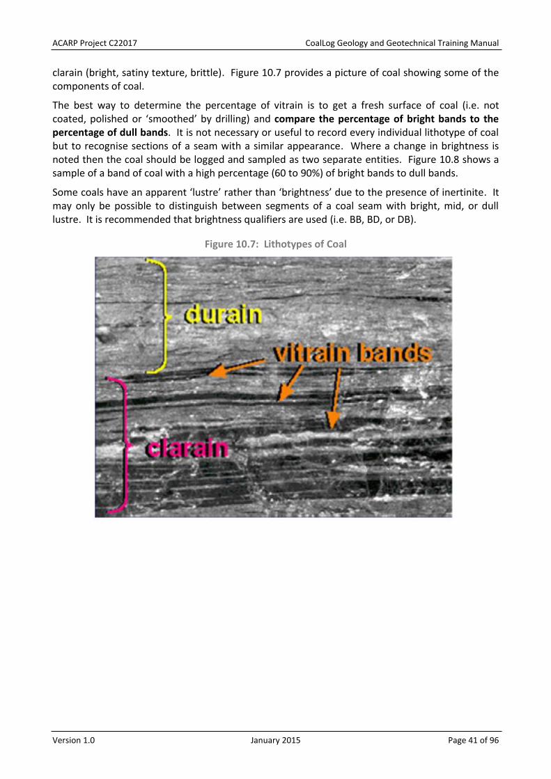
ACARP Project C22017 CoalLog Geology and Geotechnical Training Manual
Version 1.0 January 2015 Page 41 of 96
clarain (bright, satiny texture, brittle). Figure 10.7 provides a picture of coal showing some of the components of coal.
The best way to determine the percentage of vitrain is to get a fresh surface of coal (i.e. not coated, polished or ‘smoothed’ by drilling) and compare the percentage of bright bands to the percentage of dull bands. It is not necessary or useful to record every individual lithotype of coal but to recognise sections of a seam with a similar appearance. Where a change in brightness is noted then the coal should be logged and sampled as two separate entities. Figure 10.8 shows a sample of a band of coal with a high percentage (60 to 90%) of bright bands to dull bands.
Some coals have an apparent ‘lustre’ rather than ‘brightness’ due to the presence of inertinite. It may only be possible to distinguish between segments of a coal seam with bright, mid, or dull lustre. It is recommended that brightness qualifiers are used (i.e. BB, BD, or DB).
Figure 10.7: Lithotypes of Coal

ACARP Project C22017 CoalLog Geology and Geotechnical Training Manual
Version 1.0 January 2015 Page 42 of 96
Figure 10.8: Example of Coal with 60 to 90% Bright Bands
Grain Size 10.7.2.
Any sediment, whether unconsolidated or consolidated into a rock, is classified by its predominant particle or grain size. There are various scales which provide descriptions of the grain size of all sediments. The most familiar scale used historically by geologists is the Wentworth scale. However this is based on an imperial scale and has no direct relationship to the rock material strength and the behaviour of sedimentary material. The scale used by CoalLog is based on adaptation of AS1289 (Methods of testing for geotechnical purposes) which is considered as directly useful by geotechnical engineers as it complies with AS1726 (Geotechnical site investigations) and thereby provides direct linkage to soil behaviour classification systems that rely on particle size ranges, plasticity attributes, and visual-tactile linkages to strength behaviour. This is a logarithmic scale based on multiples of 0.002mm and 0.06mm as shown in Table 10.2 for the most frequently used divisions. A comparison of different scales and grain size definitions is provided in Appendix C.
Table 10.2: Classification of Common Sediment Grain Sizes
Lithology Description
Clay majority of particles are less than 0.002mm
Silt majority of particles are between 0.002 and 0.06mm
Sand majority of particles are between 0.06 and 2mm
Gravel majority of particles are between 2 and 60mm
Further subdivisions of grain sizes and gradational variations are provided in CoalLog as Lithology Qualifier codes. Sand, gravel and sandstone can be divided into ‘fine’, ‘medium’ and ‘coarse’ as shown in Table 10.3. The descriptions of gradational variations are unique and do not imply a

ACARP Project C22017 CoalLog Geology and Geotechnical Training Manual
Version 1.0 January 2015 Page 43 of 96
direction (i.e. ‘fine to medium grained’ has the same meaning as ‘medium to fine grained’). It should be noted that there are no codes in CoalLog for the subdivision of ‘silt’ as this would not be distinguishable in field descriptions.
Table 10.3: Grain Size Subdivisions of Sand, Gravel and Sandstone
Lithology Description
fine grained consists of grains ranging from 0.06 to 0.20mm in size for Sandstone or Sand, and from 2 to 6mm for Gravel
medium grained consists of grains ranging from 0.20 to 0.60mm in size for Sandstone or Sand, and from 6 to 20mm for Gravel
coarse grained consists of grains ranging from 0.60 to 2.00mm in size for Sandstone or Sand, and from 20 to 60mm for Gravel
Unconsolidated sediments can also be subdivided based on the presence of particles of different grain sizes as shown in Table 10.4. These are all available as Lithology Qualifier codes where the description is prominent and the graphic symbol is required. Except for ‘gravelly’, all of these descriptions are available as Lithology Adjective codes where the subdivisions in Table 10.4 are used in the Lithology Qualifier field.
Table 10.4: Grain Size Subdivisions of Unconsolidated Sediments
Lithology Description
clayey having clay sized particles (<0.002mm)
silty having silt sized particles (between 0.002 and 0.06mm)
sandy having sand sized particles (between 0.06 and 2mm)
gravelly having gravel sized particles (between 2 and 60mm)
Similar subdivisions can also be applied to tuffaceous sediments with the addition of ‘mud sized’ which is “having clay and silt sized particles (<0.06mm)”.
Conglomerates have a separate set of Lithology Qualifier codes which are based on the combination of the terms and descriptions provided in Table 10.5.
Table 10.5: Grain Size Subdivisions of Conglomerates
Lithology Description
granular containing grains 2 to 20mm in size
pebbly containing grains 20 to 6 mm in size
cobbly containing grains 60 to 200mm in size
bouldery containing grains >200mm in size
Adjectives 10.7.3.
While coal measure Lithology can be distinguished on the basis of its origin (sedimentary, igneous, or metamorphic), Hues/Colour and Shade, and the use of Lithology Qualifiers for Coal Brightness and Grain Size, it may be necessary to record additional descriptions of key features to differentiate different units. CoalLog provides a large selection of Adjectives which enable description of Quantity, Appearance, Lithological variations, and Inclusions. More significant

ACARP Project C22017 CoalLog Geology and Geotechnical Training Manual
Version 1.0 January 2015 Page 44 of 96
features (i.e. Mineral/Fossil, Sedimentary Feature, Mechanical State, Texture) should be recorded in their own fields.
Any unit which contains a secondary lithology which comprises more than 10% of the unit should be recorded on a separate line with a Lithology Interrelationship and a Lithology %.
It is recommended that these Adjectives are kept to a reasonable number as more than four may not be relevant or worthwhile. Recording of significant features in their relevant field or on separate lines enables them to be searched for and highlighted.
Weathering 10.7.4.
The distinction between weathered or oxidised and fresh rock is a critical parameter to be recorded. In most situations there is a transition from residual soil near the surface to slightly weathered. This change does not occur at a constant gradual rate but can be variable in extent and depth. The boundary between slightly weathered rock and fresh rock is the base of weathering. The base of weathering must be identified in every borehole. This must also be distinguished from the base of Tertiary which may show some similar characteristics.
The degree of Weathering can be assessed visually by the colour change of the Lithology (usually from brown or yellow to grey) as well as the presence of iron staining or mineralisation. No discoloration generally indicates fresh rock. Weathered material may also be less consolidated.
Weathering of coal displays some slightly different characteristics which should be carefully observed and recorded. As coal weathers it loses its brittleness and becomes friable and eventually powdery. This weathering causes a change in key properties of the coal. The point at which the coal loses its key quality(s) is where the base of weathering should be recorded. Table 10.6 provides descriptions of the different stages of weathering which can be observed.

ACARP Project C22017 CoalLog Geology and Geotechnical Training Manual
Version 1.0 January 2015 Page 45 of 96
Table 10.6: Weathering Classification
State Description
Residual soil Soil developed on extremely weathered rock: the mass structure and substance fabric are no longer evident; there is a large change in volume but the soil has not been significantly transported.
Extremely weathered Rock is weathered to such an extent that it has ‘soil’ properties, i.e. it either disintegrates in water or can be remoulded.
Coal has weathered to a powdery or clayey soot, and ranges in colour from black to medium brown with further deterioration.
Distinctly weathered Rock strength and competence has been clearly reduced. The rock may be highly discoloured, usually by iron staining. The rock is usually a deep red or brown colour. Porosity may be increased by leaching, or may be decreased due to deposition of weathering products in pores.
Coal shows some original fabric (cleats/bands etc.) but is friable between the fingers.
Slightly weathered Rock is slightly discoloured but shows little or no change of strength from fresh rock. Usually penetrative weathering along defect surfaces. The rocks are usually an orange or yellow colour.
Coal may show discolouration and may be dusty.
Fresh Rock shows no sign of decomposition or staining.
Sometimes duricrusts will be present within the weathered section. Duricrusts are indurated layers or zones formed by weathering processes involving cementation of the surface soils and weathered rock by calcite (calcrete), silica (silcrete), or iron oxides (ferricrete). Calcrete will appear as hard white or creamy chips while silcrete can range from silica-cemented sand and gravel to an amorphous matrix enriched with small silica particles. Ferricrete is difficult to identify in chips but is often found in association with silcrete.
It is important not to confuse heat affected zones underneath basalt flows or adjacent to igneous intrusions as weathered material. If a surface flow is present, the base of weathering is likely to be at the base of the flow and any discoloured sediments below this horizon should be noted as being heat affected.
In faulted zones and where paleo-horizons exist it may be possible to observe two bases of weathering. These should be noted in Comments and the base of weathering which has greatest impact on the coal resource should be identified.
In accordance with AS 1726 (Geotechnical site investigations), the CoalLog description of Weathering (oxygenated and therefore ground surface-related chemical and physical change processes) is separated from, and not based upon, an assessment of strength.
CoalLog also provides separately for description of Alteration, which may result in superficially similar features to weathering, but is attributable to geochemical and physical changes that are not related to near-surface processes. Based on observations, the classifications for alteration follow the same pattern as for Weathering.

ACARP Project C22017 CoalLog Geology and Geotechnical Training Manual
Version 1.0 January 2015 Page 46 of 96
Estimated Strength 10.7.5.
The strength of any lithological unit can be estimated using basic field tests. This depends initially on whether the unit is ‘Unconsolidated’ or ‘Rock’, and if it is ‘Cohesive’. Field tests include:
squeezing, moulding, or indenting ‘Unconsolidated Cohesive’ material; using finger nail, thumb pressure, or a knife blade on ‘Unconsolidated Cohesionless’; or scratching with a knife or breaking with a hammer on ‘Rock’.
The CoalLog terms and codes are provided in Table 10.7 while detailed descriptions are provided in the CoalLog Dictionary Descriptions.
The estimation of strength using these tests is subjective but the consistent use of them to determine relative strength values provides a useful value.
Table 10.7: Estimated Strength Terms and Codes
Code Term
Unconsolidated Cohesive
C1 Very soft
C2 Soft
C3 Firm
C4 Stiff
C5 Very stiff
C6 Hard
Unconsolidated Cohesionless
S1 Very loose
S2 Loose
S3 Medium dense
S4 Dense
S5 Very dense
Rock
R1 Extremely low strength rock
R2 Very low strength rock
R3 Low strength rock
R4 Medium strength rock
R5 High strength rock
R6 Very high strength rock
R7 Extremely high strength rock
Sedimentary Features in Core 10.7.6.
Following are examples of some Sedimentary Features.
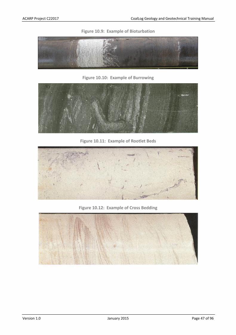
ACARP Project C22017 CoalLog Geology and Geotechnical Training Manual
Version 1.0 January 2015 Page 47 of 96
Figure 10.9: Example of Bioturbation
Figure 10.10: Example of Burrowing
Figure 10.11: Example of Rootlet Beds
Figure 10.12: Example of Cross Bedding

ACARP Project C22017 CoalLog Geology and Geotechnical Training Manual
Version 1.0 January 2015 Page 48 of 96
Figure 10.13: Example of Rip Up Clasts
Figure 10.14: Example of a Sandstone Dyke
Figure 10.15: Example of Slumping
COAL SAMPLING 10.8.
Samples of coal core provide valuable information regarding the quality and other characteristics of coal units and can be used to assist in determining the best mining methods, beneficiation, and marketing for the final product. Therefore every effort should be taken to sample core in a consistent manner so that coal quality variations across the deposit can be modelled.
This procedure also applies to sampling of immediate roof and floor as well as parting samples taken for dilution studies. Sampling for geotechnical studies is described in Section 11.4.
Logging and sampling of cored boreholes should take priority over all other boreholes.
It is recommended that a geophysical log of a pilot or nearby borehole is available to give an indication of the sample intervals to be taken, especially when there are partings (i.e. non-coal intervals) or quality variations throughout a seam.
Generally, sampling occurs at the drill rig as soon as possible after the core is recovered, photographed and logged. However in some situations the core will be boxed and sampled later.

ACARP Project C22017 CoalLog Geology and Geotechnical Training Manual
Version 1.0 January 2015 Page 49 of 96
This is usually to enable the down-hole geophysical log to be recorded, lithological logs to be adjusted, core loss to be reconciled, and/or sample intervals to be selected based on log responses. In this case, the core should be protected from moisture loss and kept in a refrigerated area if not being sampled on the same day.
Do not sample across core loss intervals. Do not sample across core run boundaries.
It is recommended that smaller samples are taken where there is uncertainty about suitable units for analysis as samples can always be combined later.
Sample intervals should reflect consistent lithotypes but may require some force to separate from adjacent lithotypes. If the core doesn’t split easily at a proposed sample boundary, then review the proposed sample intervals and select a weaker bedding plane which is more likely to represent where the lithotypes will naturally separate.
A Sample Number should be recorded on the Lithology Sheet before the sample is taken. The ‘field weight’ of each sample should also be recorded. This could be recorded on the Lithology Sheet or a separate sheet which also records other information about the sample such as ‘date despatched’. It is recommended that the actual sample details (Sample Number, From Depth, To Depth, Thickness, and Lithology) are generated from the database rather than being separately transcribed as this may result in errors.
All bagged samples should be weighed and samples mass recorded prior to transportation to the coal laboratory. A calculation of the expected sample mass can be made using the measured length and an estimated RD. If the variation between the weighed mass and the predicted mass is significant (e.g. >10%) then an error may have been made in recording of sample details (length, diameter, weight) or the estimated RD and all details should be checked.
The calculation of predicted mass uses the following formula:
mass = Pi x radius x radius x length of core x relative density
Preparation for core sampling is critical. Ensure all necessary supplies are available on site. Prepare sample bags where possible. Ensure samples can be readily transported to a secure area at the end of each day.
A chain of custody procedure needs to be established to track samples leaving site and arriving at the testing laboratory. All sample details and analysis instructions should be supplied to the laboratory at the same time as samples are despatched.
Redrill any seam where linear or mass recovery is not representative (as determined by the Competent Person, who is defined by the JORC Code) unless geological conditions are evident that prohibit full recovery. Loss of sample may be due to poor drilling, mishandling of core, or poor recovery (i.e. fines blown away or washed out).
General Procedures 10.8.1.
The following procedures should be followed to ensure the highest possible standard and reliability of sample collection and analysis:
ensure all samples are taken as soon as possible to minimise moisture loss, otherwise store coal in core sock or with plastic cover;
minimise inclusion of excess free moisture; minimise damage to core when separating samples;

ACARP Project C22017 CoalLog Geology and Geotechnical Training Manual
Version 1.0 January 2015 Page 50 of 96
recover all possible core with minimal contamination; and use a brush to ensure all possible fines are retained.
The procedure for placing samples in bags should include:
double bag all samples (in tough {i.e. >60um} plastic bags); include a sample tag with sample number in outer bag; record project name, borehole name, and sample number with a water proof pen on
the outside of each bag – sample depths may also be included; record bag number (as bag x of xx) if multiple bags used for sample interval; seal bag as air tight as possible with tape or cable ties; weigh and record all bagged samples; keep samples in shady or cool area if possible; and transfer all samples to cold storage at end of day if possible.
The procedure for storing and despatching samples should include:
pack sample bags into larger poly sacks (<25kg) or drums (Figure 10.16); seal securely (cable ties, staples, tape or secured lid); label outside with project name, borehole name, sample numbers and bag/drum
number with a water proof pen or paint; keep physical or digital record of all sample bags/drums with contents; transfer all samples to cold storage awaiting despatch if possible; samples should be dispatched to the lab as soon as reasonably possible (recommend at
least once per week); and record date of despatch.
Figure 10.16: Samples Packed in Poly Sacks for Transport

ACARP Project C22017 CoalLog Geology and Geotechnical Training Manual
Version 1.0 January 2015 Page 51 of 96
Specific Procedures 10.8.2.
Every project will have specific requirements regarding sample intervals and size. The rig geologist should ensure familiarity with these requirements and get confirmation before starting sampling. This especially applies to the inclusion or exclusion of partings. The thicknesses highlighted (e.g. 0.3m) in the following dot points are often applied but can be modified to suit project specifications (e.g. many projects where selective mining may be applied will sample coal and partings >0.1m thick). Consistency between boreholes is critical for the data to be useful.
Sample coal:
fresh to slightly weathered mineable coal bands >0.3m thick; where separated from other plies by >0.3m of distinguishable parting; where visibly distinct quality from adjacent coal unit; on appearance where heat affected; according to sample intervals marked on detailed (1:20) geophysical or graphic log from
pilot borehole (as a minimum); according to correlated seams/plies; in more detail than specified if any uncertainty exists (as samples can be combined later
but cannot be subdivided); separately from any carbonaceous layer at roof or floor contact unless <0.02m and not
visually distinct or easily split; or separately where a stone band of greater thickness separates the coal band from the
designated seam roof or floor.
Sample partings:
where >0.3m thick; where distinguishable from coal by lithology, colour, hardness, or coal quality; or which contain significant coal bands or coal fragments or carbonaceous material.
In general, where a parting is not sampled separately it should be included with the coal unit below for an open-cut deposit, and with the coal unit above for an underground deposit.
Retain 0.25m of roof and floor material from top and base of seams and where interburden is >0.3m and <0.5m in core boxes.
Note: it is always good practice to oversample if you are unsure about sample or ply boundaries. Samples can always be combined at a later date in the laboratory.
Boxing Core 10.8.3.
If core is to be stored for later sampling or review it should be placed in appropriate core boxes or trays. It is assumed that core has been marked according to procedures in Section 10.5.
All core boxes should be labelled on the front and one end from left-to-right so they can be read in racks, with the following:
project name; borehole number; box number; and from and to depths (of the core in the box).
Suitable markers (e.g. wood or polystyrene block) should be placed inside the box as follows:

ACARP Project C22017 CoalLog Geology and Geotechnical Training Manual
Version 1.0 January 2015 Page 52 of 96
at the top left with the borehole number, box number, and core start depth; at the end of each run with letters ‘EOR’ (end of run), run number, and depth; at the start of a new run where not continuous from previous run with letters ‘SOR’
(start of run), run number, and depth; where a sample has been taken with sample number and to and from depths (marker
does not need to match size of sample); where core loss has been recorded; and at the bottom right with the end of core (EOC) or total depth (TD)of the borehole.
Position the core in a box in a way that minimises manual handling and core damage. It is recommended that additional blocks are placed into gaps in the core trays to stop the core moving during transport. Broken or fragmented core may be rolled into an appropriate length of PVC split tubing to ensure integrity in transferal to the core box, and during transport and storage.
Figure 10.17 shows an example of the correct layout of core in a core box. This shows that details such as project name (removed from this image), borehole name (removed from this image), box number and depths can also be written on the edges of the box. Note that breaks have occurred in the core during boxing or transportation as they are not marked.
Figure 10.17: Example of Boxed Core
Transporting Core 10.8.4.
While on site core boxes should be located so they are easily accessed and securely stored where they will not be affected by weather or other disturbance. Position the box in a manner that prevents any chance of the core box falling or the core being uncovered.
Core boxes should be secured and transported to a core shed and stored appropriately as soon as possible. Strap core boxes into a vehicle to avoid movement and reduce the safety hazard during transit.
GAS OBSERVATIONS 10.9.
The presence or absence of gas in the core is an important observation to make.
Gas is usually most obvious in the coal seam (for coal drilling in Australia) but can be seen occasionally in other lithologies.

ACARP Project C22017 CoalLog Geology and Geotechnical Training Manual
Version 1.0 January 2015 Page 53 of 96
The gas in coal measures is generally made up of varying proportions of methane (CH4), carbon dioxide (CO2), and hydrogen sulphide (H2S). Depending on the total amount of gas and the proportion of each type, the presence of gas can have impacts on various aspects of the mining process, such as:
Underground safety – breathability of air; Underground safety – risk of explosion or outbursts; Potential for gas production from seam; or Fugitive emissions from the mine (greenhouse gas remediation).
Note: All drilling programs should require a gas monitor be placed on the rig and operated by someone trained and authorised in its use (usually the driller). All safety instructions issued by this person must be followed. If gas levels outside the borehole reach certain levels, drilling may be suspended, the area evacuated, and/or measures taken to reduce the production of gas from the borehole.
Gas is present in a number of forms in the rock (adsorbed onto surfaces, in joints, dissolved in fluids), and the desorbable gas content can be measured in the field or the laboratory. Suitable equipment is required to undertake these measurements. The gas composition can also be determined if a sample is taken according to standard procedures.
On boreholes where these tests are not being carried out, it is imperative that a good record is kept of non-quantitative gas field observations. The CoalLog standard for field observations for gas in the core is shown in Table 10.8.
Table 10.8: Gas Codes and Descriptions
Code Value Description
T Trace No visible bubbling of wet core, but slight smell of gas if H2S is present and/or slight sounds of crackling from core when listened to closely.
L Low Bubbles can be seen slowly forming when core is wet with high viscosity fluid (saliva or drilling mud). May not be visible when wet with water. Slight or moderate smell if H2S is present.
M Moderate Core shows bubbles forming on any wet surface, and sounds can be easily heard from inside the core.
H High Core bubbles readily and forms foam when wet with high viscosity fluid (saliva or drilling mud).
V Very High Core fizzes, pieces of coal may fracture from the surface, very loud fizzing and crackling noises when heard from close to core. Core may expand, fracture or crack when removed from splits.
N No H2S No hydrogen sulphide detected.
P H2S Hydrogen sulphide detected.
This scale can also be adapted for presence of gas in drill cuttings (chips), for example, a slight smell, sounds of fizzing, or presence/formation of foam in the chip pile.

ACARP Project C22017 CoalLog Geology and Geotechnical Training Manual
Version 1.0 January 2015 Page 54 of 96
GEOTECHNICAL LOGGING 11.
The purpose of these notes is to help provide an accurate and comprehensive record of the geotechnical conditions. Appropriate sources for guidance and terminology include:
CoalLog Manual (Larkin & Green, 2012); Australian Standard Site Investigation Code AS 1726 (1993); Rock Characterization Testing and Monitoring – ISRM Suggested Methods (1981); and Logging of Rock Cores for Engineering Purposes by the Geological Society (1970).
The following guidelines for recording geotechnical data from cored boreholes are generally based on fields, codes and descriptions provided in CoalLog. CoalLog provides recommended logging sheets which give the option to record limited geotechnical data on the Lithology Sheet or more comprehensive details of RMUs and defects in the RMU & Defect Sheet.
DEFECT LOGGING OF CORE 11.1.
Observing and recording defect information is a critical task because the frequency, geometry and mechanical properties of the defects will affect the overall behaviour of the rock mass.
Defects in a rock mass occur at a variety of scales. When logging core, consider core scale defects only and be concerned with direct observation, not interpretation. For example, it is important to record the characteristics of individual faults in the core. Later, when a geological model is created, it may be recognised that collectively, a zone of faults observed in core, may actually be the individual shear surfaces of a single, larger scale structure. Consequently when logging rock cores, the following should be considered:
Drilling usually causes some disturbance of defect surfaces or filling. There is only a limited extent of any defect surface exposed in a core interval (e.g. is it
cross-bedded sandstone or horizontal beds disturbed by nearby faulting?). Core drilling gives no information at all on the extent of a defect surface, whether its
orientation changes with distance, and what happens when defects intersect outside of the core (e.g. is the feature a shear associated with limited movement or a fault signifying a substantial displacement?).
It is best practice to mark defects within the core with a red paint pen marker, so as to distinguish between natural defects recorded at the time of logging, and handling-induced defects post-drilling. For simple defects such as a sub-horizontal bedding plane parting or joint, mark the defect with an “X” that crosses both sides of the defect plane. For more complex defects, such as sub-vertical, undulating joints, it is recommended to mark the defect with “X”s along its extent within the core.
Record defect depths at their mid-point. Defects encompassing a zone should also be logged at their mid-point depth. Regardless of whether the defect is logged at the top, mid-point, or base depth, it is important to maintain consistency within each borehole and across the project for eventual correlation.

ACARP Project C22017 CoalLog Geology and Geotechnical Training Manual
Version 1.0 January 2015 Page 55 of 96
Defect Type 11.1.1.
Within a rock mass there will be a variety of discontinuities which may or may not constitute a defect in the sense of having inferior mechanical properties compared with the rock substance. For example a joint (zero tensile strength) is clearly much weaker than a quartz vein that is thermally and chemically bonded to the host rock.
The geotechnical log should record all the discontinuities that occur in a rock mass so that their impact on the behaviour of the rock mass can be evaluated and appropriate shear strength parameters can be assigned to it.
Defects or discontinuities should be identified as ‘natural’ or ‘induced’. It is important to distinguish between a natural joint and a drilling or handling induced defect. It is not always obvious whether a defect is natural or induced’ but no one is better placed to make that evaluation than the person logging the core as it comes out of the ground. An obvious sign of drilling-induced breaks are ‘catch marks’ at or near the defect, as well as discing or spinning marks on the defect surface. Table 11.1 lists the natural Defect Type that is encountered in coal measures rocks and their characteristics. Table 11.2 lists and describes induced Defect Type.
Table 11.1: Description of Natural Defect Types
Code Defect Description
BP Bedding plane parting
Bedding plane parting is the separation between bedding units (see Figure 11.1).
BZ Broken Zone A generic term for broken rock (see Figure 11.2). It may be possible to more precisely characterise a BZ as a fault breccia or shear zone.
CE Coal cleat
Cleat is a small-scale fracture within coal, often with infilling, that has very limited surface extent. When discrete fracture surfaces in coal are larger than about 30mm they should be described as joints rather than cleats.
CL Clay band Band or seam of any type of clay that may be the product of rock substance weathering or alteration.
CF
Contraction fracture
Generally curviplanar features developed in volcanic lavas or in country rock adjacent to intrusive dykes and sills.
XB
Cross bedding
A sedimentary feature in which layers dip at various angles to the dip of the formation.
DY Dyke An approximately vertical intrusion, usually igneous in origin but rarely may be sedimentary in origin.
FT Fault
A fault is plane of shear failure along which movement has occurred (see Figure 11.3). Often it will be characterised by slickensided or polished surfaces in which mineral grains are aligned to the direction of shearing. While the term “fault” is usually applied to larger scale structures, within the context of core logging it should be applied to any surface along which movement has occurred. Thus the commonly used terms ‘fault’ and ‘shear’ (as in single shear) may be conflated for the purpose of core logging.

ACARP Project C22017 CoalLog Geology and Geotechnical Training Manual
Version 1.0 January 2015 Page 56 of 96
Code Defect Description
FO Foliation An alignment of minerals in response to tectonic stresses usually associated with metamorphic rocks but may be observed in sedimentary rocks (e.g. as an axial plane foliation within folded strata).
JN Joint A discontinuity along which no relative movement is obvious. Usually developed from tectonic or thermal contraction processes (see Figure 11.4).
SH Shear zone Any zone that exhibits multiple shear surfaces. For example, if the broken surfaces in Figure 11.2 show signs of shearing the whole zone would be logged as SH rather than BZ.
SI Sill An approximately horizontal intrusion, usually igneous in origin but very rarely may be sedimentary in origin.
SO Softened zone (non-tectonic)
Zone with any shape having reduced rock substance strength and possibly also discolouration. This zone should be covered by a litho description and strength classification and logged as a low strength RMU.
VN Vein
Infilled discontinuities formed by separation and infilling of defects, usually consisting of one main mineral, mostly calcite or quartz. Generally has irregular shape and variable thickness. Pressure solution effects may produce veins that are difficult to interpret.
Figure 11.1: Example of a Bedding Plane Parting at a Sandstone/Siltstone Contact
Figure 11.2: Example of a Broken Zone in a Claystone Unit
Note: If careful observation determines that the surfaces show signs of shearing then it could be logged as a Shear Zone (SH) which has been partially destroyed by the coring process.
Figure 11.3: Example of a Fault in an Interbedded Sandstone/Siltstone Unit
Note: As there is evidence of movement along this shear it is logged as a Fault (FT).

ACARP Project C22017 CoalLog Geology and Geotechnical Training Manual
Version 1.0 January 2015 Page 57 of 96
Figure 11.4: Example of a Joint in an Interbedded Sandstone/Siltstone Unit, Dipping at 75°
Table 11.2: Induced and Non-Intact Defect Types
Code Defect Description
DS Discing Generally a result of poor drilling equipment or practice in closely bedded or laminated rock types producing discs of core broken along bedding or other structure normal to the core axis. May also be the result of stress relief.
DB Drilling-induced break
A core break identified as being caused by drilling, extrusion from the inner tube or handling; core breaks are not always easily distinguishable from natural defects but mostly have irregular shape and rough surface.
DZ Drilling-induced broken zone
Section of core fragmented by drilling and/or handling into pieces mostly less than core diameter size up to twice core diameter size.
Figure 11.5: Example of Discing in Interlaminated Sandstone/Siltstone
Number of Defects and Defect Spacing 11.1.2.
Measure the mean and range spacing for each set of defects where possible. Table 11.3 gives definitions of terminology that may be used in describing Defect Spacing in the Lithology Sheet.
Table 11.3: Defect Spacing Classification (Lithology Sheet)
Code Defect Spacing (mm)
EW Extremely wide >2,000
VW Very wide 600-2,000
WI Wide 200-600
MW Moderately wide 60-200
MN Moderately narrow 20-60
NA Narrow 6-20
VN Very narrow 6
The number of defects and the actual defect spacing should be measured and recorded in the RMU & Defect Sheet.

ACARP Project C22017 CoalLog Geology and Geotechnical Training Manual
Version 1.0 January 2015 Page 58 of 96
The number of natural discontinuities over an interval (RMU) is recorded in the column labelled Number of Defects. If there are more than 20 fractures over a 0.5m interval, record 99 in this column.
Defect Spacing is a record in millimetres of the average interval between each defect within a RMU. If that spacing is >600mm then record 999 in the Defect Spacing column. This equates to the Australian Standard definition of ‘very wide’.
Rock Quality Designation (RQD) and Fracture Frequency, described in Sections 11.3.1 and 11.3.2, provide an overall measure of defect spacing.
Defect Intact 11.1.3.
If the defect or defects in the core are intact then an ‘I’ must be entered in the Defect Intact column of the geotechnical log. This can be applied to bedding planes or veins for example, but should not be used to distinguish natural defects from induced features. If the defect or defects are not intact then the Defect Intact column must be left blank.
Defect Continuity 11.1.4.
Defect Continuity describes the termination nature of a defect or defects (e.g. whether a defect extends through the core diameter or terminates against another defect). This is described in more detail in Table 11.4 and shown in Figure 11.6.
Table 11.4: Defect Continuity Classification
Code Defect Description
C Continuous across core width Extends through core diameter
D Discontinuous across core width Does not extend through core diameter
V Divaricates Defect splits in two
T Truncated within core width Terminates against another structure

ACARP Project C22017 CoalLog Geology and Geotechnical Training Manual
Version 1.0 January 2015 Page 59 of 96
Figure 11.6: Defect Continuity Classification
Defect Orientation 11.1.5.
The Defect Orientation of all structures should be recorded if the core is oriented or the feature has been defined by an oriented tool (e.g. acoustic or optical scanner). Ensure that the convention adopted is clearly noted, i.e. is the measurement of a dip value or an angle with respect to the core axis? Record whether the azimuth values are magnetic or grid.
Defect Dip Orientation Method 11.1.6.
The general convention in the Australian coal industry is that all dip angles should be recorded relative to the perpendicular to the core axis. In other words, if the borehole is vertical, then the dip of any feature is measured from the horizontal. The Defect Dip Orientation Method column should be filled with one of the methods shown in Table 11.5.
Table 11.5: Defect Dip Orientation Method
Code Dip Orientation Method
D Directly measured from reference line
E Estimated
I Indirectly measured
A Measured from televiewer

ACARP Project C22017 CoalLog Geology and Geotechnical Training Manual
Version 1.0 January 2015 Page 60 of 96
Figure 11.7: Recommended Protractor (Starrett) for Accurately Measured Defect and Bedding Angles
Defect Surface Shape 11.1.7.
The Defect Surface Shape refers to the shape of the defect surface across the core. The classification scheme is shown in Table 11.6.
Table 11.6: Defect Surface Shape Classification
Code Surface Shape Description
C Concave/convex One trough or crest across core width
I Irregular Many sharp troughs and crests in all directions across core width
P Planar Surface with no obvious curves or irregularities across core width
S Stepped Distinct steps in any direction across core width
U Undulose Rounded crests and troughs in one or more directions across core width
Defect Surface Roughness 11.1.8.
The Defect Surface Roughness is the inherent roughness and shape relative to the mean plane of a logged defect. A descriptor of Surface Roughness is based on the ISRM (1981) method. Originally, this scheme was used to describe intermediate scale (several metres) roughness (stepped, undulating and planar) and small scale (several centimetres) roughness (rough, smooth and slickensided). Nowadays, the terminology of this method is also used in describing core scale defects. The classification scheme is shown in Table 11.7 and shown in combination with Surface Shape in Figure 11.8.
Table 11.7: Defect Surface Roughness Classification
Code Surface Shape Description
K Slickensided Striations visible on defect surface that may or may not be polished (the angle of the striations to the dip direction of the defect should be noted)
P Polished Smooth but without striations (reflects light)
R Rough Rough to touch (sandpaper feel)
S Smooth Smooth to feel but not polished or slickensided

ACARP Project C22017 CoalLog Geology and Geotechnical Training Manual
Version 1.0 January 2015 Page 61 of 96
Figure 11.8: Typical Surface Roughness and Shape Profiles
(ISRM (1981) Suggested Nomenclature) (The length of each profile is in the range 1 to 10m. H:V scales are the same.)
Defect Infill Type 11.1.9.
There are numerous Defect Infill Types provided in the CoalLog Dictionary. Mostly the Infill Type is a mineral but it may also be a rock type (e.g. a clay gouge). There can be a Primary Type and a Secondary Type.

ACARP Project C22017 CoalLog Geology and Geotechnical Training Manual
Version 1.0 January 2015 Page 62 of 96
Defect Infill Mode 11.1.10.
The Defect Infill Mode describes the physical mode of emplacement of the infill (e.g. blebs, gouge, coating). Note that the infill can occur as a stain, a trace, or a coating. The differences between these types are provided in Table 11.8. See the CoalLog Dictionary for a full list of Infill Modes.
Table 11.8: Description of Defect Surface Infill Modes
Term Definition
stain No visible coating or infilling but surfaces are discoloured by mineral staining
trace A visible coating or infilling of soil or mineral substance but usually unable to be measured (less than 1mm)
coating A visible coating or infilling of a mineral substance, greater than 1 mm thick.
ESTIMATED STRENGTH LOGGING OF CORE 11.2.
Soil Strength 11.2.1.
The way soil strength is evaluated depends on whether the soil is:
Cohesive (clayey); or Cohesionless (sandy).
When a soil material is a mix of cohesionless and cohesive components (e.g. sandy clay) its engineering behaviour is cohesive (clayey) when the clay component exceeds about 20%.
Table 11.9 shows the classification scheme for the Estimated Strength of cohesive (clayey) soils, which requires the use of a pocket penetrometer (pp), an example of which is shown in Figure 11.9.
Table 11.9: Cohesive Soil Strength Classification
Code Strength Classification
Su* (kPa)
Strength Assessment
C1 Very soft <12 Extrudes between finders when squeezed in
hand (use PP)
C2 Soft 12-25 Can be moulded by light finger pressure (use PP)
C3 Firm 25-50 Can be moulded by strong finger pressure
(use PP)
C4 Stiff 50-100 Cannot be moulded by fingers
Can be indented with thumb (use PP)
C5 Very stiff 100-200 Can be indented only by thumbnail
PP use becomes marginal
C6 Hard >200
Can only be indented with difficulty by thumb-nail
Peels readily with knife (use UCS)
* Su = undrained shear strength

ACARP Project C22017 CoalLog Geology and Geotechnical Training Manual
Version 1.0 January 2015 Page 63 of 96
Figure 11.9: Example of a Pocket Soil Penetrometer (Humboldt) for Assessing Cohesive Soil Strength
The geotechnical strength of cohesionless (sandy) soils is directly related to relative density and mineralogy. Relative density may be roughly inferred from drilling and can be indirectly measured using the Standard Penetration Test (SPT). It is often not practical to carry out such testing during coal exploration drilling, however the strength of cohesionless soils based on relative density can be inferred from the guidelines in Table 11.10.
Table 11.10: Cohesionless Soil Strength Classification
Code Strength Classification
Relative Density Strength Assessment
S1 Very loose ≤15 Awkward to walk; feet slip
SPT 0-4
S2 Loose >15 ≤35 Uncomfortable to walk quickly (feet slip)
SPT 4-10
S3 Medium dense >35 ≤65 Comfortable walking (footprint <15 mm deep)
SPT 10-30
S4 Dense >65 ≤85 Firm walking (footprint <5 mm deep)
SPT 30-50
S5 Very dense >85 Hard surface (footprint indentation minimal)
SPT >50
Rock Strength 11.2.2.
The most meaningful index of rock strength is Uniaxial Compressive Strength (UCS). This is determined in a laboratory. Great care must be taken to ensure that samples remain at field moisture content before being tested. Samples should be taken within five minutes of core being recovered, enclosed with moisture proof wrapping, and stored carefully before being tested in a timely manner (see Section 11.4). If this level of care is not taken, then the samples will dry out and give test results that indicate strengths much higher than the true in situ conditions.
An alternative testing technique measures Point Load Strength (see Section 11.5.1). This test is often performed at the drill site as the core is being recovered, but can also be determined in a laboratory. The Point Load Strength Index (Is50) is correlated to UCS, but the correlation varies with the actual rock strength and the rock type. Field test results can be recorded in the Point Load Data Sheet.

ACARP Project C22017 CoalLog Geology and Geotechnical Training Manual
Version 1.0 January 2015 Page 64 of 96
Field-based tactile-visual assessments can be made and with practice and feedback from laboratory tests can provide fit for purpose assessment of rock strength using the criteria shown in the right hand column of Table 11.11. A steel knife or blade (depending on site restrictions) should be used, as shown in Figure 11.10.
Figure 11.10: Example of Tactile Rock Strength Assessment of Extremely Low Strength Sandstone in HQ3 Core
Table 11.11: Rock Strength Classification
Code Strength Classification
Relative Density
Strength Assessment
R1 Extremely Low <1 May be broken by hand and remoulded (with the
addition of water if necessary) to a material with soil properties
R2 Very Low 1-5 Crumbles under a single firm hammer blow
Can be peeled with a knife
R3 Low 5-10
Breaks under a single firm hammer blow
Scored with a knife (but not peeled)
Core 50mm diameter x 150mm long breaks by hand
R4 Medium 10-25
Breaks under 1 to 3 hammer blows
Can be scratched (but not scored) with a knife
Core 50mm diameter x 300 mm long is very hard to break by hand
R5 High 25-50
Breaks under 3 to 5 hammer blows
Hard to scratch with a knife but steel leaves mark on core
Can be scratched with tungsten tipped scratch tool
Hard sound when hit with a hammer
Intact core cannot be broken by hand
R6 Very High 50-100
Breaks under 1 hammer blow if resting on solid surface
Cannot be scratched by a knife
Can be scratched with difficulty by tungsten tipped scratch tool
Dull ringing sound when hit with hammer
R7 Extremely High >100
Difficult to break with a hammer even if resting on a solid surface
Bright ringing sound when hit by hammer
Note: always use appropriate PPE, notably eye and hand protection.

ACARP Project C22017 CoalLog Geology and Geotechnical Training Manual
Version 1.0 January 2015 Page 65 of 96
ROCK MASS UNIT LOGGING 11.3.
A RMU is not a lithological unit but a unit greater than 200mm in length with common geotechnical characteristics, such as lithology, weathering, strength, RQD, or defect spacing. It may consist of a group of adjacent lithological units which all have the same geotechnical characteristics (e.g. ‘sandstone interbedded with siltstone’ and ‘siltstone interbedded with sandstone’ may be merged into a single RMU). If part of a single lithological unit has different geotechnical characteristics to the rest of the unit, then it should be divided into a separate lithological unit for each RMU, even though the lithology hasn’t changed. For example, ‘massive sandstone’ split into ‘fresh’ and ‘slightly weathered’ RMUs as shown in Figure 11.11.
Figure 11.11: An Example of RMU Classification
Rock Quality Designation 11.3.1.
RQD was introduced by Deere et al. (1967) as a way of correlating natural fracturing intensity with engineering performance of a rock mass.

ACARP Project C22017 CoalLog Geology and Geotechnical Training Manual
Version 1.0 January 2015 Page 66 of 96
RQD measurements have been based on the core run in coal projects and calculated using the following equation:
LengthRun
long 100mmsticks core oflength RQD
%
The original RQD measurement was intended to apply to one or more core runs within a single lithological unit. However, the ISRM (1981) suggest “… that RQD values are determined for variable rather than fixed lengths of core run. To be meaningful for engineering interpretation, values of RQD for individual beds, structural domains, weakness zones etc. should therefore be logged separately, so as to indicate any inherent variability, and provide a more accurate picture of the location and width of zones with low or zero RQD values.” Therefore, the ‘Run Length’ in the above equation should be replaced by a ‘Cored Length’ based on a lithological or geotechnical parameter.
In accordance with ISRM (1981) p47, the length of individual core pieces should be assessed along the centre line of the core, so that discontinuities that happen to be parallel with the borehole will not unduly penalise the RQD values of an otherwise massive rock.
An example of the calculation of RQD is shown in Figure 11.12.
Figure 11.12: Example of How to Calculate RQD
Therefore RQD is defined as the sum of solid core pieces greater than 100mm in length over a cored interval expressed as a percentage of the interval length. All natural discontinuities, both bedding parting and joint planes, are included in the computation. Measurements are made axially, that is along the centre-line of the core. The easiest way to measure is accumulatively with the tape, that is, pinch the tape between finger and thumb at the base of the first measured

ACARP Project C22017 CoalLog Geology and Geotechnical Training Manual
Version 1.0 January 2015 Page 67 of 96
length, then advance this point to the top of the second measured length and repeat to the end of the core interval.
Sound core with a single fracture parallel to the core axis would be counted as intact rock and assigned an RQD of 100% (or just less than) depending on whether the joint is open or tight. RQD is essential in the computation of the Coal Mine Roof Rating (CMRR) but may be calculated from fracture frequency as long as geomechanical unit locations are properly recorded.
Boreholes in the coal industry are predominantly drilled vertically. Consequently, steeply dipping or vertical defects will be grossly under-represented in the recovered core. This may result in an over-estimation of the overall quality of the rock mass.
Fracture Frequency 11.3.2.
An alternative and complementary measure of rock quality is fracture frequency. Fractures are normally expressed as a fracture frequency index, which is defined as the total number of fractures present in a unit of length of core (for a particular rock mass unit). This unit length is usually 1m. All natural breaks are counted, including both bedding partings and joints. Natural fracture frequency is important for the computation of CMRR.
A classification of the fracture frequency is shown in Table 11.12. This is not recorded in CoalLog as it is an index determined from recording of the Number of Defects and the Defect Spacing as discussed in Section 11.1.2.
Table 11.12: Fracture Classification Based on Fracture Frequency in Core
Core Description Fracture Spacing Fracture Frequency/m
Unbroken >2,000 <0.5
Slightly fractured 600-2,000 1.7-0.5
Moderately fractured 200-600 5-1.7
Fractured 60-200 17-5
Highly fractured 20-60 50-17
Extremely fractured 6-20 170-50
Fragmented <6 >150
GEOTECHNICAL SAMPLING 11.4.
Immediate coal seam roof and floor rocks need to be sampled in order to establish their rock strength properties and their propensity to disintegrate. There are implications for both open-cut and underground mining situations.
For example:
The nature and strength of the roof rocks is integral in the design and safety of underground mining, including understanding how the roof will cave in a longwall situation.
A soft floor in an open-cut mine can impact on the traffickability for the heavy trucks, loaders and excavators which have to operate on that floor.

ACARP Project C22017 CoalLog Geology and Geotechnical Training Manual
Version 1.0 January 2015 Page 68 of 96
A weak layer in the immediate floor rocks below a coal seam can result in shearing movements and ‘floor heave’ caused by low-wall loading, sometimes with catastrophic effects.
Accordingly, individual roof and floor samples may need to undergo two distinct testing regimes being for geotechnical purposes, and for ‘coal quality’ to assess their potential dilution effects.
This may mean that individual samples must first be sent to a geotechnical testing laboratory where they might undergo destructive procedures such as UCS testing and then be sent to a coal quality laboratory.
In addition to the strength of the coal itself, the rock mass properties of a coal seam roof are especially important in an underground mine scenario. The zone that will form the roof to the mine (during development and/or extraction) should be thoroughly tested, to provide the necessary information to enable the design of mine openings and roof support strategies.
A good geological understanding of the roof and its geotechnical implications needs to be developed since, for example, during mining, 2.4m-long roof bolts might not be very useful or effective if there is a persistent, thin, weak, tuffaceous claystone layer in the roof 2.4m above the coal seam.
Underground longwall engineers also need to understand how the roof rocks will react and cave as the longwall advances. While a strong, thickly-bedded sandstone roof would be beneficial from a dilution and bord and pillar roof perspective, its strength and propensity not to fail would have serious negative implications for a longwall operation which requires the roof strata to collapse progressively behind the shearer.
When the roof fails behind an advancing longwall panel, the extent to which the caved zone extends upwards from the void space left from the extraction of the coal is dependent on a number of variables including the mining depth, inherent stresses in the rock mass, and the thickness of the coal seam mined.
A thin seam mined at shallow depth will have a narrower caving zone than will a thick seam mined at greater depth.
In addition to detailed geotechnical logging of the core above a coal seam, it is important for the geologist to understand how the rock mass will likely respond during mining and to collect samples accordingly. This includes both sample quantity (relative location, number, and size) and quality (suitability) to enable all the required testing regimes to be completed.
It is important that geotechnical samples are received and able to be tested at the laboratory in a condition that matches their ‘in situ’ condition, or as close as possible to ‘as sampled’. A piece of core left in the sun at the drill site for half an hour before it is sampled will dry out and have a wholly different response in the laboratory compared with saturated rock ‘in situ’.
Consequently, geotechnical sampling needs to be done at the drill site, within five minutes after the core has been exposed. Geotechnical samples should be received at the laboratory as quickly as possible and in a physical and mechanical condition that best approximates their condition the instant the core barrel was opened. This particularly applies to preserving the moisture content of the core.
Ensure geotechnical samples are securely wrapped and packaged to prevent breakage during transport to the lab (which may be hundreds of kilometres away) and are not thrown into the back of a support vehicle and driven around onsite for days.

ACARP Project C22017 CoalLog Geology and Geotechnical Training Manual
Version 1.0 January 2015 Page 69 of 96
Every sample is precious, and all samples should be treated as both valuable and irreplaceable.
Core Samples 11.4.1.
Rock core samples are generally taken for two reasons:
To determine the material properties of the intact rock and thus to establish a correlation with the geophysical logs e.g. relating sonic velocity to UCS; and
To determine the shear strength of defects within the rock.
In both cases, samples need to be taken as soon as the core has been extruded from the splits, and certainly within five minutes, otherwise irreversible drying out will occur. Drying affects the strength of the core. Tested strengths may be up to two or three times greater than the in situ strengths, just because of the drying out.
If it is not possible to take and wrap the samples for testing within two minutes of the core being extruded from the splits:
identify the samples within the core; and cover the core with a wet cloth until ready to take the sample.
To preserve sample moisture content and structural integrity:
Identify the ‘up’ direction of the sample for reference in later marking. Add a little free moisture to the sample before sealing it. Wrap the sample in cling film; the cling film will be in close contact with the sample and
will help to reinforce it but it can breathe. Wet the outer surface of the cling film and then wrap with another layer of cling film, as
this will retard the rate of drying-back. Wrap the wrapped sample in catering grade aluminium foil; this stiffens the sample and
provides further sealing against moisture loss. Wrap heavy duty duct tape around the sample; this provides additional sealing and
protection, and provides a good surface on which to write the sample details using a permanent marking pen;
Mark the wrapped sample with details including the ‘up’ direction. If the sample is delicate or will be transported for a long distance, reinforce the
wrapped sample with appropriately sized split PVC pipe, using rags for additional padding to fill any gaps between the wrapped sample and the split PVC pipe. Duct tape the whole assembly, including the ends, so that the sample cannot slide out.

ACARP Project C22017 CoalLog Geology and Geotechnical Training Manual
Version 1.0 January 2015 Page 70 of 96
Figure 11.13: Wrapping a Geotechnical Sample
Figure 11.14: Labelled Geotechnical Sample
Non-core Samples 11.4.2.
Samples may be taken for a variety of geotechnical tests. Preservation of moisture content may not be as critical as for samples taken for strength testing.
Table 11.13 below indicates the size of samples required for common geotechnical tests.

ACARP Project C22017 CoalLog Geology and Geotechnical Training Manual
Version 1.0 January 2015 Page 71 of 96
Table 11.13: Sample Size Requirements for Common Geotechnical Tests
Geotechnical Test Minimum Sample Requirement
Atterberg Limits Fine-grained soils: 1kg Medium-grained soils: 5kg Coarse-grained soils: 10kg
Grading Clay: 500g Sands (up to 2mm): 1kg Gravels: 30kg
Slaking and Dispersion Potentials 100mm core, or 5 to 50g (size of two thumbs)
Triaxial Strength (soils) Minimum length 2.2 times greater than core diameter
UCS Minimum length 2.7 to 3 times greater than core diameter
Direct Shear (rock core) Specimen length >50mm
Hoek Triaxial (Rock) Minimum length 2 times greater than core diameter
Slake Durability 10 pieces, each 40 to 60g (size of two thumbs)
Point Load Strength Length greater than core diameter
Indirect Tensile Strength (ITS) Length greater than core diameter
Tips and Tricks 11.4.3.
Aluminium foil is very useful for holding together samples that include geological defects.
In the field, protect samples by storing them in a shady location; take them back to a storage facility each night.
Samples should not be kept for extended periods in an air-conditioned environment, as the air has a low humidity and will dry out the samples.
Transport the samples to the laboratory for testing as quickly as possible. Core trays provide ideal protection (Figure 11.15). Pack the samples carefully and fill the empty spaces (not shown in Figure 11.15) so that they cannot move about and become damaged.
Figure 11.15: Geotechnical Samples in a Core Box

ACARP Project C22017 CoalLog Geology and Geotechnical Training Manual
Version 1.0 January 2015 Page 72 of 96
GEOTECHNICAL TESTING 11.5.
Point Load Strength Test 11.5.1.
Field testing of drill core may include determination of the point load strength index as a quick means of inferring the UCS of coal measures rocks. Figure 11.16 shows a point load testing machine. The particular model shown uses strain gauges to measure the load being transmitted to the platens. Other models use pressure gauges to measure the hydraulic pressure in the hydraulic jack that is used to apply the load to the platens.
Figure 11.16: A Point Load Testing Machine
Care should be taken to ensure that whatever method of measuring the load is used it is calibrated. A detailed test procedure is described in “Suggested Method for Determining Point Load Strength ISRM 1985” (https://www.isrm.net).
Point load test can be carried out on core samples as well as irregular lumps as shown in Figure 11.17. Samples should be at in situ moisture content.
Invalid tests occur quite often and data from these should be excluded from any data sets that are developed. Examples of valid and invalid tests are shown in Figure 11.17.

ACARP Project C22017 CoalLog Geology and Geotechnical Training Manual
Version 1.0 January 2015 Page 73 of 96
Figure 11.17: Typical Modes of Failure for Valid and Invalid Tests (ISRM, 1985)
Information to be included as part of all point load strength index tests is:
dimensions of the core sample tested (core width and length); whether the test was carried out perpendicular or parallel to bedding; and the nature of the failure and whether it occurred through intact rock or pre-maturely
along a healed joint or vein.
For geotechnical investigations it is better to have some, albeit sparse, point load strength data to use rather than having none at all. Therefore, while a complete set of point load strength tests performed every metre or every run is preferable, it is recommended that at least an occasional sample is taken throughout the stratigraphic sequence.
Godfrey Slaking Test 11.5.2.
The standard test for slaking is the Emerson Class Number test which is described in AS1289-2000. For field purposes the Godfrey Slaking Grade test is easier to perform. The test was developed by Nigel Godfrey as part of his Master’s degree research based in the Bowen Basin during the 1980s. The test has proven to be so useful that it is used widely, although it has not been formally published.
The Godfrey Slaking Grade is evaluated by adding small lumps (5 to 20mm) to a container of distilled or potable water and observing the reaction over a period of five minutes. Godfrey’s classification scheme is shown in Table 11.14.

ACARP Project C22017 CoalLog Geology and Geotechnical Training Manual
Version 1.0 January 2015 Page 74 of 96
Table 11.14: Godfrey Slaking Grade
Code Classification Observations
G0 No slaking No visible action. Water remains clear.
G1 Edge fall off only Water remains clear. No further action after initial spall-off around knock points and edges.
G2 Slow surface slaking Water remains clear. Slight to mild surface and edge slake-off within 3min. Surface appears slightly softened and swollen sometimes. No further action.
G3 Medium slaking;
no colloid
Spall-off and slake to a fissile flake pile, tabular and sheet-like. Little or no visible swelling. No colloidal cloud. Core of original specimen often preserved as a series of upstanding flakes.
G4 Rapid slaking;
no colloid
Immediate slake-down to a shapeless pile of smallish flakes with some swelling and moderate flocculation to some areas. No colloidal cloud.
G5 Rapid slaking;
some colloid
Fast slake-down to a shapeless pile of small crusts and flakes. Often gel-like, colloidal, puffy flocculations. Thin, weak colloidal cloud. Moderate effervescence.
G6 Rapid slaking;
swelling, thick colloid
Rapid and violent slake-down and swelling with much effervescence. Marked swelling and gel-like flocculations with quite a thick colloidal cloud.
G7 Extremely rapid slaking; gelled, thick colloid
Extremely rapid and often violent break-up to a swollen amorphous pile of jelly-like consistency with rapid colloidal cloud spread.
Source: Godfrey pers. comm.

ACARP Project C22017 CoalLog Geology and Geotechnical Training Manual
Version 1.0 January 2015 Page 75 of 96
OXIDATION (SUBCROP / LOX) DRILLING 12.
In any resource definition program it is necessary to define the subcrop or up-dip limit of oxidised or weathered coal for boxcut design and mine planning. A distinction needs to be made between shallow coal which is above the ‘Base of Weathering’ (BOW) and hence totally weathered, and the start of fresh (i.e. unweathered) coal beneath the BOW.
The intersection of a seam with the BOW is shown in Figure 12.1. If the lowwall of the initial boxcut is located at point A where the target coal seam floor intersects the BOW, a lot of additional waste must be removed for the recovery of only very little fresh coal.
Conversely, if the lowwall is chosen to coincide with point B, where the seam roof intersects the BOW, the triangular ‘wedge’ of fresh coal up-dip of that position is wasted.
Figure 12.1: Potential Wastage of Fresh Coal if the Choice of Low-Wall Position is too Conservative
Within the ‘corridor’ that is defined by points A and B along each successive line of oxidation drilling, the final location of the proposed boxcut lowwall will be determined by the mine planners, with reference to various commercial and site-specific factors, stripping ratios and optimised recovery of fresh coal.
PURPOSE 12.1.
LOX drilling is undertaken to define the points at which both the roof and floor of target coal seams intersect the BOW. The results of this drilling can then be used to define a line on a surface plan where the BOW meets the top (or base) of each coal seam.
PREPARATION FOR LOX DRILLING 12.2.
By the time LOX drilling is undertaken, it is likely that there is an extensive array of surrounding boreholes, a network of access tracks already established, and a certain amount of clearing already completed. Therefore it may not be necessary to prepare drill lines or pads as undertaken for standard boreholes.
It may be helpful to mark out the projected subcrop zone of the target coal seam by GPS or survey, and to peg and flag each ‘fence line’ where the LOX boreholes are to be drilled. The lines between the end-points should then be slashed or cleared as much as is required according to local conditions, to allow access for the drill rig.

ACARP Project C22017 CoalLog Geology and Geotechnical Training Manual
Version 1.0 January 2015 Page 76 of 96
An initial start position and distance between boreholes may have been determined and sites pegged along the ‘fence lines’. However, once drilling is underway and some initial results obtained, it may be prudent to modify the location of borehole sites to get the best information.
As drilling progresses on each line, and based on an initial visual assessment of the target coal seam, the rig geologist should insert pegs coinciding with points where the coal seam roof and floor intersect the BOW. Pegging these locations on each line helps to guide the location of initial boreholes on subsequent drill lines.
METHODOLOGY 12.3.
The position of the target seam subcrop should be available from a geological model of the deposit. This can be displayed on a plan or a series of cross sections which can then be used to plan the location of LOX boreholes. As an example, a single cross-section is shown in Figure 12.2, with the point labelled ‘A’ is the projected point at the ground surface directly above the intersection of BOW with the target seam floor. Point ‘B’ is the projected equivalent intersection of the seam roof. LOX drilling is undertaken in order to define these points, at regularly spaced
intervals along the proposed up-dip limit of the initial mine excavation.
Figure 12.2: Cross-Section Displaying Intersection Points of Seam Roof and Floor with BOW
[Point A = full seam is weathered (or absent) Point B = full seam is fresh coal (unweathered)]
In a multi-seam mining scenario it may be necessary to define the LOX line of each seam or just the lowermost target coal seam.
Depending on the local geology, seam structure and topography, LOX drilling is usually conducted at relatively closely-spaced intervals, with ‘fence lines’ of boreholes oriented perpendicular to strike direction, i.e. perpendicular to the modelled or estimated LOX line(s) as shown in Figure 12.3.
In the simplest case of a consistent and relatively planar coal seam without any significant folding or faulting, combined with a consistent depth of weathering and relatively flat terrain, each line of LOX boreholes might be initially spaced at 50m or even 100m intervals. This may be reduced to be as close as 20m or even less where variations in the geometry of the surface or the seam causes significant deviations in the LOX line. The presence of an irregular BOW may result in the occurrence of ‘melon holes’ and make the definition of a LOX line problematic.
Line spacing need not be fixed or consistent, and lines need not be parallel, but rather should be a reflection of the underlying geology and specific local conditions.

ACARP Project C22017 CoalLog Geology and Geotechnical Training Manual
Version 1.0 January 2015 Page 77 of 96
Figure 12.3: Diagrammatic Layout of Lines for LOX Drilling
The number of boreholes required on each line may be as few as two to three boreholes, or as many as six or even more, such as shown in Figure 12.4.
Figure 12.4: Diagrammatic LOX Borehole Placement
Six hypothetical LOX boreholes are shown in Figure 12.4, numbered #1 to #6 in sequential order. Note that LOX boreholes need not be spaced at specific or regular intervals, and are not necessarily drilled in a methodical sequence or consistent order. As each borehole is drilled and the amount of weathering of the seam is assessed, a decision must be made about moving the rig up-dip or down-dip. Therefore it may be necessary to move the drilling rig back and forth in order to be able to define positions A and B on each line.
As more boreholes and more lines are drilled, it will become evident where the seam roof and floor subcrop limits are, and where to commence drilling on each successive line.
Sufficient boreholes should be drilled between boreholes #1 and #6 until points A and B can be ‘closely defined’. There is no definition or formula for what ‘closely defined’ means, and the level of precision required is dependent on a range of factors, which should be agreed by consultation with the rest of the mine planning team.
LOGGING OF LOX BOREHOLES 12.4.
LOX boreholes are usually chip boreholes using a standard coal exploration rig and air circulation but should be drilled and sampled in a different manner to standard chip boreholes. They must be drilled slower to ensure good return of chip samples. The depth at which coal is initially intersected must be recorded (which may require stopping drilling and taking a measurement). Chip samples should then be taken at a maximum of 0.5m intervals. Casing is usually only used where it is essential to maintain the surface collar of the borehole.
Due to the shallow depths drilled and the superficial and unconsolidated cover, LOX drilling is usually very fast and the rig geologist must be on site the whole time.

ACARP Project C22017 CoalLog Geology and Geotechnical Training Manual
Version 1.0 January 2015 Page 78 of 96
The rig geologist must carefully and accurately log and record the results of each LOX borehole. The depth, thickness and relative condition of the target coal seam is of utmost importance to note and record. Logging and recording the nature of the overburden is secondary, and relatively less important.
The extent to which the coal is weathered is established firstly from visual observation. Weathered coal is dull, soft and sooty when completely weathered, as well as being moist to touch. Fresh coal should be hard, brittle, shiny and (relatively) dry to touch. There is typically a graduation from completely fresh coal, to completely weathered coal.
While a competent geologist should be able to recognise fresh or highly weathered coal, partially weathered coal can be difficult to identify visually. Therefore samples must also be collected for laboratory confirmation of the relative degree of weathering.
LOX SAMPLING 12.5.
Samples of coal from LOX boreholes should be taken at no greater than 0.5m depth increments (some projects require 0.3m intervals). This should be sufficient to distinguish the different stages of weathering in a coal seam but more frequent samples may be required in some situations. LOX samples may be subject to up-hole contamination, and comprised of a combination of dust, fine drill cuttings or larger chips dependent on the physical nature and condition of the coal. Every effort should be made to take uncontaminated samples of coal.
Sample bags should be pre-prepared, with line numbers, borehole numbers and depth increments already labelled in advance. Small, press-seal plastic bags capable of holding about half a cup of cuttings is more than adequate for most LOX analysis.
LOX samples should be tested for inherent moisture content, and in the case of coking coal seams, for swelling properties as indicated by the Coke Swelling Number (CSN). Onsite testing of coking coal may be undertaken if Health and Safety requirements are met. Chip samples derived from LOX boreholes are not suitable for other more detailed or extensive analysis.
Due to the nature of LOX samples they should be analysed promptly or suitably stored until they can be delivered to a laboratory.
COMPLETION OF LOX DRILLING 12.6.
All boreholes should be accurately surveyed ASAP after completion. It may not be possible or necessary to geophysically log every LOX borehole, however it is worthwhile getting a basic geophysical log (i.e. density/gamma/caliper) of as many boreholes as possible. These may need to be logged without water. It is also very helpful to run a resistivity tool in boreholes with weathered coal as the log can help determine the base of weathering. However this requires a fluid-filled borehole which may not be easily achieved.
The requirement to rehabilitate the drill sites and lines will vary from one project to another depending on the status of any current or planned mining. It is not usually necessary to backfill or grout LOX boreholes or to place permanent markers (pegs or stakes) at each location if they are on a current mine site. This should be confirmed with the Exploration Manager (or site Manager) before leaving site. LOX boreholes which are determined to be up-dip and beyond the area of any proposed future mine area should however be suitably backfilled.

ACARP Project C22017 CoalLog Geology and Geotechnical Training Manual
Version 1.0 January 2015 Page 79 of 96
OTHER SAMPLING 13.
It may be worthwhile sampling other material during coal exploration. An overview of the reasons and consideration for sampling other material are given but detailed instructions are not provided. These should be obtained from the Exploration Manager.
Borehole logging geologists should always consider the consequences of the work being conducted, and not overlook any opportunity to collect samples, be they of coal seams or bands, overburden material, partings and interburden, immediate roof and floor sections above and below mineable coal seams, potential future caving zones (for underground longwall mining), soil samples, petrology/petrography samples, water samples, or gas samples etc.
Exploration is expensive, and it is important to extract as much possible data from each borehole drilled, and not to overlook sampling opportunities. Frequently a company must expend additional time and cost to go back to a project site and re-drill boreholes for the purpose of obtaining other samples which could have been collected in the initial stages of exploration.
For example, if a borehole passes through an aquifer, the rig geologist should collect a sample of the groundwater. If the rig geologist might was not expecting groundwater and does not have the right equipment to collect a sample, any (clean) bottle or container could be used as any sample is better than no sample at all!
SOIL SAMPLING 13.1.
A proposal to mine coal is likely to require the preparation of an Environmental Impact Assessment (EIA) study. A key component of an EIA study is soil characterisation, which may require the excavation of trenches or pits to expose soil profiles for examination, photography, sampling and testing.
Alternatively soil samples collected from a representative cross-section of exploration chip boreholes can be quicker, cheaper and more robust by providing a much more comprehensive sample size than can otherwise be obtained without excessive expense.
In Australia, where soil cover is often thin and skeletal, soil sampling usually only needs to consider the first few metres. Soil sampling should, as much as can be discerned macroscopically on site, take into account the distinction between the uppermost topsoil layer, the subsoil, and the weathered bedrock zone beneath.
If the soil profile is obscure or cannot be broadly determined from visual examination of the chip samples, an alternative sampling strategy would be to simply collect and retain 0.5m to 1m increment samples from surface to the base of the soil profile or to a maximum of 5m depth.
GEOCHEMICAL SAMPLING 13.2.
Surface mining proposals also need to consider post-mining rehabilitation, and should outline how waste overburden will be removed, separated and stockpiled to be used in site restoration works.

ACARP Project C22017 CoalLog Geology and Geotechnical Training Manual
Version 1.0 January 2015 Page 80 of 96
Rock types associated with coal deposits will frequently be partly carbonaceous (high in organic content), fine grained and dark coloured and have high sulphur content (present as variable percentages of pyritic sulphur, organic sulphur and soluble sulphate).
If used in the final stages of post-mining restoration, this material may result in the generation of acid mine drainage (AMD) arising from the interaction of sulphur in the spoil, with air and water seepage after rainfall (creating sulphuric acid). Successful revegetation is all but impossible in the presence of AMD.
Pre-strip design should be based on knowledge and understanding of how much and which parts of the overburden profile can be used in the restoration process after mining is completed. Characterising the overburden profile can be done by testing chip samples for pH, and acid-neutralising and acid-generating capacity at an appropriate stage of the pre-mine development cycle.
Overburden characterisation testing is quite expensive, and it’s not necessary to test every 1m increment chip sample from every borehole. Once it becomes apparent that the project is likely to progress to a mine, overburden characterisation testing should be undertaken on a representative subset of overburden chip samples, with individual samples being representative of the various rock types intersected, and of their relative degree of weathering.
Highly weathered material is likely to be relatively inert in terms of its potential to generate AMD, but partially weathered and underlying unweathered material should also be sampled to ensure all the lithologies present are represented.
Individual samples for overburden characterisation testing need to be about 150g, and can be made up as a ‘composite’ from multiple chip samples where the same rock type is present over an extended thickness.
GAS SAMPLING 13.3.
The presence of coal seam gas (CSG) has played an increasingly important role in coal exploration. The requirement to report fugitive emissions and consideration of CSG as a resource means that testing and sampling coal exploration boreholes for the presence of gas has become regular practice.
Detailed gas desorption testing and composition analysis is usually done offsite in approved facilities, but may still require the borehole logging geologist to undertake gas testing and sampling during coal exploration.
CSG is adsorbed into coal and held there by in situ hydrostatic pressure. As soon as a coal seam is cored and the core is retrieved from depth in the borehole, adsorbed CSG starts to release from the coal (desorption). It is important that core for CSG testing is ‘sealed’ as soon as possible after the core is released from the core barrel to minimise the loss of gas.
Desorption of gas from a coal core can often be clearly seen, and sometimes heard, when the wet core is first exposed with multitudes of tiny bubbles appearing along the length of the core.

ACARP Project C22017 CoalLog Geology and Geotechnical Training Manual
Version 1.0 January 2015 Page 81 of 96
Dedicated ‘gas bomb’ containers need to be available at the site before drilling commences. Clear procedures for sampling and testing core for gas are available1,2 and should be provided by the Exploration Manager. The requirement to get core samples sealed into the bombs as soon as possible after the core is made available may impact on the logging and photographing of the core.
It is necessary to sample the gas being given off as gas desorption testing is undertaken. Suitable sealable bags or containers must also be available on site. These could be new or cleaned and evacuated ‘wine cask’ bags. This must be marked with details of the project name, borehole name, sample number, depth, and time. A separate record of these details should also be made.
WATER SAMPLING 13.4.
As water is a precious natural resource which needs to be carefully managed in any coal mining operation, it is important to understand the hydrogeology of the project area. The existence of potable or stock quality groundwater is also likely to be of interest to the landholder. This requires information about the depth and flow rates of any aquifers, as well as the quality of the groundwater.
The presence of any groundwater should always be included in the logging record of a borehole as a comment, including an estimate of flow rate, as well as the details of any samples taken.
It is possible to encounter multiple aquifers as Tertiary sands or gravels may contain water, while coal seams frequently act as aquifers. The quality of water in these aquifers may be quite different with the shallow water may be potable while the coal seams may contain more saline water.
The flow rate of groundwater from an aquifer can be estimated using a V-notch weir. Groundwater can be air-lifted from the borehole and directed across the V-notch weir. A measurement of the height of water flowing over the weir will give an indication of flow rate.
When the drilling method uses water or mud-circulation (rather than air), the intersection of a minor aquifer can often go undetected, unless the flow rate is sufficient to visibly increase the fluid levels in the mud pits or tank.
Groundwater samples should be collected for testing. If dedicated water sample bottles are not available, any available clean container can be used. Dedicated and sterilised water sample bottles should be obtained from any approved water testing laboratory. Samples should be kept in shady and cool conditions and delivered to the laboratory as soon as possible.
Compact, portable battery powered water quality testing meters are available to enable basic measurements of water quality (acidity/alkalinity; total dissolved solids; electrical conductivity etc.) to be undertaken on site. This is generally enough information for a landholder to know whether or not the water is potentially of use.
1 Australian Standard, 1999. Guide to the determination of gas content of coal – Direct desorption method. AS 3980-
1999, Standards Association of Australia.
2 Saghafi A., Williams D.J. and Battino S., 1998. Accuracy of measurement of gas content of coal using rapid crushing
techniques. In: Proceedings of the 1st Australian Coal Operators Conference COAL’98.

ACARP Project C22017 CoalLog Geology and Geotechnical Training Manual
Version 1.0 January 2015 Page 82 of 96
SPONTANEOUS COMBUSTION SAMPLING 13.5.
Some lower rank coals are prone to spontaneous combustion, where the coal self-heats during oxidation to the point where it may catch fire. This could occur underground, on run of mine (ROM) or product stockpiles (at the mine, power station or port) or in the hold of a ship.
In New South Wales, a coal mine proponent cannot get a mining ‘Extraction License’ issued without first providing hard data in relation to the risk and relative propensity of the coal to spontaneous combustion.
All coal mine projects in low rank deposits should assess the risk of spontaneous combustion.
Initially testing of samples from just one or two boreholes is adequate. Samples should be representative of the top, middle and base of each target coal seam.
Large chip samples (such as produced using blade or drag bits) from open boreholes can be used for spontaneous combustion tests, however core samples (or face samples) are preferred. Pulverised samples (dust) created by PCD drill bits cannot be used for spontaneous combustion testing.
A minimum sample mass of about 500g is required, equivalent to about 15 to 20cm of HQ diameter core. A larger sample mass is preferred as it provides sufficient sample for back-up and replication of tests if needed. Samples should be firstly sealed in cling-wrap, followed by a second layer of aluminium foil, and then completely wrapped in duct tape or similar, and clearly labelled with sample number and depth interval. If samples need to be stored before dispatch to the laboratory, they should be frozen.
Testing for spontaneous combustion is quite specialised, and few of the standard coal analytical laboratories have the equipment or experience for this.
Specialised equipment is need for spontaneous combustion testing. Currently there are only three recognised laboratories with this equipment being CB3 Mine Services Pty Ltd (Brisbane, and Wellington NZ), ALS Richlands (Brisbane), and SIMTARS at Redbank Plains.

ACARP Project C22017 CoalLog Geology and Geotechnical Training Manual
Version 1.0 January 2015 Page 83 of 96
GEOPHYSICAL LOGGING 14.
Down-hole geophysical logging is now standard practice in coal exploration.
Geophysical logs do not replace the direct lithological and other observations made by the geologist at the drill site, but the combination of geophysical and lithological logs provides the most complete and accurate record of the drilled interval.
In coal exploration, the majority of boreholes drilled are chip boreholes, and the principal use of geophysical logging is to provide confirmation of the existence, depth and thickness of coal seams.
The accuracy and resolution of a geophysical log response is directly related to the technology available (i.e. the tools, specifications and calibration accuracy) and the competence of the logging engineer. Logging tools currently available cannot detect or resolve thinly interbedded lithologies or individual rock units which are thinner than the resolution capability of the tool. Typically, this is about 8 to 10cm (the distance between the source and detector within the logging probe). Therefore the geologist’s lithological log of a cored section of borehole with full core recovery should always be more precise and accurate than the interpretation of a geophysical log.
Coal exploration boreholes are normally geophysically logged at the completion of drilling, but there may be reasons for logging in stages during the drilling process (e.g. prior to the introduction of surface casing strings, due to partial borehole instability). Once drilling of the borehole is complete, geophysical logging should be undertaken as soon as possible to avoid any issues of caving of the borehole.
Note: It is important to drill to a sufficient depth below the last coal seam to allow the geophysical tools enough room to log the base and floor of the seam. As a general rule, a borehole drilled on air will have 1m of fill in the base of the borehole for every 70m drilled. Geophysical tools can also need an extra 2 to 3m of clearance. A minimum of 6m is often required to be drilled below the last coal seam within the borehole.
PREPARATION FOR LOGGING 14.1.
The rig geologist should ensure that the driller is aware that every borehole will be geophysically logged and that the borehole should be drilled and conditioned in the best possible manner to ensure the optimal geophysical log response. This may require drilling the borehole at a slower rate, changing the drill bit, changing the drilling fluid, inserting additional casing or flushing the borehole at the completion of drilling to reduce the amount of sidewall caking. It is essential that the driller communicate the condition of the borehole (e.g. presence of caving, unconsolidated layers, water flows) to enable decisions to be made about when the logging is undertaken and if the drill rig needs to remain on site to enable logging through drill rods or to provide other assistance.
The position of the borehole should be obvious and readily accessible for the logging vehicle. Any hazards (mud pit, drilling machinery or equipment etc.) should be clearly marked or cordoned off. The borehole cuttings should be removed sufficiently from the borehole collar to enable the original ground level to be determined. A peg should be placed alongside the borehole to identify the site and/or borehole name.

ACARP Project C22017 CoalLog Geology and Geotechnical Training Manual
Version 1.0 January 2015 Page 84 of 96
The rig geologist should ensure that the logger is kept informed about the drilling progress and is prepared to come to site when required. Clear instructions should be provided to the logger about access to the site and any known hazards. The logger should have a map of all sites and a GPS.
PROVIDING BOREHOLE INFORMATION TO THE 14.2.LOGGING ENGINEER
Before the drilling program commences, the logging company (and site logging engineer if possible) should be informed about the requirements for the program. This includes an estimate of the number and type of boreholes, the likely range of total depths, the time the program is expected to take, and the logging tools required. This may include specifying certain tools for certain boreholes (e.g. acoustic scanner run in cored boreholes) and the output required (i.e. number and scale of hard copy printouts, information included in metadata of Log ASCII Standard (LAS) files). The rig geologist should ensure that the logging engineer is familiar with these requirements upon arrival on site and that files are set up with the correct metadata (e.g. company name, project name, location).
Before a borehole is geophysically logged, the rig geologist should provide the logging engineer with written instructions. These may be written on the casing, on a specific sheet, or sent via email. It is recommended that they include the following information:
borehole number; site number; location (Easting, Northing); casing depth(s) and type(s); casing stick up; total depth (as advised by the driller); date drilling completed; tools to be run (e.g. caliper, density, gamma, verticality, sonic, scanner); and an indication of coal seam depths (i.e. intervals which require detailed/small scale
output).
It is also worthwhile to note other significant items about the borehole (e.g. aquifers, unstable zones, blockages, poor recovery etc.).
On some projects it may also be helpful to record the name of the driller(s) and geologist(s) responsible for each borehole, and ensure the logging engineer has their contact details.
The logging engineer must provide a clear indication that logging has been completed so that further activity (surveying, backfilling of borehole, site rehabilitation etc.) can be undertaken. It is preferable that the logging engineer provide completed logs to the rig geologist for confirmation before any instructions are given for backfilling of the borehole.

ACARP Project C22017 CoalLog Geology and Geotechnical Training Manual
Version 1.0 January 2015 Page 85 of 96
INFORMATION REQUIRED FROM LOGGING 14.3.ENGINEER
Before logging commences the logging engineer should confirm to the rig geologist that all equipment required is available, in good condition and capable of undertaking the required tasks. This confirmation should include:
When the tools were last calibrated; When the last depth check was undertaken; What filters are being used; and Any issues regarding use of equipment which may impact on reliability of results.
Upon completion of geophysical logging the logging engineer should provide hard copy and digital versions of the log to the rig geologist. Both the printout and the digital file should include information to clearly identify the borehole logged, the date undertaken, and details about the equipment used and the borehole itself. Any relevant additional information should be recorded and highlighted to the rig geologist. This could include:
Logging through driller’s rods or casing; Ground level measurement (e.g. casing stick up); Difference in total depth to the driller’s record; Water level depth; Significant caved or unstable zones; Gas or water flows from the borehole; Dummy or extra tools run; and Additional action taken to obtain or produce the log (i.e. modification of depth
calculations or filters, merging of separate runs).
Further details about metadata that should be included in the LAS file are included in Section 14.5
GEOPHYSICAL LOGGING TOOLS 14.4.
There are a number of different geophysical logging tools available for use in coal exploration, although not all logging companies have all tools available. The tools required to be run down a borehole will be dependent on the type of borehole drilled and the information required.
A typical suite of tools used in coal exploration (and their use) could include some or all of the following:
Caliper, Density and Natural Gamma (usually as a combined probe, Figure 14.1), to identify different lithologies, to confirm depths and thicknesses of lithological units and enable correlation.
Verticality, wherever the actual position of the coal intersection is required. Sonic, for rock strength. Optical or Acoustic Scanner, to accurately identify structural features. Dipmeter, to determine strata dips (which can also be obtained from scanners). Resistivity, for lithology identification, especially intrusives and heat affected material,
and weathering. Temperature, necessary when gas content is being evaluated.

ACARP Project C22017 CoalLog Geology and Geotechnical Training Manual
Version 1.0 January 2015 Page 86 of 96
Neutron, for porosity studies and to identify the presence of groundwater (note that neutron tools require specific approval to be run).
More information can be obtained from publications and manuals provided by logging companies (e.g. Log Analysis for Mining Applications by David Firth, Weatherford).
Figure 14.1: Combined Caliper, Density and Natural Gamma Sonde
GEOPHYSICAL LOG FORMATS 14.5.
Digital data from geophysical logs is provided in a LAS format which is readable as text. There are a number of versions of the LAS format. It is recommended that all new data is collected in LAS 2.0 or later.

ACARP Project C22017 CoalLog Geology and Geotechnical Training Manual
Version 1.0 January 2015 Page 87 of 96
The LAS file contains all the information about the geophysical log and contains metadata as well as values for each curve for specific depths.
It is very important to check that the LAS files provided by the logger contain all the data required and are in the correct file format.
The header of the file will contain the ’Version Information’. Directly below this is the ’Well Information Block’. This contains key information about the log such as the well name, the date logged, the logging company, the well location, and the depths and increment logged (e.g. Figure 14.2). It is important that all these fields are filled out and the correct format used.
Figure 14.2: LAS File Header Metadata
Following this is the ’Curve Information Block’. This section sets out what data has been recorded in the file, and what codes are used to describe each tool (e.g. Figure 14.3).

ACARP Project C22017 CoalLog Geology and Geotechnical Training Manual
Version 1.0 January 2015 Page 88 of 96
Figure 14.3: LAS File Curve Descriptions
Beneath this is ’Other Information’. This includes tool serial number, logger's name, datum, casing depth, size and weight, the water level and fluid type, and information on the calibrations used (e.g. Figure 14.4). As much information as possible should be provided in this section.
Figure 14.4: LAS File Other Information
Finally, the log data is presented as columns of values under the mnemonic of the various logs alongside the depth value (e.g. Figure 14.5). Note that the records are recorded from the bottom of the borehole to the top. Consequently there will often be a number of depths with null values.

ACARP Project C22017 CoalLog Geology and Geotechnical Training Manual
Version 1.0 January 2015 Page 89 of 96
Figure 14.5: LAS File Log Values
~A Depth GRDE ODE LSDU BRDU CADE ENL DENB
149.000 -999.25 2.51 646.76 16085.80 120.55 2.55 2.63
148.990 -999.25 2.52 669.22 16075.25 120.74 2.55 2.63
148.980 -999.25 2.53 654.25 15948.67 120.95 2.56 2.65
148.970 -999.25 2.54 641.77 16091.08 121.22 2.57 2.63
148.960 -999.25 2.55 671.72 16072.62 121.46 2.57 2.63
148.950 -999.25 2.55 606.82 16143.82 121.78 2.58 2.63
148.940 -999.25 2.56 591.85 16228.20 121.90 2.58 2.62
148.930 -999.25 2.56 561.90 16217.65 121.79 2.58 2.62
148.920 -999.25 2.56 541.93 16172.82 121.75 2.58 2.63
148.910 -999.25 2.55 546.92 16217.65 121.75 2.58 2.62
148.900 -999.25 2.56 614.31 16162.28 121.68 2.58 2.63
148.890 -999.25 2.55 581.87 15956.59 121.73 2.58 2.65
148.880 -999.25 2.54 629.29 15975.05 121.81 2.57 2.64
148.870 -999.25 2.53 666.73 15956.59 121.82 2.56 2.65
148.860 -999.25 2.52 681.70 15814.19 121.81 2.56 2.66
The hard copy layout can have a variety of forms. It is critical that this is reviewed and adjusted at the beginning of a logging program to ensure the same format and presentation is used for all boreholes. This may also need to be the same as used in previous programs.
Attention should be given to the following:
Scale range for each curve with scale units; Wraparound of curves outside of scale limits; Line type and weight (and colour) used for each curve; Layout of curves; and Description of each curve (i.e. does name indicate tool used, inside steel casing etc.).
Other information to obtain from the logger may include:
Details of calibration procedures; Filters used; Spacing between source(s) and detector(s); Water level; Logged in casing; If files have been merged; and Any changes made to tools, sensors, calibration, filters or procedures during program.
ADJUSTMENT OF GEOLOGICAL LOGS 14.6.
At the completion of geophysical logging, the rig geologist's lithological log can be adjusted. This is an important process for determining the true depth and thickness of coal seams and other lithological units as well as determining the true amount and position of any core loss. Changes to the lithological descriptions may also be made if clearly justified and additional units can be inserted (e.g. sideritic bands, fault breccia).
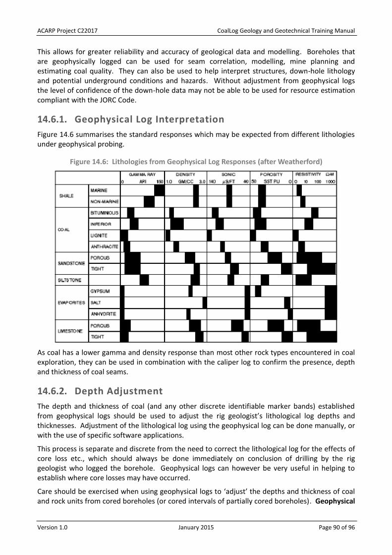
ACARP Project C22017 CoalLog Geology and Geotechnical Training Manual
Version 1.0 January 2015 Page 90 of 96
This allows for greater reliability and accuracy of geological data and modelling. Boreholes that are geophysically logged can be used for seam correlation, modelling, mine planning and estimating coal quality. They can also be used to help interpret structures, down-hole lithology and potential underground conditions and hazards. Without adjustment from geophysical logs the level of confidence of the down-hole data may not be able to be used for resource estimation compliant with the JORC Code.
Geophysical Log Interpretation 14.6.1.
Figure 14.6 summarises the standard responses which may be expected from different lithologies under geophysical probing.
Figure 14.6: Lithologies from Geophysical Log Responses (after Weatherford)
As coal has a lower gamma and density response than most other rock types encountered in coal exploration, they can be used in combination with the caliper log to confirm the presence, depth and thickness of coal seams.
Depth Adjustment 14.6.2.
The depth and thickness of coal (and any other discrete identifiable marker bands) established from geophysical logs should be used to adjust the rig geologist’s lithological log depths and thicknesses. Adjustment of the lithological log using the geophysical log can be done manually, or with the use of specific software applications.
This process is separate and discrete from the need to correct the lithological log for the effects of core loss etc., which should always be done immediately on conclusion of drilling by the rig geologist who logged the borehole. Geophysical logs can however be very useful in helping to establish where core losses may have occurred.
Care should be exercised when using geophysical logs to ‘adjust’ the depths and thickness of coal and rock units from cored boreholes (or cored intervals of partially cored boreholes). Geophysical

ACARP Project C22017 CoalLog Geology and Geotechnical Training Manual
Version 1.0 January 2015 Page 91 of 96
log interpretation is NOT a substitute for observations and measurements of cored intervals made by the rig geologist which will always be more precise and accurate than those determined from interpretation of the geophysical log.
Adjusting coal seam depths and thicknesses is the process of reconciling the geological log with the geophysical log. Coal seams (and other significant lithological units) are ‘picked’ from the validated geophysical log and a comparison made with the lithological log. The lithological log is then adjusted to match the depths interpreted from the geophysical log. It is recommended that the advice of the Exploration Manager is sought regarding the specific method to be used on each project.
Adjustment of non-cored boreholes will require adjustment of each coal seam or interval individually and modification of the adjacent units, whereas a single depth adjustment may be sufficient for a cored or partially cored borehole. Care must be taken when changing the thickness of any logged unit (chip or core) and it must be suitably justifiable.
ACARP Project C22017 CoalLog Geology and Geotechnical Training Manual
Version 1.0 January 2015 Page 92 of 96
BOREHOLE COMPLETION 15.
This section describes the activities that occur once drilling of a borehole has been completed and appropriate down-hole geophysical logs have been obtained. These may not be the responsibilities of the rig geologist but are outlined here as a reference for what needs to be done.
Once the borehole has been completed it is essential to complete a borehole completion record which may be on a form or a peg positioned next to the borehole. This form or peg provides important information about the borehole. Most of this may have already been recorded on the Borehole Status Sheet. The borehole completion record should include:
borehole number and site ID; borehole type (e.g. 4C, HQ, chip, geotech, gas desorption); the total depth of the borehole; the type, size, class and depth of casing; what geophysical tools are required to be run down the borehole; the completion date of the borehole; and the initials of the geologist.
Note: Borehole completion pegs generally do not need to be completed for LOX boreholes.
Following completion of logging the borehole, the borehole may be used for other purposes such as water supply, water monitoring, or installation of infrastructure. This should be made clear on site and in appropriate records so that suitable safety requirements are implemented. If any equipment has been left down the borehole, or there are other activities which may have created a hazard, it must be clearly recorded and communicated to relevant authorities and project managers.
Post drilling completion activities may include cementing of the borehole, a post drilling inspection of the site, a final survey and site rehabilitation. The surveying of each borehole should be completed prior to rehabilitation and removal of casing. All sites should be rehabilitated as soon as practical after drilling unless mining activities are scheduled to progress through the site in the near future (to be defined by onsite management or environmental requirements or conditions). In the case of riverine areas, rehabilitation should be carried out immediately if possible, and certainly before on-set of the wet season.
CEMENTING 15.1.
According to most environmental guidelines, all boreholes will need to be grouted although cement may not be required in areas where mining is scheduled to progress through in a short time after borehole completion. Boreholes that are not cemented have the potential to cause hazards to future mining activities as well as short term impacts on farm cropping and grazing. Most legislation and best practice requires all boreholes to be cemented for the isolation of aquifers and porous formations. There are usually no limitations or exclusions based on depths or thickness of coal seams or for minimum flow rates.
All boreholes must have their total drill depths and diameters recorded, as this information will be used to calculate the volume of cement required to sufficiently cement each borehole.

ACARP Project C22017 CoalLog Geology and Geotechnical Training Manual
Version 1.0 January 2015 Page 93 of 96
POST DRILLING INSPECTION 15.2.
A post drilling inspection should be conducted for each completed borehole, and the following information recorded:
geophysical logs have been obtained; borehole has been temporarily capped; borehole details have been completed and provided to relevant parties; all refuse has been removed; all drilling materials have been removed; oil/chemical spills have been removed; if the sumps need pumping out or de-silting or fencing; and any remedial actions undertaken or required.
FINAL SURVEY 15.3.
On completion of drilling the borehole must be accurately surveyed by a person registered as a qualified surveyor (referred to as a ‘Registered Mine Surveyor’). This is particularly important for determining the borehole collar elevation (or RL), which cannot be determined accurately with a handheld GPS unit.
Depending on the purpose of the borehole, easting and northing coordinates measured by hand held GPS may be sufficient. However, in most circumstances recording the accurate survey location of the borehole is important for compliance with legislation, as well as resource estimates reported according to the JORC Code.
It is important that the surveyor is given clear information on where the boreholes are located, especially when two or more boreholes are drilled on the same drill pad. It is recommended that the surveyor is provided with handheld GPS coordinates for all boreholes that require survey, as well as any additional comments which could help them to locate the site. Clear demarcation identification of the boreholes (which may be as simple as recording the borehole name on the casing or borehole cap) is essential for communicating information to future site visitors, who may be conducting additional activities when the drill crew and rig geologist are not available to escort them.
The surveyor should provide a digital file with easting and northing coordinates and RL in the relevant coordinate system and datum for the project but should always specify the coordinate system and datums used. It is preferable that the coordinates use the MGA94 datum while borehole collar elevation data would typically be as Australian Height Datum (AHD). The surveyor’s name and the date of survey should also be recorded for relevant legislative compliance.
It is critical to specify the elevation at ground level (without the influence of mounded drill cuttings). If it is taken at the top of casing, the casing stick-up must be recorded, so the true ground level can be calculated. The ground level elevation must be recorded in the final survey file.

ACARP Project C22017 CoalLog Geology and Geotechnical Training Manual
Version 1.0 January 2015 Page 94 of 96
BOREHOLE TERMINATION DEPTHS 15.4.
The TD recorded by the rig geologist, the driller, and the geophysical logging engineer may all be different. The TD recorded on the Borehole Status Sheet may be different to the final depth recorded on the Drilling Sheet and to the final lithology depth on the Lithology Sheet if they were recorded at different times or by different people. It is important for the rig geologist to communicate with the driller to ensure consistent depths are recorded on the final records. The RMU & Defect Sheet will not necessarily have a defect record at the borehole TD. Any discrepancies should be resolved before they are entered to the database as most require depths for each of the data types to be exactly the same.
The geophysical tools may give a shallower TD reading due to the position of the receiver or accumulation of drill cuttings or caved material at the bottom of the borehole. If there is a substantial difference (i.e. >5m) it may indicate an error with the driller’s TD.
Any significant discrepancy should be investigated and an appropriate comment recorded. If a geophysical tool has not been able to log a significant interval of the borehole, it may be necessary to clean out or drill the borehole deeper. It may also be necessary to log the borehole through the drill rods to get the logging tool to the TD.
REHABILITATION 15.5.
Rehabilitation requirements for each completed borehole should be recorded on an instruction sheet for the rehabilitation contractor and may include the following:
de-silting of sumps; removal of chips; backfilling and mounding of sumps; casing to be cut-off; whether the borehole requires a plug; whether the tracks require ripping; whether the borehole site requires ripping; whether the borehole site requires seeding with grass; and whether the excavated topsoil requires redistribution.
After rehabilitation works have been completed an inspection should be conducted. A record should be made and photos taken of the rehabilitation undertaken for each completed borehole which provides details of the following:
a record of the borehole cementing; removal of casing; de-silting of sumps; removal of chips; backfilling and mounding of sumps; casing cut-off; borehole has been plugged; ripping has occurred on the borehole site and tracks; reseeding of grass; topsoil has been redistributed;

ACARP Project C22017 CoalLog Geology and Geotechnical Training Manual
Version 1.0 January 2015 Page 95 of 96
site peg has been left at the borehole position; any noxious weeds observed; and all equipment and materials removed.
FINAL CONDITION OF BOREHOLES 15.6.
All boreholes should be rehabilitated according to the relevant code or legislation applying to environmental requirements for the drill site.
Rehabilitation should restore the land to its pre-exploration condition. All rubbish and waste materials should be removed and disposed of appropriately. Any environmental spills must be reported, and any contaminated ground removed.
The rehabilitation of disturbed areas must be carried out as soon as practical after completion of work in the area unless in a riverine area. If the disturbed ground is within a riverine area rehabilitation must be carried out prior to the onset of the wet season.
Most tenements have specific conditions set out in their environmental conditions, which may impact rehabilitation. It is the responsibility of the rig geologist to ensure that these conditions are known and met.
Rehabilitation of exploration activities usually involves three aspects:
Rehabilitation of the boreholes; Rehabilitation of the drill pad; and Rehabilitation of access tracks.
It may be a requirement that boreholes are backfilled as soon as practical following completion of exploration activities, unless they are to be used for further exploration or monitoring purposes. Approval is required by the administering authority to leave boreholes open, and this must be agreed to by the landowner. Many exploration boreholes can be adequately back-filled using the drill cuttings and soil or they may require grouting.
Backfilling and rehabilitation of boreholes must be completed to a standard which ensures that any future exploration or mining development risks are at an acceptable level. This is why boreholes may need to be cemented from their total depth to within 1m of surface. Reasons for this include, but are not limited to, CSG extraction in the area, future underground mining, or the intersection of aquifers in the drilling column.
Rehabilitation of drill pads involves backfilling any earth sumps, spreading stockpiled topsoil back over the disturbed ground, and respreading any cleared vegetation to encourage regrowth. In some cases, re-seeding of tracks or drill pad may be required. Seed should comprise a mixture of native species endemic to the area and care should be taken to establish a similar density of cover to the surrounding undisturbed land.
Access tracks no longer required for exploration should also be rehabilitated and may involve loosening areas of compacted ground, redistributing topsoil and reseeding.

ACARP Project C22017 CoalLog Geology and Geotechnical Training Manual
Version 1.0 January 2015 Page 96 of 96
FINAL DATA CHECK 15.7.
The borehole logging geologist is the frontline person for collecting important and valuable information which cannot be replaced if lost or incomplete other than by incurring the expense of redrilling the borehole. It is critical that the borehole data has been recorded well enough that the next person looking at the information can understand what has happened.
Hence it is very important to ensure the data collected is comprehensive, accurate, valid and complete. This includes ensuring that depth adjustments have been applied to all relevant records, preferably before any lists (e.g. sample details) or reports are generated.
Keeping clear and concise records for the borehole is imperative. These records may be recovered several years later for clarification on a particular area. Therefore the original field data must be complete and must never be destroyed. Every piece of information from the borehole can assist in decisions about mining, and has cost the client a lot of money to collect.
Original borehole field records should be filed and never destroyed, even after the data has been entered into the project database. The files generated and collected are the original evidence about the geology of the area. One of the key requirements for reporting resources and reserves in compliance with the JORC Code is having a transparent dataset. Auditors may use the original hard copy field data to track a borehole from start to finish and to validate the resource geologists’ interpretation.
A checklist of data that should be collected and recorded includes the following:
Site preparation information (maps, photos etc.); Borehole Status Sheet data; Drilling Sheet data; Lithology Sheet data (original and depth adjusted); RMU & Defect Sheet data (if applicable); Point Load Sheet data (if applicable); Water Observation Sheet records; Geophysical logs and metadata; Sample details and chain of custody data; Photographs; Survey data; and Site rehabilitation reports and photos.
It is worthwhile considering the following questions:
Have all of these files been named according to project/client requirements? Have all the files been stored in the appropriate locations, both electronically and as
hard copy? Is the dataset complete? Can these files be easily referenced in several years’ time?

APPENDICES

APPENDICES TABLE OF CONTENTS
A. General Drilling Information
A1. Drilling Equipment
A1.1. Rotary Table Rigs
A1.2. Top Head Drive Rigs
A1.3. Chuck Drive Rigs
A2. Associated Drilling Equipment
A2.1. Drill Rods
A2.2. Drill Bits – Open Borehole/Chip Drilling
A2.2.1. Rock Bits or Rock Rollers Bits (Tri Cone Bits)
A2.2.2. Blade Bits
A2.2.3. Poly Crystalline Diamond Bits (PCD or PDC)
A2.2.4. Hammer Bits
A2.3. Drill Bits Core Drilling
A2.3.1. Diamond Bits
A2.3.2. Poly Crystalline Diamond Coring Bits (PCD/PDC)
A2.3.3. Tungsten Bits
A2.4. Subs
A2.5. Mud/Bean Pumps
A2.6. Air Compressor
A2.7. Casing
A2.7.1. PVC Casing
A2.7.2. Steel Casing
B. Common Drilling Problem
B1. Core Features
B1.1. Spin Marks on Horizontal Partings
B1.2. Reduced Diameter of Core
B1.3. Core Catcher Marks
B2. Core Problems
B2.1. Corrugated Core
B2.2. Wedging Off
B3. Drilling Problems
B3.1. Cavities
B3.2. Broken Ground
B3.3. Lost Circulation in Borehole
B3.4. Collaring in Borehole

B3.5. Bit or Drill String Lost Down Borehole
B3.6. Bogged Rods
B3.7. Hole Caving In
B3.8. Differentially Stuck in Borehole
B3.9. ‘Cooked’ Bit
B3.10. Unusual Drilling Conditions
C. Grainsize Chart
D. V-Notch Weir Chart
E. Visual Percentage Estimation Chart
F. Sandstone Classification Chart
G. Carbonate Classification Chart
H. Coal Brightness
I. Roundness Chart

Page 1 of 12
Appendix A: General Drilling Information

Page 2 of 12
The aim of this section is to give geologists a basic guide regarding drilling rigs on coal exploration and mines sites.
A1. DRILLING EQUIPMENT
There are six main types of drilling rigs: bucket/auger drills, chuck drive, rotary table, top head drive, percussion and sonic drill rigs available to drill boreholes. However, during coal exploration and resource drilling, a rig geologist will most likely supervise drilling activities on rotary table rigs and top head drive rigs. Rig geologists will be occasionally asked to supervise activities on chuck drive rigs. The following sections will give a brief explanation of the uses of these three rig types within the coal sector.
A1.1. ROTARY TABLE RIGS
Rotary Table rigs are often used to undertake open borehole drilling activities and conventional coring on coal exploration sites. These rigs use a Kelly rod that passes through the rotary table which rotates the drill rods during drilling operations (Figure A.1). Table drive rigs range in size being capable of drilling boreholes from 50mm to in excess of 5.5m in diameter with depth capabilities ranging from 50m on the smaller rigs to 1,000m plus on the larger rigs.
Note: Drilling rigs used for petroleum exploration are versions of the rotary table rig and are capable of drilling considerably deeper boreholes. A rotary table is a fast and efficient drilling machine that drills open/chip boreholes using blade bits, rock rollers and hammer bits. These rigs are normally set up to have all associated equipment, such as air compressors, mud pumps and drill rods racks etc. mounted on the rig. This makes them an ideal rig for coal exploration, undertaking open boreholes for water bores (piezometer and hydrological studies), chip boreholes for LOX Programs, pre-collaring core boreholes, chip boreholes to locate coal seams for general resource determination and conventional coring. These rigs are capable and effective at undertaking conventional coring ranging in size from AMLC (26.97mm core) to 8c (202.70mm core). This method of coring requires the core barrel and drill rods to be run in the borehole and once the coring is complete they need to be pulled out of the borehole to recover the core. The main type of bit used for coring is a tungsten bit. However, some rigs are able to run PCD/PDC bits for coring. The main advantage of a rotary table rig is when a borehole has multiple coal seams the seams can be cored and the overburden and interburden can be chipped without major changes of equipment. The down side of the rotary table rig is its slow rotation speeds which do not allow for diamond drilling technics to be effectively used when coring.

Page 3 of 12
Figure A.1: Examples of table drive rigs that may be encountered on a coal exploration or mine sites (on the left is Bourne 1500 and the right is a shaft drill
A1.2. TOP HEAD DRIVE RIGS
Top head drive rigs are hydrostatically driven. The rig has a large hydraulic pump that pumps oil to drive the hydraulic motors that spin the rods or drive winches. The gear boxes on the drill head that drives the tool string is set up with low ratios that deliver a lot of torque and slow rotation speeds suitable for open borehole drilling, or higher ratios that have low torque and fast rotation speeds suitable for diamond coring. This makes the top head drive rig a universal rig that is easily converted from a chipping rig to a diamond coring rig by changing the gear setting in the gear box and the tool string. Top head drives are capable of drilling boreholes from 50mm to approximately 458mm in diameter with depth capabilities ranging from 30m on the small rigs to 3,000m on the larger rigs. These drilling rigs are versatile and efficient machines that can drill open/chip boreholes using blade bits, hammer bits, PCD/PDC bits and rock rollers. When coring a top head can utilise wire line or conventional coring with all types of core bits. The rigs are normally set up to have all minimal associated equipment mounted on the rig. The air compressors, mud pumps and drill rods racks etc. are normally mounted and transported on another truck or trailer. The drill rods are carried on a rod trailer, truck or rod pod to be set up at the back rig during the drilling process (Figure A.2). Thus, the relocation of the rig from site to site takes longer than a table drive rig. However, the versatility of these machines makes them the rig of choice for coal exploration as they are able to conduct all aspects of drilling for coal. Although, the type of borehole being drilled may require the rig and its associated equipment to be set up differently on the drill pad.
Figure A.2: Examples of top head drive rigs that may be encountered on a coal exploration or mine site (left is UDR 1200, right is a Bourne 750)

Page 4 of 12
A1.3. CHUCK DRIVE RIGS
The chuck drive rig is not a common rig on coal exploration sites. It may be mounted on a skid or truck to undertake drilling activities. Because the drill unit is small the machine can be assembled and disassembled on site if required. It can be moved from site to site with a helicopter making it ideal rig for difficult and remote locations. The stroke of the chuck varies in length depending on the size of the rig and may vary in range from 0.50m to 1m. Thus, it is easy to run different length core barrels. These rigs have a high rotation speed as a motor and gear box drives a series of gears to drive the rotation of the chuck combined with two rams (Figure A.3). This makes it a direct mechanical drive from the motor to the drill rods. They are able to deliver high rod rotation speeds to the drill bit which make it ideal for diamond coring. The chuck drive rigs range in size from small units that drill core boreholes 1m deep on construction sites to larger rigs which drill boreholes to depths of 1,000m plus in hard rock. The chuck drives are capable of drilling AQ through to PQ wire line core. These rigs are mainly used for drilling geotechnical angle boreholes because the chuck drive appears to disturb the core less and the borehole does not deviate as much as other types of drilling rigs. The biggest downfall of this rig is while it will gear down for slower rotation speeds to conduct open borehole drilling, it does not handle the locking up of the drill bit that can be associated with open borehole drilling in softer sediments. Thus, the mechanical nature of this rig means that in the hands of an inexperienced driller, major damage may occur to the rig during open borehole drilling.
Figure A.3: An example of Chuck drive rig (Longyear 44)
A2. ASSOCIATED DRILLING EQUIPMENT
A2.1. DRILL RODS
Drill rods are the pipe that connects the drill bit to the driving mechanism of the rig (Figure A.4). These rods come in varying types, diameters and lengths depending on the size of the borehole being drilled. Open borehole rods used in coal exploration are generally 69.85mm (2 ¾”) in

Page 5 of 12
diameter and 6m (20’) in length. However, drill rods may range in diameter up to 120.65mm (4 ¾“) when drilling larger diameter boreholes.
Figure A.4: An example of a typical string of drill rods stored on a pod ready for open/chip borehole drilling
HQ wireline coring rods (88.9mm diameter) are used for coal coring (Figure A.5). NQ coring is done for some geotechnical boreholes due to complications with drilling on HQ.
Figure A.5: Photograph A5: An example of a wire line HQ string of drill rods stored on a pod ready for Core drilling
A2.2. DRILL BITS – OPEN BOREHOLE/CHIP DRILLING
A2.2.1. Rock Bits or Rock Rollers Bits (Tri Cone Bits)
Most rock bits have three cone shaped rollers that have case hardened teeth or tungsten buttons inserted into the rollers (Figure A.6). These bits are designed to use a crushing action to break up the rock. They are used on harder sedimentary strata and handle some softer intrusive or basaltic materials that cannot be cut with a blade bit. However, they are not very successful at drilling

Page 6 of 12
hard rock basalts or intrusive materials. The larger rock bits use a wheel system with tungsten buttons inserted into the wheels to cut the rock. When rock rollers are used it is normal to place heavy drill collars directly behind the bit to ensure there is enough weight on the bit to cut the rock formation. The hardness of the rock dictates the sample size. Moderately hard rock gives a good sample to identify lithology type and hard rock may be ground to a fine powder depending on lithology type. When used in soft or clayey rock types the bit tends to imitate drilling very hard rock or blocks up the bit if insufficient drilling fluid is passing past the cutting edge of the bit.
Figure A.6: Examples of rock roller bits
A2.2.2. Blade Bits
Blade bits are designed to cut the rock like a scraper and cut or break the rock away from the bottom of the borehole in a similar way to a hand drill (Figure A.7). They are very effective in soft to weak rock types. They cut a good size chip for sample identification in soft and weak rock.
Figure A.7: Example of a step blade bit, chevron bit and replaceable blade chevron bit
A2.2.3. Poly Crystalline Diamond Bits (PCD or PDC)
The PCD/PDC bits are ideal for soft to moderately hard rock (Figure A.8). They provide a good sample of the strata they are cutting. They may also handle hard sediments of even hardness. However, they do not handle strata with changing or different hardness at the bit face such as conglomerates or strata with fine hard intrusive veining throughout. These hard and softer sections in the strata have a tendency to break or chip the Poly Crystalline Diamond buttons. They provide a smaller sample than a blade bit but are consistent in size and sufficient to reliably identify the lithology units.

Page 7 of 12
Figure A.8: Shows examples of PCD bits for drilling open/chip boreholes
A2.2.4. Hammer Bits
Hammer bits are designed to drill through hard rock such as basalts, granites, intrusive, conglomerates and hard sandstones (Figure A.9). They are used with high pressure air compressors to operate the piston within the hammer cylinder to strike the bit. They act like a percussion hammer that continually smashes on the rock face to break its way through. The driller will change the rotation speed of the rods depending on how fast the hammer is penetrating the rock strata. It produces a fair size sample chip depending on the hardness of the rock type being drilled. The harder the rock the smaller the sample chip until it is just dust.
Figure A.9: Examples of hammer bits
A2.3. DRILL BITS CORE DRILLING
A2.3.1. Diamond Bits
Diamond bits come in a few variations they may be impregnated, which means the diamonds are mixed in the matrix of the bit surface. The drilling fluid may discharge around the face of the bit (around the face discharge) or discharge through the face of the bit (face discharge) to clear the cuttings from the bit face. Figure A.10 shows the step face bit is a face discharge bit and the impregnated bits are both around the face discharge and face discharge bits. The hardness of the matrix and diamond placement dictates whether the bit is suitable for hard or soft rock drilling. However, when coring soft rock formations diamond bits are not ideal.

Page 8 of 12
Figure A.10: Examples of impregnated and step face diamond bits
A2.3.2. Poly Crystalline Diamond Coring Bits (PCD/PDC)
These bits are ideal for coring soft to moderately hard rock types they cut a nice clean core and due to the chunky nature of the Poly Crystalline Diamond buttons on the face and sides of the bit (Figure A.11). These bits are becoming more popular in coal exploration. However, they do not drill hard sandstones, conglomerates or intrusive bands successfully and are prone to excessive wear and chipping of the Poly Crystalline Diamond buttons in these rock types.
Figure A.11: An example of PCD/PDC coring bits
A2.3.3. Tungsten Bits
These bits are ideal for coring soft to slightly hard rock types they cut a nice even core through soft strata and due to the chunky nature of the tungsten chips on the face and sides of the bit (Figure A.12). These bits are used to core the tertiary sediments in geotechnical boreholes. However, they do not drill fresh siltstones, sandstones, conglomerates or intrusive bands successfully and are prone to excessive wear.
Figure A.12: An example of tungsten core bits

Page 9 of 12
A2.4. SUBS
Subs are the units designed to attach the bits to the drill rods or drill collars and have a threaded jointing point at each end (Figure A.13). There are many different thread types and combinations depending on the tool strings that the drilling company is using. Subs may have a male (Pin) or female (Box) thread end, for example a sub may have a male and female end, both thread ends may be male or female. A cross over sub joins different types of drill rods together such as a hammer rod may be joined to a coring rod.
Figure A.13: Examples of drilling subs
A2.5. MUD/BEAN PUMPS
Mud pumps are designed to deliver large volumes of drilling fluids down the drill string to flush the face of the bit and lift cuttings from the bottom of the borehole to the surface. They are normally a large piston pump which may vary in diameter and stroke length. The larger the pistons and longer the stroke of the piston the more volume of drill fluid can be pumped down a borehole. The size of the mud pump determines how large the borehole diameter can be while drilling open/chip boreholes. It should be noted that while pumps with smaller pistons can be used for large diameter coring, they are not designed to deliver fluids to the bit at pressure and are not ideal for diamond drilling.

Page 10 of 12
Figure A.14: A mud pump
Bean pumps are smaller piston style pump which is designed to pump smaller volumes of drilling fluids at higher pressure than a mud pump. They are an ideal pump for diamond coring, able to handle the higher fluid pressures that are encountered when diamond drilling. It should be noted that the smaller diameter the core borehole the higher the fluid pressures are during drilling. These pumps are not suitable for drilling open/chip boreholes.
Figure A.15: A bean pump
A2.6. AIR COMPRESSOR
Air compressors are used to drill open/chip boreholes during the exploration for coal (Figure A.16). They are more effective at clearing the cuttings from the bit and delivering them to the surface than using drilling fluids. The volume of air is what dictates the size of the borehole and the pressure is what clears the bit face and operates the hammer bit. Air compressors are mainly used in coal exploration to operate hammer bits to chip through hard rock. Most drill bits can be used

Page 11 of 12
with an air compressor, some bits require water injection during drilling to keep the bit lubricated and cool. The size air compressor used with most rigs is 350 PSI and 900 CFM. However, drillers that are drilling larger diameter or deeper boreholes tend to use compressors rated at 900 PSI and 1,200 to 1,500 CFM. The air compressors are connected to the rig with a 2” high pressure air hose (bull hose).
Note: Do not conduct geological activities in close proximity of the bull hose as they are prone to rupturing and can cause severe injury.
Figure A.16: An example of an air compressor set up at the rig drilling an open/chip borehole
A2.7. CASING
There are two main reasons for using casing in a borehole; to support the unconsolidated or weathered rock strata while you drill the consolidated fresh rock to locate the coal seams or to support the drill rods if you are drilling through a larger diameter borehole. Steel and PVC casing are the two types of casing used during drilling for coal. The choice of which type of casing to use normally relates to the cost and purpose it is intended to be used for. However, the strength of the casing may be an issue during drilling as the properties of the lithology being drilled (ground conditions) may be detrimental to the casing type being used. For example, certain clays within the tertiary sediments have swelling properties which have been known to crush PVC casing. Once the casing is run into the borehole there is normally 200mm to 300mm remaining above ground level (stick up). The casing is centred and sealed into the borehole with A&B foam, rapid set cement or a similar product. This will stop the drill fluids and cutting (rock chips) coming up the outside of the casing.

Page 12 of 12
Note: Some boreholes will require two or three strings of casing to be run to ensure that the geologist gains the best information possible from the borehole. For example, a borehole may have 6 to 12m of conductor casing at the borehole surface, a second string to hold back a sand or loose gravel section within the tertiary sediments and then a third string will be run down to the fresh or harder sediments within the coal measures.
A2.7.1. PVC Casing
PVC casing has become the most popular type of casing on coal exploration sites because it can be left in the ground after the borehole is drilled and will not have an impact during the mining process. It is normally available in diameters from 0.50”/12.7mm to 32.0”/800mm. The main classes of PVC used are class 6, 9, 12 and 18, with 6 being the weakest and 18 the strongest. On most coal projects the sizes of casing used is determined by the project manager/geologist. However, on some projects the choice of casing sizes will be made by the drilling company and/or the driller. Generally, 5” to 5 ¾ ” is the most popular casing size for chip/open boreholes with 3 to 6 metres of 7” or 8” steel conductor casing used at the surface of the borehole. During the drilling of LOX boreholes 6 to 18 metres of 4” or 5” surface casing is used depending on the depth of tertiary sediments. When coring 4” to 5” casing is normally used for HQ core boreholes, 7” casing is generally for 4” coring and 10” casing for 6” coring.
Note: Old PVC casing is prone to shattering when being run into the borehole and the pieces can become dangerous projectiles. Thus, Geologists and non-essential personnel must be in a safe location while casing is being run into the borehole.
A2.7.2. Steel Casing
Steel casing is not popular on coal exploration sites because it impacts on the mining processes if it remains in the ground of a potential mine site. Thus, when steel casing is run into a borehole it must be removed at the completion of the borehole. If it cannot be removed from the borehole it must be reported to project management before moving to the next drill site.
Note: On some projects the use of steel casing requires approval from the SSE even though it is strong and effective method of supporting the unconsolidated rock strata. Steel casing is used when drilling 8” (large diameter) core boreholes or when using HWT (4”) steel casing to support the HQ drill rods in a pre-collared borehole with a casing diameter larger the 5”. This casing may be threaded or flush joint which requires welding to join the lengths together. Steel casing may be used when the ground conditions require a stronger casing than class 18 PVC. The project management may approve the use of steel casing for geotechnical angle boreholes, gas production wells or in areas where the ground conditions require the casing be reamed through the tertiary sediments. It is important that geologist forward plan and communicate with project management regarding casing and drilling issues to confirm the correct casing is used to ensure the drilling program runs smoothly.
Note: If a casing is to be welded the geologist should confirm that a hot works permit has been attained by the drillers to avoid unnecessary delays and stand-by time.

Page 1 of 6
Appendix B: Common Drilling Problem

Page 2 of 6
If the geologist communicates with the driller and carefully observes the drill cores, they will gain useful information that will assist them in interpreting drilling conditions and more accurately allocate core losses. Some commonly observed features of drill cores and drilling problems are set out below.
B1. CORE FEATURES
B1.1. SPIN MARKS ON HORIZONTAL PARTINGS
These are seen on bedding planes or a horizontal break in the core and are revealed as concentric rings or smooth concentric ridges on the surface where the core has broken. These marks are caused when the core starts spinning inside the inner tube and grinds the two surfaces together as the core is pushed in the tube as the bit cuts the new strata. Presence of spin marks indicates there has been grinding of the core on these surfaces and small core losses may be allocated to this interval.
B1.2. REDUCED DIAMETER OF CORE
A reduced diameter of the core normally indicates that a section of core that was not recovered in the previous run has been over drilled (redrilled) to commence the next core run. You may be able to see or feel a ‘lip’ on the core surface where the core returns to its normal diameter at the base of the over drilled section. This process will break the core left in the borehole and recut it into odd shaped pieces of core. It may also occur within a run where the driller has encountered difficulties and has pulled back on the drill and over drilled the core before continuing drilling. Sometimes you may observe oblique spin markings on the exterior surface of such sections of core. Core loss may be allocated to the top of such intervals. If the drill bit is new the reduced diameter core maybe a result of an incorrect gauge of the drill bit cutting slightly undersize core. In soft strata a reduced diameter of the core may be also be caused when an excessive volume of drill fluid being pumped between the core and the bit, especially when an around-the-face discharge bit is being used.
B1.3. CORE CATCHER MARKS
Sometimes the core catcher does not grip the core sufficiently and the core slips down through the catcher, leaving thin vertical gouge lines around the circumference of the core. The marks may also occur when the barrel is lowered over core lost in the previous run. Thus, if such markings are observed on the top of the core run, this indicates that this section of core was drilled in the previous run.

Page 3 of 6
B2. CORE PROBLEMS
B2.1. CORRUGATED CORE
When core has a corrugated surface it is usually indicative of too much weight on the bit, either as a result of the driller using too much pull down to increase bit penetration (usually in an effort to drill too fast), or because the driller is not holding back enough rod weight with the rig thereby allowing the excess weight of the drill string to bear down on the bit.
B2.2. WEDGING OFF
When drilling core boreholes the driller will often encounter strata which are sheared or jointed at high angles. In these circumstances the driller will sometimes report that the core has ‘wedged off’ with in the inner tube. This is usually the result of the core slipping on a high angle joint within the inner tube and jamming the core in the inner tube during the coring process resulting in the driller coring a short run. If the driller continues to attempt to force the drilling process and force more core into the inner tube it will start to break up the core and grind the core away resulting in core loss. Wedging off can also occur in conglomerate when the bit cuts hard clasts or pebbles and they vibrate loose and grip (wedge off) the inside of the inner tube causing the core to jam in the tube.
B3. DRILLING PROBLEMS
B3.1. CAVITIES
Naturally occurring cavities can be present in coal measures. The presence of a cavity may be indicated by loss of circulation or an increased penetration rate as the drill string accelerates down the borehole through the cavity interval. The driller will normally let you know that a cavity has been encountered. The presence and location of the cavity should be logged under the appropriate code, as accurately as possible. There is no core loss in this circumstance.
B3.2. BROKEN GROUND
When the core is significantly broken, it maybe a result of the rock strata being a shear or fault zone. As general observation, it may be said that core from shear zones will consist of large pieces of fragmented rock (possibly slickensided) with uniformly finely ground rock material present between the fragments. This can be contrasted with core which has been fractured as a result of the drilling process (and which the driller may endeavour to pass off as a shear zone). These latter zones may also have finely ground material in between the rock fragments, but in these cases close inspection of the fine material (e.g. by probing with a pocket knife). While this topic does engage differences of opinion between the driller and the geologist over the reason for the core breakage. Regardless of whether the rock is broken because of the drilling process or broken rock strata, if core loss has occurred in the run, the loss should be allocated to the broken zone.

Page 4 of 6
Note: Core recovery is paramount in the coal seams and most drilling contractors are required to achieve a 95% recovery of the coal seam as a clause in their contract or the seam is redrilled regardless of the perceived cause of the broken core.
B3.3. LOST CIRCULATION IN BOREHOLE
This is when the drilling fluid or air does not return to the top of the borehole indicating that it is being pumped into the rock strata. This implies that there is a highly broken or porous zone has been encountered in the borehole. If it is a chip borehole then it is a major problem for the driller if circulation is not restored his drill string may get stuck in the borehole by the drill cuttings. From a geological prospective, if there is no circulation in the borehole, it means that there are no samples of the rock strata being drilled coming to the surface. Drillers can use a range of products such as hy-seal, bran, silica gel or they may even pump cement into the borehole in attempts to seal any broken or porous zones. If the borehole cannot be sealed for drilling to recommence the borehole may have to be abandoned. While it is not ideal to core when there is no circulation in the borehole, it is possible. As there is only a small volume of drill fluid being circulated through the borehole when coring and the cuttings are very fine, it is possible to continue coring with no circulation in the borehole and it is called drilling blind. The driller becomes more aware of the forces on rods and regularly monitors the rotation pressure gauges to ensure the rods are spinning freely in the borehole. Once the fine cuttings gradually seal the porous section of the borehole up circulation will return.
B3.4. COLLARING IN BOREHOLE
‘Collaring’ occurs when the drill cuttings gather in sections of the borehole and gradually build up, thereby reducing the diameter of the borehole. While the rods may be free in the borehole when the driller trips his rods out of the borehole, the bit will become stuck in a collared section of the borehole. This is not normally a major problem as the driller will back ream his bit out of the borehole. However, he will have to ensure all the collars from the surface to the bottom are reamed out of the borehole and recondition the borehole with clean drill mud to ensure it is safe to continue drilling deeper. This may take a few hours depending on the borehole depth to ensure he has reamed all the collars removed from the borehole. Collars in the borehole can also cause problems for the geophysical logger and cause his probe to become stuck in the borehole when he is logging. Thus, it important the driller flushes and conditions the borehole before tripping out at the end of the borehole.
B3.5. BIT OR DRILL STRING LOST DOWN BOREHOLE
On occasion the bit or a drill rod will break off down the borehole during the drilling process and must be retrieved from the bottom of the borehole. This procedure is known as ‘fishing’. The driller will attempt to retrieve the rods/bit with a carrot tap that screws into the inside of the rod/bit or bell tap that screws on the outside of the rod/bit lost down the borehole. If the bit or rod has unthreaded its self then the driller will attempt to reconnect the threads back together. If the bit cannot be re-screwed back on by manipulation of the rods or taps, there are many other various devices such as baskets, large magnets or rod recovery lifters (e.g. a ‘fishing tools’) are available to retrieve the bit or drill rods. If it is just the bit that is lost in the borehole and the above listed devices are unsuccessful, it is possible, as a last resort, a suitable sized core barrel

Page 5 of 6
may be used to core over the top of the detached bit so that drilling can proceed. However, it may be necessary to abandon the borehole and redrill it.
B3.6. BOGGED RODS
This occurs when the driller is rushing and is forcing the drill bit in to the ground without sufficient drilling fluid or air circulating past the face of the bit. This lack of drilling fluid or air does not clear the cuttings from the face and sides of the drill bit and bogs the bit into the bottom of the borehole. Once the bit becomes stuck in the bottom of the borehole it can be very difficult to remove depending on how deep the driller has drilled with the poor circulation. This may also occur if the driller does not flush the borehole at the end of each rod to ensure that all the cuttings are out of the borehole. The accumulation of cuttings in the borehole will settle to the bottom of the borehole when the drill fluid or air is shut off to change a rod. It is when the rod is changed that the cuttings settle behind the bit and blocks of the annulus of the borehole. If there are sufficient cuttings in the borehole, the driller will not be able to regain circulation of the drill fluid or air or move his rods within the borehole and thus become bogged in the borehole. This may result in a lot of time fishing the rods out of the borehole to recommence drilling.
B3.7. HOLE CAVING IN
When drilling unstable strata such as sands, gravels, fault zones and shear zones, the borehole will have a tendency to cave in during the drilling process unless these sections are cased off. If the borehole caves in it buries the bit and rods in the borehole. Most drillers use a variety of techniques to free the rods but this is not always successful in which case rods and drill bit are lost. Thus, if a driller expresses concern that there may be a risk of the borehole caving in and getting his rods stuck in the borehole, you should immediately put the rig on stand-by and contact the Project Manager for directions. This is essential to avoid disputes over liability for time spent attempting to free the rods, and in the worst case scenario, the cost of gear lost down the borehole.
B3.8. DIFFERENTIALLY STUCK IN BOREHOLE
This occurs in deeper boreholes drilled with mud and is caused when the pressure in the borehole is greater than formation pressure, as is usually the case. The simple explanation of differentially stuck is when the drill rods are pressed against the side of the borehole by the forces in the borehole, which the hold the rods in the mud cake on the wall of the borehole and the rod becomes stuck. To break the hold on the rods can require hundreds of tonnes of downward force to break the rods free of connection to the wall of the borehole, and on many occasions may prove impossible. Changing the viscosity and weight of the drilling fluid or flushing the borehole with water in many cases will relieve the pressure difference and releasing the stuck drill string. It would be beneficial to speak with a mud doctor to choose one of the many products that can be used to strip the mud cake from the borehole and release the stuck drills string. However, this may cause other issues such as the borehole caving in and once the drill string is freed the borehole needs to be reconditioned as soon as possible.

Page 6 of 6
B3.9. ‘COOKED’ BIT
When a driller cooks the drill bit it means that he has over heated the bit and changed the cutting ability of the bit. This overheating makes the bit non-functional as it changes the hardness of the bit and allows the cutting surfaces to polish or wear excessively and not cut the rock. The usual cause is insufficient volume drilling fluids to cool the bit. A cooked bit may also be caused by the drilling methods techniques used by the driller (e.g. the incorrect rotation speed combined with fast or slow penetration rates drilling hard rock).
B3.10. UNUSUAL DRILLING CONDITIONS
A record of poor or unusual drilling conditions should be entered on the logging sheets. This includes caving, lost circulation, lost returns/core, drilling equipment problems, sudden increase in gas intrusions, unstable ground, problems running casing in the borehole, if the drill loading up excessively while drilling, or a combination of these things. Weak walls in the borehole often collapse onto the rod string and this will produce a cavity. The cavity sometimes causes loss of circulation and may also prevent movement of the drill string.
The geologist should note any swelling clays in the borehole that will break the PVC casing or any geological structures that will impact on future drilling. Other geological boundaries such as tertiary, standing water levels, coal measure boundaries or any structure which can be indicators of faulting or other important geotechnical features should be recorded in the comments section if there is no field to record the information.

Page 1 of 2
Appendix C: Grainsize Chart

Page 2 of 2
PARTICLE SIZE TERMINOLOGY

Page 1 of 2
Appendix D: V-Notch Weir Chart

Page 2 of 2
RECTANGULAR AND V-NOTCH WEIR BOARD DISCHARGE TABLE

Page 1 of 2
Appendix E: Visual Percentage Estimation Chart

Page 2 of 2
DIAGRAMS REPRESENTING VARIOUS PERCENTAGES OF GRAINS

Page 1 of 2
Appendix F: Sandstone Classification Chart

Page 2 of 2
SANDSTONE CLASSIFICATION CHART

Page 1 of 2
Appendix G: Carbonate Classification Chart

Page 2 of 2
CLASSIFICATION OF CARBONATE SEDIMENTS

Page 1 of 2
Appendix H: Coal Brightness

Page 2 of 2
COAL BRIGHTNESS

Page 1 of 2
Appendix I: Roundness Chart

Page 2 of 2
ROUNDNESS AND SPHERICITY